Embed Size (px)
Citation preview
PILOT'S OPERATING HANDBOOKAND FAA APPROVED
AIRPLANE FLIGHT MANUAL
for the
diffi c24RFAA APPROVED IN NORMAL CATEGORY BASEDON CAR 3. THIS DOCUMENT MUST BE CARRIEDIN THE AIRPLANE AT ALL TIMES AND BE KEPTWITHIN REACH OF THE PILOT DURING ALLFLIGHT OPERATIONS.
Mfrs Serial No.
FR
po
eNd
W. H SCHULTZBEECH AIRCRAFT CORPORATIONDOA CE-2
THIS HANDBOOK SUPERSEDES PILOT S OPERATING MANUAL P/N 169-590025-1 AND FAA APPROVED AIRPLANE FLIGHT MANUAL MCOC32644-7.
PIN 169-590025-158 169-590025-1582Reissued: November, 1980 Revised: June, 1984
MC-478
N24017
PUBLISitED BYCOMMERCIAL PUBLICATIONS
BEECH AIRCRAFT CORPORATlONWICIHTA. KANSAS ß720I
IL S A
Morreer of GAMAGeneral Aviaton
A Raytheon Company Manufacturers Assodanon
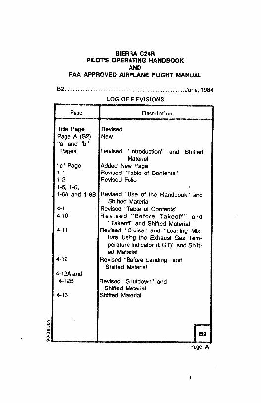
SIERRA C24RPILOT'S OPERATING HANDBOOK
ANDFAA APPROVED AIRPLANE FLIGHT MANUAL
B2 ......................... . ... ........................... June, 1984
LOG OF REVISIONS
Page Description
Title Page RevisedPage A (82) New"a" and "b"
Pages Revised "Introduction" and ShiftedMaterial
"c" Page Added New Page1-1 Revised "Table of Contents"1-2 Revised Folio1-5, 1-6,1-6A and 1-68 Revised "Use of the Handbook" and
Shifted Material4-1 Revised "Table of Contents"4-10 Revised "Before Takeoff" and
"Takeoff" and Shifted Material4-11 Revised "Cruise" and "Leaning Mix-
ture Using the Exhaust Gas Tem-perature Indicator (EGT)" and Shift-ed Material
4-12 Revised "Before Landing" andShifted Material
4-12A and4-128 Revised "Shutdown" and
Shifted Material4-13 Shifted Material
Page A

SIERRA C24RPILOT'S OPERATING HANDBOOK
ANDFAA APPROVED AIRPLANE FLIGHT MANUAL
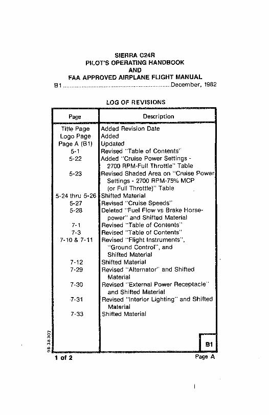
B1 ....................... .........................Decernber, 1982
LOG OF REVISIONS
Page Description
Title Page Added Revision DateLogo Page Added
Page A (B1) Updated5-1 Revised "Table of Contents"
5-22 Added "Cruise Power Settings -
2700 RPM-Full Throttle" Table5-23 Revised Shaded Area on "Cruise Power
Settings - 2700 RPM-75% MCP(or Full Throttle)" Table
5-24 thru 5-26 Shifted Material5-27 Revised "Cruise Speeds"5-28 Deleted "Fuel Flow vs Brake Horse-
power" and Shifted Material7-1 Revised "Table of Contents"7-3 Revised "Table of Contents"
7-10 & 7-11 Revised "Flight Instruments","Ground Control", andShifted Material
7-12 Shifted Material7-29 Revised "Alternator" and Shifted
Material7-30 Revised "External Power Receptacle"
and Shifted Material7-31 Revised "Interior Lighting" and Shifted
Material7-33 Shifted Material
1 of 2 Page A
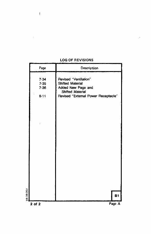
LOG OF REVISIONS
Page Description
7-34 Revised "Ventilation"7-35 Shifted Material7-36 Added New Page and
Shifted Material8-11 Revised "External Power Receptacle"
2 of 2 Page A
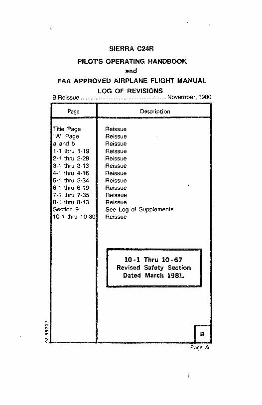
SIERRA C24R
PILOT'S OPERATING HANDBOOKand
FAA APPROVED AIRPLANE FLIGHT MANUALLOG OF REVISIONS
B Reissue ......... ................ ................:....... November, 198f
Page Description
Title Page Reissue"A" Page Reissuea and b Reissue1-1 thru 1-19 Reissue2-1 thru 2-29 Reissue3-1 thru 3-13 Reissue4-1 thru 4-16 Reissue5-1 thru 5-34 Reissue6-1 thru 6-19 Reissue7-1 thru 7-35 Reissue8-1 thru 8-43 ReissueSection 9 See Log of Supplements10-1 thru 10-30 Reissue
O-1 Thru 10-67Revised Safety Section
Dated March 1981.
Page A

BEECHCRAFTSierra C24R
INTRODUCTION
The format and contents of this Pilot's Operating Handbookand FAA Approved Airplane Flight Manual conform toGAMA (General Aviation Manufacturers Association)Handbook Specification Number 1. Use of this specificationby all manufacturers will provide the pilot with the same typeof data in the same place in all handbooks.
In recent years, BEECHCRAFT handbooks contained mostof the data now provided. However, the new handbookscontain more detailed data and some entirely new data.
For example, attention is called to Section X (SAFETYINFORMATION). BEECHCRAFT feels that it,is highlyimportant to have Safety loformation in a condensed form inthe hands of the pilots. The Safety Information should beread and studied. Periodic review will serve as a reminder ofgood piloting techniques.
WARNING
Use only genuine BEECHCRAFT or BEECHCRAFTapproved parts obtained from BEECHCRAFT approvedsources, in connection with the maintenance and repair ofBeech airplanes.
Genuine BEECHCRAFT parts are produced and inspectedunder rigorous procedures to insure airworthiness andsuitability for use in Beech airplane applications. Partspurchased from sources other than BEECHCRAFT, eventhough outwardly identical in appearance, may not have hadthe required tests and inspections performed, may bedifferent in fabrication techniques and materials, and maybe dangerous when installed in an airplane.
June,1984 a
BEECHCRAFTSierra C24R
Salvaged airplane parts, reworked parts obtained from non-
BEECHCRAFT approved sources, or parts, components, orstructural assemblies, the service history of which isunknown or cannot be authenticated, may have beensubjected to unacceptable stresses or temperatures or haveother hidden damage, not discernible through routine visualor usual nondestructive testing techniques. This may renderthe part, component or structural assembly, even thoughoriginally manufactured by BEECHCRAFT, unsuitable andunsafe for airplane use.
BEECHCRAFT expressly disclaims any responsibility formalfunctions, failures, damage or injury caused by use ofnon-BEECHCRAFT approved parts.
b June,1984
SIERRA C24R
PILOT'S OPERATING HANDBOOK
AND
FAA APPROVED AIRPLANE FLIGHT MANUAL
TABLE OF CONTENTS
SECTION l...................... . ........................ GENERAL
SECTION II....................... ...................... LIMITATIONS
SECTION III.......................... EMERGENCY PROCEDURES
SECTION IV .................................NORMAL PROCEDURES
SECTION V ........................ ......................PERFORMANCE
SECTION VI ... WEIGHT AND BALANCE/EQUIPMENT LIST
SECTION VII ............................... SYSTEMS DESCRIPTION
SECTION VIII ................................ HANDLING,SERVICINGAND MAINTENANCE
SECTION IX ....................... ........................SUPPLEMENTS
SECTION X ....................................SAFETY INFORMATION
June, 1984 e

BEECHCRAFTSierra C24R
SECTION I
GENERALTABLE OF CONTENTS
SUBJECT PAGE
Introduction.......................... ...........................1-3
Important Notice ........................ . .........................1-3
Use ofthe Handbook ........................... .........................
1-4
Revising the Handbook......................... ........................
1-6Supplements Revision Record........................................1-6AVendor-Issued STC Supplements ..................................
1-6AAirplane Three View............................. ...........................
1-7Ground Turning Clearance ...............................................
1-8Descriptive Data .......................... . ........................
1-9Engine......................... ........................
1-9Propeller........................... . .. ......................
1-9Fuel......................... . .......................
1-9Fuel Tanks ............................ ..........................
1-10Oil....................... . ........................
1-10OilCapacity ........................... ........................
1-10Approved Oil Types ....................... . . .....................
1-10
Maximum Certificated Weights .......................................
1-10Cabin and Entry Dimensions........................................... 1-11Baggage Space and Entry Dimensions........................... 1-11Specific Loadings............................................................ 1-11Symbols, Abbreviations and Terminology....................... 1-12
General Airspeed ........................................................
1-12Meteorological........................ . .........................
1-14Power......................................... .......................
1-15Engine Controls and Instruments................................ 1-15Airplane Performance and Flight Planning ..................
1-16Weight and Balance ........................ . .......................
1-17
June, 1984 1-1

Section i BEECHCRAFTGeneral Sierra C24R
INTENTIONALLY LEFT BLANK
1-2 June, 1984
BEECHCRAFT Section iSierra C24R General
THANK YOU . . . for displaying confidence in us byselecting a BEECHCRAFT airplane. Our design engineers,assemblers and inspectors have utilized their skills andyears of experience to ensure that the BEECHCRAFTmeets the high standards of quality and performance forwhich BEECHCRAFT airplanes have become famousthroughout the world.
IMPORTANT NOTICE
This handbook must be read carefully by the owner andoperator in order to become familiar with the operation ofthe airplane. Suggestions and recommendations have beenmade within it to aid in obtaining maximum performancewithout sacrificing economy. Be familiar with, and operatethe airplane in accordance with the Pilot's OperatingHandbook and FAA Approved Airplane Flight Manual,and/or placards which are located in the airplane.
As a further reminder, the owner and operator of thisairplane should also be familiar with the Federal AviationRegulations applicable to the operation and maintenance ofthe airplane and FAR Part 91 General Operating and FlightRules. Further, the airplane must be operated andmaintained in accordance with FAA Ainworthiness Directiveswhich may be issued against it.
The Federal Aviation Regulations place the responsibility forthe maintenance of this airplane on the owner and theoperator who should ensure that all maintenance is done byqualified mechanics in conformity with all airworthinessrequirements established for this airplane.
All limits, procedures, safety practices, time limits, servicing,and maintenance requirements contained in this handbookare considered mandatory for continued airworthiness tomaintain the airplane in a condition equal to that of itsoriginal manufacture.
November, 1980 . 1-3
Section i BEECHCRAFTGeneral Sierra C24R
Authorized BEECHCRAFT Aero or Aviation Centers orInternational Distributors or Dealers can providerecommended modification, service, and operatingprocedures issued by both the FAA and Beech AircraftCorporation, which are designed to get maximum utility andsafety from the airplane.
USE OF THE HANDBOOK
The Pilot's Operating Handbook is designed to maintaindocuments necessary for the safe and efficientoperation ofthe airplane. The handbook has been prepared in loose leafform for ease in maintenance and in a convenient size forstorage. The handbook has been arranged with quickreference tabs imprinted with the title of each section andcontains ten basic divisions:
Section i GeneralSection 11 LimitationsSection Ill Emergency ProceduresSection IV Normal ProceduresSection V PerformanceSection VI Weight and Balance/Equipment ListSection Vil Systems DescriptionSection VIII Handling, Servicing and MaintenanceSection IX SupplementsSection X Safety Information
NOTESExcept as noted, all airspeeds quoted in thishandbook are indicated airspeeds (IAS) andassume zero instrument error.
Due to the large variety of airplaneconfigurations available through optionalequipment, it should be noted that in describingand illustrating the handbook, optionalequipment may not be designated as such in
1-4 November, 1980
BEECHCRAFT Section iSierra C24R General
every case. Through variations provided bycustom designing, the illustrations in thishandbook will not be typical of every airplane.
The ownerloperator should always refer to allsupplements, whether STC Supplements orBeech Supplements, for possible placards,limitations, normal, emergency and otheroperational procedures for proper operation ofthe airplane with optionalequipment installed.
NOTICE
The following information may be provided tothe holder of this manual automatically:
L Original issues and revisions ofBEECHCRAFT Service Bulletins
2. Original issues and revisions of FAAApproved Airplane Flight ManualSupplements
3. Reissues and Revisions of FAA ApprovedAirplane Flight Manuals, Flight Handbooks,Owner's Manuals, Pilot's Operating Manuals,and Pilot's Operating Handbooks
This service is free and will be provided only toholders of this handbook who are listed on theFAA Aircraft Registration Branch List or theBEECHCRAFT International Owner'sNotification Service List, and then only ifyou arelisted by airplane serial number for the modelfor which this handbook is applicable. Fordetailed information on how to obtain "Revision
June, 1984 1-5
Section i BEECHCRAFTGeneral Sierra C24R
I Service" applicable to this handbook or otherBEECHCRAFT Service Publications, consult aBEECHCRAFT Aero or Aviation Center orInternational Distributor or Dealer, or refer to thelatest revision of BEECHCRAFT ServiceBulletin No. 2001.
NOTICE
Beech Aircraft Corporation expressly reservesthe right to supersede, cancel, and/or declareobsolete, without prior notice, any part, partnumber, kit, or publication referenced in thismanual.
REVISING THE HANDBOOK
immediately following the "Title Page" is the "Log ofRevisions" page(s). The Log of Revisions pages are usedfor maintaining a listing of all effective pages in thehandbook (except the SUPPLEMENTS section), and as arecord of revisions to these pages. In the lower right cornerof the outlined portion of the Log of Revisions is a boxcontaininga capital letter which denotes the issue or reissueof the handbook. This letter may be suffixed by a numberwhich indicates the numerical revision. When a revision toany information in the handbook is made, a new Log ofRevisions will be issued. AII Logs of Revisions must beretained in the handbook to provide a current record ofmaterial status until a reissue is made.
WARNING
When this handbook is used for airplaneoperational purposes it is the pilot'sresponsibility to maintain it in current status.
1-6 June, 1984
BEECHCRAFT Section iSierra C24R General
SUPPLEMENTS REVISION RECORD
Section IX contains supplements and a Log of Supplementspage. On the "Log" page is a listing of supplementalequipment available for installation on the BEECHCRAFTairplane.
Upon receipt of a new or revised supplement, compare the"Log" page just received with the existing "Log" page in themanual. Retain the "Log" page with the latest date on thebottom of the page (this log will usually have the greaternumber of entries) and discard the other log.
VENDOR-ISSUED STC SUPPLEMENTS
When a new airplane is delivered from the factory, thehandbook will contain either an STC (Supplemental TypeCertificate) Supplement or a Beech Flight ManualSupplement for all items requiring a supplement. If a newhandbook is purchased at a later date for operation of theairplane, it is the responsibility of the ownerloperator to seethat all required STC Supplements (as well as weight andbalance and other pertinent data) are retained for use in thenew handbook.
June, 1984 1-6A
Section i BEECHCRAFTGeneral Sierra C24R
INTENTIONALLY LEFT BLANK
1-68 June, 1984
BEECHCRAFT Section iSierra C24R General
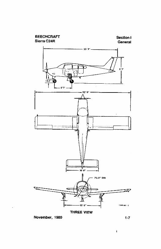
25' 9"
8'1"
6' I"
10' 8"
76.0" DIA
THREE VIEWNovember, 1980 1-7
Section i BEECHCRAFTGeneral Sierra C24R
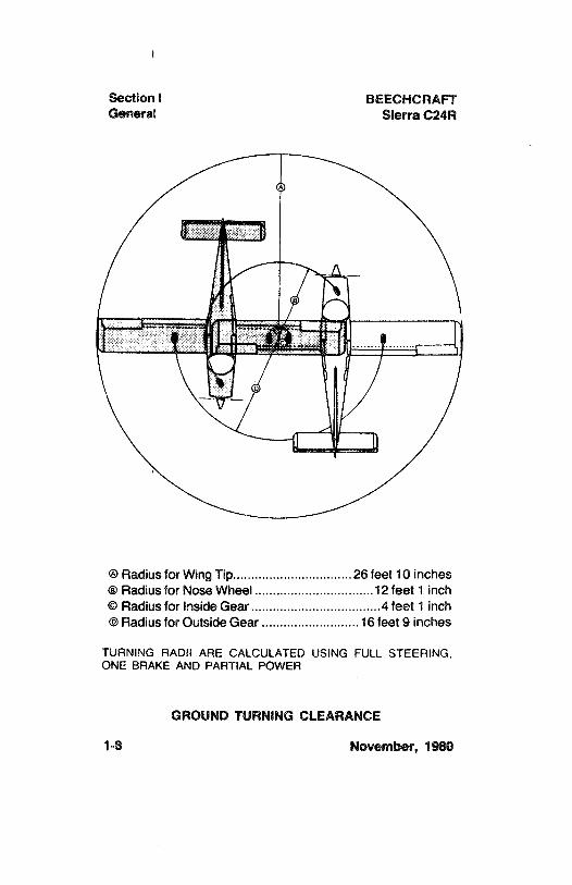
Radius for Wing Tip.................................26 feet 10 inchesRadius for Nose Wheel .................................12 feet 1 inch
© Radius for Inside Gear ....................................4 feet 1 inch@Radius for Outside Gear ...........................16 feet 9 inches
TURNING RADil ARE CALCULATED USING FULL STEERING.ONE BRAKE AND PARTIAL POWER
GROUND TURNING CLEARANCE
1-8 November, 1980
BEECHCRAFT Section iSierra C24R General
DESCRIPTIVE DATA
NOTE
MC-449, MC-452 thru MC-673 are 14-voltsystems. The battery switch is placardedBATTERY & ALT and the alternator switch isplacarded ALT (or ALT FIELD). 28-volt systemsMC-674 and after, are placarded BATTERY forthe battery switch and ALT FIELD for thealternator switch. AII items throughout thishandbook that refer to battery switch refer toeither BATTERY & ALT switch or BATTERYswitch depending upon configuration.
ENGINE
One Avco Lycoming engine model 10-360-A1B6. It is a fuel-injected, direct-drive, air-cooled, horizontally opposed, 4-cylinder, 200-horsepower-rated engine.
Take-off and Maximum ContinuousPower......................................... Full Throttle at 2700 RPM
PROPELLER
Hartzell constant-speed, two-blade, aluminum-alloypropeller using HC-M2YA-18F hub with F7666A blades andan A2298-2P spinner. Diameter is 76 inches, no cutoffpermitted.
FUEL
Aviation Gasoline Grade 100 (green), or 100LL (blue)minimum.
November, 1980 1-9
Section i BEECHCRAFTGeneral Sierra C24R
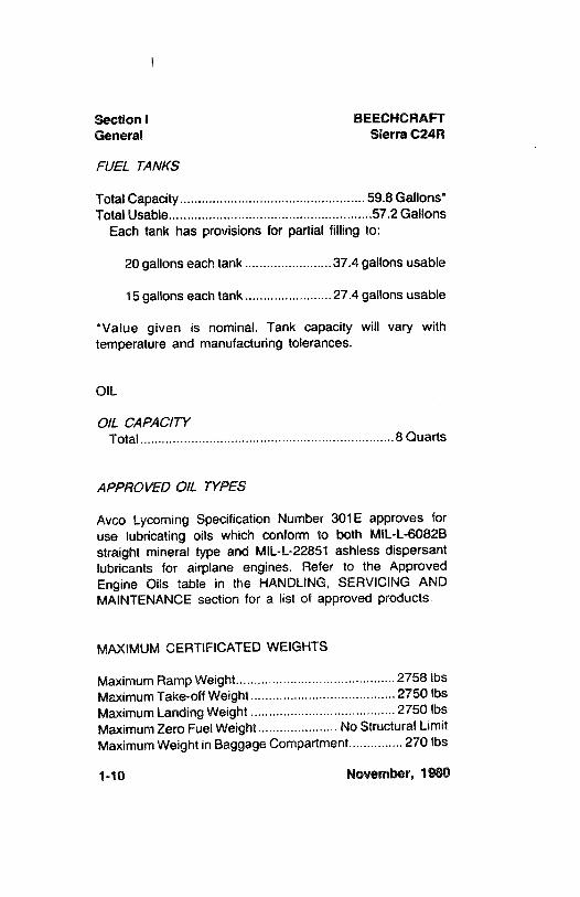
FUEL TANKS
Total Capacity......................... ......................... 59.8 Gallons*Total Usable.......................... .............................57.2 Gallons
Each tank has provisions for partial filling to:
20 gallons each tank ........................37.4 gallons usable
15 gallons each tank ........................27.4 gallons usable
*Value given is nominal. Tank capacity will vary withtemperature and manufacturing tolerances.
OIL
O/L CAPACITYTotal....................... ......................8Quarts
APPROVED O/L TYPES
Avco Lycoming Specification Number 301E approves foruse lubricating oils which conform to both MIL-L-6082Bstraight mineral type and MIL-L-22851 ashless dispersantlubricants for airplane engines. Refer to the ApprovedEngine Oils table in the HANDLING, SERVICING ANDMAINTENANCE section for a list of approved products.
MAXIMUMCERTIFICATED WEIGHTS
Maximum Ramp Weight...................... ...................2758 ibsMaximum Take-off Weight ........................................ 2750 lbsMaximum Landing Weight ........................................2750 lbsMaximum Zero Fuel Weight...................... No Structural LimitMaximum Weight in Baggage Compartment............... 270 lbs
1-10 November, 1980
BEECHCRAFT Section iSierra C24R General
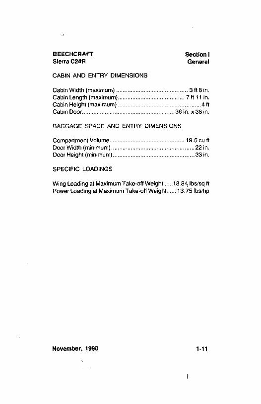
CABIN AND ENTRY DIMENSIONS
Cabin Width (maximum) ............................................ 3 ft 8 in.Cabin Length (maximum)......................................... 7 ft 11 in.Cabin Height (maximum) ..................... . .......................4 ftCabin Door....................... ........................36 in. x 38 in.
BAGGAGE SPACE AND ENTRY DIMENSIONS
Compartment Volume....................... ...................... 19.5 cu ftDoor Width (minimum)........................ .......................22 in.Door Height (minimum)........................ .......................33 in.
SPECIFIC LOADINGS
Wing Loading at Maximum Take-off Weight......18.84 Ibs/sq ftPower Loading at Maximum Take-off Weight...... 13.75 lbs/hp
November, 1980 1-11
Section i BEECHCRAFTGeneral Sierra C24R
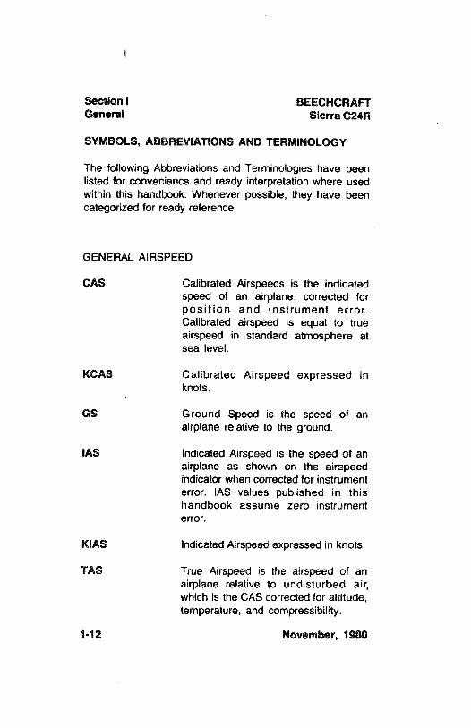
SYMBOLS, ABBREVIATIONSAND TERMINOLOGY
The following Abbreviations and Terminologies have beenlisted for convenience and ready interpretation where usedwithin this handbook. Whenever possible, they have beencategorized for ready reference.
GENERAL AIRSPEED
CAS Calibrated Airspeeds is the indicatedspeed of an airplane, corrected forposition and instrument error.Calibrated airspeed is equal to trueairspeed in standard atmosphere atsea level.
KCAS Calibrated Airspeed expressed inknots.
GS Ground Speed is the speed of anairplane relative to the ground.
IAS Indicated Airspeed is the speed of anairplane as shown on the airspeedindicator when corrected for instrumenterror. IAS values published in thishandbook assume zero instrumenterror.
KIAS Indicated Airspeed expressed in knots.
TAS True Airspeed is the airspeed of anairplane relative to undisturbed air,which is the CAS corrected for altitude,temperature, and compressibility.
1-12 November, 1980
BEECHCRAFT Section iSierra C24R General
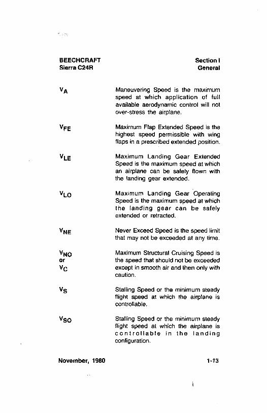
VA Maneuvering Speed is the maximumspeed at which application of fullavailable aerodynamic control will notover-stress the airplane.
VFE Maximum Flap Extended Speed is thehighest speed permissible with wingflaps in a prescribed extended position.
VLE Maximum Landing Gear ExtendedSpeed is the maximum speed at whichan airplane can be safely flown withthe landing gear extended.
VLO Maximum Landing Gear OperatingSpeed is the maximum speed at whichthe landing gear can be safelyextended or retracted.
VNE Never Exceed Speed is the speed limitthat may not be exceeded at any time.
VNO Maximum Structural Cruising Speed isor the speed that should not be exceededVC except in smooth air and then only with
caution.
VS Stalling Speed or the minimum steadyflight speed at which the airplane iscontrollable.
VSO Stalling Speed or the minimum steadyflight speed at which the airplane iscontrollable in the landingconfiguration.
November, 1980 1-13
Section i BEECHCRAFTGeneral Sierra C24R
VX Best Angle-of-Climb Speed is theairspeed which delivers the greatestgain of altitude in the shortest possiblehorizontal distance.
Vy Best Rate-of-Climb Speed is theairspeed which delivers the greatestgain in altitude in the shortest possibletime.
Cruise Cilmb Recommended Climb Speed forenroute climb.
METEOROLOGICAL
ISA International Standard Atmosphere inwhich:(1) The air is a dry perfect gas;(2) The temperature at sea level is
15°
Celsius (59°Fahrenheit);
(3) The pressure at sea level is 29.92inches Hg (1013.2 millibars);(4) The temperature gradient from sealevel to the altitude at which thetemperature is -
56.5°C (-69.7°F) is-0.00198°C (-0.003566°F) per footand zero above that altitude.
OAT Outside Air Temperature is the free airstatic temperature, obtained eitherfrom inflight temperature indicationsadjusted for instrument error andcompressibility effects, or groundmeteorological sources.
1-14 November, 1980
BEECHCRAFT Section iSierra C24R General
Indicated The number actually read from anPressure altimeter when the barometric
Altitude subscale has been set to 29.92 inchesof mercury (1013.2 millibars).
Pressure Altitude measured from standard seaAltitude level pressure (29.92 in. Hg) by a
pressure (barometric) altimeter. It isthe indicated pressure altitudecorrected for position and instrumenterror. In this handbook, altimeterinstrument errors are assumed to bezero. Position errors may be obtainedfrom the Altimeter Correction graph.
Station Actual atmospheric pressure at fieldPressure elevation.
Wind The wind velocities recorded asvariables on the charts of thishandbook are to be understood as theheadwind or tailwind components ofthe reported winds.
POWER
Take-off and Highest power rating not limited byMaximum time.Continuous
ENGINE CONTROLS AND INSTRUMENTS
Throttle Control Used to control power by introducingfuel-air mixture into the intakepassages of the engine. Settings arereflected by readings on the manifoldpressure gage.
November, 1980 1-15
Section i BEECHCRAFTGeneral Sierra C24R
Propeller Control This control requests the propellergovernor to maintain engine/propellerrpm at a selected value by controllingpropeller blade angle.
Mixture Control This control is used to set fuel flow inall modes of operation and cuts off fuelcompletely for engine shut down.
EGT(Exhaust Gas This indicator is used to identify theTemperature) lean and best power fuel flow mixturesindicator for various power settings.
Tachometer Indicates the rpm of theengine/propeller.
Propeller Regulates the rpm of theGovernor engine/propeller by increasing or
decreasing the propeller pitch througha pitch change mechanism in thepropeller hub.
AIRPLANE PERFORMANCE AND FLIGHT PLANNING
Climb Gradient The ratio of the change in heightduring a portion of a climb, to thehorizontal distance traversed in thesame time interval.
Demonstrated The demonstrated crosswind velocityCrosswind is the velocity of the crosswindVelocity component for which adequate control
of the airplane during take off andlanding was actually demonstratedduring certification tests.
1-16 November, 1980
BEECHCRAFT Section iSierra C24R General
MEA Minimum enroute IFR altitude.
Route Segment A part of a route. Each end of that partis identified by: (1) a geographicallocation; or (2) a point at which adefinite radio fix can be established.
GPH U.S. Gallons per hour.
PPH Pounds per hour.
WEIGHT & BALANCE
Reference Datum An imaginary vertical plane from whichall horizontal distances are theasuredfor balance purposes.
Station A location along the airplane fuselageusually given in terms of distance fromthe reference datum.
Arm The horizontal distance from thereference datum to the center ofgravity (C.G.) of an item.
Moment The product of the weight of an itemmultiplied by its arm (Moment divideaby a constant is used to simplifybalance calculations by reducing thenumber of digits.)
Airplane The point at which an airplane wouldCenter of balance if suspended. Its distance fromGravity (CG) the reference datum is found by
dividing the total moment by the totalweight of the airplane.
November, 1980 1-17
Section i BEECHCRAFTGeneral Sierra C24R
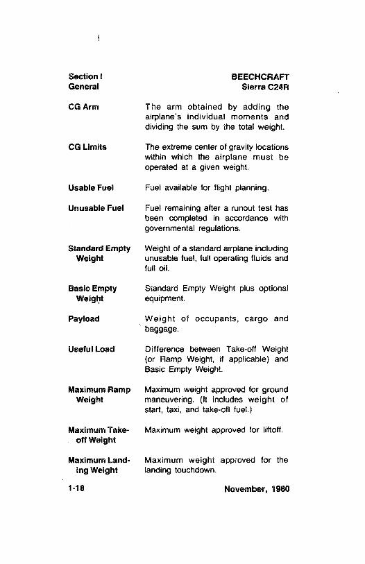
CG Arm The arm obtained by adding theairplane's individual moments anddividing the sum by the total weight.
CG Limits The extreme center of gravity locationswithin which the airplane must beoperated at a given weight.
Usable Fuel Fuel available for flight planning.
Unusable Fuel Fuel remaining after a runout test hasbeen completed in accordance withgovernmental regulations.
Standard Empty Weight of a standard airplane includingWeight unusable fuel, full operating fluids and
full oil.
Basic Empty Standard Empty Weight plus optionalWeight equipment.
Payload Weight of occupants, cargo andbaggage.
Useful Load Difference between Take-off Weight(or Ramp Weight, if applicable) andBasic Empty Weight.
Maximum Ramp Maximum weight approved for groundWeight maneuvering. (It includes weight of
start, taxi, and take-off fuel.)
Maximum Take- Maximum weight approved for liftoff.off Weight
Maximum Land- Maximum weight approved for theIng Weight landing touchdown.
1-18 November, 1980
BEECHCRAFT Section iSierra C24R General
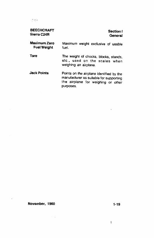
Maximum Zero Maximum weight exclusive of usableFuel Weight fuel.
Tare The weight of chocks, blocks, stands,etc., used on the scales whenweighing an airplane.
Jack Points Points on the airplane identified by themanufacturer as suitable for supportingthe airplane for weighing or otherpurposes.
November, 1980 1-19

BEECHCRAFTSierra 200 C24R
SECTION II
LIMITATIONS
TABLE OF CONTENTS
SUBÆCT PAGE
Airspeed Limitations ........................... .. .........................
2-3Airspeed indicator Markings .............................................
2-4Power Plant Limitations
Engine............................ ............................
2-4Operating Limitations.................................................2-5Fuel Grades.......................... . . ................:.........
2-5Fuel Additives.............................. . ...........................
2-5Oil Specifications........................... .........................
2-5Propeller Specifications................................................. 2-6
Power Plant Instrument Markings .....................................
2-6Miscellaneous Instrument Markings.................................. 2-7Weight Limits ........................... . .... . .........................
2-7Center of Gravity Limits..................................................... 2-7Reference Datum........................... . ..........................
2-7Maneuver Limits ................................... ...........................
2-7Approved Maneuvers (2750 Pounds)............................ 2-8
Flight Load Factors (2750 Pounds)................................... 2-8Takeoff........................... .. ..........................
2-8Minimum Flight Crew ........................................................
2-8Kinds of Operation Limits.................................................. 2-8Equipment Required for Various
Conditionsof Flight........................... ..........................
2-8Fuel
Total Fuel ......................... ...........................2-20
Fuel Management ........................... ...........................
2-20Placards......................... ........................
2-21
November, 1980 2-1
Section il BEECHCRAFTLimitations Sierra C24R
The limitations included in this section have been approvedby the Federal Aviation Administration and must beobserved in the operation of this airplane.
2-2 November, 1980
BEECHCRAFT Section 11Sierra C24R Limitations
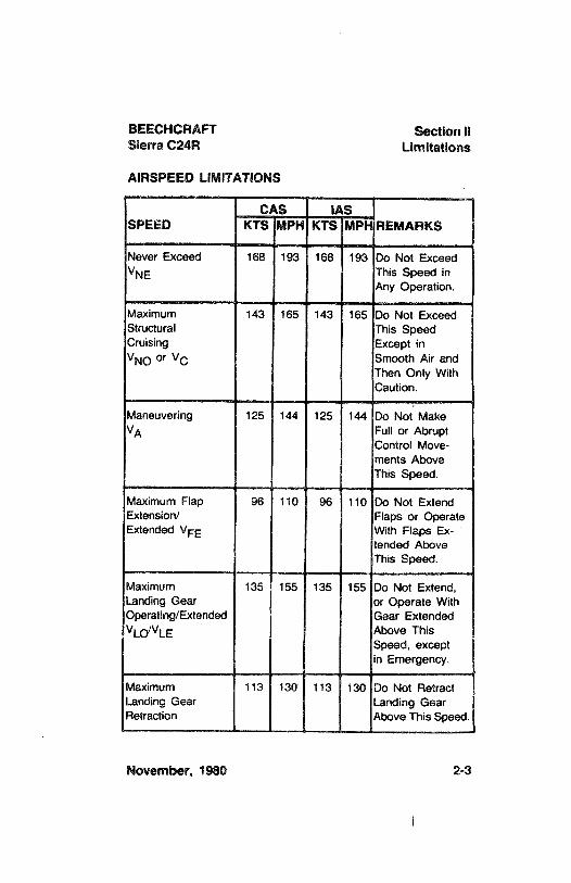
AIRSPEED LIMITATIONS
CAS IASSPEED REMARKS
Never Exceed 168 193 168 193 Do Not ExceedNE This Speed in
Any Operation.
Maximum 143 165 143 165 Do Not ExceedStructural This SpeedCruising Except inVNOor VC Smooth Air and
Then Only WithCaution.
Maneuvering 125 144 125 144 Do Not MakeVA Full or Abrupt
Control Move-ments AboveThis Speed.
Maximum Flap 96 110 96 110 Do Not ExtendExtension/ Flaps or OperateExtended VFE With Flaps Ex-
tended AboveThis Speed.
Maximum 135 155 135 155 Do Not Extend,Landing Gear or Operate WithOperating/Extended Gear ExtendedVLO LE Above This
Speed, exceptin Emergency.
Maximum 113 130 113 130 Do Not RetractLanding Gear Landing GearRetraction Above This Speed.
November, 1980 2-3
Section 11 BEECHCRAFTLimitations Sierra C24R
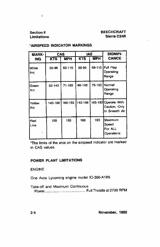
*AIRSPEED INDICATOR MARKINGS
MARK- CAS 11S SIGNIF1-ING KTS MPH KTS MPH CANCE
White 55-96 63-110 60-96 69-110 Full FlapArc Operating
Range
Green 62-143 71-165 65-143 75-165 NormalArc Operating
Range
Yellow 143-168 165-193 143-168 165-193 Operate WithArc Caution, Only
in Smooth Air
Red 168 193 168 193 MaximumLine Speed
For ALLOperations
*The limits of the arcs on the airspeed indicator are markedin CAS values.
POWER PLANT LIMITATIONS
ENGINE
One Avco Lycoming engine model IO-360-A186
Take-off and Maximum ContinuousPower......................................... Full Throttle at 2700 RPM
2-4 November, 1980
BEECHCRAFT Section 11Sierra C24R Limitations
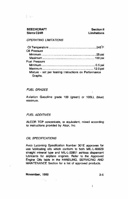
OPERATINGLIMITATIONS
OilTemperature .......................... ...........................
245°F
Oil PressureMinimum ......................... . . ...........................25 psiMaximum ....................... .. . ........................... 100 psi
Fuel PressureMinimum ......................... ........................0.5 psiMaximum ......................... ..................................... 12.0 psiMixture - set per leaning instructions on Performance
Graphs.
FUEL GRADES
Aviation Gasoline grade 100 (green)or 100LL (blue)minimum.
FUEL ADD/T/VES
ALCOR TCP concentrate, or equivalent, mixed accordingto instructions provided by Alcor, Inc.
O/L SPECIFICAT/ONS
Avco Lycoming Specification Number 301E approves foruse lubricating oils which conform to both MIL-L-6082Bstraight mineral type and MIL-L-22851 ashless dispersantlubricants for airplane engines. Refer to the ApprovedEngine Oils table in the HANDLING,SERVICING ANDMAINTENANCE Section for a list of approved products.
November, 1980 2-5
Section 11 BEECHCRAFTLimitations Sierra C24R
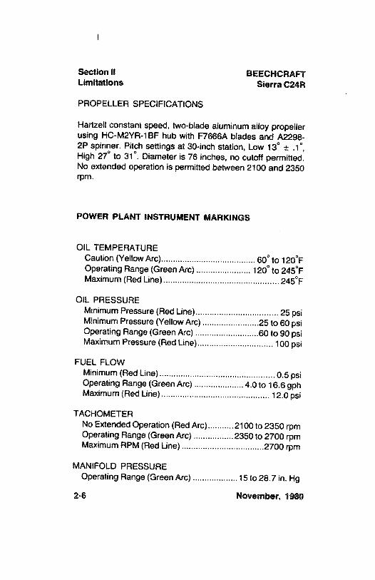
PROPELLER SPECIFICATIONS
Hartzell constant speed, two-blade aluminumalloy propellerusing HC-M2YR-1BF hub with F7666A blades and A2298-
2P spinner. Pitch settings at 30-inch station, Low 13°±
.1°,
High 27° to 31°.Diameter is 76 inches, no cutoff permitted.
No extended operation is permitted between 2100 and 2350rpm.
POWER PLANT INSTRUMENT MARKINGS
OIL TEMPERATURECaution (Yellow Arc)........................................ 60° to 120°F
Operating Range (Green Arc) .......................
120° to 245°F
Maximum (Red Line)................................................245°F
OIL PRESSUREMinimum Pressure (Red Line)................................... 25 psiMinimum Pressure (Yellow Arc) ........................25 to 60 psiOperating Range (Green Arc) ...........................60 to 90 psiMaximum Pressure (Red Line)................................ 100 psi
FUEL FLOWMinimum (Red Line)...................... . .......................0.5 psiOperating Aange (Green Arc) .....................4.0 to 16.6 gphMaximum (Red Line).............................................. 12.0 psi
TACHOMETERNo Extended Operation (Red Arc)...........2100 to 2350 rpmOperating Range (Green Arc) .................2350 to 2700 rpmMaximum RPM (Red Line) ...................................2700 rpm
MANIFOLD PRESSUREOperating Range (Green Arc) ...................15 to 28.7 in. Hg
2-6 November, 1980
BEECHCRAFT Section 11Sierra C24R Limitations
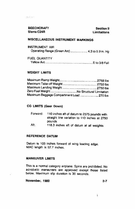
MISCELLANEOUSINSTRUMENT MARKINGS
INSTRUMENT AIROperating Range (Green Arc) ....................4.3 to 5.9 in. Hg
FUEL QUANTITYYellow Arc...................... . ..................... E to 3/8 Full
WEIGHT LIMITS
Maximum Ramp Weight............................................ 2758 IbsMaximum Take-off Weight........................................ 2750 lbsMaximum Landing Weight ........................................ 2750 lbsZero Fuel Weight ...............................No Structural LimitationMaximum Baggage Compartment Load ...................,. 270 lbs
CG LIMITS(Gear Down)
Forward: 110 inches aftof datum to 2375 pounds withstraight line variation to 113 inches at 2750pounds
Aft: 118.3 inches aft of datum at all weights
REFERENCE DATUM
Datum is 103 inches forward of wing leading edge.MAC length is 52.7 inches.
MANEUVER LIMITS
This is a normal category airplane. Spins are prohibited. Noacrobatic maneuvers are approved except those listedbelow. Maximum slip duration is 30 seconds.
November, 1980 2-7
Section 11 BEECHCRAFTUmitations Sierra C24R
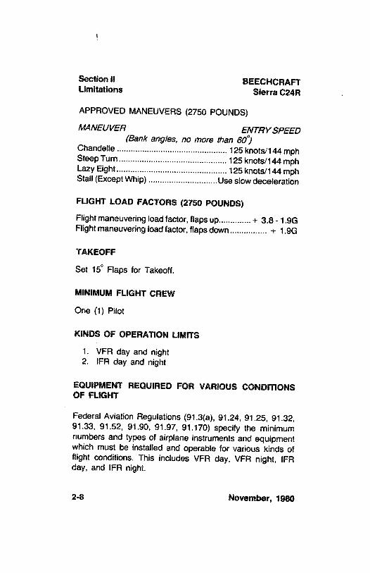
APPROVED MANEUVERS(2750 POUNDS)
MANEUVER ENTRY SPEED(Bank angles, no more than 60°J
Chandelle ................................................ 125 knots/144 mphSteep Turn............................................... 125 knots/144 mphLazy Eight................................................ 125 knots/144 mphStall (Except Whip) ..............................Use slow deceleration
FLIGHT LOAD FACTORS (2750 POUNDS)
Flight maneuvering load factor, flaps up..............+ 3.8 - 1.9GFlight maneuvering load factor, flaps down................ + 1.9G
TAKEOFF
Set 15°Flaps for Takeoff.
MINIMUM FLIGHT CREW
One (1) Pilot
KINDSOF OPERATION LIMITS
1. VFR day and night2. IFR day and night
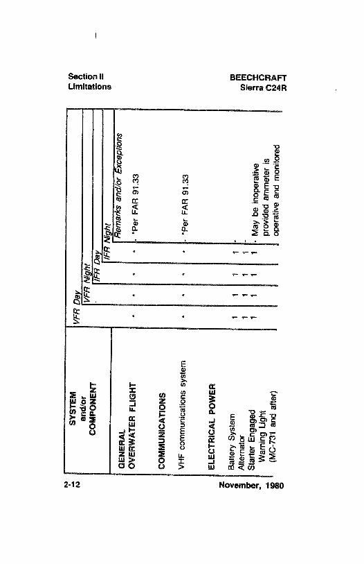
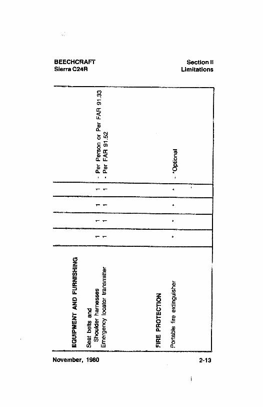
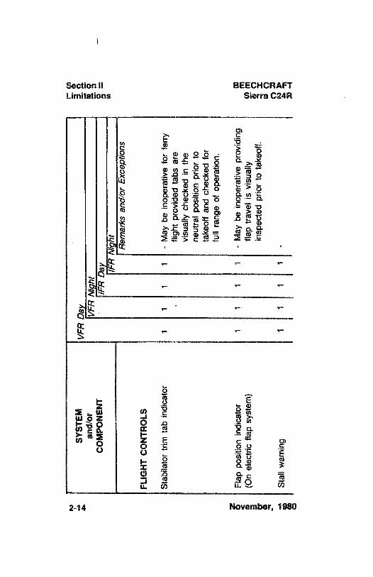
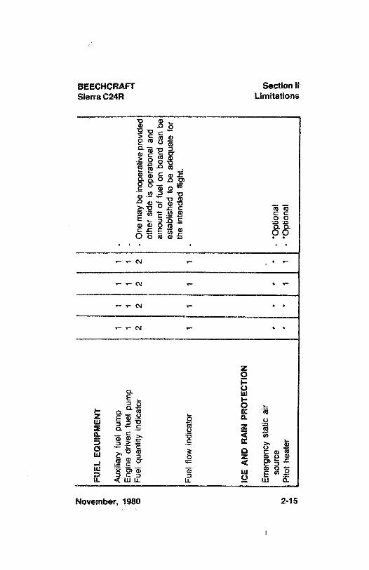
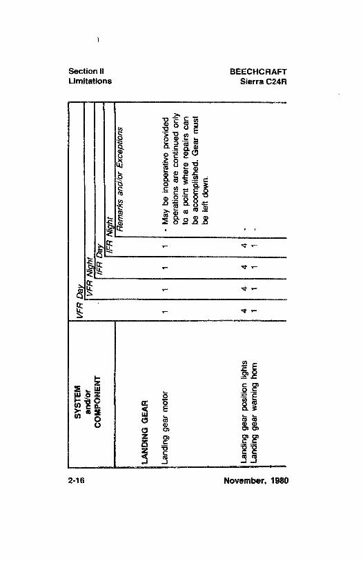
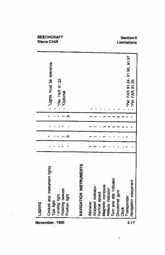
EOUIPMENT REQUIRED FOR VARIOUSCONDITIONSOF FUGHT
Federal Aviation Regulations (91.3(a), 91.24, 91.25, 91.32,91.33, 91.52, 91.90, 91.97, 91.170) specify the minimumnumbers and types of airplane instruments and equipmentwhich must be installed and operable for various kinds offlight conditions. This includes VFR day, VFR night, IFRday, and IFR night.
2-8 November, 1980
BEECHCRAFT Section IISierra C24R Limitations
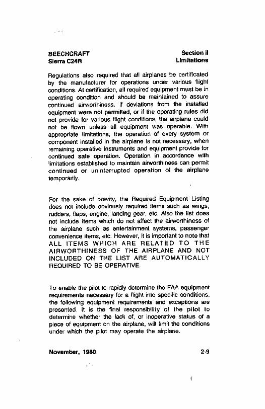
Regulations also required that all airplanes be certificatedby the manufacturer for operations under various flightconditions.At certification,all required equipment must be inoperating condition and should be maintained to assurecontinued airworthiness. If deviations from the installedequipment were not permitted, or if the operating rules didnot provide for various flight conditions, the airplane couldnot be flown unless all equipment was operable. Withappropriate limitations, the operation of every system orcomponent installed in the airplane is not necessary, whenremaining operative instruments and equipment provide forcontinued safe operation. Operation in accordance withlimitations established to maintain airworthiness can permitcontinued or uninterrupted operation of the airplanetemporarily.
For the sake of brevity, the Required Equipment Listingdoes not include obviously required items such as wings,rudders, flaps, engine, landing gear, etc. Also the list doesnot include items which do not affect the airworthiness ofthe airplane such as entertainment systems, passengerconvenience items, etc. However, it is important to note thatALL ITEMS WHICH ARE RELATED TO THEAIRWORTHINESS OF THE AIRPLANE AND NOTINCLUDED ON THE LIST ARE AUTOMATICALLYREQUIRED TO BE OPERATIVE.
To enable the pilot to rapidly determine the FAA equipmentrequirements necessary for a flight into specific conditions,the following equipment requirements and exceptions arepresented. It is the final responsibility of the pilot todetermine whether the lack of, or inoperative status of apiece of equipment on the airplane, will limit the conditionsunder which the pilot may operate the airplane.
November, 1980 2-9
Section 11 BEECHCRAFTLimitations Sierra C24R
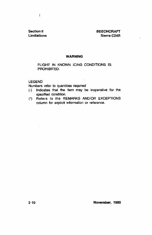
WARNING
FLIGHT IN KNOWN ICING CONDITIONSISPROHIBITED.
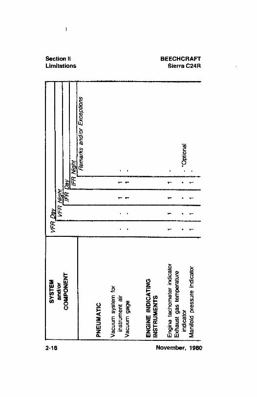
LEGENDNumbers refer to quantities required(-) Indicates that the item may be inoperative for the
specified condition.(*) Refers to the REMARKS AND/OR EXCEPTIONS
column for explicit information or reference.
2-10 November, 1980

BEECHCRAFT Section 11Sierra C24R Limitations
INTENTIONALLY LEFT BLANK
November, 1980 2-11
SYST
EM¥P
RD
ayan
d/or
VFR
Níg
htC
OM
PON
ENT
IFR
Day
g=
IFR
Vig
hte
Rem
arks
and/
orEx
cept
ions
GEN
ERA
LO
VER
WA
TER
FLIG
HT
**
**
-
*Per
FAR
91.3
3
CO
MM
UN
ICA
TIO
NS
VH
Fco
mm
unic
atio
nssy
stem
**
**
-
*Per
FAR
91.3
3
ELEC
TRIC
AL
POW
ER
Bat
tery
Syst
em1
11
1A
ltern
ator
11
11
-
gmSt
arte
rEn
gage
d1
11
1-
May
bein
oper
ativ
e|
I
War
ning
Ligh
tpr
ovid
edam
met
eris
om(M
C-7
31an
daf
ter)
oper
ativ
ean
dm
onito
red
zem
oem
EOU
IPM
ENT
AN
DFU
RN
ISH
ING
Seat
belts
and
Shou
lder
harn
esse
s1
11
1-
Per
Pers
onor
Per
FAR
91.3
3Em
erge
ncy
loca
tor
trans
mitt
er1
11
1-
Per
FAR
91.5
2
FIR
EPR
OTE
CTI
ON
Porta
ble
fire
extin
guis
her
**
**
-*O
ptio
nal
SYST
EMV
FRJa
V:::
ean
d/or
VFR
Vip
hti
ÊC
OM
PON
ENT
/FR
Day
Ê-
/FR
Vig
hte
Rer
nark
san
d/or
Exce
ptio
ns
FLIG
HT
CO
NTR
OLS
Stab
ilato
rtri
mta
bin
dica
tor
i1
11
-
May
bein
oper
ativ
efo
rfe
rry
fligh
tpr
ovid
edta
bsar
evi
sual
lych
ecke
din
the
neut
ral
posi
tion
prio
rto
take
offa
ndch
ecke
dfo
rfu
llra
nge
ofop
erat
ion.
z oFl
appo
sitio
nin
dica
tor
11
11
-
May
bein
oper
ativ
epr
ovid
ing
m(O
nel
ectri
cfla
psy
stem
)fla
ptra
veli
svi
sual
ly9
min
spec
ted
prio
rto
take
off.
|xSt
all w
arni
ng1
11
1-
N>
z(n
a
iFU
ELEO
UIP
MEN
Tm
g
Aux
iliar
yfu
elpu
mp
11
11
-
Engi
nedr
iven
fuel
pum
p1
11
1-
Fuel
quan
tity
indi
cato
r2
22
2-
One
may
bein
oper
ativ
epr
ovid
edot
her
side
isop
erat
iona
land
amou
ntof
fuel
onbo
ard
can
bees
tabl
ishe
dto
bead
equa
tefo
rth
ein
tend
edfli
ght.
Fuel
flow
indi
cato
r1
11
1-
ICE
AN
DR
AIN
PRO
TEC
TIO
N
Emer
genc
yst
atic
air
-
iy
sour
ce*
**
*-
*Opt
iona
li
(Pi
tot
heat
er*
*1
1-
*Opt
iona
li
g
SYST
EMV
FRO
ay(
ean
d/or
VFR
Nig
htg
5C
OM
PON
ENT
-
IFR
v
/FR
Nig
htR
emar
ksan
d/or
Exce
ptio
ns
LAN
DIN
GG
EAR
Land
ing
gear
mot
or1
11
1-
May
bein
oper
ativ
epr
ovid
edop
erat
ions
are
cont
inue
don
lyto
apo
int
whe
rere
pairs
can
beac
com
plis
hed.
Gea
rm
ust
bele
ftdo
wn.
Land
ing
gear
posi
tion
light
s4
44
4-
Land
ing
gear
wam
ing
hom
i1
11
-,
I
zom
oLI
GH
TSi
mm
gC
ockp
itan
din
stru
men
tlig
hts
-
*-
*-
*Lig
hts
mus
tbe
oper
ativ
e.."
Taxi
light
--
--
-
gLa
ndin
glig
ht-
*-
*-
*Per
FAR
91.3
38
Rot
atin
gbe
acon
*1
*1
-*O
ptio
nal
Posi
tion
light
-
3-
3
NA
VIG
ATI
ON
INST
RU
MEN
TS
Alti
met
er1
11
1-
Airs
peed
indi
cato
r1
11
1-
Ver
tical
spee
d-
--
--
Mag
netic
com
pass
11
11
-
Atti
tude
indi
cato
r-
-1
1-
Turn
and
slip
indi
cato
r-
-
11
-
Dire
ctio
nal
gyro
--
1-1
-C
Clo
ck-
-
11
-
Tran
spon
der
**
**
-
*Per
FAR
91.2
4,91
.90,
91.9
7Ë
gN
avig
atio
neq
uipm
ent
--
**
-
*Per
FAR
91.3
3=
|
SYST
EMV
PRO
gB
oan
d/or
VPR
Nig
hty
5C
OM
PON
ENT
-
IFR
Qav /F
RN
ight
Rem
arks
and/
orEx
cept
ions
PNEU
MA
TIC
Vac
uum
syst
emfo
rin
stru
men
tai
r-
-
11
-
Vac
uum
gage
--
11
-
ENG
INE
IND
ICA
TIN
Gz
INST
RU
MEN
TSo
Engi
neta
chom
eter
indi
cato
r1
11
1-
gEx
haus
tga
ste
mpe
ratu
re.,
indi
cato
r*
**
*-
*Opt
iona
l
gM
anifo
ldpr
essu
rein
dica
tor
11
11
-
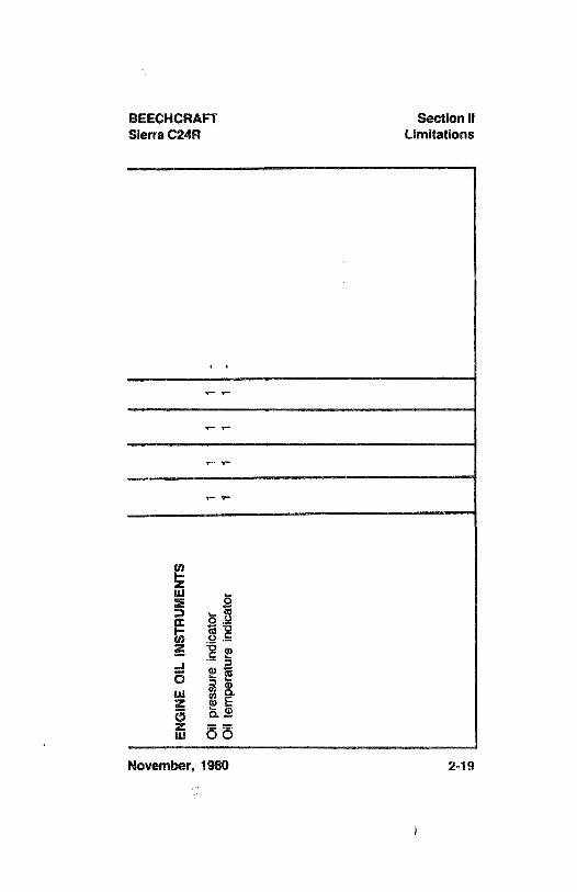
BEECHCRAFT Section 11Sierra C24R Limitations
a a
z oE
z = =
m OO
November, 1980 2-19
Section 11 BEECHCRAFTLimitations Sierra C24R
FUEL
TOTAL FUEL with left and right wing fuel systems full:
Capacity......................... . .. .......................59.8
gallons*Usable ........................... . ............................. 57.2 gallons
*Value given is nominal. Tank capacity will vary with tem-perature and manufacturing tolerances.
FUEL MANAGEMENT
Do not take off when Fuel Quantityindicators indicate in theyellow band on either indicator.
Maximum slip duration is 30 seconds.
2-20 November, 1980
BEECHCRAFT Section 11Sierra C24R Limitations
PLACARDS
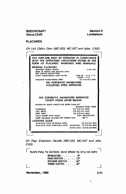
On Left Cabin Door (MC-533, MC-537 and after, CAS)
| THIS AIRPLANEMUST BE OPERATEDIN COMPLIANCEWITH THE OPERATING UMITATIONS STATEDIN THEFORM OF PLACARDS, MARKINGS AND MANUALS.NORMAL CATEGORY
MAXIMUM DESIGN WEIGHT 2750 LBSREFER TO WEIGHT AND BALANCE DATAFOR LOADING INSTRUCTIONSFLIGHT MANEUVEttNG LOAD FACTOR FLAPS UP +38 -1.9
DOWN +19MAXIMUM MANEUVERING SPEED 125 KTS/144 MPH
NO ACROBATIC MANEUVERSINCLUDING SPINS APPROVED
NO ACROBATIC MANEUVERSAPPROVEDEXCEPTTHOSE LISTEDBELOW:
MANEUVER, BANK ANGLES NO MORE THAN 60°
MAXIMUM ENTRY SPEEDCHANDELLES 125 KTS/144 MPHLAZY EIGHTS 125 KTS/144 MPHSTEEP TURN$ 125 KIS/144 MPHSTALLS (EXCEPT WHIP STALLSI SLOW DECELERATIONNOTE: MAXIMUM ALTITUDE LOSS DURINGSTALL 300 FT
LANDING GEARMAXIMUM GEAR EXTENDED SPEED 135 KTS/155 MPHMAxiMUM GEAR OPERATING SPEED EXTENSION 135 KTS/155 MPH
RETRACTION !!3 KTS/130 MPH
On Flap Extension Handle (MC-533, MC-537 and after,CAS)
FLAPS PULL TO EXTEND, MAX SPEED 96 KTS/llO MPHRETRACTED. . . . . . .
0°FIRSTNOTCH . . . . . .
15*SECOND NOTCH . . . .
25°THIRDNOTCH . . . . .
35°
November, 1980 2-21
Section 11 BEECHCRAFTLimitations Sierra C24R
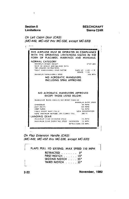
On Left Cabin Door (CAS):(MC-449, MC-452 thru MC-536, except MC-533)
THIS AIRPLANE MUST BE OPERATED IN COMPLIANCEWITH THE OPERATING LIMITATIONS STATED IN THEFORM OF PLACARDS, MARKINGS AND MANUALS.
NORMAL CATEGORYMAKIMUM DE51GN WEIGHT 2750 LBSREFER TO WEIGHT AND BALANCE DATAFOR LOADING INSTRUCTIONS
FLIGHT MANEUVERING LOAD FACTOR FLAPS UP + 3 8 - 1 9DOWN + 1 9
MAXIMUM MANEUVERING SPEED 144 MPH
NO ACROBATICMANEUVERSINCLUDING SPINS APPROVED
NO ACROBATic MANEUVERSAPPROVEDEXCEPT THOSE LISTEDBELOW:
MANEUVER BANK ANGLES NO MORE THAN 60
MAXIMUM INTRY SPEEDCHANDELLES 144 MPH
,tAZY EIGHTS 144 MPH
STEEP TURNS 144 MPH
STAtt5 IEXCEPT WHIP STALLS: SLOW DECELERATION
NOTE MAXIMUM ALTITUDE LOSS DURING STAtt 300 FT
LANDING GEARMAXIMUM OfAR fxifNDED SPEED ISS MPH
MAxtMUM GEAR OPERAllNG SPEED EXIENSION 155 MPH
RETRACTION 130 MPH
On Flap Extension Handle (CAS):(MC-449, MC-452 thru MC-536, except MC-533)
FLAPS PULL TO EXTEND, MAX SPEED 110 MPHRETRACTED . . . . . . .
0°FIRST NOTCH . . . . . .
15°
SECODNDNOCTHCH. . . .
2-22 November, 1980
BEECHCRAFT Section 11Sierra C24R Limitations
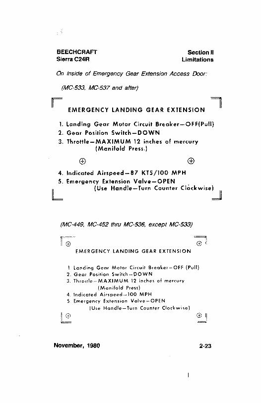
On /nside of Ernergency Gear Extensíon Access Door:
(MC-533, MC-537 and after)
EMERGENCY LANDING GEAR EXTENSION
1. Landing Gear Motor Circuit Breaker-OFF(Pull)2. Gear Position Switch-DOWN3. Throttle-MAXIMUM 12 inches of mercury
(Manifold Press.)
4. Indicated Airspeed-87 KTS/100 MPH5. Emergency Extension Valve-OPEN
(Use Handle-Turn Counter Clockwise)L J
(MC-449,MC-452 thru MC-536, except MC-533)
EMERGENCY LANDING GEAR EXTENSION
l Landing Gear Motor Circuit Breaker-OFF (Pull)2 Gear Position Switch-DOWN
3 Throule-MAXIMUM 12 inches of mercury
(Manifold Press)4 Indicated Airspeed-100 MPH5 Emergency Extension Valve-OPEN
(Use Haridle-Turn Counter Clockwise)
L TJ
November, 1980 2-23
Section il BEECHCRAFTLimitations Sierra C24R
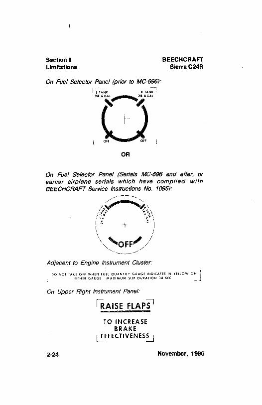
On Fuel Selector Panel (prior to MC-696):
L TANK R TAN
OFF OFF
OR
On Fuel Selector Panel (Serials MC-696 and after, orearlier airplane serials which have complied withBEECHCRAFT Service Instructions No. 1095):
OFF
Adjacent to Engine Instrument Cluster
DO NOT IAKE OFF WHEN FUEL QUANTlTY GAUGE INDICATES IN YELLOW ONfifHER GAUGE MAXIMUM SLtP DURATION 30 SEC
On Upper Right Instrument Panel
RAISE FLAPS
TO INCREASEBRAKE
EFFECTIVENESS
2-24 November, 1980
BEECHCRAFT Section 11Sierra C24R Limitations
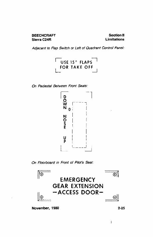
Adjacent to Flap Switch or Left of Quadrant Control Panel:
E¯ ¯l
USE 15° FLAPSFOR TAKE OFF
L_ . J
00 Pedestal Between Front Seats:
OW
[¯ ¯
NO
NoS
uP
On Floorboard in Front of Pilot's Seat:
oEMERGENCY
GEAR EXTENSION
o-ACCESS DOOR-
November, 1980 2-25
Section 11 BEECHCRAFTLimitations Sierra C24R
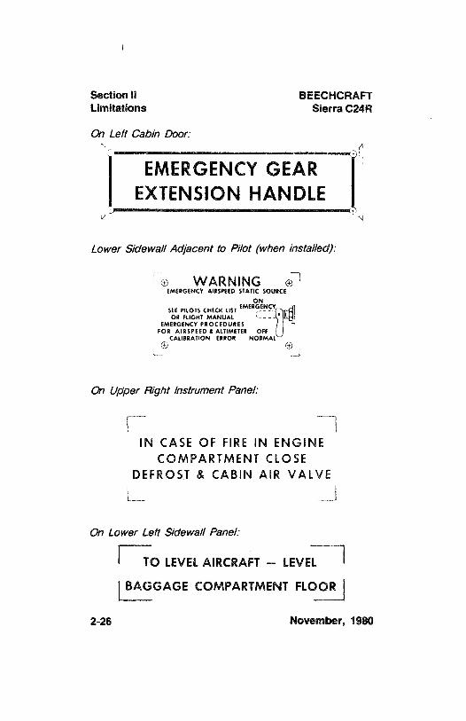
On Left Cabin Door:
EMERGENCY GEAREXTENSIONHANDLE
Lower Sidewall Adjacent to Pilot (when installed)
o WARNING eEMERGENCY AIRSPEED STATIC SOURCE
ONSEE PILOTS CHECK LIST EMERGENC
OR FLIGHT MANUAL ---
EMERGENCY PROCEDURESFOR AIRSPEED A ALTIMETER OFF
CAL18RATION ERROR NORMAL
On Upper Right Instrument Panel:
IN CASE OF FIRE IN ENGINECOMPARTMENT CLOSE
DEFROST & CABIN AIR VALVE
On Lower Left Sidewall Panel
O LEVELAIRCRAFT - LEVEL
BAGGAGE COMPARTMENT FLOOR
2-26 November, 1980
BEECHCRAFT Section 11Sierra C24R Limitations
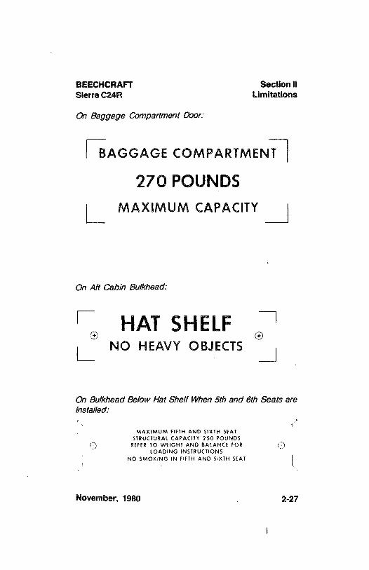
On Baggage Compartrnent Door:
AGGAGE COMPARTMEN
270 POUNDSMAXIMUM CAPACITY
On Aft Cabin Bulkhead:
HAT SHELFNO HEAVY OBJECTS
On Bulkhead Below Hat Shelf When Sth and 6th Seats areInstalled:
MAXIMUM FIFTH AND SIXTH SEATSTRUCTURAL CAPACITY 250 POUNDS
REFER TO WEIGHT AND BALANCE FOR )LOADING INSTRUCTIONS
NO SMOKING IN FIFTH AND SlXTH SEAT
November, 1980 2-27
Section 11 BEECHCRAFTLimitations Sierra C24R
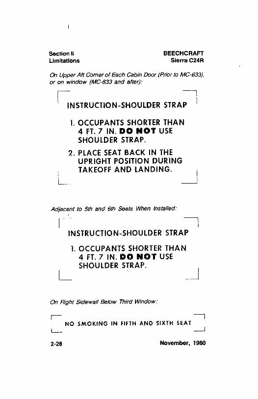
On Upper Aft Corner of Each Cabin Door (Prior to MC-633),or on window (MC-633 and after):
INSTRUCTION-SHOULDERSTRAP
l. OCCUPANTS SHORTERTHAN4 FT. 7 IN. DO NOT USESHOULDER STRAP.
2. PLACE SEATBACK IN THEUPRIGHT POSITION DURINGTAKEOFFAND LANDING.
Adjacent to Sth and 6th Seats When Installed:
INSTRUCTION-SHOULDERSTRAP
l. OCCUPANTS SHORTERTHAN4 FT. 7 IN. DO NOT USESHOULDER STRAP.
On Right Sidewall Below Third Window:
NO SMOKING IN FIFTH AND SIXTH SEATL-- ---J
2-28 November, 1980
BEECHCRAFT Section 11Sierra C24R Limitations
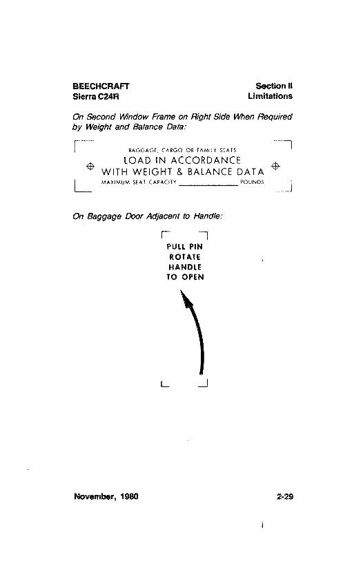
On Second Window Frame on Right Side When Requiredby Weight and Balance Data:
BAGGAGE, CARGO OR FAMILY SEATS
LOAD IN ACCORDANCEWITH WEIGHT & BALANCE DATAMAXIMUM SEAT CAPACITY POUNDS
On Baggage Door Adjacent to Handle:
PULL PINROTATEHANDLE
TO OPEN
November, 1980 2-29

BEECHCRAFTSierra C24R
SECTION III
EMERGENCY PROCEDURESTABLE OF CONTENTS
SUBJECT PAGE
Emergency Airspeeds......................... ......................3-3
Engine FailureDuring Take-Off Ground Roll......................................... 3-4After LiftoffAnd in Flight ................................................
3-4Engine Discrepancy Checks
Rough Running Engine..............................................3-5Loss Of Engine Power ...............................................
3-5Airstart Procedure......................... .......................3-6
Engine FireIn Flight ......................... ........................
3-6On The Ground ......................... .........................
3-7Emergency Descent ........................ .. .. ........................
3-7Maximum Glide Configuration...........................................3-7Landing Emergencies
Landing Without Power .................................................
3-8Landing Gear Retracted - With Power ...........................
3-8Systems Emergencies
Propeller Overspeed.....................................................3-9Starter Engaged Warning Light lituminated................... 3-9Altemator-OutProcedure............................................ 3-10Unscheduled Electric Elevator Trim ............................
3-10Landing Gear Emergency Extension........................... 3-10Landing Gear Retraction After Practice
Manual Extension.......................... . .......................
3-11Emergency Static Air Source System.......................... 3-11Unlatched Door in Flight.............................................. 3-12
Spins..................................... ..........................
3-12Emergency Speed Reduction .........................................
3-12
November, 1980 3-1
Section Ill BEECHCRAFTEmergency Procedures Sierra C24R
INTENTIONALLY LEFT BLANK
3-2 November, 1980
BEECHCRAFT Section IIISierra C24R Emergency Procedures
A// airspeeds quoted in this section are indicatedairspeeds (IAS).
EMERGENCY AIRSPEEDS
Emergency Descent .................................135 KTS/155 MPH
Glide ....................... . .......................91 KTS/105 MPH
Emergency Landing Approach......................74 KTS/85 MPH
Stall warning horn is inoperative when the battery andalternator switches are turned off.
NOTE
On serials MC-696 and after, or on airplaneswhich have complied with BEECHCRAFT S.I.No. 1095, a fuel selector stop has been addedto the selector valve guard. The fuel selectorstop minimizes the possibility of inadvertentlyturning the fuel selector valve to the OFFdetent position. The stop is a spring whichmust be depressed before the selector valvehandle can be rotated to the OFF position.
The following information is presented to enable the pilot toform, in advance, a definite plan of action for coping withthe most probable emergency situations which could occurin the operation of the airplane. Where practicable, theemergencies requiring immediate corrective action aretreated in check list form for easy reference andfamiliarization. Other situations, in which more time isusually permitted to decide on and execute a plan ofaction, are discussed at some length.
November, 1980 3-3
Section III BEECHCRAFTEmergency Procedures Sierra C24R
ENGINE FAILURE
DURING TAKE-OFF GROUND ROLL
1. Throttle - CLOSED2. Braking - MAXIMUM
NOTE
Conduct the following procedures immediately ifit appears certain that the airplane will run offthe runway. (Otherwise, conduct theseprocedures at the pilot's discretion.)
3. Fuel Selector Valve - OFF4. Battery switch, Alternator switch and Magneto/Start
switch - OFF
AFTER LIFTOFF AND IN FLIGHT
Landing straight ahead is usually advisable. // sufficientaltitude is available for maneuvering, accomplish thefo//owing:
1. Mixture - FULL RICH2. Fuel Boost Pump - ON3. Fuel Selector Valve - SELECT OTHER TANK (feel for
detent, and check visually)4. Magnetos - CHECK LEFT AND RIGHT, THEN BOTH
NOTE
The most probable cause of engine failurewould be loss of fuel flow or improperfunctioning of the ignition system.
3-4 November, 1980
BEECHCRAFT Section IIISierra C24R Emergency Procedures
if No Restart:
1. Establish Maximum Glide Configuration2. Throttle - CLOSED3. Fuel Selector Valve - OFF4. Mixture - IDLE CUT-OFF5. Magneto/Start Switch - OFF
When certain of reaching the selected landing site:
6. Airspeed - NORMAL APPROACH SPEED7. Flaps - AS REQUIRED8. Landing Gear - DOWN or UP (depending on terrain)9. Battery switch, alternator switch, and Fuel Boost
Switch - OFF
ENGINE DISCREPANCY CHECKS
CONDITION: ROUGH RUNNINGENGINE
1. Mixture - FULL RICH, then LEAN as required2. Magneto/Start Switch - CHECK LEFT, RIGHT, THEN
BOTH
CONDITION: LOSS OF ENGINE POWER
1. Fuel Flow Gage - CHECK
// fuel flow is abnorma//y low:a. Mixture - FULL RICHb. Auxiliary Fuel Pump - ON (Lean as required)c. Auxiliary Fuel Pump - OFF if performance does
not improve in a few moments
November,1980 3-5
Section III BEECHCRAFTEmergency Procedures Sierra C24R
2. Fuel Quantity indicator - CHECK for fuel supply in tankbeing used
// tank being used is empty:Fuel Selector Valve - SELECT OTHER FUEL TANK(feel for detent, and check visually)
AIR START PROCEDURE
1. Fuel Selector Valve - SELECT TANK MORE NEARLYFULL (Check to feel detent and check visually.)
2. Throttle - AS REQUIRED3. Mixture - FULL RICH4. Propeller - AS REQUIRED5. Fuel Boost Pump - ON OR OFF as required6. Magneto/Start Switch - BOTH
NOTE
When engine starts, adjust throttle, propeller,and mixture controls.
ENGINE FIRE
IN FLIGHT
The red FIREWALL AIR controls must be closed to shut offall heating system outlets so that smoke and fumes will notenter the cabin. The control labeled CABIN AIR, on the leftof the power control quadrant, must be pulled att to close.The control labeled DEFROST, to the right of the powercontrol quadrant, must be pushed fonward to close. In theevent of an engine fire, shut down the engine as follows andmake a landing:
3-6 November, 1980
BEECHCRAFT Section IIISierra C24R Emergency Procedures
1. Fuel Selector Valve - OFF2. Mixture - IDLE CUT-OFF3. Propeller - FULL FORWARD (High rpm position)4. Throttle - CLOSE5. Cabin Air Control (Red Knob) - pull OFF6. Defrost Valve (Red Knob) - push OFF7. Alternator Switch - OFF8. Battery Switch - OFF (Extending the gear can be
accomplished manually if desired)9. Magneto/Start Switch - OFF
10. Do not attempt to restart engine
ON THE GROUND
1. Fuel Selector Valve - OFF2. Throttle - CLOSE3. Mixture - IDLE CUT-OFF4. Battery Switch and Alternator Switch - OFF5. Magneto/Start Switch - OFF6. Fire Extinguisher - USE TO EXTINGUISH FIRE
EMERGENCY DESCENT
1. Propeller - FULL FORWARD (High rpm position)2. Throttle - IDLE3. Landing Gear - DOWN4. Airspeed - ESTABLISH 135 KTS/155 MPH
MAXIMUMGLIDE CONFIGURATION
1. Landing Gear - UP (Landing gear safety switch OFF ifsystem is installed)
2. Flaps - UP3. Propeller - FULL AFT (Low rpm position)4. Airspeed - Establish 91 KTS/105 MPH
Glide distance is approximately 1.7 nautical miles (2 statutemiles) per 1000 feet above the terrain.
November, 1980 3-7
Section III BEECHCRAFTEmergency Procedures Sierra C24R
LANDING EMERGENCIES
LANDING WITHOUT POWER
When assured of reaching the landing site selected, and onfinal approach:
1. Airspeed - EMERGENCY APPROACH SPEED2. Fuel Selector Valve - OFF3. Mixture - IDLE CUT-OFF4. Flaps - AS REQUIRED5. Landing Gear - DOWN or UP, DEPENDING ON
TERRAIN6. Battery Switch and Alternator Switch - OFF
LANDING GEAR RETRACTED - WITH POWER
11possible, choose firm sod or foamed runway. Make anormal approach, using flaps as necessary. When sure ofreaching the selected landing spot:
1. Throttle - CLOSED2. Airspeed - NORMAL APPROACH SPEED3. Fuel Selector Valve - OFF4. Mixture - IDLE CUT-OFF5. Flaps - AS REQUIRED6. Battery Switch and Alternator Switch - OFF7. Keep wings level during touchdown8. Get clear of airplane as soon as possible after it stops:
3-8 November, 1980
BEECHCRAFT Section IIISierra C24R Emergency Procedures
SYSTEMS EMERGENCIES
PROPELLER OVERSPEED
1. Throttle - RETARD TO MINIMUM CRUISE RPM2. Airspeed - REDUCE (Initiate climb to load propeller if
time permits.)3. Oil Pressure - CHECK
WARNING
If loss of oil pressure was the cause ofoverspeed, the engine may seize after a shortperiod of operation. IF ENGINE FAILS:
4. Land - SELECT NEAREST SUITABLE SITE and followENGINE FAILURE AFTER LIFTOFF AND IN FLIGHTprocedures.
STARTER ENGAGED WARNING LIGHT ILLUMINATED(if Installed)
The STARTER ENGAGED warning light illuminateswhenever the starter is engaged. If this light remainsilluminated after the Magneto/Start Switch is released fromthe START position, the starter relay is still energized.Consequently, electrical power is still being supplied to thestarter, and it remains engaged. Continuing to supplypower to the starter will eventually result in the completeloss of electrical system power, substantial starter damage,and possible damage to other electrical systemcomponents.
If light remains illuminated on the ground:1. BATTERY & ALT and ALT Switches - OFF2. Do Not Take Off.
// /ight remains i//uminated in flight after air start:1. BATTERY & ALT and ALT Switches - OFF2. Land As Soon As Practical.
November, 1980 3-9
Section Ill BEECHCRAFTEmergency Procedures Sierra C24R
ALTERNATOR-OUT PROCEDURE
An inoperative alternator will place the entire electricaloperation of the airplane on the battery. Alternatormalfunction will be indicated by a fluctuation of theammeter needle, or by a discharge indication. If thiscondition develops:
1. ALT Switch - OFF MOMENTARILY, THEN ON (thisresets overvoltage relay)
// alternator-out condition persists:2. ALT Switch - OFF3. Nonessential Electrical Equipment - OFF to conserve
battery power.WARNING
Deactivation of the battery switch, alternatorswitch, or alternator circuit breaker during flightis prohibited, except as required by an actualemergency.
UNSCHEDULED ELECTRICSTABILATOR TRIM1. Airplane Attitude - MAINTAINusing stabilator control2. Stabilator Trim Thumb Switch (on Control Wheel) -
DEPRESS AND MOVE IN DIRECTION OPPOSITEUNSCHEDULED PITCH TRIM.
3. Stabilator Trim ON-OFF Switch (on instrument panel) -
OFF4. Manual Stabilator Trim Control Wheel - RETRIM AS
DESIREDNOTE
Do not attempt to operate the electric trimsystem until the cause of the malfunction hasbeen determined and corrected.
LANDING GEAR EMERGENCY EXTENSION
Emergency extension of the landing gear can be facilitatedby first reducing airspeed to 87 KTS/100 MPH.
3-10 November, 1980
BEECHCRAFT Section IIISierra C24R Emergency Procedures
Then proceed as follows:1. LOG GEAR MOTOR Circuit Breaker - OFF (PULL
OUT)2. Landing Gear Switch Handle - DOWN position3. Throttle - 12 in. Hg (or less) of manifold pressure4. Indicated Airspeed - 87 KTS/100 MPH5. Emergency Extension Valve - OPEN (Use Emergency
Gear Extension Wrench - Turn Counterclockwise)
WARNINGAfter landing do not move any landing gearcontrols or reset any switches or circuitbreakers until airplane is on jacks, since failuremay have been in the GEAR UP circuit andgear might retract on ground.
RETRACTING LANDING GEAR AFTER PRACTICEEMERGENCY EXTENSION
1. Emergency Extension Valve - CLOSE (UseEmergency Extension Wrench - Turn Clockwise)
2. LDG GEAR MOTOR Circuit Breaker - PUSH IN3. Landing Gear Switch Handle - UP
EMERGENCY STATIC AIR SOURCE SYSTEMTHE EMERGENCY STATIC AIR SOURCE SHOULD BEUSED FOR CONDITIONSWHERE THE NORMAL STATICSOURCE HAS BEEN OBSTRUCTED. When the airplanehas been exposed to moisture and/or icing conditions(groundobstructions not properly corrected may causeinflight obstruction), the possibility of obstructed static portsshould be considered. Partial obstruction will result in therate-of-climb indication being sluggish during a climb ordescent. Verification of suspected obstruction is possible byswitching to the emergency system and noting a suddensustained change in rate of climb. This may beaccompanied by abnormal indicated airspeed and altitudechanges beyond normal calibration differences.
November, 1980 3-11
Section 111 BEECHCRAFTEmergency Procedures Sierra C24R
Whenever any obstruction exists in the Normal Static AirSystem, or the Emergency Static Air System is desired foruse:
1. Pilot's Emergency Static Air Source - Switch to ONEMERGENCY (lower sidewall adjacent to pilot)
2. For Airspeed Calibration and Altimeter Correction, referto PERFORMANCE Section
NOTEThe Emergency Static Air valve should be in theOFF-NORMAL position except in anemergency.
UNLATCHED DOOR IN FLIGHTIf the cabin door latch is not fully engaged, it may comeuntatched in flight. This usually occurs during or just aftertakeoff. The door will trail in a position approximately 3inches open. A buffet may be encountered with the dooropen in flight. Return to the field in a normal manner. Ifpracticable, during the landing flare-out have a passengerhold the door to prevent it from swinging open.
SPINSSPINS ARE PROHIBITED. Ifa spin is entered inadvertently:
Immediately move the control column full forward andsimultaneously apply full rudder opposite to the direction ofthe spin; continue to hold this control position until rotationstops and then neutralize all controls and execute a smoothpullout. Ailerons should be neutral and throttle in idleposition at all times during recovery.
EMERGENCY SPEED REDUCTION
In an emergency, the landing gear may be used to createadditional drag. Should disorientation occur underinstrument conditions, the lowering of the landing gear will
3-12 November, 1980
BEECHCRAFT Section IIISierra 200 C24R Emergency Procedures
reduce the tendency for excessive speed buildup. Thisprocedure would also be appropriate for a non-instrumentrated pilot who unavoidably encounters instrumentconditions or in other emergencies such as severeturbulence.
If the landing gear is used at speeds higher than themaximum extension speed, the gear should be left downuntil landing. Inspection of the gear doors is required, inaccordance with maintenance procedures, with repair ifnecessary.
November, 1980 3-13

BEECHCRAFTSierra C24R
SECTION IVNORMAL PROCEDURES
TABLE OF CONTENTS
SUBJECT PAGE
Speeds for Safe Operation....................... .......................4-3
Preflight inspection ........................ .......................4-3
Before Starting...................... . ....................
4-5External Power ........................... .....................................
4-6Starting Engine Using Auxiliary Power Unit...................4-7
Engine Starting ........................... .......................
4-7Cold Start ....................... .......................
4-7Hot Start ....................... ......................
4-8Flooded Engine ........................ .......................
4-8After Starting, And Taxi........................ ......................
4-9Before Takeoff ........................ .....................
4-9Takeoff....................... .......................
4-10Climb ..................... . ......................
4-11Cruise.......................... ...... ............. ...... .....................
4-11Leaning Mixture Using the Exhaust Gas
Temperature Indicator (EGT) ......................................
4-11Descent ..................... . . . ....................
4-12Before Landing ...................... . .................... 4 2Balked Landing....................... ......................4-12AAfter Landing .................... ..
......................4-12AShutdown...................... .....................
4-12AEnvironmental Systems...................... .....................
4-13Heating and Ventilation .................... . .....................
4-13Cold Weather Operation ...................... ......................
4-13Preflight inspection....................... .......................
4-13Engine...................... ......................
4-14
Icing Conditions ....................... .....................
4-15Engine Break-in Information ........................ ..................
4-15Noise Characteristics..................... . ..................
4-16
June, 1984 4-1
Section IV BEECHCRAFTNormal Procedures Sierra C24R
INTENTIONALLY LEFT BLANK
4-2 November, 1980
BEECHCRAFT Section IVSierra C24R Normal Procedures
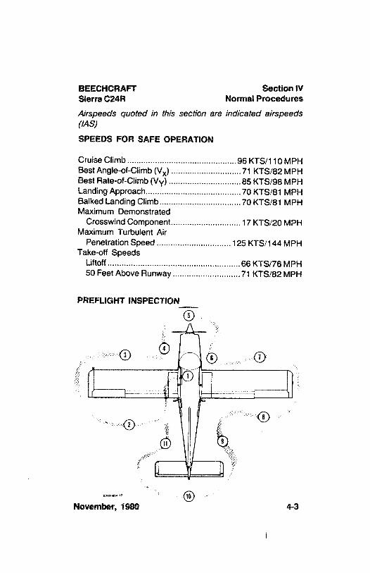
Airspeeds quoted in this section are indicated aírspeeds(IAS)
SPEEDS FOR SAFE OPERATION
Cruise Climb....................... .......................96 KTS/110 MPHBest Angle-of-Climb (Vy) ..............................71 KTS/82 MPHBest Rate-of-Climb (Vy) ...............................85 KTS/98 MPHLanding Approach.........................................70 KTS/81 MPHBalked Landing Climb...................................70 KTS/81 MPHMaximum Demonstrated
Crosswind Component..............................17 KTS/20 MPHMaximum Turbulent Air
Penetration Speed ................................125 KTS/144 MPHTake-off Speeds
Liftoff........................... ..........................66 KTS/76 MPH50 Feet Above Runway .............................71 KTS/82 MPH
PREFLIGHT INSPECTION
November, 1980 4-3
Section IV BEECHCRAFTNormal Procedures Sierra C24R
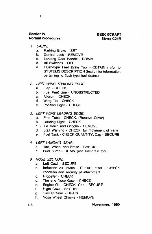
1. CAS/N:a. Parking Brake - SETb. Control Lock - REMOVEc. Landing Gear Handle - DOWNd. All Switches - OFFe. Flush-type Fuel Drain Tool - OBTAIN (refer to
SYSTEMS DESCRIPTION Section for informationpertaining to flush-type fuel drains)
2. LEFT WING TRA/LINGEDGE:a. Flap - CHECKb. Fuel Vent Line - UNOBSTRUCTEDc. Aileron - CHECKd. Wing Tip - CHECKe. Position Light - CHECK
3. LEFT WING LEADINGEDGE:a. Pitot Tube - CHECK, (Remove Cover)b. Landing Light - CHECKc. . Tie Down and Chocks - REMOVEd. Stall Warning - CHECK, for movement of vanee. Fuel Tank - CHECK QUANTITY; Cap - SECURE
4. LEFT LANDING GEAR:a. Tire, Wheel and Brake - CHECKb. Fuel Sump - DRAIN (use fuel-drain tool)
5. NOSE SECTION:a. Left Cowl - SECUREb. Induction Air Intake - CLEAR; Filter - CHECK
condition and security of attachment.c. Propeller - CHECKd. Tire and Nose Gear - CHECKe. Engine Oil - CHECK, Cap - SECUREf. Right Cowl - SECUREg. Fuel Strainer - DRAINh. Nose Wheel Chocks - REMOVE
4-4 November, 1980
BEECHCRAFT Section IVSierra C24R Normal Procedures
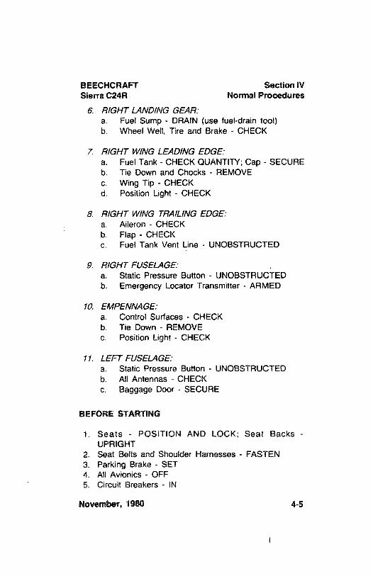
6 R/GHT LAND/NG GEAR:a. Fuel Sump - DRAIN (use fuel-drain tool)b. Wheel Well, Tire and Brake - CHECK
7 R/GHT WING LEADINGEDGE:a. Fuel Tank - CHECK QUANTITY; Cap - SECUREb. Tie Down and Chocks - REMOVEc. Wing Tip - CHECKd. Position Light - CHECK
8 R/GHT W/NG TRA/LING EDGE:a. Aileron - CHECKb. Flap - CHECKc. Fuel Tank Vent Line - UNOBSTRUCTED
9 R/GHT FUSELAGE:a. Static Pressure Button - UNOBSTRUCTEDb. Emergency Locator Transmitter - ARMED
10 EMPENNAGE:a. Control Surfaces - CHECKb. Tie Down - REMOVEc. Position Light - CHECK
i1. LEFT FUSELAGE:a. Static Pressure Button - UNOBSTRUCTEDb. All Antennas - CHECKc. Baggage Door - SECURE
BEFORE STARTING
1. Seats - POSITION AND LOCK; Seat Backs -
UPRIGHT2. Seat Belts and Shoulder Harnesses - FASTEN3. Parking Brake - SET4. All Avionics - OFF5. Circuit Breakers - IN
November, 1980 4-5
Section IV BEECHCRAFTNormal Procedures Sierra C24R
6. Landing Gear Switch Handle - DOWN7. Flaps - UP8. Light Switches - AS REQUIRED9. Electric Trim Switch - OFF
10. Battery Switch - ON11. Alternator Switch - ON (tf external power is used, tum
Alternator Switch - OFF)12. Fuel Selector Valve - ROTATE thru 360°
and checkfor freedom of movement; set on tank more nearly full(feel for detent and check visually)
NOTEOn serials MC-696 and after, or on airplaneswhich have complied with BEECHCRAFT S.I.No. 1095, a fuel selector stop has been addedto the selector valve guard. The fuel selectorstop minimizes the possibility of inadvertentlyturning the fuel selector valve to the OFFdetent position. The stop is a spring whichmust be depressed before the selector valvehandle can be rotated to the OFF position.
WARNING
Do not take off if either fuel quanity gageindicates in yellow arc.
EXTERNAL POWER
The following precautions shall be observed while usingexternal power:
1. The Battery Switch shall be ON and all avionics andelectrical switches OFF. This protects the voltageregulator and associated electrical equipment frompower fluctuations.
4-6 November, 1980
BEECHCRAFT Section IVSierra C24R Normal Procedures
2. The airplane has a negative ground system. Connectthe positive and negative leads of the external powercable to the corresponding positive and negativeterminals of the auxiliarypower source.
3. In order to prevent arcing, no power shalt be suppliedwhile the connection is being made.
STARTING ENGINE USING AUXILIARY POWER UNIT
1. Alternator, Electrical, and Avionics Equipment - OFF2. Auxiliary Power Unit - CONNECT3. Auxiliary Power Unit - SET OUTPUT (*13.75to 14.25
volts for 14-volt system and 27.75 to 28.25 volts for28-volt system)
4. Auxiliary Power Unit - ON5. Engine - START using normal procedures6. Auxiliary Power Unit - OFF (after engine has been
started)7. Auxiliary Power Unit - DISCONNECT8. Alternator Switch - ON
*NOTE- MC-449, MC-452 thru MC-673 are
14-volt systems. MC-674 and after are 28-voltsystems.
ENGINE STARTING
1. Propeller - FULL FORWARD (high rpm)2. Engine Start
CAUTION
Starter cranking period should be limited to amaximum of 30 seconds, with at least 2minutes between cranking periods.
Co/d Start:a. Mixture - FULL RICH
November, 1980 4-7
Section IV BEECHCRAFTNormal Procedures Sierra C24R
b. Throttle - FAST IDLEpositionc. Fuel Boost Pump - ON (Maximum 3 seconds,
then OFF)d. Magneto/Start Switch - START position (release
to BOTH position when engine fires)
Hot Start:a. Mixture - IDLECUT-OFFb. Throttle - FAST IDLEpositionc. Magneto/Start Switch - ENGAGEd. Mixture - ADVANCE MIXTURE SLOWLY until
engine starts firing regularly.
Rooded Engine:a. Mixture - IDLECUT-OFFb. Throttle - FULL OPENc. Magneto/Start Switch - ENGAGEd. Mixture - ADVANCE MIXTURE SLOWLY as
engine starts firing regularly.e. Throttle - RETARD (to fast idle position)
3. External Power (if used) - DISCONNECT4. Altemator Switch - ON5. Oil Pressure - ABOVERED RADIALWITHIN THIRTY
SECONDS6. Warm-up - 1000 to 1200 RPM7. Starter Engaged Warning Light (if installed) - CHECK;
should be illuminated during start, and extinguishedafter start.
CAUTION
If the STARTER ENGAGED Warning Light isinoperative (or not installed), ensure that theammeter indication is less than 25% of fullcharge at 1000 or 1200 rpm within two minuteswith no additional electrical equipment on. Ifnot, turn off the BATTERY & ALT and ALTSwitches and do not take off.
4-8 November, 1980
BEECHCRAFT Section IVSierra C24R Normal Procedures
8. Engine Instruments - CHECK9. Throttle - IDLE
10. Parking Brakes - RELEASE
AFTER STARTING,AND TAXI
1. Brakes - RELEASE AND CHECK2. Avionics Equipment - ON, AS REQUIRED3. Lights - AS REQUIRED
CAUT/ON
Detuning the counterweight system of theengine can occur by rapid throttle operation,high rpm (low pitch) and low manifoldpressure,or propeller feathering. (See latest revision ofLycoming Service Bulletin No. 245.)
BEFORE TAKEOFF
1. Parking Brake - SET2. Seat Belts and Shoulder Harnesses - CHECK3. Avionics - CHECK4. Engine Instruments - CHECK5. Flight Instruments - CHECK and SET6. Starter Engaged Warning Light(if installed) - CHECK
(should not be illuminated). If light is not installed or isinoperative, the ammeter indication should be lessthan 25% of full charge at 1000 to 1200 rpm andshould show some decrease from the initial indication.
7. Throttle - 2000 RPM8. Magnetos - CHECK at 2000 rpm, maximum drop of
100 rpm on each magneto, variance betweenindividual magnetos should not exceed 25 rpm.
November, 1980 4-9
Section IV BEECHCRAFTNormal Procedures Sierra C24R
9. Propeller - EXERCISE to obtain 300 to 400 rpm drop;return to high rpm.
10. Throttle - FAST IDLE11. Stabilator Trim - TAKE-OFF RANGE (within indicator
band)12. Flaps - CHECK and SET
(15°)
13. Controls - CHECK FREE and for proper direction oftravel
14. Mixture - FULL RICH (or as required by field elevation)15. Doors and Window - SECURE16. Parking Brake - RELEASE17. Instruments - CHECK (Make final check of manifold
pressure, fuel flow, and rpm at the start of the take-offrun.)
TAKEOFF
Take-Off...........................................Full Throttle - 2700 RPMCruise Climb.................................... Full Throttle - 2700 RPM
NOTE
Do not take off or land with the Fuel BoostPump ON. The Fuel Boost Pump should beused only for starting and in the event of anemergency.
1. Power - SET take-off power and mixture before brakerelease.
2. Airspeed - ACCELERATE to and maintain take-offspeed.
3. Landing Gear - RETRACT when airplane is positivelyairborne and insufficient runway remains for a landing.
4. Airspeed - ESTABLISH DESIRED CLIMB SPEEDwhen clear of obstacles.
4-10 June, 1984
BEECHCRAFT Section IVSierra C24R Normal Procedures
CLIMB
1. Flaps - UP2. Power - AS REQUIRED3. Mixture - LEAN AS REQUIRED4. Temperature - MONITOR
CRUISEI
1. Power - SET AS DESIRED (Use tables in PerformanceSection)
2. Mixture - LEAN AS REQUIRED
LEANING MIXTURE USING THE EXHAUST GAS ETEMPERATURE INDICATOR (EGT)
For level flight at 75% power or less, the EGT unit should beused in the following manner:
1. Lean the mixture and note the point on the indicator atwhich the temperature peaks and starts to fall.
a. CRUISE (LEAN) MIXTURE - Enrich mixture (pushmixture control forward) until EGT indicator showsa drop of 25°F to 50°F on rich side of peak.
b. BEST POWER MIXTURE - Enrich mixture (pushmixture control forward) until EGT indicator showsa drop of 75°F to 100°F on rich side of peak.
CAUTION
Do not continue to lean mixture beyond thepoint necessary to establish peak temperature.Continuous operation is recommended at 25°F
or below peak EGT only on rich side of peak.
June, 1984 4-11
Section IV BEECHCRAFTNormal Procedures Sierra C24R
2. Changes in altitude and power setting require EGT tobe rechecked and mixture reset.
3. A mixture resulting in an EGT 25°F on the rich side ofpeak should also result in fuel flow and TAS valuesapproximately equal to those presented in the CruisePower Settings tables in the PERFORMANCE Section.If not, the values derived from the Range, Endurance,and Cruise Speeds charts must be revised accordingly.In very cold weather, EGT's 25°F rich of peak may notbe obtainable.
DESCENT
1. Altimeter - SET2. Power - AS REQUIRED(avoid prolonged idle settings
and low cylinder head temperatures)3. Mixture - ENRICH AS REQUIRED
BEFORE LANDING
1. Seat Belts and Shoulder Harnesses - SECURE
NOTE
All reclining seats must be in the uprightposition during landing.
2. Fuel Selector Valve - SELECT TANK MORE NEARLYFULL (feel for detent and check visually).
3. Mixture - FULL RICH (or as required by field elevation)4. Landing Gear - DOWN and CHECK. (Observe
maximum extension speed.)5. Landing and Taxi Lights - AS REQUIRED6. Flaps - DOWN (Observe maximum extension speed)
4-12 June, 1984
BEECHCRAFT Section IVSierra C24R Normal Procedures
WARNING
The distance for a flaps-up landing will begreater than for a flaps-down landing.
7. Airspeed - ESTABLISH LANDING APPROACHSPEED
8. Propeller - FULL FORWARD (High rpm position)
BALKED LANDING
1. Mixture - FULL RICH (or as required by field elevation).2. Propeller - FULL FORWARD (High rpm)3. Power - FULL THROTTLE, 2700 RPM4. Landing Gear - UP5. Airspeed - 70 KTS/81 MPH until clear of obstacles,
then TRIM TO BEST RATE-OF-CLIMB SPEED6. Flaps - UP
AFTER LANDING
1. Landing and Taxi Lights - AS REQUIRED2. Flaps - UP3. Trim Tab - SET TO
0°
SHUTDOWN
1. Parking Brakes - SET a2. Electrical and Avionics Equipment - OFF3. Throttle - CLOSE4. Mixture - IDLE CUT-OFF5. Magneto/Start Switch - OFF, after engine stops6. BATTERY & ALT Switch - OFF7. ALT Switch - OFF8. Control Lock - INSTALL9. Install wheel chocks and release parking brakes if the
airplane is to be left unattended.
June, 1984 4-12A

Section IV BEECHCRAFTNormal Procedures Sierra C24R
INTENTIONALLY LEFT BLANK
4-128 June, 1984
BEECHCRAFT Section IVSierra C24R Normal Procedures
ENVIRONMENTAL SYSTEMS
HEATING AND VENTILATION
Refer to the SYSTEMS DESCRIPTION Section foroperation of heating and ventilation controls.
COLD WEATHER OPERATION
PREFLIGHT INSPECTION
All accumulations of ice, snow and frost must be removedfrom the wings, tail, control surfaces and hinges, propeller,windshield, fuel cell filler caps, crankcase vents, and fuel
June, 1984 4-13
Section IV BEECHCRAFTNormal Procedures Sierra C24R
vents. If such accumulations are not removed completely,the airplane shall not be flown. The deposits willnot blow offin flight. While an adverse weight factor is clearly involved inthe case of heavy deposits, it is less obvious that even slightaccumulations will disturb or completely destroy thedesigned aerodynamic properties of the airfoils.
The normal preflight procedures should then be completed,with particular attention given to check of flight controls forcomplete freedom of movement.
ENGINE
Use engine oil in accordance with Consumable Materials inthe HANDLING, SERVICING AND MAINTENANCE Section
WARNING
Ascertain that magneto switch and batterymaster switchare offbefore moving propeller byhand.
Always pull the propeller through by hand, opposite thedirection of rotation, several times to clear the engine and"limber up" the cold, heavy oil before using the starter. Thiswill also lessen the load on the battery if external power isnot used.
Under very cold conditions, it may be necessary to preheatthe engine prior to a start. Particular attention should begiven to the oil cooler, engine sump and propeller hub toensure proper preheat. A start with congealed oil in thesystem may produce an indication of normal pressureimmediately after the start, but then the oil pressure maydecrease when residual oit in the engine is pumped back
4-14 November, 1980
BEECHCRAFT Section IVSierra C24R Normal Procedures
with the congealed oil in the sump. If an engine heatercapable of heating both the engine sump and cooler is notavailable, the oil should be drained while the engine is hotand stored in a warm area until the next flight.
If there is no oil pressure within the first 30 seconds ofrunning, or if oil pressure drops after a few minutes ofground operation, shut down and check for broken oil lines,oil cooler leaks or the possibility of congealed oil.
NOTE
It is advisable to use external power for startingin cold weather.
During warm-up, monitor engine temperatures closely, sinceit is quite possible to exceed the cylinderhead temperaturelimit in trying to bring up the oil temperature. Exercise thepropeller several times to remove cold oil from the pitchchange mechanism. The propeller should also be cycledoccasionally in flight.
During letdown and landing, give special attention to enginetemperatures, since the engine will have a tendency towardovercooling.
ICING CONDITIONS
Flight in Known Icing Conditions Prohibited.
ENGINE BREAK-IN INFORMATION
See Systems Description section.
Novembern980 4-15
Section IV BEECHCRAFTNormal Procedures Sierra C24R
NOISE CHARACTERISTICS
Approach to and departure from an airport should be madeso as to avoid prolonged flight at low altitude near noise-sensitive areas. Avoidance of noise-sensitive areas, ifpractical, is preferable to overflightat relatively low altitudes.
For VFR operations over outdoor assemblies of persons,recreational and park areas, and other noise-sensitiveareas, pilots should make every effort to fly not less than2000 feet above the surface, weather permitting, eventhough flight at a lower level may be consistent with theprovisions of government regulations.
NOTE
The preceding recommended procedures donot apply where they would conflict with AirTraffic Control clearances or instructions, orwhere, in the pilot's judgement, an altitude ofless than 2000 feet is necessary to adequatelyexercise his duty to see and avoid otherairplanes.
Flyover noise level established in compliance with FAR 36is:
71.7 dB(A)
No determination has been made by the Federal AviationAdministration that the noise level of this airplane is orshould be acceptable or unacceptable for operation at, into,or out of any airport.
4-16 November, 1980
BEECHCRAFTSierra C24R
SECTION V
PERFORMANCE
TABLE OF CONTENTS
SUBJECT PAGE
Introduction to Performance andFlight Planning ......................... ... ......................
5-3Comments Pertinent to the Use of
Performance Graphs.....................................................5-8Airspeed Calibration - Normal System............................ 5-10Airspeed Calibration -Emergency System...................... 5-11Altimeter Correction - Normal System............................. 5-12Altimeter Correction - Emergency System...................... 5-13Fahrenheit to Celsius Temperature Conversion.............. 5-14ISA Conversion......................... . ......................
5-15StallSpeeds - Power Idle..................... .......................
5-16Wind Components ....................... . .......................
5-17Take-Off Distance - Hard Surface................................... 5-18Take-Off Distance - Grass Surface................................. 5-19Normal Climb............................... ......................
5-20Time, Fuel, and Distance to Climb ..................................
5-21Cruise Power Settings
2700 RPM - Full Throttle.............................................. 5-222700 RPM -75% MCP(OrFullThrottle)...................... 5-232500 RPM -75% MCP(OrFull Throttle)...................... 5-242400 RPM - 65% MCP (Or Full Throttle)...................... 5-252400 RPM - 55% MCP ................................................
5-26Cruise Speeds ...................... . .....................
5-27Manifold Pressure vs RPM....................... ......................
5-28Range Profile - 37 Gallons ...................... . ...................
5-29
December, 1982 5-1
Section V BEECHCRAFTPerformance Sierra C24R
SUBÆCT PAGE
Range Profile - 57 Gallons ....................... ......................
5-30Endurance Profile - 37 Gallons .......................................
5-31Endurance Profile - 57 Gallons
.......................................5-32
Landing Distance - Hard Surface ....................................
5-33Landing Distance - Grass Surface ..................................
5-34
5-2 November, 1980
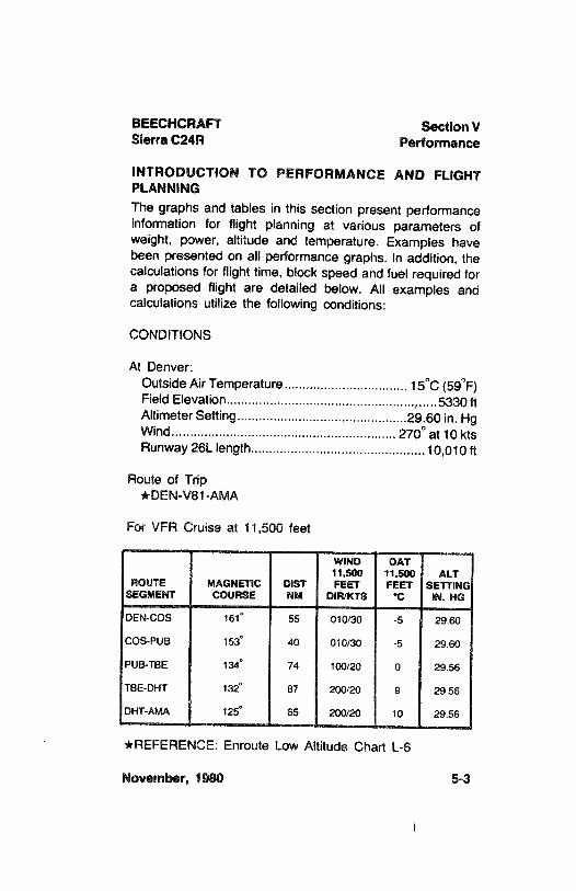
BEECHCRAFT Section VSierra C24R Performance
INTRODUCTION TO PERFORMANCE AND FLIGHTPLANNINGThe graphs and tables in this section present performanceinformation for flight planning at various parameters ofweight, power, altitude and temperature. Examples havebeen presented on all performance graphs. In addition, thecalculations for flight time, block speed and fuel required fora proposed flight are detailed below. AII examples andcalculations utilize the following conditions:
CONDITIONS
At Denver:Outside Air
Temperature..................................15°C (59°F)
Field Elevation....................... . ............................5330 ftAltimeter Setting...............................................29.60 in. HgWind.............................................................. 270° at 10 ktsRunway 26L length................................................10,010 ft
Route of Trip*DEN-V81-AMA
For VFR Cruise at 11,500 feet
WINO OAT11,500 11,500 ALT
ROUTE MAGNETIC DIST FEET FEET SETTINGSEGMENT COURSE NM DIR/KTS °C IN. HG
DEN-COS 161° 55 010/30 -5 29.60
COS-PUB 153° 40 010/30 -5 29.60
PUB-TBE 134° 74 100/20 0 29.56
TBE-DHT 132° 87 200/20 9 29.56
DHT-AMA 125° 65 200/20 10 29.56
*REFERENCE: Enroute Low Altitude Chart L-6
November, 1980 5-3
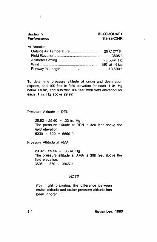
Section V BEECHCRAFTPerformance Sierra C24R
At Amarillo:Outside Air Temperature..................................25°C (77°F)
Field Elevation........................ ........................3605 ftAltimeter Setting...............................................29.56 in. HgWind........................ .......................
180° at 14 ktsRunway 21 Length .......................
........................13,500 ft
To determine pressure altitude at origin and destinationairports, add 100 feet to field elevation for each .1 in. Hgbelow 29.92, and subtract 100 feet from field elevation foreach .1 in. Hg above 29.92.
Pressure Altitude at DEN:
29.92 - 29.60 =.32 in. Hg
The pressure altitude at DEN is 320 feet above thefielp elevation.5330 + 320 = 5650 ft
Pressure Altitude at AMA:
29.92 - 29.56 =.36 in. Hg
The pressure altitude at AMA is 360 feet above thefield elevation.3605 + 360 = 3965 ft
NOTE
For flight planning, the difference betweencruise altitude and cruise pressure altitude hasbeen ignored.
5-4 November, 1980
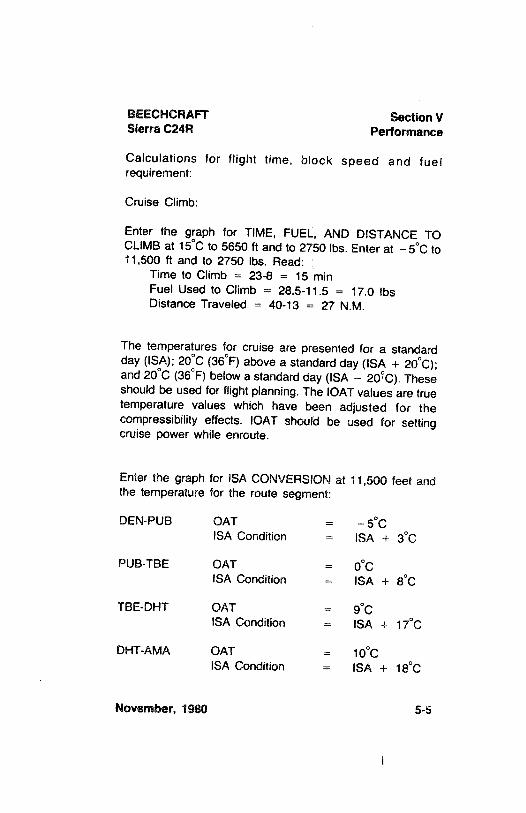
BEECHCRAFT Section VSierra C24R Performance
Calculations for flight time, block speed and fuelrequirement:
Cruise Climb:
Enter the graph for TIME, FUEL, AND DISTANCE TOCLIMB at 15°C to 5650 ft and to 2750 lbs. Enter at -5°C to11,500 ft and to 2750 lbs. Read:
Time to Climb = 23-8 = 15 minFuel Used to Climb = 28.5-11.5 = 17.0 lbsDistance Traveled = 40-13 = 27 N.M.
The temperatures for cruise are presented for a standardday (ISA);
20°C (36°F) above a standard day (ISA + 20°C);
and20°C (36°F)
below a standard day (ISA -
20°C). Theseshould be used for flight planning. The lOAT values are truetemperature values which have been adjusted for thecompressibility effects. IOAT should be used for settingcruise power while enroute.
Enter the graph for ISA CONVERSION at 11,500 feet andthe temperature for the route segment:
DEN-PUB OAT =-5°C
ISA Condition = ISA +3°C
PUB-TBE OAT =0°C
ISA Condition = ISA +8°C
TBE-DHT OAT =9°C
ISA Condition = ISA +17°C
DHT-AMA OAT =10°C
ISA Condition = ISA +18°C
November, 1980 5-5
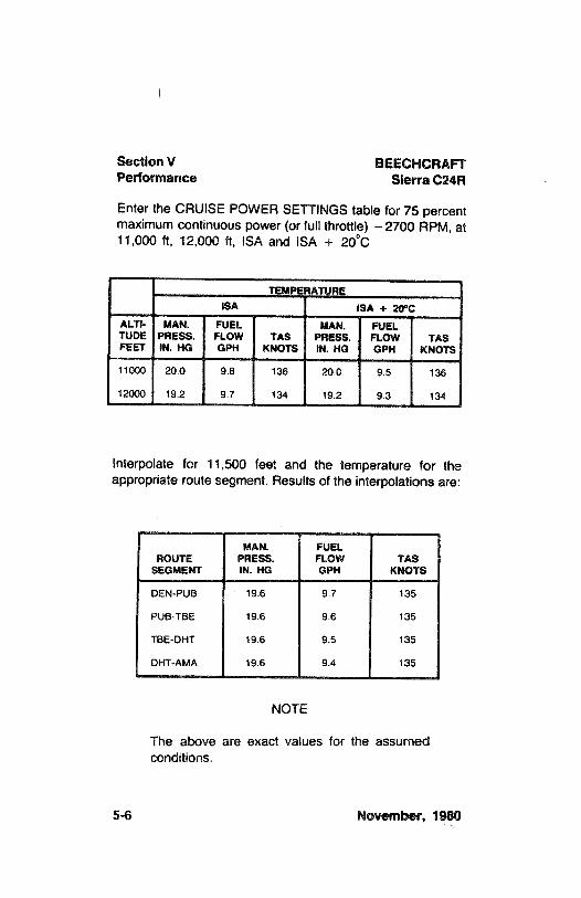
Section V BEECHCRAFTPerformance Sierra C24R
Enter the CRUISE POWER SETTINGStable for 75 percentmaximum continuous power (or full throttle) -2700 RPM, at11,000 ft, 12,000 ft, ISA and ISA +
20°C
TEMPERATUREISA ISA + 20°C
ALTI- MAN. FUEL MAN. FUELTUDE PRESS. FLOW TAS PRESS. FLOW TASFEET IN. HG GPH KNOTS IN. HG GPH KNOTS
11000 20.0 9.8 136 20.0 9.5 136
12000 19.2 9.7 134 19.2 9.3 134
Interpolate for 11,500 feet and the temperature for theappropriate route segment. Results of the interpolations are:
MAN. FUELROUTE PRESS. FLOW TAS
SEGMENT IN. HG GPH KNOTS
DEN-PUB 19.6 9.7 135
PUB-TBE 19.6 9.6 135
TBE-DHT 19.6 9.5 135
DHT-AMA 19.6 9.4 135
NOTE
The above are exact values for the assumedconditions.
5-6 November, 1980
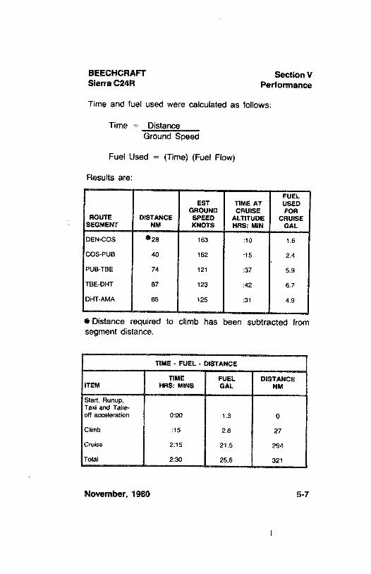
BEECHCRAFT Section VSierra C24R Performance
Time and fuel used were calculated as follows:
Time = DistanceGround Speed
Fuel Used = (Time) (Fuel Flow)
Results are:
FUELEST TIME AT USED
GROUND CRUISE FORROUTE DISTANCE SPEED ALTITUDE CRUISE
SEGMENT NM KNOTS HRS: MIN GAL
DEN-COS 28 163 :10 1.6
COS-PUB 40 162 :15 2.4
PUB-TBE 74 121 :37 5.9
TBE-DHT 87 123 :42 6.7
DHT-AMA 65 125 :31 4.9
* Distance required to climb has been subtracted fromsegment distance.
TIME - FUEL - DISTANCE
TIME FUEL DISTANCEITEM HRS: MINS GAL NM
Start, Runup,Taxi and Take-off acceleration 0:00 1.3 0
Climb :15 2.8 27
Cruise 2:15 21.5 294
Total 2:30 25.6 321
November, 1980 5-7
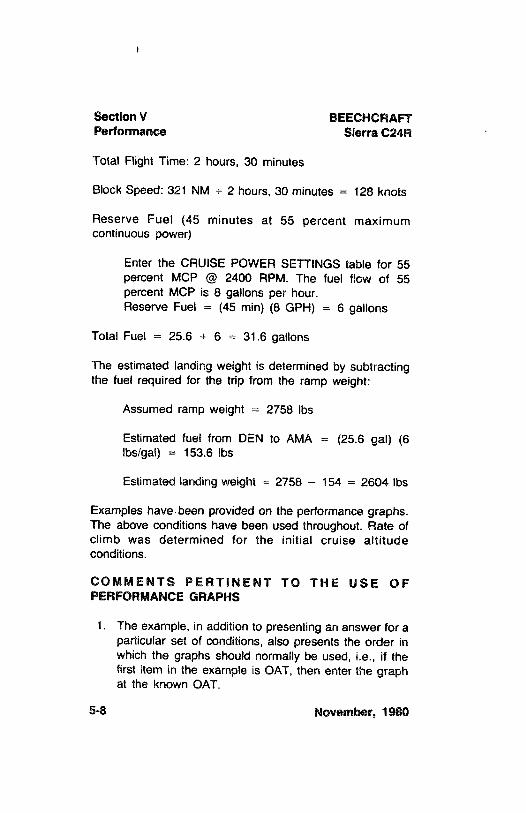
Section V BEECHCRAFTPerformance Sierra C24R
Total Flight Time: 2 hours, 30 minutes
Block Speed: 321 NM ÷ 2 hours, 30 minutes = 128 knots
Reserve Fuel (45 minutes at 55 percent maximumcontinuous power)
Enter the CRUISE POWER SETTINGS table for 55percent MCP @ 2400 RPM. The fuel flow of 55percent MCP is 8 gallons per hour.Reserve Fuel = (45 min) (8 GPH) = 6 gallons
Total Fuel = 25.6 + 6 = 31.6 gallons
The estimated landing weight is determined by subtractingthe fuel required for the trip from the ramp weight:
Assumed ramp weight = 2758 Ibs
Estimated fuel from DEN to AMA = (25.6 gal) (6Ibs/gal) = 153.6 Ibs
Estimated landing weight = 2758 - 154 = 2604 lbs
Examples have.been provided on the performance graphs.The above conditions have been used throughout. Rate ofclimb was determined for the initial cruise altitudeconditions.
COMMENTS PERTINENT TO THE USE OFPERFORMANCE GRAPHS
1. The example, in addition to presenting an answer for aparticular set of conditions, also presents the order inwhich the graphs should normally be used, i.e., if thefirst item in the example is OAT, then enter the graphat the known OAT.
5-8 November, 1980
BEECHCRAFT Section VSierra C24R Performance
2. The reference lines indicate where to begin followingguide lines. Always project to the reference line first,then follow the guide lines to the next known item.
3. Indicated airspeeds (IAS) were obtained by using theAIRSPEED CALIBRATION-NORMALSYSTEM Graph.
4. The associated conditions define the specificconditions from which performance parameters havebeen determined. They are not intended to be used asinstructions; however, performance values determinedfrom charts can only be achieved if the specifiedconditions exist.
5. The full amount of usable fuel is available for allapproved flight conditions.
6. Engine and component cooling has beendemonstrated for temperatures up to 100°F at sea levelwith a 3.67°F per 1000 ft lapse rate. (ISA + 41°F).
November, 1980 5-9
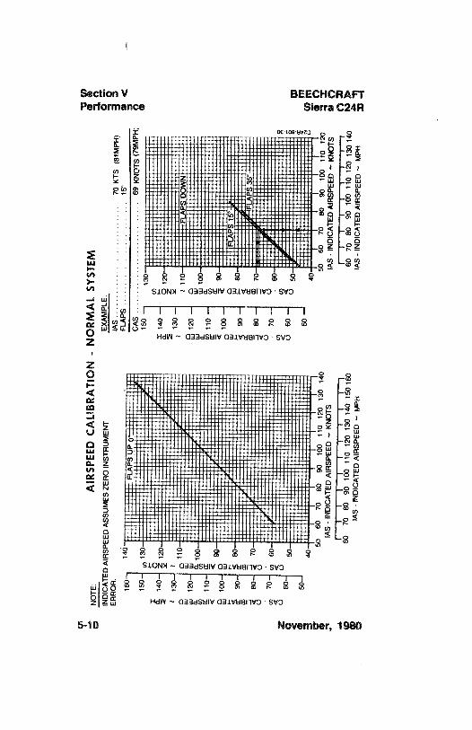
\
Section V BEECHCRAFTPerformance Sierra C24R
00 109 U
© 11111111111
SlONM 03BdSHIV GB1VB811VO - SVOIlttitli
5-10 November, 1980
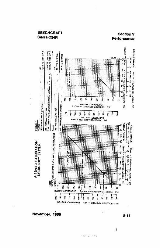
AIR
SPEE
DC
ALI
BR
ATI
ON
-EX
AM
PLE.
ggEM
ERG
ENC
YSY
STEM
FLA
PS...
..U
Pg'
gIA
S-EM
ERG
ENC
YSY
STEM
125
KTS
(144
MPH
)g
geO
IAS-
NO
RM
AL
SYST
EM12
0K
TS(1
38M
PH)
CA
S-(S
EEA
IASP
EED
CA
USA
AT
ON
NO
RM
AL
SYST
EM12
0K
TS(1
38M
PH)
ÛN
OTE
ATE
DA
IRSP
EED
ASS
UM
ESZE
RO
INST
RU
MEN
TER
RO
A.
IAS-
NO
AM
AL
SYST
EM.
80K
TS(9
2M
PH)
1::•:
::::*
::::l;
IAS
EMER
GEN
CY
SYST
EM65
KY
S(9
8M
PH)
it:::
:FLA
PSU
PO
Tip
::40
FLA
PSD
OW
N(3
5}
6070
EG90
100
110
10
130
140
150
160
170
5)60
7080
9310
01
O12
0
IAS
-IN
DI
ATE
DA
IRSP
EED
~K
NO
TSN
OR
MA
LSY
STEM
lAS
-IN
DIC
ATE
DA
IASP
EED
-K
NO
TSN
OA
MA
LSY
STEM
70W
901
110
im1
10
1¾1
170
TW\
m70
80m
im11
012
013
014
0-a
IAS
-IN
DIC
ATE
DA
IRSP
EED
-M
PHN
OA
MA
LSY
STEM
lAS
-IN
DIC
ATE
DA
IRSP
EED
-M
PHN
OR
MA
LSY
STEM
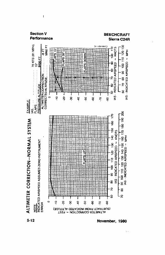
ALT
IMET
ERC
OR
REC
TIO
N--
NO
RM
AL
SYST
EMEX
AM
PLE:
IAS.
......
.....
......
...70
KTS
(81M
PH)
NO
TE:
FLA
PS...
......
....
......
..
15°
NA
TED
AIR
SPEE
DA
SSU
MES
ZER
OIN
STR
UM
ENT
PRFS
AU
RF
ALT
ITI
IDE
..
..
..
6000
FT,
OER
RO
RA
LTIM
ETER
CO
RR
ECTI
ON
..
..
..
..
..
-8
FTC
OR
REC
TED
ALT
ITU
DE.
..
..
..
..
..
.59
92FT
oo
FLA
PS15
°Q
-10
-10
-
-20
-20
-FL
APS
35°
z-3
0-3
0-
-40
-40
-
-50
-50
-FL
APS
DO
WN
-60
-60
-
-70
-70
-
-80
-80
Ii
iW
m60
7080
9010
011
012
013
014
015
016
017
060
6070
8090
100
110
ggIA
S-IN
DIC
ATE
DA
IRSP
EED
~K
NO
TSIA
S-
IND
ICA
TED
AIA
SPEE
D~
KN
OTS
I
7080
9010
011
012
013
014
015
016
017
018
019
020
060
7080
9010
011
012
013
0lA
S-
IND
ICA
TED
AIR
SPEE
D~
MPH
IAS
-IN
DIC
ATE
DA
IRSP
EED
~M
PH
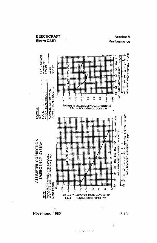
ozA
LTIM
ETER
CO
RR
ECTI
ON
.gM
P
e-
EMER
GEN
CY
SYST
EMIA
S.80
KTS
(92M
PH)
FLA
PSD
OW
N(3
5°)
s"?EM
EEDZAEN
RD
NC
SR
EDLT
FT
oo
1 0-
10
FLA
PSU
P(0
°)-2
0
FLA
PSD
OW
N(3
5)
z-
30- 3
0
m<
-40
O<
-40
- 60
- 60
-90
-90
8070
8090
100
110
120
130
140
150
160
170
5060
7080
9010
011
0
lAS
-IN
DIC
ATE
DA
IRSP
EED
~K
NO
TSlA
S-
IND
ICA
TED
AIR
SPEE
D-
KN
OTS
Ílllll
llllll
flIll
lllll
og70
8090
100
110
120
130
140
150
160
170
180
190
200
6070
8090
100
110
120
130
3g
IAS
-IN
DIC
ATE
DA
IRSP
EED
~M
PHIA
S-
IND
ICA
TED
AIR
SPEE
D~
MPH
g4
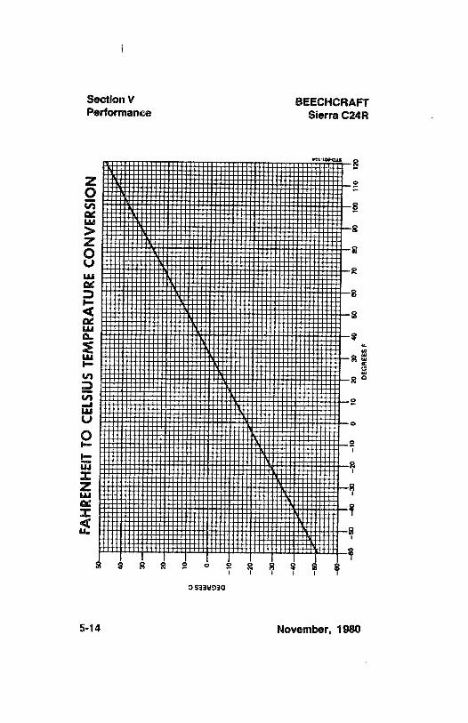
hetionV BEECHCRAFTPerformance Sierra C24R
Lu
zO
ud
I-
zud
5-14 November, 1980
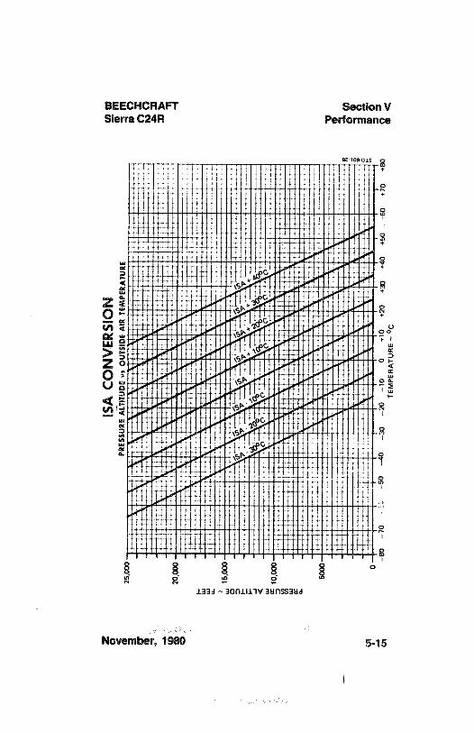
BEECHCRAFT Section VSierra C24R Performance
anosois q
November, 1980 5-15
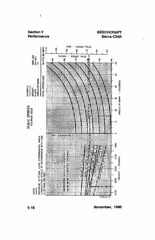
STA
LLSP
EED
SEX
AM
PLE:
POW
ERID
LEW
EIG
HT...
.26
06LB
SN
OTE
FLA
PS.
DN
(35°
)
AN
GLE
OF
BA
NK
15°
MA
XIM
UM
ALT
ITU
DE
LOSS
EXPE
RIE
NC
EDW
HIL
EC
ON
DU
CTI
NG
STA
LLS
INA
CC
OR
DA
NC
EW
ITH
CA
MST
ALL
SPEE
D(tA
S)59
KTS
(68
MPH
)3
120
WA
S30
0FE
ET-1
10
-100
AlI
RTF
2700
2500
2300
2100
1900
010
2030
4050
60
WEI
GH
T~
POU
ND
SA
NG
LEO
FB
AN
K~
DEG
REE
S
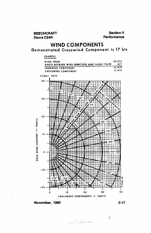
BEECHCRAFT Section VSierra C24R Performance
WIND COMPONENTSDemonstrated Crosswind Component is 17 kts
EXAMPLE:
WIND SPEED 20 KTSANGLE BETWEEN WIND DIRECTION AND FLIGHT PAfH 50°
HEADWIND COMPONENT 13 KTSCROSSWIND COMPONENT 15 KTS
FLIGHT PATH
40
30 -- 30 9 J4
40°
o 50°
20 --
60
70
x 10 --
y° 'o
80°
0 --90°
100°
-10--
110°
--170° 150°
li O* 160° 140° 130 120°
-20
o 10 20 30 40
CROSSWIND COMPONENTS KNOTS
November, 1980 5-17
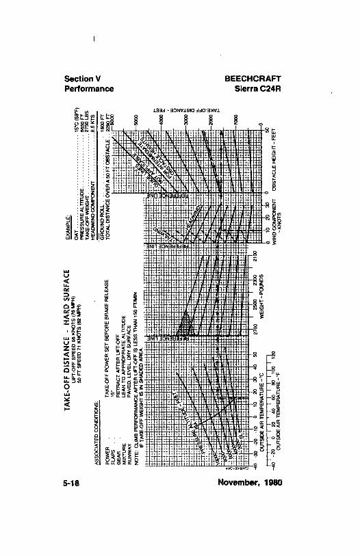
TAK
E-O
FFD
ISTA
NC
E-
HA
RD
SUR
FAC
EEX
AM
PLE:
1m
UFT
-oFF
SPEE
D66
KN
OTS
(76
MPH
)50
FTSP
EED
71K
NO
TS(8
2M
PH)
.1
(W)
TAK
E-O
FFW
EIG
HT
... ,
,,
,.. .
..
....
2750
LBS
ÔA
SSO
CIA
TED
CO
ND
ITIO
NS:
HEA
DW
IND
CO
MPO
NEN
T...
....
..
..
..
.9.
5K
TS
GA
OU
NDR
OLL
..
.16
00FT
UPO
WER
TAK
E-O
FFPO
WER
SET
BEF
OR
EB
RA
KE
REL
EASE
TOTA
LD
ISTA
NC
E OV
ERA
50FT
OB
STA
CLE
2290
FTO
FLA
PS15
'r-
6000
WG
EAR
RET
RA
CT
AFT
ERU
FT-O
FFM
IXTU
RE
LEA
NTO
APP
RO
PRIA
TEA
LTIT
UD
ER
UN
WA
YPA
VED
,LE
VEL
.D
RY
SUR
FAC
EN
OTE
:C
UM
BPE
RFO
RM
AN
CE
AFT
ERU
FT-O
FFIS
LESS
THA
N15
0FT
IMIN
IFTA
KE-
OFF
WEI
GH
TIS
INSH
AD
EDA
REA
-100
0
40-3
0-2
0-1
00
1020
3040
5027
0025
0023
0021
00O
UTS
IDEA
IRTE
MPE
RA
TUR
E~'C
WEI
GH
T~PO
UN
DS
§\\1
1111
111|
¡(10
2030
t0-4
0-2
00
2040
6080
100
120
WIN
DC
OM
PON
ENT
OB
STA
CLE
HEI
GH
T-FE
ETO
UTS
IDE
AIR
TEM
PER
ATU
RE
-*F
-KN
OTS
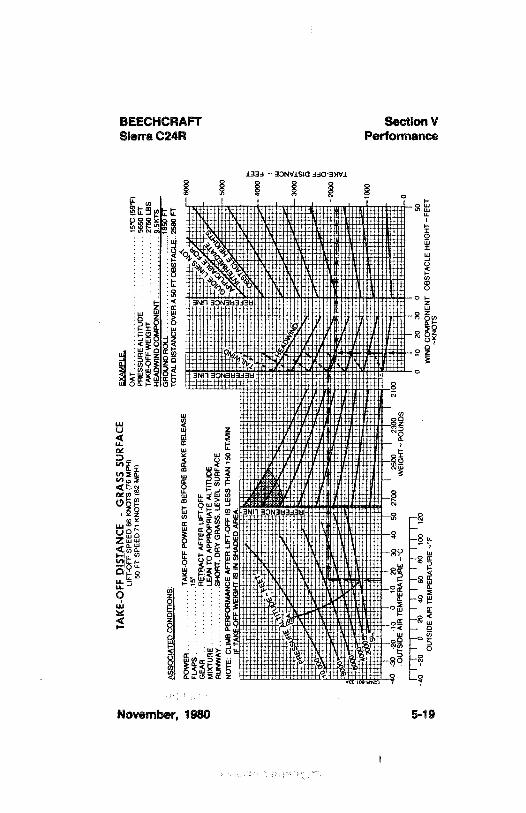
zTA
KE-
OFF
DIS
TAN
CE
-G
RA
SSSU
RFA
CE
pgLI
FTO
FFSP
EED
66K
NO
TS(7
6M
PH)
OA
T.
.....
.... .
..
... .
15°C
(59°
F)g
M50
FTSP
EED
71K
NO
TS(8
2M
PH)
PRES
SUR
EA
LTIT
UD
E56
50FT
gM
TAK
E-O
FFW
EIG
HT
2750
LBS
gÔ
HEA
DW
IND
CO
MPO
NEN
T9.
SKTS
GR
OU
ND
RO
LL.
1860
F^s
soc1
ATE
DC
ON
DIT
ION
S:TO
TAL
DIS
TAN
CEO
VER
A50
FTO
BST
AC
LE..2
500
FT
POW
ER.
..
....
TAK
E-O
FFPO
WER
SET
BEF
OR
EB
RA
KE
REL
EASE
-600
0
FLA
PS.
..
.,..1
5'G
EAR
....
....
.RETR
AC
TA
FTER
LIFT
<)FF
MIX
TUR
E.
..
..
..
.. LE
AN
TOA
PPR
OPR
IATE
ALT
ITU
DE
RU
NW
AY
..
... ..
....
.SH
OR
T,D
RY
GR
ASS
,LE
VEL
SUR
FAC
Ege
NO
TE:
CLI
MB
PER
FOR
MA
NC
EA
FTER
LIFT
4)FF
ISLE
SSTH
AN
150
FT/M
INËi
IFTA
KE-
OFF
WEI
GH
TIS
INSH
AD
EDA
REA
40-3
0-2
olo
o10
2030
4050
2700
2500
2300
2100
OU
TSID
EA
IRTE
MPE
RA
TUR
E-°
CW
EIG
HT
POU
ND
S
-0
20m
im1M
o10
2030
50
OU
TSID
EA
IRTE
MPE
RA
TUR
E~°
FW
IND
CO
NN
ENT
OB
STA
CLE
HEI
GH
T-FE
ET
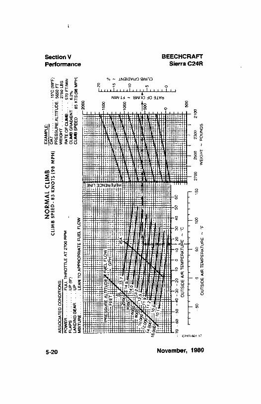
Y'
NO
RM
AL
CLI
MB
EXA
MPL
E:C
LIM
BSP
EED
-85
KN
OTS
(98
MPH
)O
AT
.15°
C(5
9°F)
ASS
OC
IATE
DC
ON
DIT
ION
SPR
ESSU
RE A
LTIT
UD
E.56
50FT
POW
ER.
..
....
.FU
LLTH
RO
TTLE
AT
2700
RPM
WEI
GH
T. .
..
2750
LBS
FLA
PS.
...
....
.U
P(0
°)A
ATE
OF
CLI
MB
570
FT/M
INLA
ND
ING
GEA
RU
PC
LIM
BG
RA
DIE
NT
6.2%
MIX
TUR
ELE
AN
TOA
PPR
OPR
IATE
FUEL
FLO
WC
UM
BSP
EED
,.85
KTS
(98
MPH
)
2000
PRE
SUÀ
EL
UD
FELO
-FE
ETG
PHà°
157
SA10
00
160
6
0-o
- 70
-60
-50
- 40
- 30
- 20
- 10
010
2030
4050
60
oO
UTS
IDEA
IRTE
MPE
RA
TUR
EC
- 50
050
100
150
2700
2500
2300
2100
OU
TSID
EA
IRTE
MPE
RA
TUR
E~
FW
EIG
HT
~PO
UN
DS

zTI
ME,
FUEL
AN
DD
ISTA
NC
ETO
CLI
MB
EXA
MPL
E
ASS
OC
IATE
DC
ON
DIT
ION
S:C
LIM
BSP
EED
-96
KN
OTS
(110
MPH
)5
23PR
OPE
LLEA
SPEE
D27
00R
PMA
IRPO
RT
PRES
SUR
EA
LTIT
UD
E56
50FT
POW
EAFU
LLTH
RO
TTLE
CR
UIS
EA
LTIT
UD
E11
.500
FTFU
ELD
ENSI
TY60
LBSP
ERG
ALL
ON
INIT
IAL
CLI
MB
WEI
GH
T27
50LB
SFL
APS
UP
TIM
ETO
CLI
MB
23-
8=
15M
ING
EAR
UP
FUEL
TOC
LIM
B28
5•
115
=17
LBS
MIX
TUR
ELE
AN
TOA
PPR
OPA
IATE
FUEL
FLO
WO
tSTA
NC
ETO
CLI
MB
40-
1327
NM
3)
IIll
i.
I''l
l'I-
80-
70- 60
- 50
-40
-30
- 20
- 1010
2030
4050
6010
2030
40SO
60
OU
TSID
EA
IRTE
MPE
RA
TUR
E~
°CTI
ME
TOC
LIM
B~
MIN
UTE
S
-100
-50
050
100
FUEL
TC
LIM
B~
POU
ND
SO
UTS
IDE
AIR
TEM
PER
ATU
RE
~°F
Ii
Ii
iI
II
I*
i*
IO
1020
3040
5060
7080
9010
0
DIS
TAN
CE
TOC
LIM
B~
NA
UTI
CA
LM
ILES
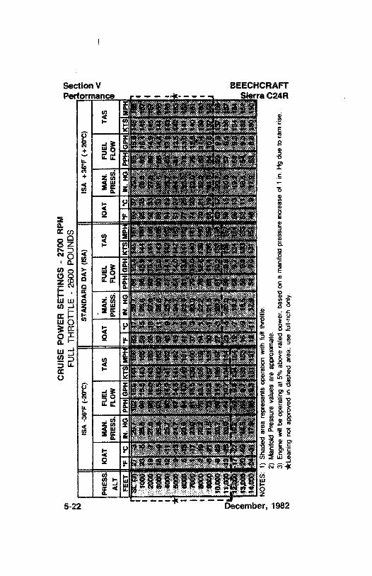
CR
UIS
EPO
WER
SETT
ING
S-
2700
RPM
FULL
THR
OTT
LE-
2600
POU
ND
SIS
A-3
6°F
(-20
°C)
STA
ND
AR
DD
AY
(ISA
)IS
A+3
8°F
(+20
°C)
e
PRES
SIO
AT
MA
N.
FUEL
TAS
10A
TM
AN
.FU
ELTA
SIO
AT
MA
N.
FUEL
TAS
ALT
PRES
S.FL
OW
PRES
S.FL
OW
PRES
S.FL
OW
*F'C
IN.
HG
PPH
GPH
KTS
M'F
*CIN
.H
GPP
HG
PHK
TSM
PH*F
°CIN
.H
GPP
HG
PHK
TSM
PH
tooo
23a
æ.a
sa16
.514
ste
ses
is28
.6es
tok
144
les
esas
as92
184
145
ter
2000
194
27.6
901&
O14
316
5So
1327
.4SS
15.4
144
106
9283
Wh
9914
.914
5lo
t30
0018
428
493
15.5
142
$$$
$211
26.4
W15
,014
316
888
StM
.486
14A
144
105
4000
1241
25.7
8014
.914
118
248
925
287
K4
142
18$
8429
252
143
$$.9
143
185
i50
009
4524
.787
K6
141
182
457
x24
7-8
4
14.0
142
10)
8127
44.7
8810
.514
210
3I
6000
5-1
523
.984
144
140
161
416
&9
8113
.614
110
277
25W
974
13.0
141
182
¡i
7ooo
147
as.o
at13
.5sa
ato
o37
ano
19la
ava
n14
74as
sag
asge
nosa
t,
8000
-249
22.2
7013
.110
015
034
122
.270
19.4
130
100
TO21
22.2
GB
11A
130
100
¡oo
ooo
at21
.sY
a12
2w
tse
aoa
ases
sta
998
mF
**'
A19
IP10
,000
-9-2
320
.70
11,4
100
167
274
20.7
,6)
9)lg
$317
OG
9313
716
811
,000
13•2
620
044
30.7
134
154
4Ñ
J)50
W.8
tw1
5016
200
570,
513
0IS
T0
11
11$
154
194
19.2
609,
713
415
455
1319
260
9ß13
416
4e
is,c
on2o
-asa
.s¢a
eres
iss
te-a
is.s
sesa
naw
psa
11te
.s64
ensa
a15
2em
14.0
0024
•$1
17.9
.A
4.3
13)
151
12-1
117
484
9.0
131
15)
489
17.9
$$8,
813
015
0
NO
TES:
1)Sh
aded
area
repr
esen
tsop
erat
ion
with
full
thro
ttle.
2)M
anifo
ldPr
essu
reva
lues
are
appr
oxim
ate.
o3)
Engi
new
illbe
oper
atin
gat
5%ab
ove
rate
dpo
wer
,ba
sed
ona
man
ifold
pres
sure
incr
ease
of1
in.
Hg
due
tora
mris
eN
ALe
anin
gno
tap
prov
edin
dash
edar
ea;
use
full-
rich
only
,
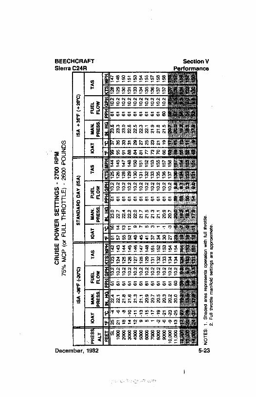
CR
UIS
EPO
WER
SETT
ING
S-
2700
RPM
¢nm
75%
MC
P(o
rFU
LLTH
RO
TTLE
)-
2600
POU
ND
Sm
mO
ISA
-36°
F(-
20°C
)ST
AN
DA
RD
DA
Y(I
SA)
ISA
+36°
F(+
20°C
)M
RES
S10
AT
MA
N.
FUEL
TAS
10A
TM
AN
.FU
ELTA
SIO
AT
MA
N.
FUEL
TAS
ALT
PRES
S.FL
OW
PRES
S.FL
OW
PRES
S.FL
OW
lisili
3EL'
¯iä
lisili
iiiin
iliiis
iii
lii¯i
iii lislii
siiä
iiiiii
si ii
alis
iãiã E
iäis
iii5
-4
22.4
Ό2
TËÎ
6116
23.0
6110
.212
514
499
TiT
ÎÖ"i
TŽŒ
iÎ710
0021
422
.161
10.2
124
143
5714
22.7
6110
.212
614
595
3523
.361
10.2
129
148
2000
18-8
21.8
6110
.212
514
455
1322
.461
10.2
128
147
9133
23.0
6110
.213
015
030
0014
-10
21.6
6110
.212
614
552
1122
.261
10.2
129
148
8831
22.8
6110
.213
115
140
0012
-11
21.3
6110
.212
714
648
922
.061
10.2
130
150
8429
22.5
6110
.213
315
350
009
-13
21.1
6110
.212
814
745
721
.761
10.2
131
151
8127
22.3
6110
.213
415
460
005
-15
20.9
6110
.212
914
841
521
.561
10.2
132
152
7725
22.1
6110
.213
515
570
001
-17
20.7
6110
.213
115
137
321
.361
10.2
133
153
7323
21.9
6110
.213
615
780
00-2
-19
20.5
6110
.213
215
234
121
.161
10.2
135
155
7021
21.8
6110
.213
715
890
004
-21
20.3
6110
.213
315
330
-120
.961
10.2
136
157
6619
21.5
6010
.213
715
810
.000
-9-2
320
261
102
134
154
273
207
6110
213
715
865
1720
1Sg
/11
,000
13-2
520
060
102
134
154
23•5
20.0
599ß
135
157
5915
20.0
MN
OTE
S:1.
Shad
edar
eare
pres
ents
oper
atio
nw
ithfu
llth
rottl
e.2.
Full
thro
ttle
man
ifold
setti
ngs
are
appr
oxim
ate.
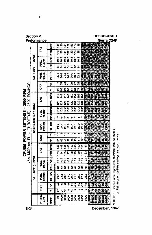
CR
UIS
EPO
WER
SETT
ING
S-
2500
RPM
75%
MC
P(o
rFU
LLTH
RO
TTLE
)-
2600
POU
ND
Se
$IS
A-3
6'F
(-20
°C)
STA
ND
AR
DD
AY
(ISA
)IS
A+3
6°F
(+20
°C)
PRES
S10
AT
MA
N.
FUEL
TAS
10A
TM
AN
.FU
ELTA
S10
AT
MA
N.
FUEL
TAS
ALT
PRES
S.FL
OW
PRES
S.FL
OW
PRES
S.FL
OW
gFE
ET*F
°CIN
.H
GPP
KTS
MPN
*F°C
IN.
HG
PPH
GPH
*F°C
IN.
HG
PPH
GPH
KTS
MPR
SL25
-423
.861
10.2
123
142
6116
24.4
6110
.212
614
599
3725
.161
10.2
129
148
1000
21-6
23.5
6110
.212
414
359
1524
.161
10.2
127
146
9535
24.8
6110
213
015
020
0018
-8
23.3
6110
.212
514
455
1323
.961
10.2
128
147
9133
24.5
6110
.213
115
130
0016
-923
.061
10.2
127
146
5211
23.6
6110
.212
914
883
3124
.261
10.2
132
152
4000
12-1
122
.761
10.2
128
147
489
23.4
6110
.213
015
084
2924
.061
10.2
133
153
5000
9-1
322
.561
10.2
129
148
457
23.1
6110
.213
115
181
2723
.761
10.2
134
154
6000
5-1
522
.361
10.2
130
150
415
22.9
6110
.213
215
277
2523
.561
10.2
135
155
7000
117
221
6110
213
115
137
322
761
102
134
154
7323
232
IT
"1||¶
8000
-219
218
6110
2132
152
341
22.4
6010
0134
154
7021
224
9000
-6-2
121
.600
10.0
132
152
30-1
21.6
599
813
315
366
1921
.6$$
3fŠ
10,0
004
-23
20.8
5092
131
151
27-3
20.8
579
S13
215
263
1720
,9($
1g
11,0
0043
-25
20.1
579.
513
015
023
-5
20.1
569.
313
015
059
1520
,110
0$¾
12,0
0017
-27
19.3
SS92
129
148
19-7
19,3
549.
012
814
7SS
1319
.3$$
127
148
m13
,000
20-2
018
.654
0.0
127
148
16-9
18.6
538.
812
114
652
1448
.6Si
126
144
414
.000
24-3
1
17.9
538.
812
614
512
-11
17.0
528-
712
514
448
9A
7.9
5012
314
22
NO
TES:
1.Sh
aded
area
repr
esen
tsop
erat
ion
with
full
thro
ttle
2.Fu
llth
rottl
em
anifo
ldse
tting
sar
eap
prox
imat
e
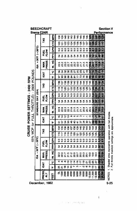
CR
UIS
EPO
WER
SETT
ING
S-24
00R
PM65
%M
CP
(or
FULL
THR
OTT
LE)
-
2600
POU
ND
SIS
A-3
6°F
(-20
°C)
STA
ND
AR
DD
AY
(ISA
)IS
A+3
6*F
(+20
°C)
PRES
SlO
AT
MA
N.
FUEL
TAS
10A
TM
AN
.FU
ELTA
S10
AT
MA
N.
FUEL
TAS
ALT
PRES
S.FL
OW
PRES
S.FL
OW
PRES
S.FL
OW
21
FEET
FIN
,H
GK
TSM
PHIN
.H
GPP
HG
PHH
IN.
HG
SL25
-422
.354
9.0
116
134
6116
22.9
549.
011
813
697
3623
.554
9.0
120
138
1000
21-6
22.0
549.
011
713
557
1422
.654
9.0
119
137
9334
23.2
549.
012
113
920
0018
-821
.754
9.0
118
136
5412
22.3
549.
012
013
890
3223
.054
9.0
122
140
3000
14-1
021
.554
9.0
118
136
5010
22.1
549.
012
113
986
3022
.754
9.0
123
142
4000
10-1
221
.254
9.0
119
137
468
21.8
549.
012
214
084
2922
.454
9.0
124
143
5000
7-1
420
.954
9.0
120
138
436
21.5
549.
012
314
281
2722
.254
9.0
125
144
6000
3-1
620
754
9.0
121
139
415
21.3
549.
012
414
377
2522
.054
9.0
126
145
7000
1-1
720
.554
9.0
122
140
373
21.1
549.
012
514
473
2321
.754
9.0
126
145
8000
-2-1
920
.354
9.0
123
142
341
20.9
549.
012
514
470
2121
.554
9.0
127
146
9000
-6-2
120
.154
9.0
124
143
30-1
20.7
549.
012
614
566
1921
.354
9.0
127
146
10,0
009-
2319
954
9012
514
427
320
554
9012
714
663
1720
.853
0.0
1271
4511
.000
-13
-25
198
5490
125
144
232O
;ttis
8.8
126
14W
5016
20.1
527
128
14&
12,0
0017
-27
193
549
012
514
4la
-7.1
9,8
W$7
125
144
6513
19.3
518.
512
31M
,gou
aoy
tem
«e.
r12
4ta
ais
sW
eaat
xta
s14
2sa
698
,649
et12
0tä
p00
024
417¾
Sie
88
12¾
139
1211
179
498.
212
013
848
917
.948
8.0
117
185
NO
TES:
1.Sh
aded
area
repr
esen
tsop
erat
ion
with
full
thro
ttle.
(n2.
Full
thro
ttle m
anifo
ldse
tting
sar
eap
prox
imat
e.
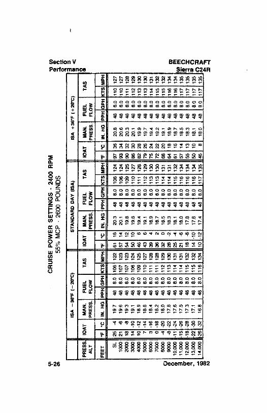
CR
UIS
EPO
WER
SETT
ING
S-
2400
RPM
og55
%M
CP
-
2600
POU
ND
SË
og
ISA
-36°
F(-
20°C
)ST
AN
DA
RD
DA
Y(I
SA)
ISA
+36°
F(+
20°C
)e
<
PRES
S10
AT
MA
N.
FUEL
TAS
10A
TM
AN
.FU
ELTA
S10
AT
MA
N.
FUEL
TAS
ALT
PRES
S.FL
OW
PRES
S.FL
OW
PRES
S.FL
OW
FEET
°F°C
IN.
HG
PPH
GPH
KTS
MPH
*F°C
IN. H
GPP
HG
PHK
TSM
PH*F
°CIN
.HG
PPH
GPH
KTS
MPH
SL25
-419
.748
8.0
106
122
6116
20.3
488.
010
812
497
3620
.848
8.0
110
127
1000
21-6
19.6
488.
010
712
357
1420
.148
8.0
108
124
9334
20.6
488.
011
012
720
0018
-819
.348
8.0
107
123
5412
19.8
488,
010
512
590
3220
.348
8.0
111
128
3000
14-1
019
.148
8.0
108
124
5010
19.6
488.
011
012
786
3020
.148
8.0
112
129
4000
10-1
218
.948
8.0
109
125
468
19.4
488.
011
112
882
2819
.948
8.0
113
130
5000
7-1
418
.648
8.0
110
127
436
19.1
488.
011
212
979
2619
.748
8.0
113
130
6000
3-1
618
.448
8.0
111
128
394
18.9
488.
011
313
075
2419
.448
8.0
114
131
7000
0-1
818
.248
8.0
111
128
362
18.7
488.
011
313
072
2219
.248
8.0
115
132
8000
-4-2
018
.048
8.0
112
129
320
18.5
488.
011
413
168
2019
.148
8.0
115
132
e90
00-8
-22
17.8
488.
011
313
028
-2
18.3
488.
011
413
164
1818
.948
8.0
116
134
gg
10,0
0011
-24
17.6
488.
011
413
125
-418
.148
8.0
115
132
6116
18.7
488.
011
613
4m
911
,000
15-2
617
.548
8.0
114
131
21-6
18.0
488.
011
613
457
1418
.548
8.0
117
135
12,0
0018
-28
17.3
488.
011
513
218
-8
17.8
488.
011
613
455
1318
.348
8.0
117
135
213
,000
22-3
017
.148
8.0
115
132
14-1
017
.648
8.0
116
134
5010
18.1
488.
011
713
514
,000
-26
-32
16.8
488.
011
613
410
-12
174
488.
011
713
546
818
.048
8.0
117
135
y
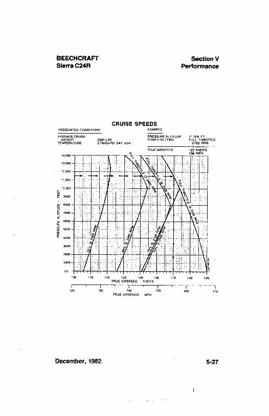
15EECHCRAFT Section VSierra C24R Performance
CRUISE SPEEDSASSOCIATED CONDITIONS EXAMPLE
AVERAGECRUISE PRESSUAE ALTITUDE 11.500 FTWEIGHT 2600 LBS POWERSETTING FULL THROTTLE
TEMPERATURE STANDARD DAY USA) 2700 RPM
TRUEAIRSPEED 135 KNOTS156 MPH
14 000 -
13000-
12 000
11000
10 000 -
105 110 115 1 0 125 130 1 5 140 1-5TRUE A RSPEED KNOTS
120 130 140 150 160 170TRUE AIRSPEED MPH
December,1982 5-27
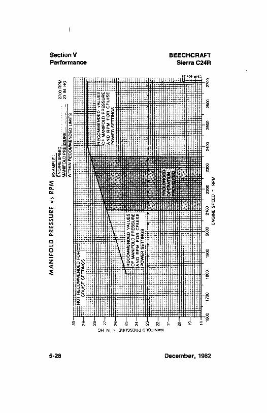
MA
NIF
OLD
PRES
SUR
Evs
RPM
ENG
INES
PEED
LDPR
ESSU
RE
CO
N- o
WIT
HIN
REC
OM
MEN
DED
LIM
ITS
30N
OT
REC
OM
MEN
DED
FOR
29C
RU
ISE
SETT
ING
S
28R
ECO
MM
END
EDV
ALU
ESI
27O
FM
AN
IFO
LDPR
ESSU
RE
AN
DR
PMFO
RC
AU
ISE
POW
ERSE
TTIN
GS
26 25R
ECO
MM
END
EDV
ALU
ESO
FM
AN
IFO
LDPR
ESSU
RE
24A
ND
RPM
FOR
CR
UIS
EPO
WER
SETT
ING
S2 22 20 18
1600
1700
1800
1900
2000
2100
2200
2300
2400
2500
2600
2700
ENG
INE
SPEE
D~
RPM
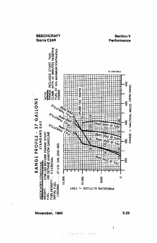
zR
AN
GE
PRO
FILE
-37
GA
LLO
NS
mm
ASS
OC
IATE
DC
ON
DIT
ION
S:ST
AN
DA
RD
DA
Y
gw
EIG
HT
..
..
.27
58LB
SB
EFO
RE
ENG
INE
STA
RT
NO
TE:
gFU
EL-
,.
..
..
100
OC
TAN
EA
VIA
TIO
NG
ASO
LIN
EIN
CLU
DES
STA
RT,
TAX
I,FU
ELD
ENSI
TY..
6.0
LBS/
GA
L4
CÜ
MB
,WIT
H45
MIN
UTE
SRES
ERV
EIN
ITIA
LFU
ELf
FUEL
AT
55%
MA
XIM
UM
CO
NTI
NU
OU
SLO
AD
ING
..
..
.37
U.S
. GA
L(2
22LB
S)PO
WER
15,0
00
LL
CR
UIS
ETA
S~
KN
OTS
w10
,000
--
i--
135
134
125
114
130
130
122
111
IIII
IO
360
380
400
420
440
::I
RA
NG
E~
NA
UTI
CA
LM
ILES
(ZER
OW
IND
)
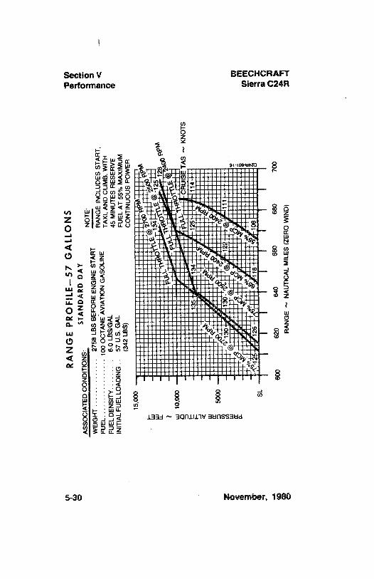
RA
NG
EPR
OFI
LE-5
7G
ALL
ON
Sog
ASS
OC
IATE
DC
ON
DIT
ION
S:ST
AN
DA
RD
DA
YN
OTE
:,
OW
EIG
HT
..
..
..
..
..
..
..
2758
LBS
BEF
OR
EEN
GIN
EST
AR
T--
-
g:
FUEL
..
..
..
..
..
..
..
..
.10
0O
CTA
NE
AV
IATI
ON
GA
SOLI
NE
RA
NG
EIN
CLU
DES
STA
RT,
m<
FUEL
DEN
SITY
...
..
..
..
6.0
LBS/
GA
LTA
XI,
AN
DC
LIM
B,W
ITH
INIT
IALF
UEL
LOA
DIN
G .-
57U
.S. G
AL
45M
INU
TES
RES
ERV
Ee
(342
LBS)
FUEL
AT
55%
MA
XIM
UM
CO
NTI
NU
OU
SPO
WER
w10
,000
OO
CR
UIS
ETA
S~
KN
OTS
135
134
125
114
413
013
0-9
g12
211
1
I\
\|
\\
II
Io
600
620
640
660
680
700
RA
NG
E~
NA
UTI
CA
LM
ILES
(ZER
OW
IND
)
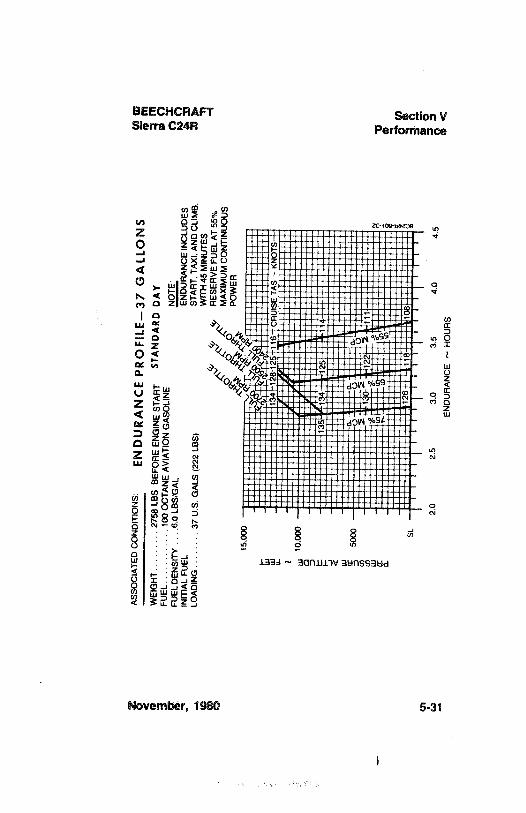
ASS
OC
IATE
DC
ON
DIT
ION
S:EN
DU
RA
NC
EPR
OF
ILE-
37G
ALL
ON
SW
EIG
HT.
.. .
..
..
.27
58LB
SB
EFO
RE
ENG
INE
STA
RT
STA
ND
AR
DD
AY
FUEL
..
..
..
..
..
..
100
OC
TAN
EA
VIA
TIO
NGA
SOLI
NE
NO
TE:
FUEL
DEN
SITY
,.
..6
.0LB
S/G
AL
INIT
IAL
FUEL
END
UR
AN
CE
INC
LUD
ES&
2LO
AD
ING.
..
..
..
.37
U.S
.G
ALS
(222
LBS)
5M
AX
IAC
LIM
B,
4R
ESER
VE
FUEL
AT
55%
MA
XIM
UMC
ON
TIN
UO
US
POW
ER
15.0
00
134
128
2Š11
6C
RU
ISE
TAS
-K
NO
TS-
-
w10
,000
135
134
125
114
SL12
611
810
8
2.0
2.5
3.0
3.5
4O
4.5
END
UR
AN
CE
~H
OU
RS
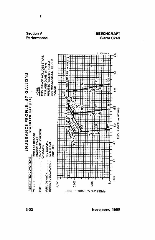
END
UR
AN
CE
PRO
FILE
-57
GA
LLO
NS
ASS
OC
IATE
DC
ON
DIT
ION
S:ST
AN
DA
RD
DA
Y(I
SA)
WEI
GH
T.
..
..
..
..
..
..
.27
58LB
SB
EFO
RE
ENG
INE
STA
RT
NO
TE:
FUEL
100
OC
TAN
EA
VIA
TIO
N.
..
..
..
..
..
..
..
.
GA
SOLI
NE
END
UR
AN
CE
INC
LUD
ESST
AR
T,TA
XI,A
ND
CLI
MB
,WIT
H45
FUEL
DEN
SITY
...
..
..
..
6.0
LBS/
GA
LM
INU
TES R
ESER
VE
FUEL
AT
INIT
IALF
UEL
LOA
DIN
G..
57U
.S.
GA
L55
%M
AX
IMU
M CO
NTI
NU
OU
S(3
42LB
S)PO
WER
1150
,
i16
RU
ISE
TAS
~K
NO
TS
135
125
114
126
118
108
SL3.
54.
04.
55.
05.
56.
06.
57.
0EN
DU
RA
NC
E~
HO
UR
S
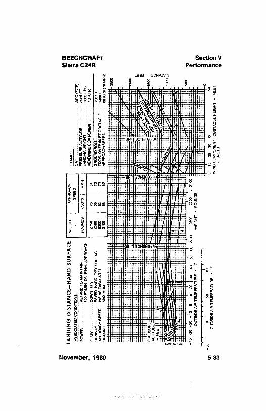
LAN
DIN
GD
ISTA
NC
E-H
AR
DSU
RFA
CE
WEI
GH
TA
PPR
OA
CH
EXA
MPL
E:A
SSO
CIA
TED
CO
ND
ITIO
NS:
~SP
EED
OA
T,. ..
......
....
..
..
25°C
(77°
F)g
ÛPO
WER
..
..
..
..
.RET
AR
DTO
MA
INTA
INPO
UN
DS
KN
OTS
MPH
PRES
SUR
EA
LTIT
UD
E.
..
.39
25FT
800
FTIM
IN.
ON
FIN
ALA
PPR
OA
CH
LAN
DIN
GWEI
GH
T...
.26
06LB
SFL
APS
..
DO
WN
(35°
)27
5070
81H
EAD
WIN
DC
OM
PON
ENT
..,,
12K
TS
RU
NW
AY
PAV
ED.H
AR
D,D
RY
SUR
FAC
E25
0066
75G
RO
UN
DR
OLL
..
.. .
...
-75
0FT
APP
RO
AC
HSP
EED
IAS A
STA
BU
LATE
D23
0062
71TO
TAL
OV
ER50
FTO
BST
AC
LE.
...
1400
FTB
RA
KIN
GM
AX
IMU
M21
0058
67A
PPR
OA
CH
SPEE
D68
KTS
(78
MPH
)
PRES
SUR
E-1
500
ALT
ITU
DE
~FE
ETIS
A
40-3
0-2
0-1
0
010
20I3
040
5060
2700
2500
2300
-21
00O
UTS
IDEA
IRTE
MPE
RA
TUR
E~
°CW
EIG
HT
~PO
UN
DS
OU
TS1D
E AIR
TEM
PER
ATU
RE
~°F
G10
2030
0to
NIN
DC
OM
PON
ENT
OB
STA
CLE
HEI
GH
T~
FEET
~K
NO
TS
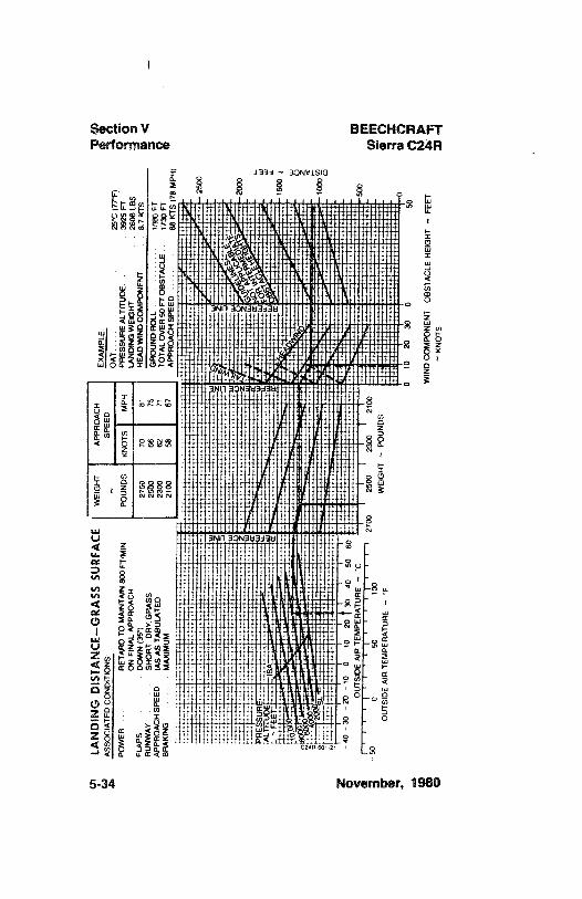
LAN
DIN
GD
ISTA
NC
E-G
RA
SSSU
RFA
CE
WEI
GH
TA
PPR
OA
CH
EXA
MPL
E:A
SSO
CIA
TED
CO
ND
ITIO
NS
SPEE
DO
AT
. ....
25°C
(77°
F)PO
WER
RET
AR
DTO
MA
INTA
IN80
0FT
/MIN
POU
ND
SK
NO
TSM
PHPR
ESSU
RE
ALT
ITU
DE
3925
FT-
gO
NFI
NA
LA
PPR
OA
CH
LAN
DIN
GW
EIG
HT
2606
LBS
3FL
APS
DO
WN
(35
)27
5070
81H
EAD
WIN
DC
OM
PON
ENT
87
KTS
g(
RU
NW
AY
SHO
RT
OR
YG
RA
SS25
0066
75G
RO
UN
DR
OLL
1080
FTA
PPR
OA
CH
SPEE
DIA
SAS
TAB
ULA
TED
2300
6271
TOTA
LO
VER
50FT
OB
STA
CLE
1730
FTB
RA
KIN
GM
AX
IMU
M21
0058
67A
PPR
OA
CH
SPE
D68
KTS
(78
MPH
)
4030
20- 1
00
1020
3040
50O
UTS
IDE
AIR
TEM
PER
ATU
RE~
Ce
i¡
ae
is
|•
·a
i,
,27
oo25
oo23
oo21
oo- 5
0o
solo
oW
EIG
HT
~PO
UN
DS
OU
TSID
EA
IRTE
MPE
RA
TUR
E~
F9
geO
1020
30"
50g
2f4
)>W
IND
CO
MPO
NEN
TO
BST
AC
LEH
EIG
HT
~FE
ET&
3~
KN
OTS
A,
BEECHCRAFTSierra C24R
SECTION VI
WEIGHT AND BALANCE/EQUIPMENT LIST
TABLE OF CONTENTS
SUBJECT PAGE
Introduction To Weight And Balance................................. 6-3
Weighing Instructions ........................ .......................
6-4
Basic Weight And Balance Form....................................... 6-7
Weight And Balance Record .............................................
6-9
Weight And Balance Responsibilities.............................. 6-11
Moment Limits Vs Weight Graph..................................... 6-12
Computing Procedure......................... .......................
6-14
Sample Weight And Balance Loading Form................ 6-15
Weight And Balance Loading Form............................. 6-16
Useful Load Weights And Moments
Occupants.......................... ......................
6-17
Usable Fuel....................... . ....................
6-18
Equipment List. ....... ........ Provided For Each Airplane
November, 1980 6-1
Section VI BEECHCRAFTWt & Bal/Equip List Sierra C24R
INTENTIONALLY LEFT BLANK
6-2 November, 1980
BEECHCRAFT Section VISierra C24R Wt & Bal/Equip Ust
INTRODUCTION TO WEIGHT AND BALANCE
The necessity for proper computation of the airplane'sweight and balance cannot be overemphasized. In the basicdesign, it is planned that under normal loading the weightdistribution of pilot, passengers, baggage, and fuel willbalance the airplane for flight. Since these items are allvariables, it is possible to concentrate weight in such a wayas to make the airplane unsafe for flight. The factors whichmust be considered in the weight and balance of theairplane are the installation of equipment after the airplanehas been weighed, trapped or unusable fuel, engine oil,usable fuel, pilot and passenger weights, and baggage orcargo.
In order to simplify the computation of the weight andbalance, Beech Aircraft Corporation has devised a formcalled Basic Empty Weight and Balance. When the airplaneis delivered from the factory it will first be weighed and thedata recorded on this form. Provision has been made on theform for listing additions of items to be installed before thedelivery or subtractions of items to be removed beforedelivery from the "as weighed" condition. This thenrepresents the empty weight of the airplane.
When the airplane is first fueled, a certain amount of fuel istrapped in the fuel lines and cells which cannot be drained.Also, in some regimes of flight there are certain amounts offuel that cannot be used. The combination of these fuelamounts is classified as unusable fuel. Also, it has beenfound that all operators bring the oil level near full beforeeach flight. Thus, these items are computed along with theempty weight, giving a Basic Empty Weight as a startingpoint to the pilot for each flight computation.
Once the Basic Empty Weight for a given airplane has beenestablished, the pilot is then only concerned with the
November, 1980 6-3
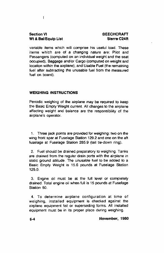
Section VI BEECHCRAFTWt & Bal/Equip List Sierra C24R
variable items which will comprise his useful load. Theseitems which are of a changing nature are: Pilot andPassengers (computed on an individual weight and the seatoccupied), Baggage and/or Cargo (computed on weight andlocation within the airplane), and Usable Fuel (the remainingfuel after subtracting the unusable fuel from the measuredfuel on board).
WEIGHING INSTRUCTIONS
Periodic weighing of the airplane may be required to keepthe Basic Empty Weight current. All changes to the airplaneaffecting weight and balance are the responsibility of theairplane's operator.
1. Three jack points are provided for weighing: two on thewing front spar at Fuselage Station 129.2 and one on the aftfuselage at Fuselage Station 285.9 (tail tie-down ring).
2. Fuel should be drained preparatory to weighing. Tanksare drained from the regular drain ports with the airplane instatic ground attitude. The unusable fuel to be added to aBasic Empty Weight is 15.6 pounds at Fuselage Station125.0.
3. Engine oil must be at the full level or completelydrained. Total engine oil when full is 15 pounds at FuselageStation 50.
4. To determine airplane configuration at time ofweighing, installed equipment is checked against theairplane equipment list or superseding forms. AII installedequipment must be in its proper place during weighing.
6-4 November, 1980
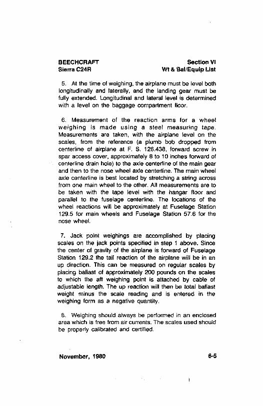
BEECHCRAFT Section VISierra C24R Wt & Bal/Equip List
5. At the time of weighing, the airplane must be level bothlongitudinally and laterally, and the landing gear must befully extended. Longitudinal and lateral level is determinedwith a level on the baggage compartment floor.
6. Measurement of the reaction arms for a wheelweighing is made using a steel measuring tape.Measurements are taken, with the airplane level on thescales, from the reference (a plumb bob dropped fromcenterline of airplane at F. S. 126.438, forward screw inspar access cover, approximately 8 to 10 inches forward ofcenterline drain hole) to the axle centerline of the main gearand then to the nose wheel axle centerîine. The main wheelaxle centerline is best located by stretching a string acrossfrom one main wheel to the other. All measurements are tobe taken with the tape level with the hangar floor andparallel to the fuselage centerline. The locations of thewheel reactions will be approximately at Fuselage Station129.5 for main wheels and Fuselage Station 57.6 for thenose wheel.
7. Jack point weighings are accomplished by placingscales on the jack points specified in step 1 above. Sincethe center of gravity of the airplane is forward of FuselageStation 129.2 the tail reaction of the airplane will be in anup direction. This can be measured on regular scales byplacing ballast of approximately200 pounds on the scalesto which the aft weighing point is attached by cable ofadjustable length. The up reaction will then be total ballastweight minus the scale reading and is entered in theweighing form as a negative quantity.
8. Weighing should always be performed in an enclosedarea which is free from air currents. The scales used shouldbe properly calibrated and certified.
November, 1980 6-5
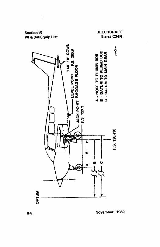
DA
TUM
i
.TA
ILTI
ED
OW
NLE
VEL
POIN
TF.
S.28
5.9
JAC
KPO
INT
BA
GG
AG
EFL
OO
RF.
S.12
9.2
A
Bz
A-
NO
SETO
PLU
MB
BO
BC
B-
DA
TUM
TOPL
UM
BB
OB
mC
-D
ATU
MTO
MA
ING
EAR
iiE
F.S.
126.
438
24,,,
,o
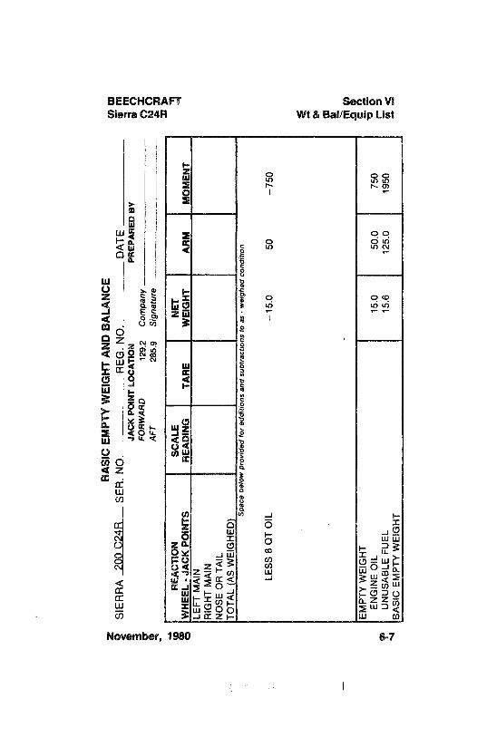
zB
ASI
CEM
PTY
WEI
GH
TA
ND
BA
LAN
CE
SIER
RA
200
C24
RSE
R.
NO
.R
EG.
NO
.D
ATE
JAC
KPO
INT
LOC
ATI
ON
PREP
AR
EDB
YFO
RW
AR
D12
9.2
Com
pany
AFT
285.
9Si
gnat
ure
oR
EAC
TIO
NSC
ALE
NET
WH
EEL
-JA
CK
POIN
TSR
EAD
ING
TAR
EW
EIG
HT
AR
MM
OM
ENT
LEFT
MA
INR
IGH
TM
AIN
NO
SEO
RTA
ILTO
TAL
(AS
WEI
GH
ED) Sp
ace
belo
wpr
ovid
edfo
rad
ditio
nsan
dsu
btra
ctio
nsto
as-
wei
ghed
cond
ition
LESS
8Q
TO
IL-1
5.0
50-7
50
EMPT
YW
EIG
HT
E.A
ENG
INE
OIL
15.0
50.0
750
UN
USA
BLE
FUEL
15.6
125.
019
50B
ASI
CEM
PTY
WEI
GH
T
Section VI BEECHCRAFTWt & Bal/Equip List Sierra C24R
NOTE
Each new airplane is delivered with a completedsample loading, basic empty weight and centerof gravity, and equipment list, all pertinent tothat specific airplane. It is the owner'sresponsibility to ensure that changes inequipment are reflected in a new weight andbalance and in an addendum to the equipmentlist. There are many ways of doing this; it issuggested that a running tally of equipmentchanges and their effect on basic empty weightand CG is a suitable means for meeting bothrequirements.
The current equipment list and basic emptyweight and CG information must be retainedwith the airplane when it changes ownership.Beech Aircraft Corporation cannot maintain thisinformation; the current status is known only tothe owner. If these papers become lost, theFAA will require that the airplane be re-weighedto establish the basic empty weight and CG andthat an inventory of installed equipment beconducted to create a new equipment list.
It is recommended that duplicate copies of theBasic Empty Weight and Balance sheet and theEquipment List be made and kept in analternate location in the event the originalhandbook is misplaced.
6-8 November, 1980
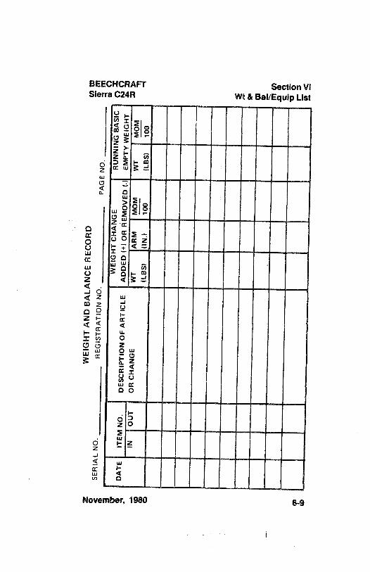
WEI
GH
TA
ND
BA
LAN
CE
REC
OR
Dm
mSE
RIA
LN
O.
REG
ISTR
ATI
ON
NO
.PA
GE
NO
.
WEI
GH
TC
HA
NG
ER
UN
NIN
GB
ASI
CD
ATE
ITEM
NO
.D
ESC
RIP
TIO
NO
FA
RTI
CLE
AD
DED
(+} O
RR
EMO
VED
(-)
EMPT
YW
EIG
HT
A
INO
UT
OR
CH
AN
GE
WT
AR
MM
OM
WT
MO
M(L
BS)
(IN
.)10
0(L
BS)
100
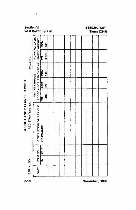
WEI
GH
TA
ND
BA
LAN
CE
REC
OR
Dgg
oSE
RIA
LN
O.
REG
ISTR
ATI
ON
NO
.PA
GE
NO
.ge
yso
WEI
GH
TC
HA
NG
ER
UN
NIN
GB
ASI
Ce
DA
TEIT
EMN
O.
DES
CR
IPTI
ON
OF
AR
TIC
LEA
DD
ED(+
) OR
RM
OV
ED(-
)EM
PTY
WEI
GH
T
INO
UT
OR
CH
AN
GE
WT
AR
MM
OM
WT
MO
Me
(LB
S)(I
N.)
100
(LB
S)10
0r-
BEECHCRAFT Section VISierra C24R Wt & Bal/Equip List
WEIGHT AND BALANCE RESPONSIBILITIES
The Basic Empty Weight and Moment of the airplane atthe time of delivery are shown on the Aircraft Basic EmptyWeight and Balance form. Useful load items which may beloaded into the airplane are shown on the Useful LoadWeights and Moments tables. The minimum and maximummoments are shown on the Moment Limits vs Weight tableand can also be plotted on the Moment Limits vs Weightgraph as visual indication that the limit is within theoperational envelope. These moments correspond to theforward and aft center-of-gravityflight limits for a particularweight. The airplane must be loaded in such a manner tokeep the center of gravity within these limits.
November, 1980 6-11
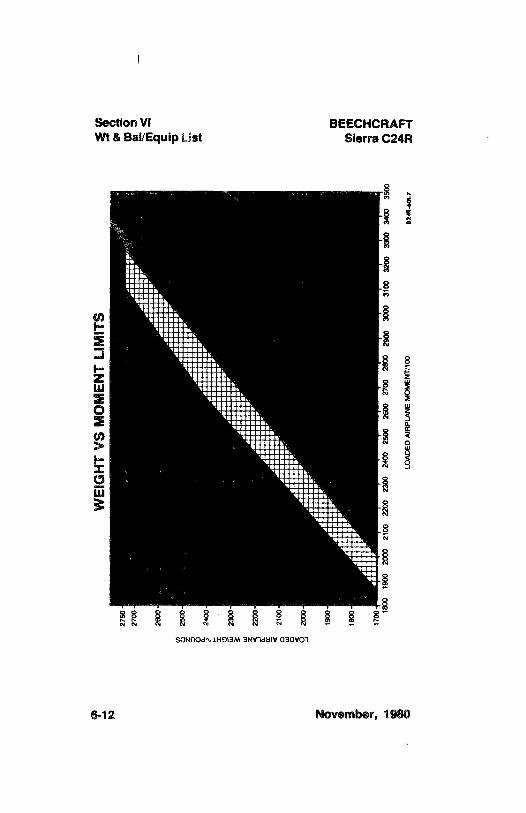
Section VI BEECHCRAFTWt & Bal/Equip List Sierra C24R
- i -
I& 8
!!!!h'Mii!!
o su::::t- NiillNiiiiik
'tisiina alii 'Nil!!LII: ':!!!!i §
1----Ra
maggma
! e i i * I ! ! Ice tu N
SGNAOdo1HOI3M 3NY1dtily 030VO1
6-12 November, 1980
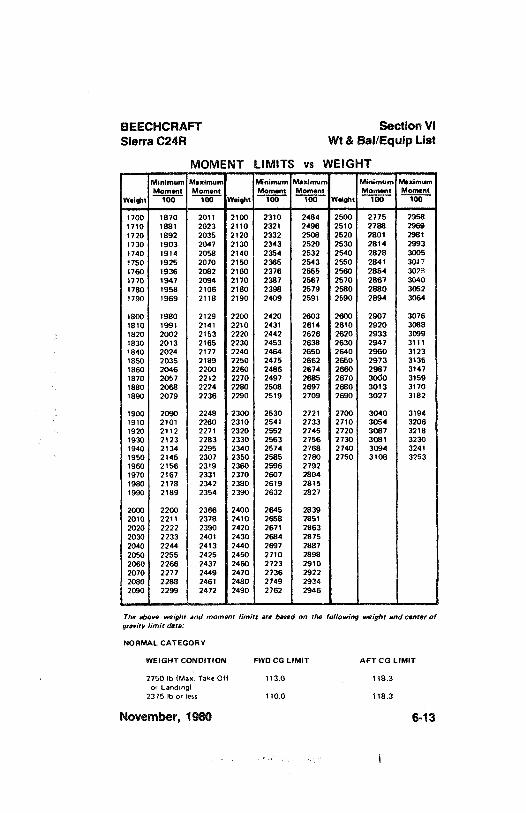
BEECHCRAFT Section VISierra C24R Wt & Bal/Equip List
MOMFNT LIMITA vs WEIG ATMinimum Maximum Minimum Maximum Minimum MaximumMoment Moment Moment Moment Moment Moment
Weight 100 100 Weight 100 100 Weight 100 100mimmism mummmmam -mmmmmm mmmmm -
1700 1870 2011 2100 2310 2484 2500 2775 29581710 1881 2023 2110 2321 2496 2510 2788 29691720 1892 2035 2120 2332 2508 2520 2801 29811730 1903 2047 2130 2343 2520 2530 2814 29931740 1914 2058 2140 2354 2532 2540 2828 30051750 1925 2070 2150 2365 2543 2650 2841 30171760 1936 2082 2160 2376 2565 2660 2854 30281770 1947 2094 2170 2387 2567 2570 2867 30401780 1958 2106 2180 2398 2579 2580 2880 30521790 1969 2118 2190 2409 2591 2590 2894 3064
1800 1980 2129 2200 2420 2603 2600 2907 30761810 1991 2141 2210 2431 2614 2610 2920 30881820 2002 2153 2220 2442 2626 2620 2933 30991830 2013 2165 2230 2453 2638 2630 2947 31111840 2024 2177 2240 2464 2650 2640 2960 31231850 2035 2189 2250 2475 2662 2650 2973 31351860 2046 2200 2260 2486 2674 2660 2987 31471870 2057 2212 2270 2497 2685 2670 3000 31591880 2068 2224 2280 2508 2697 2680 3013 31701890 2079 2236 2290 2519 2709 2690 3027 3182
1900 2090 2248 2300 2530 2721 2700 3040 31941910 2101 2260 2310 2541 2733 2710 3054 32061920 2112 2271 2320 2552 2745 2720 3067 32181930 2123 2283 2330 2663 2756 2730 3081 32301940 2134 2295 2340 2574 2768 2740 3094 32411950 2145 2307 2350 2585 2780 2750 3108 32531960 2156 2319 2360 2596 27921970 2167 2331 2370 2607 28041980 2178 2342 2380 2619 28151990 2189 2354 2390 2632 2827
2000 2200 2366 2400 2645 28392010 2211 2378 2410 2658 28512020 2222 2390 2420 2671 28632030 2233 2401 2430 2684 28752040 2244 2413 2440 2697 28872050 2255 2425 2450 2710 28982060 2266 2437 2460 2723 29102070 2277 2449 2470 2736 29222080 2288 2461 2480 2749 29342090 2299 2472 2490 2762 2946
The above weight and moment limits are based on the following neight and center ofgravity limit data:
NORMAL CATEGORY
WEIGHT CONDITION FWD CG LIMIT AFT CG LIMIT
2750 lb (Max. Take-Off 113.0 118.3or Landing)
2375 lb or less 110.0 118.3
November, 1980 6-13
Section VI BEECHCRAFTWt & Bal/Equip List Sierra C24R
COMPUTING PROCEDURE
1. Record the Basic Empty Weight and Moment from theBasic Empty Weight and Balance form (or from the latestsuperseding form) under the Basic Empty Condition block.The moment must be divided by 100 to correspond toUseful Load Weights and Moments tables.
2. Record the weight and corresponding moment from theappropriate table of each of the useful load items (exceptfuel) to be carried in the airplane.
3. Total the weight column and moment column. TheSUB-TOTALS are the ZERO FUEL CONDITION.
4. Determine the weight and corresponding moment forthe fuel loading to be used. This fuel loading includes fuelfor the flight, plus that required for start, taxi, and takeoff.Add the Fuel Loading Condition to Zero Fuel Condition toobtain the SUB-TOTAL Ramp Condition.
5. Subtract the fuel to be used for start, taxi, and takeoffto arrive at the SUB-TOTAL Take-off Condition.
6. Subtract the weight and moment of fuel to be usedfrom the take-off weight and moment. The SUB-TOTALCondition of No. 3 and No. 5, as well as the landingcondition moment, must be within the minimum andmaximum moments shown on the Moment Limits vs Weightgraph for that weight. If the total moment is less than theminimum moment allowed, useful load items must beshifted aft, or forward load items reduced. If the totalmoment is greater than the maximum moment allowed,useful load items must be shifted forward, or aft load itemsreduced. If the quantity or location of load items is changed,the calculations must be revised and the momentsrechecked.
6-14 November, 1980
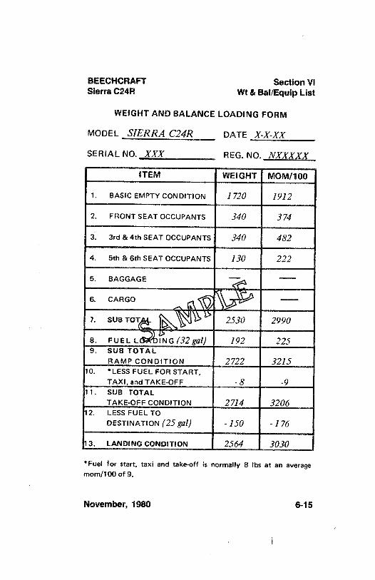
BEECHCRAFT Section VISierra C24R Wt & Bal/Equip List
WEIGHT AND BALANCE LOADING FORM
MODEL SIERRA C24R DATE X-X-XX
SER lAL NO. XXX REG. NO. NXXXXX
ITEM WEIGHT MOM/100
1. BASIC EMPTY CONDITION 1720 1912
2. FRONT SEAT OCCUPANTS 340 374
3. 3rd & 4th SEAT OCCUPANTS 340 482
4. 5th & 6th SEAT OCCUPANTS 130 222
5. BAGGAGE
6. CARGO
7. SUB TOT 2530 2990
8. FUELL I NG (32 gal) 192 2259. SUS TOTAL
RAMP CONDITION 2722 321510. *LESS FUEL FOR START,
TAXI,andTAKE-OFF -8 -9
11. SUB TOTALTAKE-OFF CONDITION 2714 3206
12. LESS FUEL TODESTINATION (25gal) -150 -176
13. LANDING CONDITION 2564 3030
*Fuel for start, taxi and take-off is normally 8 lbs at an averagemom/100 of 9.
November, 1980 6-15

BEECHCRAFTSierra C24R
SECTION VII
SYSTEMS DESCRIPTION
TABLE OF CONTENTS
SUBJECT PAGE
Airframe......................... .
......................7-5
Seating Arrangements ....................... ........................
7-5
Flight ControlsControl Surfaces ....................... . ........................,........
7-5Control Column .......................... . ..........................
7-5Rudder Pedals ........................ ........................
7-6
Stabilator Trim SystemManual Trim......................... ......................
7-6Electric Trim......................... ........................
7-6Instrument Panel......................... ...... .............................
7-6Illustration (MC-449,MC-452 thru MC-536,
except MC-533)........................................................7-7
Illustration (MC-S33, MC-537through MC-570)............7-8Illustration (MC-571and after)....................................... 7-9Switches.......................... ....... .........................
7-10Circuit Breakers......................... ........................
7-10Flight Instruments ......................... . .........................
7-10Ground Control....................... .. ........................
7-11Wing Flaps
Manual ....................... . .........................
7-11Electric............................ ........................
7-11
Effect of Flaps on FlightTakeoff ......................... .........................
7-12Landing Gear.......................... ........................7-12
Control Switch ........................... .........................7-13
Position Indicators......................... .........................
7-13
December, 1982 7-1
Section VII BEECHCRAFTSystems Description Sierra C24R
SUBJECT PAGE
Time Delay Relay (MC-674àndafter)......................... 7-13Safety Retraction Switch .............................................
7-13Warning Horn......................... ........................
7-14CircuitBreaker ........................ ......................
7-14Emergency Extension ......................... .......................
7-14Brakes...................................... ..................................
7-15Landing Gear Safety Extension System...................... 7-15
Baggage Compartment...................................................7-16Seats, Seat Belts, and Shoulder Harnesses
Seat Adjustment........................ .......................
7-17Seat Belts...................... . ......................
7-17Shoulder Harnesses....................... .......................
7-17Doors and Exits
Forward Cabin Doors ....................... .......................
7-18Aft UtilityDoor ......................... ........................
7-19Emergency Exits ......................... . ......................
7-19Control Locks........................ .......................
7-19Engine .................... . . ......................
7-20Engine Controls......................... . ......................
7-20Engine Instruments ........................ ............................
7-20Manifold Pressure and Fuel Flow Indicator.............. 7-20
Illustration ............................................................
7-21Exhaust Gas Temperature Indicator (EGT) .............
7-22Engine Break-in Information........................................ 7-22Cowling...................... . ....................
7-22Lubrication System....................... . . ....................
7-23Induction System Icing ....................... . ......................
7-23Starter ......................... .. .....................
7-23Propeller ........................ ......................
7-24Fuel System......................... ......................
7-24Fuel Tanks ...................... . . ......................
7-24Illustration........................ .....................
7-25Fuel Quantity indicators ..................... .......................
7-25Fuel Drains...................... .....................
7-25Fuel Boost Pump...................... . . ....................
7-27
7-2 November, 1980
BEECHCRAFT Section VIISierra C24R Systems Description
SUBJECT PAGE
Fuel Tank Selection.................... .. .................
7-27Fuel Required For Flight..................... ...................
7-27Electrical System................... . ..................
7-28Battery.................... ...................
7-28Alternator ........................... .....................
7-29External Power Receptacle..................... ...................
7-30
Lighting SystemsInterior Lighting ................... . ...................
7-31Exterior Lighting ................... ..................
7-31Environmental Systems
Illustration...................... ..................... ..................7-32
Cabin Heating .................. ..................... ..................
7-33
Ventilation ...................... . . ...................7-33
.Exhaust Vent.................... ..................
7-34
Pitot and Static SystemsPitot System..................... . ..................
7-34
Pitot Heat.................... ...................
7-34
Normal Static Air System..................... ....................
7-34
Emergency Static Air System...................................... 7-35
Vacuum System..................... ....................
7-35
StallWarning System................... . ................7-35
December, 1982 7-3
Section VII BEECHCRAFTSystems Description Sierra C24R
INTENTIONALLY LEFT BLANK
7-4 November, 1980
BEECHCRAFT Section VIISierra C24R Systems Description
AIRFRAME
The Sierra C24R is a 4-place airplane with an optionalbench-type children's seat in the area otherwise used forbaggage. It is an all-metal, single-engine airplane withretractable tricyclelanding gear. It utilizesconventional flightcontrol surfaces except for a stabilator for the horizontalempennage surface.
SEATING ARRANGEMENTS
In the standard configuration two adjustable seats and onefixed-bench seat are installed. Optional split 3rd and 4thseats and a fixed-bench children's seat are available. Toadjust either of the front seats, pull the release knob belowthe left forward seat corner (pull to the right, then up) andslide the seat forward or aft, as desired. Make certain theseat is locked securely in place after adjustment. The backsof all individual seats can be placed in any of threepositions. Outboard armrests for the front seats areattached to the cabin doors.
FLIGHT CONTROLS
CONTROL SURFACES
The control surfaces are operated with conventional cablesystems terminating in bell cranks.
CONTROL COLUMN
A single control column/wheel is installed as standardequipment on the left side. The optional controlcolumn/wheel may be installed on the right side. These areprovided for stabilator and aileron control.
November, 1980 7-5
Section VII BEECHCRAFTSystems Description Sierra C24R
RUDDER PEDALS
The standard installation provides pedals for rudder controlon the left side only. The optional installation provides a setof rudder pedals on each side.
STABILATOR TRIM SYSTEM
MANUAL TR/M
The manual stabilator trim is actuated by a handwheellocated between the front seats. A stabilator tab positionindicator is located adjacent to the trim control handwheel.Forward movement of the wheel trims the airplane's nosedown, aft movement of the wheel trims the airplane's noseup.
ELECTR/C TR/M
The optional electric stabilator trim system controls includethe ON-OFF circuit-breaker type switch located on theinstrument panel, and a thumb switch on the control wheel.The ON-OFF switch must be in the ON position to operatethe system. The thumb switch must be depressed andmoved forward for nose down, aft for nose up, and whenreleased returned to the center OFF position. When thesystem is not being electrically actuated, the manual trimcontrol wheel may be used.
INSTRUMENT PANEL
The standard instrument panel consists of flight andnavigation instruments on the left, and an avionics sectionon the right. The switching panel and the engine gages are
7-6 November, 1980
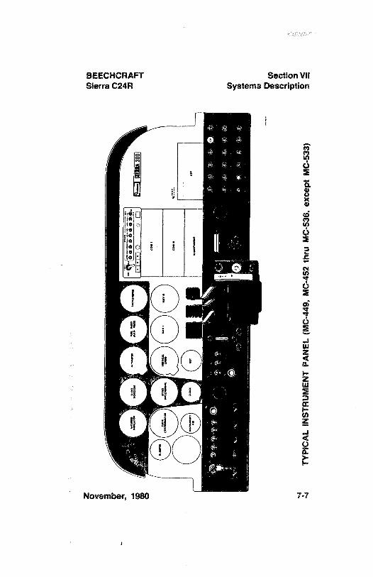
BEECHCRAFT Section VilSierra C24R Systems Description
ed O
o
November, 1980 7.7
i
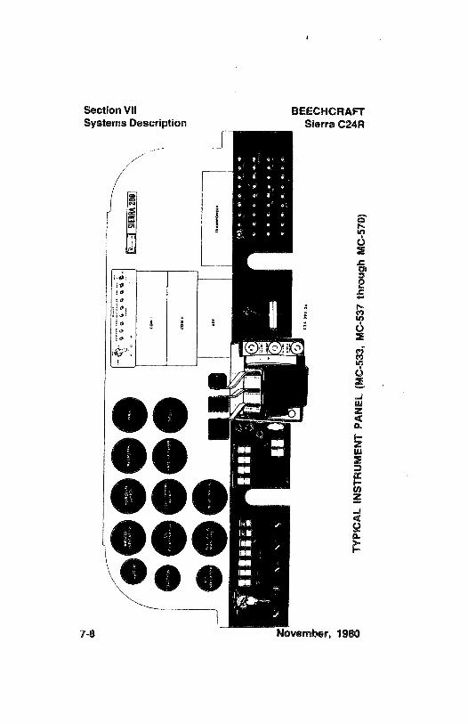
Section VII BEECHCRAFTSystems Description Sierra C24R
OOOO
OOeee7-8 November, 1980
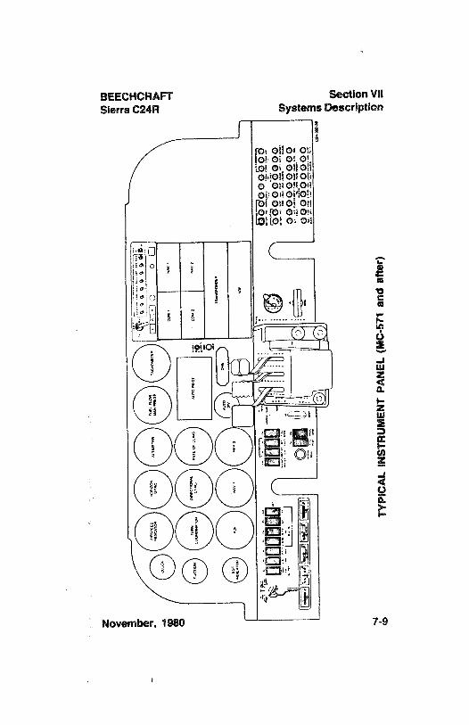
BEECHCRAFT Section VIISierra C24R Systems Description
foi ollor onlot oi of o't.ol oi oliolioMoliononO ON OROMoisonodon
i OBO! Oilfot OR08Lo o o!!
November, 1980 7.9
i
Section VII BEECHCRAFTSystems Description Sierra C24R
located on the left subpanel, and the circuit breakergrouping is on the right subpanel.
SWITCHES
The magneto/start switch, and switches for the battery,alternator, pitot heat, auxiliaryfuel pump, and landing gearare located on the left subpanel.
CIRCUIT BREAKERS
The circuit breakers are located on the right subpanel.
FLIGHT INSTRUMENTS
The standard flight instruments are grouped in a "T"pattern on the main panel for the best presentation for thepilot. The magnetic compass is attached to the uppercenter of the windshield.
Ram air pressure for the airspeed indicator enters throughthe pitot tube under the left wing. Static air pressure for thealtimeter, vertical speed, and airspeed indicator is suppliedby a static port on each side of the fuselage, just aft of thebaggage area.
I MC-449, MC-452 through MC-536 except MC-533:
The instruments are illuminated either by an overheadflood light or post lights. The flood light is controlled by artieostat switch located below the power quadrant on thepedestal, while the post light installation is controlled by arheostat switch on the left subpanel.
IMC-533, MC-537 and after:
The instruments are illuminated either by an overhead
7-10 December, 1982
BEECHCRAFT Section VIISierra C24R Systems Description
flood light or post lights. The rheostat switches controllingthese lights are located on the pedestal, below the powerquadrant.
GROUND CONTROL
Steering is accomplished by the use of rudder pedalsthrough a spring-loaded linkage connecting the nose gear tothe rudder pedals. The nose-gear maximum travel is
28°±
2°
left and right. A hydraulic shimmy damper on the nose gearyoke compensates for any tendency to shimmy. Toe brakesmay be used to aid in steering the airplane on the ground.
The minimum wing-tip turning radius, using full steering, onebrake, and partial power, is 26 feet 10 inches.
WING FLAPS
MANUAL
The four-position flaps are operated by a manual leverlocated between the front seats. As the handle is raised tolower the flaps, a definite detent and click of the thumbrelease button will be felt at the 15°, 25°, and
35°flap
extended positions. To retract the flaps, depress the thumbbutton and lower the handle to the floor. The thumb buttondoes not need to be depressed, nor should it be, to extendthe flaps.
ELECTRIC
The electric wing flaps are controlled by a three-positionswitch, UP, OFF, and DOWN, located to the right of thepower quadrant. The switch must be pulled out of detent
December, 1982 7-11
Section Vil BEECHCRAFTSystems Description Sierra C24R
before it can be repositioned. An indicator, locatedadjacent to the flap handle switch, has markings for UP, 10DEGREES,
15° (green radial), 20 DEGREES, and DOWN.The green radial is placed on the indicator at the 15°
position to denote flap position for takeoffs.
Limit switches automatically interrupt power to the electricmotor when the flaps reach the extremes of travel.Intermediate flap positions can be obtained by placing thethree-position switch in the OFF position during flapextension or retraction.
EFFECT OF FLAPS ON FLIGHT
TAKEOFF
Retraction of take-off flaps(15°
for takeoff), during climb-out, requires no change in trim and only light changes incontrol forces. The light forces dissipate without change intrim or significant change in airspeed.
CAUTION
Establish recovery altitude and recovery powerbefore retracting flaps during slow flight,particularly during recoveries from approachconfigurations.
LANDING GEAR
The retractable tricycle landing gear, fabricated frommagnesium casting and aluminum forgings, uses rubberdisks for shock absorption. The gears are identical exceptfor the pivoting action during retraction and the steeringprovisions of the nose gear. Retraction and extension ofthe gear is accomplished through the use of an electric-driven hydraulic pump and hydraulic system. The landinggear may be hydraulically extended or retracted, and maybe lowered manually. (See Emergency ExtensionProcedures.)
7-12 December, 1982
BEECHCRAFT Section VIISierra C24R Systems Description
CONTROL SWITCH
The landing gear is controlled by a two-position switch onthe left side of the subpanel. The switch handle must bepulled out of the safety detent before it can be moved to theopposite position.
POSITION INDICATORS
The landing gear position indicator lights are located belowthe landing gear switch handle. Three green lights, one foreach gear, are illuminated whenever the landing gears aredown. The red light illuminates any time one or all of thelanding gears are in transit or in any intermediate position.All of the lights will be out when the gears are up andlocked. Pressing the warning light test button on theinstrument panel will verify the landing gear lamps areilluminating. The intensity of the lamps can be controlled byturning the lens holder on each lamp.
TIME-DELAY RELAY (MC-674 and after)
Landing gear retraction operation is protected by a time-delay relay which will disengage electrical power to thehydraulic pump motor after 30 seconds of continuous pumpoperation. If the landing gear in-transit light remainsilluminated, it indicates improper response of the landinggear. The time-delay relay can be reset by moving thelanding gear switch handle to the down position. Thelanding gear and retract system should be checked beforethe next flight.
SAFETY RETRACTION SWITCH
To prevent inadvertent retraction of the landing gear on theground, a safety pressure switch located in the pitot system,
November, 1980 7-13
Section VII BEECHCRAFTSystems Description Sierra C24R
deactivates the hydraulic pressure pump circuit when theimpact air pressure is below 68 to 72 mph, (59 to 63 kts).
WARNING
Never rely on the safety switch to keep thegear down during taxi, take-off roll, or landingroll. Always make certain that the landing gearswitch is in the down position during theseoperations.
WARNING HORN
With the landing gear retracted, if the throttle is retardedbelow approximately 12 inches mercury manifold pressure,a warning horn will sound continuously.
CIRCUIT BREAKER
The landing GEAR MOTOR circuit breaker is located onthe right subpanel. This circuit breaker is a pull-and-resettype breaker. A white circle identifies this circuit breaker.The breaker will pop out under overload conditions. Theremainder of the landing gear circuitry is protected by apush-to-reset circuit breaker marked GEAR IND.
WARNING
The landing gear system will be inoperative ifthe GEAR IND circuit breaker is pulled.
EMERGENCY EXTENSION
The landing gear can be extended by turning the hydraulicpressure bypass valve
90°counterclockwise. The valve is
located on the floor in front of the pilot's seat. When thesystem pressure is released the gear will fall into the down-
7-14 November, 1980
BEECHCRAFT Section VilSierra C24R Systems Description
and-locked position. This extension procedure is outlined inEMERGENCY PROCEDURES Section.
NOTERepeated emergency extension of the landinggear may deplete the hydraulic fluid reservoirsupply.
BRAKES
The brakes on the main landing gear wheels are operatedby applying toe pressure to the top of the rudder pedals.The parking brake push-pull control is located on the leftsubpanel. To set the parking brakes, pull the control out andpump both toe pedals until solid resistance is felt. Push thecontrol in to release the brakes.
CAUT/ON
Install wheel chocks and release the parkingbrake if the airplane is to be left unattended.Changes in ambient temperature can cause thebrakes to release or to exert excessivepressures.
LANDING GEAR SAFETY EXTENSION SYSTEM
The landing gear safety system is designed to prevent "gearup" landings. The system is to be used as a safety deviceonly; normal usage of the landing gear position switch ismandatory.
To extend the landing gear, place the landing gear safetysystem ON-OFF switch in the ON position. The landing gearwill be automatically extended when: (1) the airspeed isbelow approximately 115 mph (100 kts) IAS and (2) theengine is operating at a throttle position corresponding to
November, 1980 7-15
Section VII BEECHCRAFTSystems Description Sierra C24R
approximately 18 inches or less of manifold pressure.
To retract the landing gear, place the landing gear safetysystem ON-OFF switch in the ON position. The landing gearwill not retract unless: (1) the landing gear position switch isin the UP position, (2) the airspeed is above approximately72 mph (63 kts) IAS and (3) the engine is operating at athrottle position corresponding to approximately 20 inchesor more of manifold pressure.
If landing gear retraction is desired when the throttleposition corresponds to 20 inches of manifold pressure orless, the landing gear safety system ON-OFF switch mustbe placed in the OFF position before placing the landinggear position switch in the UP position.
In the event of an emergency, automatic extension of thelanding gear may be prevented by placing the landing gearsafety system ON-OFF switch in the OFF position, thusdeactivating the safety system.
BAGGAGE COMPARTMENT
A 19.5-cubic-foot baggage space is located behind the 3rdand 4th seats. In addition, a hat shelf, near the top of thecabin enclosure provides an out-of-the-wayspace for lightmiscellaneous articles. Both the baggage compartment andhat shelf are accessible in flight.
WARNINGDo not carry hazardous material anywhere inthe airplane.
Do not carry children in the baggagecompartment unless secured in a seat.
7-16 November, 1980
BEECHCRAFT Section VIISierra C24R Systems Description
SEATS, SEAT BELTS, AND SHOULDER HARNESSES
SEAT ADJUSTMENT
To adjust either of the front seats, pull to the right and up onthe release knob below the left seat corner and slide theseat forward or aft, as desired. Make certain the seat islocked securely in place after adjustment. The backs of theist, 2nd, 3rd, and 4th seats can be placed in any of 3positions. The 5th and 6th bench-type children's seat is notadjustable. Outboard armrests for the front seats areattached to the cabin doors.
SEAT BELTS
All seats are provided with seat belts having a lever-action,quick-release, metal buckle. The seat belt length can beshortened or lengthened by allowing the excess belt to pullthrough the end of the buckle. Holding the buckle at a rightangle to the belt releases the binding action, allowing thebelt to slip.
SHOULDER HARNESSES
The shoulder harness is a standard installation for all seatsand should be used with the seats in the upright position.The spring loading at the inertia reel keeps the harnesssnug, but will allow normal movement during flightoperations. The inertia reel is designed with a locking devicethat will secure the harness in the event of sudden forwardmovement or an impact action. The strap is worn over theshoulder and down across the body, where it is fastened bya metal loop to the seat belt buckle. The inertia reels for thefront and middle seats are attached to the lower cabinsidewall structure at the att edge of the respective seat. Theinertia reel is covered with an escutcheon, and the strapruns up from the reel to a looped fitting attached to the
November, 1980 7-17
l
Section Vil BEECHCRAFTSystems Description Sierra C24R
window frame just aft of the seat. For stowing theseshoulder harness straps, stowage attach points areprovided adjacent to the inertia reel on the cabin sidewall.For the 5th and 6th seats the strap is contained in an inertiareel attached to the aft cabin bulkhead structure behind thehat shelf.
WARNING
The seat belt is independent of the shoulderharness. However, the shouldar harness maybe used only when the seat belt is fastened.
Occupants shorter than 4'7 are not to useshoulder harness.
DOORS AND EXITS
FORWARD CABIN DOORS
The airplane has a conventional cabin door on each side ofthe fuselage adjacent to the forward seats. When closed,the outside cabin door handle is spring-loaded to fit into arecess in the door. The door may be locked with a key. Toopen the door from the outside, grasp the flush handle andpull until the door opens. To close the cabin doors from theinside, grasp the armrest attached to the door and firmly pullthe door closed. Opening the storm window will alleviatepressure inside the cabin as the door is being closed. Pressfirmly outward at the aft edge of the door. If any movementof the door is detected, completely open the door and closeagain following the above instructions. To open the doorfrom the inside, grasp the flush door release handle and pulluntil door latch releases.
7-18 November, 1980
BEECHCRAFT Section VIISierra C24R Systems Description
AFT UTILITY DOOR
A utility door, aft of the cabin door on the left side of thefuselage, is provided for loading cargo or passengers in theaft cabin. This door can be opened from both inside and out.To open the door from the outside, grasp the flush handleand pull until door opens. To open from the inside pull outon the pin adjacent to the door handle, then rotate thehandle counterclockwise until the door opens. This door canbe locked with a key.
EMERGENCY EXITS
An emergency exit can be accomplished through any of thethree doors.
CONTROL LOCKS
A control lock is provided, with the loose tools, to preventmovement of the control column and impairs access to themagneto/start switch.
To install the Control Lock:1. Rotate control wheel and move control column so the
holes in the control column hanger and the controlcolumn will align to accept the pin.
2. Push the control column lock pin through the holeprovided in the controlcolumn hanger and into the holein the underside of the control column tube assembly.
3. Ensure positive retention of the lock pin by positioningthe hook over the. control column.
WARNING
Before starting engine, remove the control lockby reversing the above procedure.
November, 1980 7-19
i
Section VII BEECHCRAFTSystems Description Sierra C24R
ENGINE
The BEECHCRAFT Sierra 200 C24R is powered by aLycoming lO-360-A1B6 four-cylinder, horizontally opposed,fuel-injected engine rated at 200 horsepower. Normaloperating engine speed range is 2350 to 2700 rpm with arestricted operating range between 2100 and 2350 rpm.
ENGINE CONTROLS
The control levers are grouped along the upper face of thepower quadrant. Pushing forward on a control increases,while pulling back decreases the control's appropriatefunction. Their knobs are shaped to government standardconfiguration so they can be identified by touch. Thecontrols are centrally located for ease of operation fromeither the pilot's or copilot's seat. A controllable frictionlever, located to the right of the control levers, is provided toprevent creeping.
ENGINE INSTRUMENTS
The engine instrument cluster is located on the lower leftsubpanel and includes the left fuel quantity indicator, anammeter, oil temperature, oil pressure and the right fuelquantity indicator. The tachometer and manifoldpressure/fuel flow indicators are located above the enginecontrols.
MAN/FOLD PRESSURE AND FUEL FLOW /ND/CATOR
The manifold pressure portion of this instrument indicatesthe pressure of the fuel-air mixture entering the enginecylinders and is calibrated in inches of mercury. Byobserving the manifold pressure gage and adjusting thepropeller and throttle controls, the power output of theengine can be adjusted to any of the power settingsdesignated in the Cruise Power Setting tables in thePERFORMANCE Section.
7-20 November, 1980
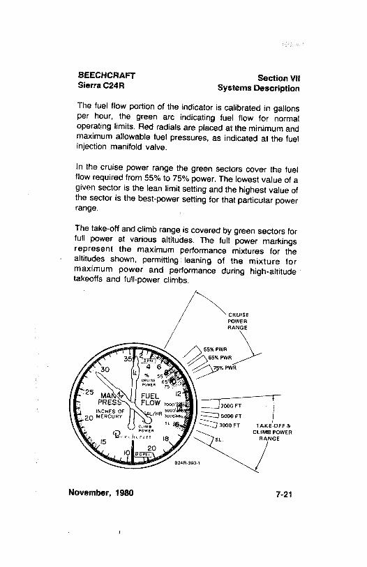
BEECHCRAFT Section VIISierra C24R Systems Description
The fuel flow portion of the indicator is calibrated in gallonsper hour, the green arc indicating fuel flow for normaloperating limits. Red radials are placed at the minimum andmaximum allowable fuel pressures, as indicated at the fuelinjection manifold valve.
In the cruise power range the green sectors cover the fuelflow required from 55% to 75% power. The lowest value of agiven sector is the lean limit setting and the highest value ofthe sector is the best-power setting for that particular powerrange.
The take-offand climb range is covered by green sectors forfull power at various altitudes. The full power markingsrepresent the maximum performance mixtures for thealtitudes shown, permitting leaning of the mixture formaximum power and performance during high-altitudetakeoffs and full-power climbs.
CRUISEPOWERRANGE
55% PWR
35 sesp·
,
65% PWR
4 6 % PWR
25 MANA FUEL 2PRESS FLOW oo yooo py
20ECHCRO /HR 6000 FT
cues " 16 3000 FT TAKEDFF &owen CLIMB POWER
meetheralt IS SL. RANGE
2010 wwsp824R 390 1
November, 1980 7-21
Section Vil BEECHCRAFTSystems Description Sierra C24R
EXHAUST GAS TEMPERATURE IND/CATOR (EGT)
This installation provides for sensitive and rapid indication ofexhaust gas temperature to assist in adjusting the fuellairmixture during cruise.
ENGINE BREAK-IN INFORMATION
New engines have been carefully run-in by the enginemanufacturer. However, the engine should be operated onstraight mineral oil for a minimum of 50 hours or until oilconsumption stabilizes. After the first 25 hours of operation,drain and replace the mineral oil. A change to an approvedengine oil should be made after the break-in period. Refer toLycoming Engine Operator's Manual.
NOTE
In order to promote proper ring seating, cruisepower settings of 65% to 75% should be useduntil a total of 50 hours has accumulated or untiloil consumption has stabilized. Thisrecommendation is applicable to in-serviceengines following cylinder replacement or top-overhaul of one or more cylinders, as well as tonew engines.
COWLING
The cowling is the split-type and is removable to expose theengine and mount assemblies.
7-22 November, 1980
BEECHCRAFT Section VilSierra C24R Systems Description
LUBRICATION SYSTEM
The engine oil system is the wet-sump type and has an 8-quart capacity. Oil operating temperatures are controlled byan automatic thermostat bypass control.The bypass controlwill limit oil flow through the oil cooler when operatingtemperatures are below normal, and will permit the oil tobypass the cooler if it should become blocked.
INDUCTION SYSTEM ICING
The possibility of induction system icing is reduced by thenon-icing characteristics of the fuel-injected engine andautomatic alternate air source. The alternate air door willopen automatically if the air intake or filter becomesobstructed.
STARTER
A magneto/start switch, located on the subpanel to the leftof the pilot's control column, incorporates R(right), L(left)and BOTH magneto positions in addition to the normalOFF and START positions. After activation of the starterthe spring-loaded switch returns to the BOTH positionwhen released. Battery switch and alternator switch aregrouped on the subpanel to the right of the pilot's controlcolumn.
The warning light placarded STARTER ENGAGED (MC-731 and after) illuminates whenever electrical power isbeing supplied to the starter. If the light remains illuminatedafter starting, the starter relay has remained engaged, andloss of electrical power and possible equipment damagewill eventually result. Turn the BATTERY & ALT and ALTSwitches OFF. If in flight, land as soon as practical. If thelight does not illuminate during starting, the indicatorsystem is inoperative and the ammeter must be monitored
November, 1980 7-23
Section VII BEECHCRAFTSystems Description Sierra C24R
to ensure that the starter does not remain energized afterreleasing the magneto/start switch.
PROPELLER
Installed as standard equipment is a constant-speed,variable-pitch, 76 -diameter propeller with two aluminumalloy blades. The pitch setting at the 30-inch station is
14.4°
Iow and27.0° to 31.0° high pitch. Normal operating range is
2350 to 2700 rpm with a restricted operating range between2100 and 2350 rpm.
Propeller rpm is controlled by a single-action,engine-drivenpropeller governor which regulates hydraulic oil pressure tothe hub. The propeller control on the power quadrant allowsthe pilot to select the governor's rpm range. Governor-boosted oil pressure holds the propeller blades in a highpitch (low rpm) position during normal cruise operation. If oilpressure is lost, the propeller willgo to the full high rpm (lowpitch) position.
FUEL SYSTEM
The airplane is designed for operation on grade 100 (green)or 100LL (blue) aviation gasoline.
FUEL TANKS
Fuel tanks located in each wing have a nominal capacity of29.9 gallons each for a total of 59.8 gallons. In the fillerneck of each tank is a visual measuring tab whichfacilitates partial filling of the fuel system. When the fueltouches the bottom of the tab it indicates 15 gallons of fuel,and when filled to the slot in the tab it indicates 20 gallons.The pilot must visually check the fuel levet during preflight
7-24 November, 1980
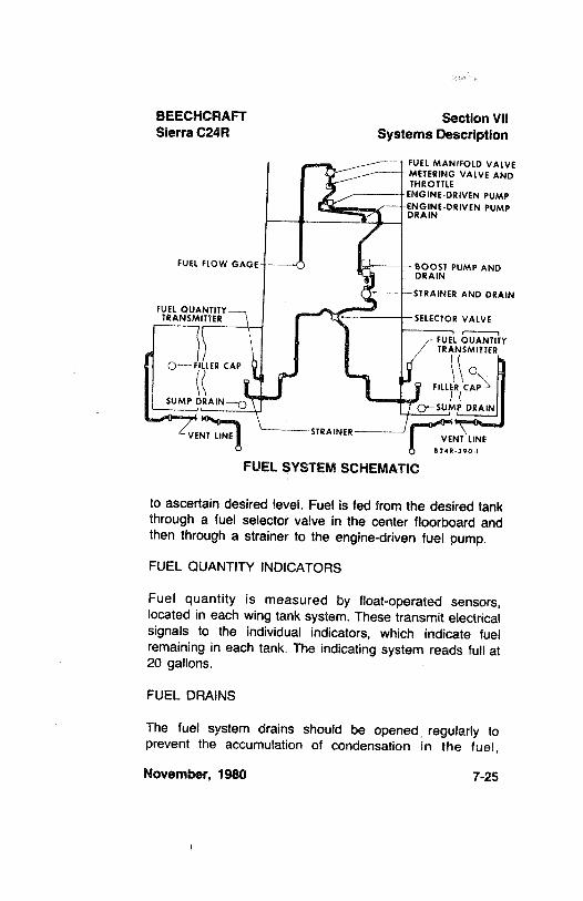
BEECHCRAFT Section VilSierra C24R Systems Description
FUEL MANIFOLD VALVEMETERING VALVE ANDTHROTTLE
ENGINE-DRIVEN PUMPENGINE-DRIVEN PUMPDRAIN
FUEL FLOW GAGE - BOOST PUMP ANDDRAIN
-STRAINER AND DRAIN
A T--
-SELECTOR VALVE
-FUEL QUANTITYTRANSMITTER
O-FILLER CAP O
SUMP DRAIN-Q
STRAINERVENT UNE VENT LINE
624R-390-I
FUEL SYSTEM SCHEMATIC
to ascertain desired level. Fuel is fed from the desired tankthrough a fuel selector valve in the center floorboard andthen through a strainer to the engine-driven fuel pump.
FUEL QUANTITY INDICATORS
Fuel quantity is measured by float-operated sensors,located in each wing tank system. These transmit electricalsignals to the individual indicators, which indicate fuelremaining in each tank. The indicating system reads full at20 gallons.
FUEL DRAINS
The fuel system drains should be opened regularly toprevent the accumulation of condensation in the fuel,
November, 1980 7-25
Section VII BEECHCRAFTSystems Description Sierra C24R
especially during periods of warm days and cool nights.They should also be opened before each flight not only tocheck for condensation but also to inspect for fuelcontamination.
Wing Drains
Wing sump drains on MC-449, MC-452 through MC-536except MC-533, protrude through the wing skin and areopened by pushing them upward to release the fuel. Thistype of valve can be locked open by pushing upward toopen it, then rotating it clockwise to lock it. To close thevalve, press upward and rotate counterclockwise. Whenreleased, the valve will close. Check for proper seating toprevent fuel loss.
On MC-533, MC-537 and after, the wing drains have flush-type valves and are opened by using the combination fueldrainlemergency landing gear extension tool provided withthe loose tools. It is normally kept in the pocket on the pilot'sdoor. To open the drain valve, insert the tab end of the toolinto the opening in the center of the valve and push upward.Removing the tool will close the valve. This type of draincan be locked open by pushing upward with the tool androtating counterclockwise. To close the valve, press upwardwith the tool in place and rotate clockwisebefore removingthe tool. Make certain the valve is seated to prevent loss offuet
Low Spot Drain
The fuel system low spot drain in the bottom of the fuel filtershould also be drained frequently. It is located on the lowerportion of the firewall on the forward side and protrudesthrough the lower skin. This drain can be locked open byturning clockwise until it locks. To close the drain, rotatecounterclockwise and the valve will snap shut.
7-26 November, 1980
BEECHCRAFT Section VIISierra C24R Systems Description
FUEL BOOST PUMPThe electric fuel boost pump, controlled by an ON-OFFtoggle switch on the pilot's subpanel, provides pressure forstarting and emergency operation. The fuel boost pumpprovides sufficient pressure for engine operation, shouldthe engine-driven pump fail.
FUEL TANK SELECTIONThe fuel selector valve handle is located on the floorboardsbetween the pilot and copilot seats. Takeoffs and landingsshould be made using the tank that is more nearly full.
NOTE
On serials MC-696 and after, or on airplaneswhich have complied with BEECHCRAFT S.I.No. 1095, a fuel selector stop has been addedto the selector valve guard. The fuel selectorstop minimizes the possibility of inadvertentlyturning the fuel selector valve to the OFFdetent position. The stop is a spring whichmust be depressed before the selector valvehandle can be rotated to the OFF position.
If the engine stops because of insufficient fuel, refer to theEMERGENCY PROCEDURES Section for the Air Startprocedures.
FUEL REQUIRED FOR FLIGHT
It is the pilot's responsibility to ascertain that the fuelquantity indicators are functioning and maintaining areasonable degree of accuracy, and to be certain of amplefuel for a flight. Takeoff is prohibited if the fuel quantityindicators do not indicate above the yellow arc. The capsshould be removed and fuel quantity checked to give thepilot an indication of fuel on board. The airplane must be
November, 1980 7-27
Section VII BEECHCRAFTSystems Description Sierra C24R
approximately level for visual inspection of the tank. Fuelshould be added so that the amount of fuel will be not lessthan is required for takeoff. Plan for an ample margin offuel for any flight.
ELECTRICAL SYSTEM
The system circuitry is the single-wire, ground-return type,with the airplane structure used as the ground return. Thebattery, alternator, fuel boost, and magneto/start switchesare located on the left subpanel. The circuit breaker panel,located on the right subpanel, contains the protective circuitbreakers for the various electrical systems. Some switch-type circuit breakers are located on the left subpanel.
In addition, there is an in-line fuse in the rotating beaconwire and in the strobe light wire forward of the left subpanel,with spare fuses adjacent to the fuse holder. There is also afuse on the left side of the quadrant pedestal for the electricclock (if installed), or an in-line fuse near the battery box.
BATTERY
14-VOLT SYSTEM
A 12-volt battery is located in the aft fuselage. Batteryservicing procedures are described in the LANDING,SERVICING AND MAINTENANCE Section.
28-VOLT SYSTEM
One 24-volt battery, or two 12-volt batteries in series, arelocated in the aft fuselage. The two 12-volt batteries inseries are of a shape and size that they will both fit in thesame battery compartment which is provided for the 24-volt
battery. Battery servicing procedures are described in theHANDLING, SERVICING AND MAINTENANCE Section.
7-28 November, 1980
BEECHCRAFT Section VilSierra C24R Systems Description
ALTERNATOR
14-VOLT SYSTEM
The alternator maintains its full-rated 60-ampere output atcruise engine rpm, and uses a voltage regulator to adjustalternator output.
Since the alternator is not self-exciting,dual switches arerequired to activate the circuit. The switch placardedBATTERY & ALT, when placed in the ON position, will onlyactivate the battery circuit. When this switch is on and theALT (FIELD) switch is placed in the ON position, thealternator is excited by power from the airplane battery.When the BATTERY & ALT switch is in the OFF position,the alternator will be off regardless of the ALT (FIELD)switch position. The alternator-field circuit breaker andalternator-output circuit breaker are located on the rightsubpanel (MC-449, MC-452 through MC-642). On airplanesMC-643 through MC-673 (and airplanes MC-449, MC-452through MC-642 with installation of Beech Kit No. 23-3009-1S) the alternator circuit is protected by an alternator-fieldcircuit breaker on the right subpanel, and an alternator-output current limiter on the firewall.
28-VOLT SYSTEM (MC-674 and after)
The 28-volt alternator is rated at 60 amps nominal outputat cruise engine rpm. A self-exciting feature provides foractivation of the alternator independent of battery powerwhen the engine reaches a speed of 1200 to 1500 rpm. Aswitch on the pilot's subpanel placarded ALT FIELDcontrols the alternator circuit. Circuit breakers for thealternator are located on the right subpanel.
December, 1982 7-29
Section VII BEECHCRAFTSystems Description Sierra C24R
EXTERNAL POWER RECEPTACLE
The external power receptacle is optional on this airplane. Ifinstalled,it is located on the right side of the fuselage (MC-449, MC-452 through MC-772) or on the left side of thefuselage (MC-773 and after), aft of the wing. Airplanesequipped with a 14-volt electrical system require a powerunit set to 13.75 to 14.25 volts, while those equipped with a28-volt electrical system require a setting of 27.75 to 28.25volts.
CAUTION
On 14-volt airplanes, the power pin for externalpower is connected directly to the battery andcontinually energized. Turn off battery andalternator switches and all electrical andavionics switches when connecting theauxiliary power unit plug. Assure correctpolarity (negative ground) before connectingauxiliary power unit. Turn on the battery switchbefore turning on the auxiliary power unit.
On 28-volt airplanes, a reverse polarity diodeprotection system is between the externalpower receptacle and the main bus. Withexternal power applied, the bus is powered.Turn on the battery switch only, with all otherswitches including avionics switches off, whenconnecting the auxiliary power unit. Assurecorrect polarity before connecting externalpower.
IWhen auxiliary power is desired, connect the clamps of thepower cable to the remote power source, ensuring properpolarity. Turn OFF the ALT switches and ensure that all
7-30 December, 1982
BEECHCRAFT Section VIISierra C24R Systems Description
avionics equipment is OFF, and then turn ON the BATTswitch. Insert the power cable plug into the receptacle, turnon auxiliary power unit, and start engine using the normalstarting procedures.
LIGHTING SYSTEMS
INTERIOR LIGHTING
Lighting for the instrument panel is controlled by a rheostatswitch located on the pilot's subpanel to the left of thecontrol column (MC-449, MC-452 through MC-536 exceptMC-533), or on the pedestal below the power quadrant(MC-533, MC-537 and after). The cabin dome light isoperated by an ON-OFF switch adjacenÏto the light. Theoverhead instrument lighting and the map light (MC-689,MC-702 and after do not have a map light installed) arecontrolled by a rheostat switch located on the pedestal,below the power quadrant.
EXTERIOR LIGHTING
The switches for all of the exterior lights are located on thepilot's left subpanel. Each circuit is protected by a circuitbreaker switch, circuit breaker, or fuse.
The exterior lights consist of navigation lights on the wingtips and rudder, a landing light on the left outboard wing,optional taxi lights on both outboard wings, and a rotatingbeacon on the vertical stabilizer. The landing light shouldbe used for approach only, and the taxi lights should beused for ground maneuvering only. For longer battery andlamp life, use the landing light and taxi lights sparingly;avoid prolonged operation which could cause overheatingduring ground maneuvering.
December, 1982 7-31
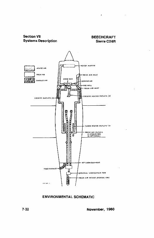
Section VII BEECHCRAFTSystems Description Sierra C24R
HEATER AtR
FRESH AIR FRESH AIR INLET
EXHAUST AIRMtXER
DEFROSI AIR
WAtt
FRESH AIR INLET
cocKPIT HEATER OUTLETS (2)COCKPIT OUTLETS (2)
CASIN HEATER OUTLETS (3)
FRESN AIR QUILErs(4 STANOARD)(6 OPTIONAL)
AFT CABIN BULKHEAD
FIXED EKNAUSI'
OPIIONAL VENiitAfiON FAN
FRESH AIR INTAKE (DORSAL FIN)
ENVIRONMENTAL SCHEMATIC
7-32 November, 1980
BEECHCRAFT Section VIISierra C24R Systems Description
NOTE
Particularly at night, reflections from rotatinganti-collision lights or strobe lights on clouds,dense haze or dust can produce opticalillusions and intense vertigo. Such lights, wheninstalled, should bd turned off before enteringan overcast; their use may not be advisableunder instrument or limited VFR conditions.
ENVIRONMENTAL SYSTEMS
CABIN HEATING
Air for warming the cabin and defrosting the windshieldenters through an intake on the forward engine baffle,passes through the heater and into a mixer box where it isblended with cold air to obtain the desired cabintemperature. Hot or cold air may enter the cabin throughthe firewall outlets. The knob marked CABIN AIR regulatesthe quantity of air entering the cabin through this firewalloutlet. With the CABIN AIR knob in, pull out the CABINHEAT knob for heated air and push it in for fresh air. Thereare 4 outlets for cabin heat distribution in the standardinstallation; however, 5 outlets are provided when theoptional children's seat is installed. Pull out the DEFROSTknob for maximum defrost. Under extremely coldconditions, heating in the back seats can be improved bypartially pulling the defrost knob.
VENTILATION
Fresh air for the cabin enters through two grill-type infetsimmediately forward of the windshield and a scoop-typeinlet on the dorsal fin. The two grill-type inlets supply air tothe eyeball outlets on the cabin sidewalls between the
December, 1982 7-33
Section VII BEECHCRAFTSystems Description Sierra C24R
instrument panel and cabin doors. The scoop-type inletsupplies air to the four or six overhead eyeball outlets. Airflow through the eyeball outlets is regulated by rotating theoutlet. An optional fan, controlled by a switch below theIpowerquadrant (MC-449, MC-452 thru MC-536, exceptMC-533) or on the left subpanel (MC-533, MC-537 andafter), facilitates ventilation for ground operation. The fanshould be off when the airplane is airborne.
EXHAUST VENT
A fixed exhaust vent is located in the aft cabin for flow-through ventilation.
PITOT AND STATIC SYSTEMS
PITOT SYSTEM
The pitot system provides a source of impact air foroperation of the airspeed indicator. The pitot mast is locatedon the leading edge of the left wing.
P/TOT HEAT
The pitot mast is provided with an electric heating elementwhich is turned on and off with a switch on the instrumentpanel. The switch should be ON when flying in visiblemoisture. It is not advisable to operate the pitot heatingelement on the ground except for testing or for shortintervals of time to remove ice or snow.
NORMAL STATIC AIR SYSTEM
The normal static air system provides a source of static airto the flight instruments through a flush static fitting on each
7-34 December, 1982
BEECHCRAFT Section VIISierra C24R Systems Description
side of the aft fuselage. A union located inside a cover plateon the belly of the airplane provides a drain point to removemoisture from the system.
EMERGENCY STATICAIR SYSTEM
An emergency static air source may be installed to provideair for instrument operation should the static ports becomeblocked. Refer to the EMERGENCY PROCEDURESSection for procedures describing how and when to use thissystem.
VACUUM SYSTEM
Vacuum for air-driven gyroscopic flight instruments andother air-driven equipment is supplied by an engine-drivenvacuum pump. An adjustable relief valve controls suction bybleeding outside air into the vacuum pump.
A suction gage indicates system vacuum in inches ofmercury. This instrument is located on the pilot's side of theinstrument panel. The vacuum should be maintained withinthe green arc for proper operation of the air-driveninstruments.
STALL WARNING SYSTEM
WARNING
With the BATTERY & ALT switch in the OFFposition the stall warning horn is inoperative.Airplane certification requires the stall warningsystem to be on during flight except inemergency conditions as stated in Section Ill.
December, 1982 7-35
Section VII BEECHCRAFTSystems Description Sierra C24R
A stall warning horn located in the overhead speakerconsole is factory set to sound a warning 5 to 7 mph abovea stall condition and continues steadily as the airplaneapproaches a complete stall. The stall warning horn,triggered by a sensing vane on the leading edge of the leftwing, is equally effective in all flight configurations and at allweights.
7-36 December, 1982
BEECHCRAFTSierra C24R
SECTION VIII
HANDLING, SERVICINGAND MAINTENANCE
TABLE OF CONTENTS
SUBJECT PAGE
Introduction.................... ......................8-3
Publications........................ ........................8-4
Airplane inspection Periods ..............................................
8-4Preventative Maintenance That May Be Accomplished
By A Certificated Pilot......... ........
8-5Alterations or Repairs to Airplane...................................... 8-5
Ground Handling....................... .....................
8-6Towing ...................... .......................
8-6Parking........................... ......................
8-7Control Column Lock Pin............................................... 8-7Tie-Down.......
.......
8-7Jacking...................... . . ......................
8-8
Flyable Storage - 7 to 30 DaysMooring ..................... . .. .......................
8-9Fuel Cells ....................... .......................
8-9Fli<jhtControl Surfaces....................... .......................
8-9Grounding ..................... . .......................
8-9Pitot Tube................... ... .........................
8-9Windshield and Windows ....................... ......................
8-9During Flyable Storage......................... ............ ........
8-10Preparation for Service.................... .. ...................
8-10Prolonged Out of Service Care .......................................
8-10
November, 1980 8-1
Section VIII BEECHCRAFTHandling, Serv & Maint Sierra C24R
External Power Receptacle............................................. 8-11Checking Electrical Equipment.................................... 8-12
ServicingFuel System........................ .......................
8-12OilSystem........................ . ........................
8-14Battery......................... ........................
8-14Tires.......................... ........................
8-15ShimmyDamper ....................... . ..........................
8-16Brakes........................ . .....................
8-16Induction Air Filter ...................... . .....................
8-16Vacuum System........................ . .....................
8-17Propeller Blades........................ ......................
8-17
Minor MaintenanceRubber Seals ....................... ........................
8-18Altemator ....................... .........................
8-18Mag netos .......................... .........................
8-19
CleaningExterior Paint Finishes ...................... . .......................
8-19Lacquer Paint Finishes ............................................
8-19Urethane Paint Finishes ..........................................
8-20Windshield and Windows ............................................
8-21Interior.......................... .........................
8-21Engine.......................... . .......................
8-22
Lubrication........................... ........................
8-22Lubrication Points....................... .......................
8-23
Recommended ServicingSchedule................................ 8-29Consumable Materials........................ ........................
8-32Approved Engine Oils .......................... ........................
8-34Bulb Replacement Guide................................................ 8-36Overhaul and Replacement Schedule ............................
8-37
8-2 November, 1980
BEECHCRAFT Section VIIISierra C24R Handling, Serv & Maint
INTRODUCTION
The purpose of this section is to outline the requirements formaintaining the airplane in a condition equal to that of itsoriginal manufacture. This information sets the timefrequency intervals at which the airplane should be taken toa BEECHCRAFT Aero or Aviation Center or InternationalDistributor or Dealer for periodic servicing or preventivemaintenance.
The Federal Aviation Regulations place the responsibility forthe maintenance of this airplane on the owner and operator,who must ensure that all maintenance is done by qualifiedmechanics in conformity with all airworthiness requirementsestablished for this airplane.
All limits, procedures, safety practices, time limits, servicingand maintenance requirements contained in this handbookare considered mandatory.
Authorized BEECHCRAFT Aero or Aviation Centers orInternational Distributors or Dealers can providerecommended modification, service and operatingprocedures issued by both the FAA and Beech AircraftCorporation, designed to get maximum utility and safetyfrom the airplane.
If a question should arise concerning the care of theairplane, it should be directed to Beech Aircraft Corporation,Liberal Division, Box 300, Liberal, Kansas 67901.Correspondence should contain the airplane serial number,which can be found on the manufacturer's placard, locatedon the right side of the fuselage adjacent to the inboard endof the flap. The placard is visible when the flaps arelowered.
November, 1980 8-3
Section VIII BEECHCRAFTHandling, Serv & Maint Sierra C24R
PUBLICATIONS
The following publications are available throughBEECHCRAFT Aero or Aviation Centers or InternationalDistributors or Dealers.
1. Shop Manual2. Parts Catalog3. Service Instructions4. Various inspection Forms
NOTE
Neither Service Publications, Reissues, norRevisions are automatically provided to theholder of this handbook. For information onhow to obtain "Revision Service" applicable tothis handbook consult a BEECHCRAFT Aeroor Aviation Center, or International Distributoror Dealer, or refer to the latest revision ofBEECHCRAFT Service Instructions No. 0250-010.
AIRPLANE INSPECTION PERIODS
1. FAA Required Annual Inspections.2. BEECHCRAFT Recommended inspection Guide.3. Continuing Care Inspection Guide.4. See "Recommended Servicing Schedule" and
"Overhaul or Replacement Schedule" for furtherinspection schedules.
84 November, 1980
BEECHCRAFT Section VIIISierra C24R Handling, Serv & Maint
PREVENTATIVE MAINTENANCE THAT MAY BEACCOMPLISHED BY A CERTIFICATED PILOT
1. A certificated pilot may perform limited maintenance.Refer to FAR Part 43 for the items which may beaccomplished.
To ensure that proper procedures are followed, obtain aBEECHCRAFT Shop Manual before performing anymaintenance operation.
2. All other maintenance must be performed by licensedpersonnel.
NOTE
Pilots operating airplanes of other than U.S.registry should refer to the regulations of theregistering authority for information concerningpreventative maintenance that may beperformed by pilots.
ALTERATIONS OR REPAIRS TO AIRPLANE
The FAA should be contacted prior to any alterations on theairplane to ensure that the airworthiness of the airplane isnot violated.
NOTE
Alterations and repairs to the airplane must bemade by properly licensed personnel.
November, 1980 8-5
Section VIII BEECHCRAFTHandling, Serv & Maint Sierra C24R
GROUND HANDUNG
The three-view drawing shows the minimum hangarclearances for a standard airplane. Allowances must bemade for any special radio antennas and the possibility ofan under inflated nose tire.
TOWING
CAUT/ON
Extreme care should be used when moving withpower equipment. Should the nose gear beturned in excess of the red limit marks, there isa very good possibility the nose gear steeringyoke and/or linkage may be damaged.
One person can move the airplane on a smooth and levelsurface, using the hand tow bar furnished with the looseequipment. Attach the tow bar to the tow lugs on the nosegear lower torque knee.
Where movement is restricted, two people can pivot theairplane on the main wheels. One person should push onthe wing leading edge or hold the wing tip, while the otheroperates the tow bar.
CAUTION
Do not exert force on the propeller or controlsurfaces. Do not place weight on the stabilatorto raise the nose wheel. Do not attempt to towthe airplane backward by the tail tie-down ring.
8-6 November, 1980
BEECHCRAFT Section VIIISierra C24R Handling, Serv & Maint
PARKING
The parking brake push-pull control is located on the leftside of the lower subpanel. To set the parking brakes, pullthe control out and depress each toe pedal until firm. Pushthe control in to release the brakes.
NOTE
The parking brake should be left off and wheelchocks installed if the airplane is to remainunattended. Changes in ambient temperaturecan cause the brakes to release or to exertexcessive pressures.
CONTROL COLUMN LOCK PIN
1. Rotate the control wheel and move control column sothe holes in the control column hanger and the controlcolumn will align to accept the pin.
2. Push the control column lock pin through the holeprovided in the control columnhanger and into the holein the underside of the control column tube assembly.
3. Ensure positive retention of the lock pin by positioningthe hook over the control column.
TIE-DOWN
It is advisable to nose the airplane into the wind. Three tie-down lugs are provided: one on the lower side of each wingand a third at the rear of the fuselage.
1. Install the control column lock pin.
November, 1980 8-7
Section Vill BEECHCRAFTHandling, Serv & Maint Sierra C24R
2. Chock the main wheels fore and aft.
3. Using nylon line or chain of sufficient strength, securethe airplane at the three points provided. DO NOTOVERTIGHTEN the line at the rear of the fuselageexcessively tight, because the nose may rise andproduce lift due to the angle of attack of the wings.
4. Release the parking brake.
If extremely high winds are anticipated, a vertical tail postcan be installed at the rear tie-down lug, and a tie-down lineattached to the nose gear.
JACKING
Raise the individual gear for wheel and tire removal with ascissors jack under the axle. Also, jack pads are installed tofacilitate landing gear retraction checks. Refer to theBEECHCRAFT Shop Manual for proper procedures.
CAUTION
The landing gear circuit breaker should bepulled and the emergency gear extension valveshould be open to relieve pressure in thehydraulic system, in order to prevent inadvertentretraction of the landing gear when the airplaneis jacked.
8-8 November, 1980
BEECHCRAFT Section VIIISierra C24R Handling, Serv & Maint
FLYABLE STORAGE - 7 to 30 DAYS
MOORING
If airplane cannot be placed in a hangar, tie down securelyat the three points provided. Do not use hemp or manilarope. It is recommended a tail support be used to lightlycompress the nose gear and reduce the angle of attack ofthe wings. Attach a line to the nose gear for additional tie-down.
FUEL CELLS
Fill to capacity to minimize fuel vapor.
FLIGHT CONTROL SURFACES
Lock with internal and external locks.
GROUNDING
Static-ground airplane securely and effectively.
PITOT TUBE
Install cover.
WINDSHIELD AND WINDOWS
Close all windows and window vents. It is recommendedthat covers be installed over the windshield and windows.
November, 1980 8-9
Section VIII BEECHCRAFTHandling, Serv & Maint Sierra C24R
DURING FLYABLE STORAGE
WARNINGBe sure the magnetolstart switch is OFF, thethrottle CLOSED, and mixture control in theIDLE CUT-OFF position before turning thepropeller. Do not stand in the path of propellerblades. Also, ground running the engine for briefperiods of time is not a substitute for turningtheengine over by hand. In fact, the practice ofground running will tend to aggravate ratherthan minimize corrosion formation in the engine.
In a favorable atmospheric environment the engine of anairplane that is flown intermittently can be adequatelyprotected from corrosion by turning the engine over fiverevolutions by means of the propeller. This will dispel anybeads of moisture that may have accumulated and spreadthe residual lubricating oil around the cylinder walls. Unlessthe airplane is flown, repeat this procedure every five days.
After 30 days, the airplane should be flown for 30 minutes ora ground runup should be made long enough to produce anoil temperature within the lower green arc range. Excessiveground runup should be avoided.
PREPARATION FOR SERVICE
Remove all covers, clean the airplane, and give it athorough inspection, particularly landing gear, wheel wells,flaps, control surfaces, and pitot and static pressureopenings.Preflight the airplane.
PROLONGED OUT OF SERVICE CARE
The storage procedures listed are intended to protect theairplane from deterioration while it is not in use. The primary8-10 November, 1980
BEECHCRAFT Section VIIISierra C24R Handling, Serv & Maint
objectives of these measures are to prevent corrosion anddamage from exposure to the elements.
If the airplane is to be stored longer than 30 days refer tothe appropriate airplane shop manual and Avco LycomingService Letter L180.
EXTERNAL POWER RECEPTACLE
The external power receptacle is optional on this airplane. Ifinstalled, it is located on the right side of the fuselage (MC-449, MC-452 through MC-772) or on the left side of thefuselage (MC-773 and after), att of the wing. Airplanesequipped with a 14-volt electrical system require a powerunit set to 13.75 to 14.25 volts, while those equipped with a28-volt electrical system require a setting of 27.75 to 28.25volts.
CAUTION
On 14-volt airplanes, the power pin for externalpower is connected directly to the battery andcontinually energized. Turn off battery andalternator switches and all electrical andavionics switches when connecting theauxiliary power unit plug. Assure correctpolarity (negative ground) before connectingauxiliarypower unit. Turn on the battery switchbefore turning on the auxiliary power unit.
On 28-volt airplanes, a reverse polarity diodeprotection system is between the externalpower receptacle and the main bus. Withexternal power applied, the bus is powered.Turn on the battery switch only, with all otherswitches including avionics switches off, whenconnecting the auxiliary power unit. Assurecorrect polarity before connecting externalpower.
December, 1982 8-11
Section VIII BEECHCRAFTHandling, Serv & Maint Sierra C24R
CHECKING ELECTRICAL EQUIPMENT
Connect an auxiliary power unit as outlined above. Ensurethat the current is stabilized prior to making any electricalequipment or avionics check.
CAUTIONIf the auxiliary power unit has poor voltageregulation or produces voltage transients, theequipment connected to the unit may bedamaged.
SERVICING
FUEL SYSTEM
Use aviation gasoline grades 100 (green)or 100LL (blue).
CAUTION
See Avco Lycoming Service Letter No. L185Aor later revision for operation on alternate fuels.
Two 29.9-gallon fuel tanks are located in the wings justoutboard of the wing root. A visual measuring tab locatedbelow the tank filler neck facilitates a fuel load of 15 gallonswhen the fuel reaches the bottom of the tab, or 20 gallonswhen the fuel reaches the top of the slot. This partial fillingof the fuel tanks allows an increase in the payload. The fuelindicators on the instrument panel will indicate fuel tankseven though each tank contains only 20 gallons of fuel.
WARNING
Connect a grounding cable from the fuel serviceunit to the airframe, and connect groundingcables from both the fuel service unit and theairplane to ground during fueling operations.This procedure reduces fire hazard.
8-12 November, 1980
BEECHCRAFT Section VIIISierra C24R Handling, Serv & Maint
Open each of the fuel drains during preflight to check forfuel contamination and to remove any condensation fromthe system. Large daily temperature variations in coolweather are favorable for the formation of condensation,and the valves should be opened more frequently duringthese periods. For description and operation of the drains,refer to FUEL DRAINS in SYSTEMS DESCRIPTION. Ifwater is suspected to be in the fuel after the fuel system hasbeen filled, allow at least one hour settling time beforeopening the drains to make an inspection.
Inspection and cleaning of the fuel strainers should beconsidered of the utmost importance as a regular part ofpreventative maintenance. The following inspection andcleaning intervals are recommendations only, since thefrequency will depend upon service cönditions and fuelhandling cleanliness. When operating in localities wherethere is an excessive amount of sand or dirt, the strainersshould be inspected at more frequent intervals.
The screen in the fuel strainer at the system low spot on thebottom of the fuselage should be removed and washed infresh cleaning solvent at each 100-hour inspection of theairplane. Ordinarily, the finger strainers in the fuel tankoutlets should not require cleaning unless there is a definiteindication of solid foreign material in the tanks, or theairplane has been stored for an extended period.
After the fuel strainers have been reinstalled, theinstallations should be checked for leakage. Any fuel linesor fittings disconnected for maintenance purposes should becapped.
Frequently inspect the O-rings on the fuel filler caps forcondition. Replace as required to prevent contamination ofthe fuel from precipitation.
November, 1980 8-13
Section VIII BEECHCRAFTHandling, Serv & Maint Sierra C24R
OIL SYSTEM
CAIJTOV
During break-in periods on new engines, oilconsumption tends to be higher, therefore,maximum range flights should be avoided andoil level brought to full after each flight duringthis period.
Check engine oil quantity before each flight. Under normaloperating conditions, the oil should be changed after each50 hours of engine operation. More frequent changes maybe required under adverse operating conditions. Use engineoil as indicated in Consumable Materials in this section. Theengine oil sump capacity is eight quarts. The normaloperating range is six to eight quarts.
BATTERY
14-VOLT SYSTEM
A 12-volt, 25 amp-hour, lead-acid battery, located directlyatt of the cabin area may be reached by removing the rearpanel.
28-VOLT SYSTEM
One 24-volt, 15.5 amp hour, lead-acid battery, or two 12-volt25 amp hour, lead-acid batteries connected in series, arelocated directly aft of the cabin area and may be reached byremoving the rear panel.
Check the battery regularly for fluid level and add distilledwater as required. Clean, tight connections should be
8-14 November, 1980
BEECHCRAFT Section VIIISierra C24R Handling, Serv & Maint
maintained at all times. Battery vents on Serials MC-449,MC-452 thru MC-532, MC-534 thru MC-536 should bechecked periodically for obstructions and for properprotrusion (3 inches from top of chamfer to skin line). SerialsMC-533, MC-537 and after have a flush vent system.
External power should be used for checking airplaneelectrical systems to prevent excess battery power loss, andfor starting the engine during cold weather when morepower is needed for cranking. Charging batteries in theairplane is discouraged. If the battery is low and needscharging and servicing, it should be removed from theairplane and serviced and charged in the manner prescribedin the shop manual.
WARNING
Always connect charging cables at the batteryterminals first, then to the charging unit, to avoidsparks near the battery fumes since explosioncould occur.
TIRES
The airplane is equipped with tube-type tires. Inflate the17.50 x 6.00-6 main gear tires to 32 psi and the 14.20 x5.00-5 nose gear tire to 35 psi. Maintaining proper tireinflation will minimize tread wear and aid in preventing tirefailure caused from running over sharp stones. Wheninflating tires, visually inspect them for cracks and breaks.
November, 1980 8-15
Section Vill BEECHCRAFTHandling, Serv & Maint Sierra C24R
CAUTION
Beech Aircraft Corporation cannot recommendthe use of recapped tires. Recapped tires havea tendency to swell as a result of the increasedtemperature generated during takeoff.Increased tire size can jeopardize properfunction of the landing gear retract system, withthe possibility of damage to the landing gearretract mechanism, or jammingof the tire in thewheel well.
SHIMMY DAMPER
A hydraulic shimmy damper is mounted on the nose wheelstrut yoke. Whenever this component develops an externalleak or a skip in the damping action, it should be replaced.
BRAKES
The brake hydraulic fluid reservoir is located on the firewallin the engine compartment. Refer to Consumable Materialsin this section for hydraulic fluid specification.
Since the pistons move to compensate for lining wear, thebrakes require no adjustment. Complete information onbrake, wheel, and tire maintenance is contained in theappropriate manual included in the loose tools andaccessories kit.
INDUCTION AIR FILTER
This filter should be inspected for foreign matter at leastonce during each 50-hour operating period. In adverseclimatic conditions, or if the airplane is stored, preflightinspection is recommended.
8-16 November, 1980
BEECHCRAFT Section VIIISierra C24R Handling, Serv & Maint
To remove and clean the filter:
1. Remove the filter retaining screws.2. Remove the filter.3. Clean and service as described in the manufacturer's
instructions on the filter.4. Reinstall the filter.
VACUUM SYSTEM
The foam-rubber suction-relief valve filter may be removedfor cleaning by slippingthe filter off the bottom of the valve.The filter may be cleaned with soap and water.
In addition, the airplane is equipped with a replaceablepaper filter, mounted under the instrument panel on theupper left side of the firewall or mounted on the leftinstrument panel brace immediately under the glareshield.
PROPELLER BLADES
The daily preflight inspection should include a carefulexamination of the propeller blades for nicks and scratches.Each blade leading edge should receive particular attention.It is very important that all nicks and scratches be smoothedout and polished. Any BEECHCRAFT Aero or AviationCenter or International Distributor or Dealer will answerquestions concerning propeller blade repair.
WARNING
When working on a propeller, always makecertain that the magnetolstart switch is OFF andthat the engine has cooled completely. WHENMOVING A PROPELLER, STAND IN THECLEAR; there is always some danger of acylinder firing when a propeller is moved.
November, 1980 8-17
Section VIII BEECHCRAFTHandling, Serv & Maint Sierra C24R
MINOR MAINTENANCE
RUBBER SEALS
To prevent sticking of the rubber seals around the doors,the seals should be coated with Oakite 6 compound orpowdered soapstone or equivalent.
ALTERNATOR
Since the alternator and electronic voltage regulator aredesigned for use on only one polarity system, the followingprecautionary measures must be observed when workingon the charging circuit, or serious damage to the electricalequipment will result:
1. When installing a battery, make certain that the groundpolarity of the battery and tlie ground polarity of thealternator are the same.
2. When connecting a booster battery, be sure to connectthe negative battery terminals together and the positivebattery terminals together.
3. When using a battery charger, connect the positivelead of the charger to the positive battery terminal andthe negative lead of the charger to the negative batteryterminal.
4. Do not operate an alternator on open circuit. Be sureall circuit connections are secure.
5. Do not short across or ground any of the terminals onthe alternator or electronic voltage regulator.
6. Do not attempt to polarize an alternator.
8-18 November, 1980
BEECHCRAFT Section VIIISierra C24R Handling, Serv & Maint
MAGNETOS
Ordinarily, the magnetos will require only occasionaladjustment, lubrication, and breaker point replacement. Thiswork should be done by a BEECHCRAFT Aero or AviationCenter or International Distributor or Dealer.
WARNING
To be safe, treat the magnetos as hot whenevera switch lead is disconnected at any point; theydo not have an internal automatic groundingdevice. The magnetos can be grounded byreplacing the switch lead at the noise filtercapacitor with a wire which is grounded to theengine case. Otherwise, all spark plug leadsshould be disconnected or the cable outlet plateon the rear of the magneto should be removed.
CLEANING
EXTERIOR PAINT FINISHES
In the standard configuration the BEECHCRAFT SierraC24R is painted with a lacquer paint finish. Optionalurethane paint finishes are available.
LACOUER PAINT F/N/SHES
Because wax seals the paint from the outside air, a newlacquer paint finish should not be waxed for a period of 90days to allow the paint to cure. Wash uncured paintedsurfaces with only cold or lukewarm (never hot) water and amild non-detergent soap. Any rubbing of the painted surfaceshould be done gently and held to a minimum to avoidcracking the paint film.
November, 1980 8-19
Section VIII BEECHCRAFTHand11ng, Serv & Maint Sierra C24R
CAUT/ON
When washing the airplane with mild soap andwater, use special care to avoid washing awaygrease from any lubricated area. After washingwith solvent, lubricate all lubrication points.Premature wear of lubricated surfaces mayresult if the above precautions are not taken.
Prior to cleaning, cover the wheels, making certain thebrake discs are covered. Attach the pitot cover securely,and plug or mask off all other openings. Be particularlycareful to mask off the static air buttons before washing orwaxing.
After the paint cures, a thorough waxing will protect paintedand unpainted metal surfaces from a variety of highlycorrosive elements. Flush loose dirt away first with clearwater, then wash the airplane with a mild soap and water.Harsh, abrasive, or alkaline soaps or detergents shouldnever be used. Use a soft cleaning cloth or chamois toprevent scratches when cleaning and polishing. Any goodgrade automobile wax may be used to preserve paintedsurfaces. To remove stubborn oil and grease, use a softcloth dampened with naphtha. After cleaning with naphtha,the surface should be polished or waxed.
URETHANE PAINT F/N/SHES
The same procedure should be followed for cleaningurethane paint finishes as for lacquer paint finishes;however, urethane paint finishes are fully cured at the timeof delivery.
8-20 November, 1980
BEECHCRAFT Section VillSierra C24R Handling, Serv & Maint
WINDSHIELD AND WINDOWS
Exercise extreme care to prevent scratches when cleaningthe Plexiglas windshield and windows. Never wipe themwhen dry. Flush the surface with clean water or a mild soapsolution, then rub lightly with a grit-free soft cloth, sponge, orchamois. Use trisodium phosphate completely dissolved inwater to remove oil and grease film. To remove stubborngrease and oil deposits, use hexane, aliphatic naphtha, ormethanol. Rinse with clean water; avoid prolonged rubbing.
CAUT/ON
Do not use gasoline, benzene, acetone, carbontetrachloride, fire extinguisher fluid, deice fluid,or lacquer thinners on the windshield orwindows, as these substances have a tendencyto soften and craze the surface.
INTERIOR
The seats, rugs, upholstery panels, and headliner should bevacuum-cleaned frequently. Do not use water to clean fabricsurfaces. Commercial foam-type cleaners or shampoos canbe used to clean rugs, fabrics, and upholstery; however, theinstructions on the container should be followed carefully.
Some plastic interior trirn may be affected by ultra-violetrays from the sun over a period of time. The results of thisexposure is a yellow stain that accumulates on the plastic.
It has been found that a commercial type scouring powdercleanser, used with a wet cloth, willsuccessfully remove thisstain without damaging the trim.
November, 1980 8-21
Section VIII BEECHCRAFTHandling, Serv & Maint Sierra C24R
It must be noted that this type cleanser contains a highbleach content and should not be allowed to come incontact with any other interior material.
ENGINE
Clean the engine with kerosene, solvent, or any standardengine cleaning fluid. Spray or brush the fluid over theengine, then wash off with water and allow to dry.
LUBRICATION
Proper lubrication is essential in keeping the airplanecomponents in top condition. If this operation is performedthoroughly, general maintenance will be reduced and theservice life of the airplane will be greatly increased.
The grease fittings or parts must be wiped clean to makesure that no dirt is carried into the part when lubricated.Apply lubricant sparingly, but with assurance that thebearing surfaces are adequately covered. Wipe off excesslubricant to prevent the accumulation of dust and foreignmaterial.
NOTE
Lubricate all pivotal points as shown on theLubrication Diagram in the Shop Manual toensure freedom of movement and properfunctioning. More frequent lubrication may berequired because of climate, or frequent usageof the airplane.
8-22 November, 1980
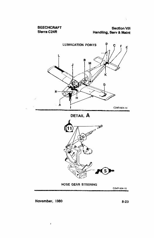
BEECHCRAFT Section VIIISierra C24R Handling, Serv & Maint
LUBRICATION POINTS D C F E
L
G
H
AI C24R-604-14
DETAIL A
o
NOSE GEAR STEERINGC24R 604-15
November, 1980 8-23
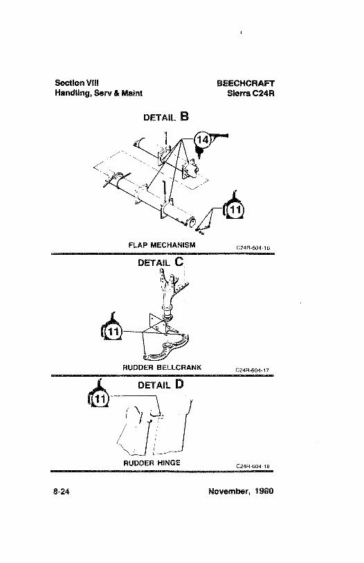
l
Section VIII BEECHCRAFTHandling, Serv & Maint Sierra C24R
DETAIL B
FLAP MECHANISM c24R-604-16
DETAIL Û
RUDDER BELLCRANK C24R-604-17
DETAIL D
RUDDER HINGE c24R-604-18
8-24 November, 1980
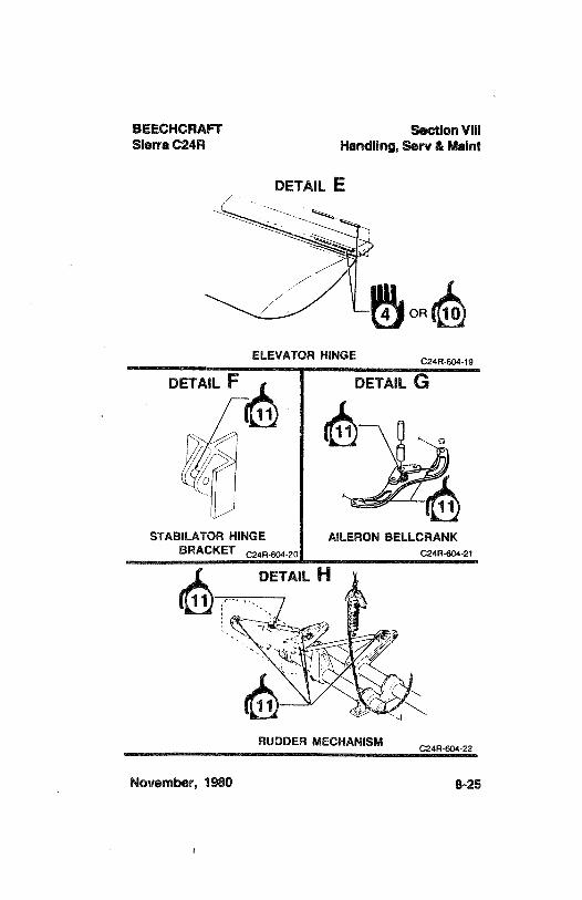
BEECHCRAFT Section VIIISierra C24R Handling, Serv & Maint
OR
ELEVATOR HINGE C24R-604-19
DETAIL F DETAIL G
STABILATOR HINGE AILERON BELLCRANKBRACKET C24R-604-20 C24R404-21
RUDDER MECHANISM C24R-604-22
November, 1980 8-25
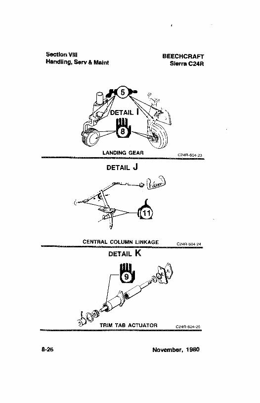
f
Section VIII BEECHCRAFTHandling, Serv & Maint Sierra C24R
LANDING GEAR C24R-604-23
DETAIL al
CENTRAL COLUMN LINKAGE C24R-604-24
DETAIL K
TRIM TAB ACTUATOR c24R-604-25
8-26 November, 1980
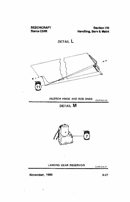
BEECHCRAFT Section VIIISierra C24R Handling, Serv & Maint
DETAIL L
AILERON HINGE AND ROD ENDSC24R 604 26
DETAIL M
LANDING GEAR RESERVOIRC24R 604-27
November, 1980 8-27
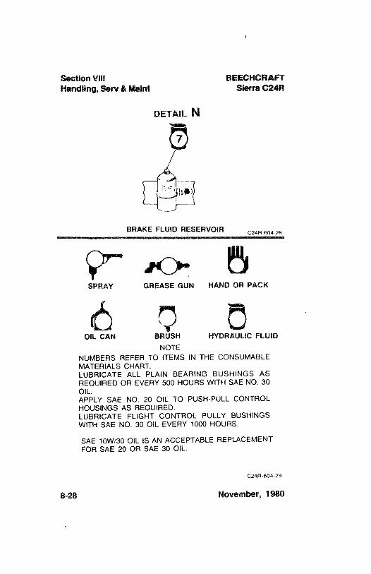
Section VIII BEECHCRAFTHandling, Serv & Maint Sierra C24R
DETAIL N
BRAKE FLUID RESERVOIR c24R-604 28
SPRAY GREASE GUN HAND OR PACK
OIL CAN BRUSH HYDRAULIC FLUIDNOTE
NUMBERS REFER TO ITEMS IN THE CONSUMABLEMATERIALS CHART.LUBRICATE ALL PLAIN BEARING BUSHINGS ASREQUIRED OR EVERY 500 HOURS WITH SAE NO. 30OIL.APPLY SAE NO. 20 OIL TO PUSH-PULL CONTROLHOUSINGS AS REQUIRED.LUBRICATE FLIGHT CONTROL PULLY BUSHINGSWITH SAE NO. 30 OIL EVERY 1000 HOURS.
SAE 10W/30 OIL IS AN ACCEPTABLE REPLACEMENTFOR SAE 20 OR SAE 30 OIL.
C24R-604-29
8-28 November, 1980
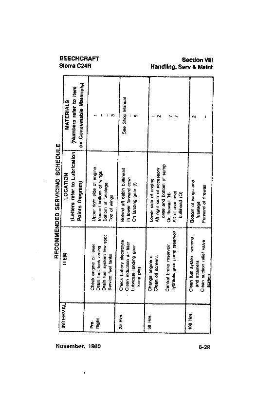
REC
OM
MEN
DED
SER
VIC
ING
SCH
EDU
LEEm
INTE
RV
AL
ITEM
LOC
ATI
ON
MA
TER
IALS
n(L
ette
rsre
fer
toLu
bric
atio
n(N
umbe
rsre
fer
toite
mPo
ints
Dia
gram
)on
Con
sum
able
Mat
eria
is)
Pre-
Che
cken
gine
oil
leve
lU
pper
right
side
ofen
gine
1m
fligh
tD
rain
fuel
tank
drai
nsIn
boar
dbo
ttom
ofw
ings
-
Dra
infu
elsy
stem
low
spot
Bot
tom
offu
sela
geSe
rvic
efu
elta
nks
Top
ofw
ings
3
25H
rs.
Che
ckba
ttery
elec
troly
teB
ehin
dat
t cab
inbu
lkhe
adSe
eSh
opM
anua
lC
lean
indu
ctio
nai
rfil
ter
inlo
wer
forw
ard
cow
lLu
bric
ate
land
ing
gear
On
land
ing
gear
(I)
5kn
eepi
ns
50H
rs.
Cha
nge
engi
neoi
lLo
wer
side
ofen
gine
1C
lean
oil
scre
ens
Aft
right
side
ofac
cess
ory
2ca
sean
dbo
ttom
ofsu
mp
Cen
tral
brak
ere
serv
oir
On
firew
all
(N)
7H
ydra
ulic
gear
pum
pre
serv
oir
Att
ofre
arse
at7
bulk
head
(0)
100
Mrs
.C
lean
tuel
syst
emsc
reen
sB
otto
mof
win
gsan
d2
and
stra
iner
sfu
sela
geo
Cle
ansu
ctio
nre
lief
valv
eFo
rwar
dof
firew
all
-
scre
en
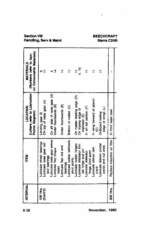
¿aIN
TER
VA
LIT
EMLO
CA
TIO
NM
ATE
RIA
LSe
(Let
ters
refe
rto
Lubr
icat
ion
(Num
bers
mfo
rto
item
Poin
tsD
iagr
am)
onC
onsu
mab
leM
ater
ials
)g
100
Hrs
.Lu
bric
ate
whe
elbe
arin
gsLa
ndin
gge
ar(I
)8
!!!
(Con
t'd)
Lubr
icat
eno
sege
arro
dO
nto
pof
nose
gear
(A)
11en
dbe
arin
gsLu
bric
ate
nose
gear
swiv
elO
naf
t sid
eof
nose
gear
(A)
5Lu
bric
ate
flap
torq
ueU
nder
floor
boar
ds(B
)14
tube
sLu
bric
ate
flap
rod
end
Und
erflo
orbo
ards
(B)
11be
arin
gsLu
bric
ate
rudd
erbe
llcra
nkB
otto
mof
rudd
er(C
)11
pivo
tpo
ints
Lubr
icat
eru
dder
hing
esO
nru
dder
lead
ing
edge
(D)
11Lu
bric
ate
stab
ilato
rtri
mO
ntra
iling
edge
of4,
10ta
bhi
nge
and
pin
stab
ilato
r(E
)Lu
bric
ate
stab
ilato
rin
aft
tail
sect
ion
(F)
11z
hing
epi
vot
poin
tLu
bric
ate
aile
ron
bell-
Inw
ing
forw
ard
ofai
lero
n11
cran
k(G
)Lu
bric
ate
aile
ron
pivo
tal
Out
boar
dtra
iling
11po
ints
and
rod
ends
edge
ofw
ings
(L)
e30
0H
rs.
Rep
lace
indu
ctio
nai
rfilt
erin
fron
tno
seco
wl
-
Io>
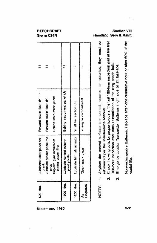
500
Hrs
.Lu
bric
ate
rudd
erpe
dal
bell-
Forw
ard
cabi
nflo
or(H
)11
cran
kp
niLu
bric
ate
rudd
erpe
dal
rod
Forw
ard
cabi
nflo
or(H
)11
men
dsR
epla
cegy
roin
stru
men
tB
ehin
din
stru
men
tpa
nel
-
cent
ral
pape
rfil
ter
m10
00H
rs.
Lubr
icat
eco
ntro
lco
lum
nB
ehin
din
stru
men
tpa
nel
(J)
11pi
vot
poin
ts
1200
Hrs
.Lu
bric
ate
trim
tab
actu
ator
Inaf
tta
ilse
ctio
n(K
)9
As
Cle
ansp
ark
plug
sin
engi
neco
mpa
rtmen
t-
Req
uire
d
NO
TES
1.A
nytim
eth
eco
ntro
lsu
rfac
esar
eal
tere
d,re
paire
d,or
repa
inte
d,th
eym
ust
bei
reba
lanc
edpe
rth
eM
aint
enan
ceM
anua
l.2.
Che
ckth
ew
ing
bolts
forp
rope
rto
rque
atth
efir
st10
0-ho
urin
spec
tion
and
atth
efir
st9
100-
hour
insp
ectio
naf
ter
each
rein
stal
latio
nof
the
win
gat
tach
bolts
.§
3.Em
erge
ncy
Loca
tor
Tran
smitt
erB
atte
ries
(rig
htsi
deof
aftf
usel
age)
:2
Non
-rec
harg
eabl
eB
atte
ries:
Rep
lace
afte
ron
ecu
mul
ativ
eho
uror
afte
r50
%of
the
usef
ullif
e.E
!!!!
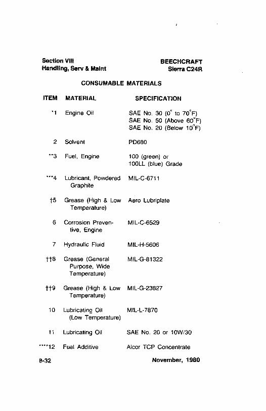
Section VIII BEECHCRAFTHandling, Serv & Maint Sierra C24R
CONSUMABLE MATERIALS
ITEM MATERIAL SPECIFICATION
*1 Engine Oil SAE No. 30(0° to 70°F)
SAE No. 50 (Above 60°F)
SAE No. 20 (Below 10°F)
2 Solvent PD680
**3 Fuel, Engine 100 (green)or100LL (blue) Grade
***4 Lubricant, Powdered MIL-C-6711Graphite
†5 Grease (High & Low Aero LubriplateTemperature)
6 Corrosion Preven- MIL-C-6529tive, Engine
7 Hydraulic Fluid MIL-H-5606
††8 Grease (General MIL-G-81322Purpose, WideTemperature)
††9 Grease (High & Low MIL-G-23827Temperature)
10 Lubricating Oil MIL-L-7870(Low Temperature)
11 Lubricating Oil SAE No. 20 or 10W/30
****12 Fuel Additive Alcor TCP Concentrate
8-32 November, 1980
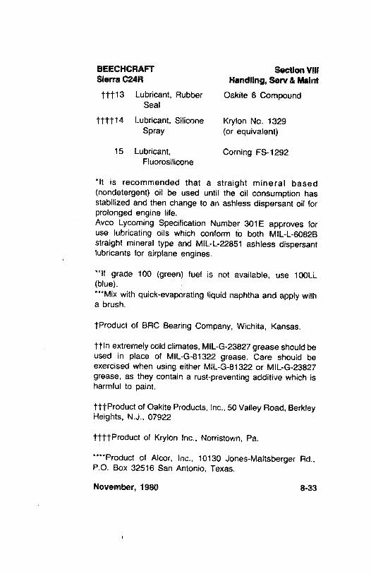
BEECHCRAFT Section VIIISierra C24R Handling, Serv & Maint
†††13 Lubricant, Rubber Oakite 6 CompoundSeal
††††14 Lubricant, Silicone Krylon No. 1329Spray (or equivalent)
15 Lubricant, Corning FS-1292Fluorosilicone
*lt is recommended that a straight mineral based(nondetergent) oil be used until the oil consumption hasstabilized and then change to an ashless dispersant oil forprolonged engine life.Avco Lycoming Specification Number 301E approves foruse lubricating oils which conform to both MIL-L-6082Bstraight mineral type and MIL-L-22851 ashless dispersantlubricants for airplane engines.
**If grade 100 (green)fuel is not available, use 100LL(blue).***Mixwith quick-evaporating liquid naphtha and apply witha brush.
†Product of BRC Bearing Company, Wichita, Kansas.
††ln extremely cold climates, MIL-G-23827 grease should beused in place of MIL-G-81322 grease. Care should beexercised when using either MIL-G-81322 or MIL-G-23827grease, as they contain a rust-preventing additive which isharmful to paint.
†††Product of Oakite Products, Inc., 50 Valley Road, BerkleyHeights, N.J., 07922
††††Product of Krylon Inc., Norristown, Pa.
****Product of Alcor, Inc., 10130 Jones-Maltsberger Rd.,P.O. Box 32516 San Antonio, Texas.
November, 1980 8-33
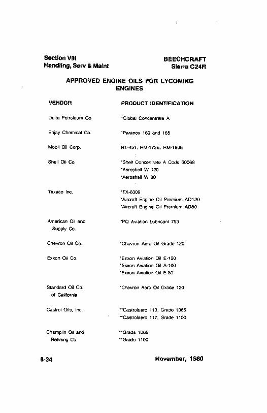
Section VIII BEECHCRAFTHandling, Serv & Maint Sierra C24R
APPROVED ENGINE OILS FOR LYCOMINGENGINES
VENDOR PRODUCT IDENTIFICATION
Delta Petroleum Co. "Global Concentrate A
Enjay Chemical Co. 'Paranox 160 and 165
Mobil Oil Corp. RT-451, RM-173E, RM-180E
Shell Oil Co. 'Shell Concentrate A Code 60068
'Aeroshell W 120°Aeroshell W 80
Texaco inc. *TX-6309
'Aircraft Engine Oil Premium AO120Aircraft Engine Oil Premium ADSO
American Oil and PQ Aviation Lubricant 753
Supply Co.
Chevron Oil Co. Chevron Aero Oil Grade 120
Exxon Oil Co. Exxon Aviation Oil E-120
Exxon Aviation Oil A-100
Exxon Aviation Oil E-80
Standard Oil Co. Chevron Aero Oil Grade 120
of California
Castrol Oils. Inc. Castrolaero 113, Grade 1065
Castrolaero 117, Grade 1100
Champlin Oil and Grade 1065
Refining Co. **Grade 1100
8-34 November, 1980
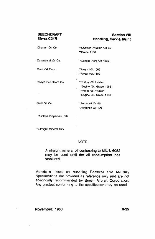
BEECHCRAFT Section VIIISierra C24R Handling, Serv & Maint
Chevron Oil Co. Chevron Aviation Oil 65Grade 1100
Continental Oil Co. * Conoco Aero Oil 1065
Mobil Oil Corp. **Avrex 101/1065**Avrex 101/1100
Phillips Petroleum Co. °°Phillips 66 AviationEngine Oil, Grade 1065
**Phillips 66 AviationEngine Oil, Grade 1100
Shell Oil Co. **Aeroshell Oil 65''Aeroshell Oil 100
'Ashless Dispersant Oils
**Straight Mineral Oils
NOTE
A straight mineral oil conformingto MIL-L-6082may be used until the oil consumption hasstabilized.
Vendors listed as meeting Federal and MilitarySpecifications are provided as reference only and are notspecifically recommended by Beech Aircraft Corporation.Any product conforming to the specification may be used.
November, 1980 8-35
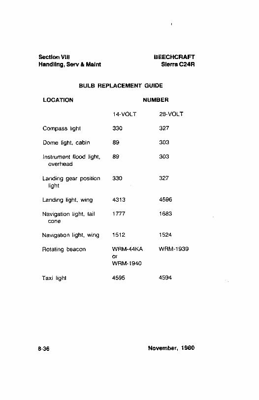
Section VIII BEECHCRAFTHandling, Serv & Maint Sierra C24R
BULB REPLACEMENT GUIDE
LOCATION NUMBER
14-VOLT 28-VOLT
Compass light 330 327
Dome light, cabin 89 303
instrument flood light, 89 303overhead
Landing gear position 330 327light
Landing light, wing 4313 4596
Navigation light, tail 1777 1683cone
Navigation light, wing 1512 1524
Rotating beacon WRM-44KA WRM-1939orWRM-1940
Taxi light 4595 4594
8-36 November, 1980
BEECHCRAFT Section VillSierra C24R Handling, Serv & Maint
OVERHAUL AND REPLACEMENT SCHEDULE
The first overhaul or replacement should be performed notlater than the required period. The conditionof the item atthe end of the first period can be used as a criterion fordetermining subsequent periods applicable to the individualairplane or fleet operation, providing the operator has anapproved monitoring system.
The time periods for inspections noted in this manual arebased on average usage and average environmentalconditions.
SPECIAL CONO/T/ONS CAUTIONARYNOT/CE
Airplanes operated for Air Taxi or other thannormal operation, and airplanes operated inhumid tropics or cold and damp climates, etc.,may need more frequent inspections for wear,corrosion and/or lack of lubrication. In theseareas periodic inspections should be performeduntil the operator can set his own inspectionperiods based on experience.
NOTE
The required periods do not constitute aguarantee the item will reach the period shownas the aforementioned factors cannot becontrolled by the manufacturer.
November, 1980 8-37
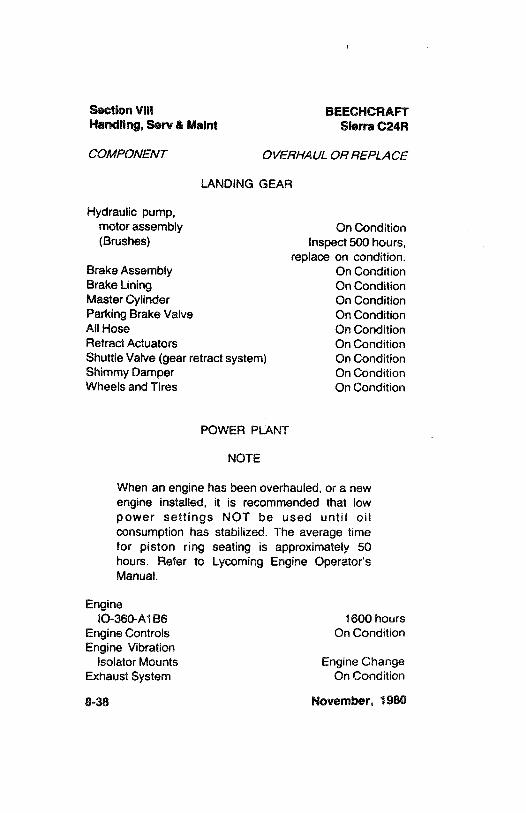
Section VIII BEECHCRAFTHandling, Serv & Maint Sierra C24R
COMPONENT OVERHAUL OR REPLACE
LANDING GEAR
Hydraulic pump,motorassembly On Condition(Brushes) Inspect 500 hours,
replace on condition.Brake Assembly On ConditionBrake Lining On ConditionMaster Cylinder On ConditionParking Brake Valve On ConditionAllHose On ConditionRetract Actuators On ConditionShuttle Valve (gearretract system) On ConditionShimmy Damper On ConditionWheels and Tires On Condition
POWER PLANT
NOTE
When an engine has been overhauled, or a newengine installed, it is recommended that lowpower settings NOT be used until oilconsumption has stabilized. The average timefor piston ring seating is approximately 50hours. Refer to Lycoming Engine Operator'sManual.
EnginelO-360-A1B6 1600 hours
Engine Controis On ConditionEngine Vibration
Isolator Mounts Engine ChangeExhaust System On Condition
8-38 November, 1980
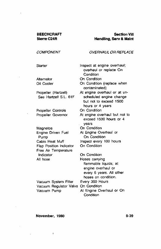
BEECHCRAFT Section VIIISierra C24R Handling, Serv & Maint
COMPONENT OVERHAUL OR REPLACE
Starter Inspect at engine overhaul;overhaul or replace OnCondition
Alternator On ConditionOil Cooler On Condition (replace when
contaminated)Propeller (Hartzell) At engine overhaul or at un-See Hartzell S.L. 61F scheduled engine change
but not to exceed 1500hours or 4 years
Propeller Controls On ConditionPropeller Governor At engine overhaul but not to
exceed 1500 hours or 4years
Magnetos On ConditionEngine Driven Fuel At Engine Overhaul or
Pump On ConditionCabin Heat Muff Inspect every 100 hoursFlap Position Indicator On ConditionFree Air Temperature
Indicator On ConditionAll hose Hoses carrying
flammable liquids; atengine overhaul orevery 5 years. AII otherhoses on condition.
Vacuum System Filter Every 300 HoursVacuum Regulator Valve On ConditionVacuum Pump At Engine Overhaul or On
Condition
November, 1980 8-39
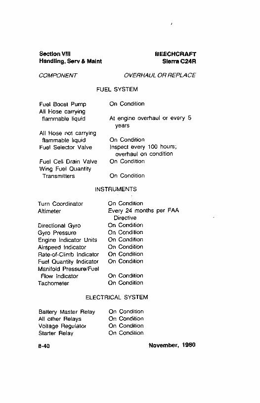
Section Vill BEECHCRAFTHandling, Serv & Maint Sierra C24R
COMPONENT OVERHAUL OR REPLACE
FUEL SYSTEM
Fuel Boost Pump On ConditionAll Hose carrying
flammable liquid At engirie overhaul or every 5years
All Hose not carryingflammable liquid On Condition
Fuel Selector Valve Inspect every 100 hours;overhaul on condition
Fuel Cell Drain Valve On ConditionWing Fuel Quantity
Transmitters On Condition
INSTRUMENTS
Turn Coordinator On ConditionAltimeter Every 24 months per FAA
DirectiveDirectional Gyro On ConditionGyro Pressure On ConditionEngine Indicator Units On ConditionAirspeed Indicator On ConditionRate-of-Climb Indicator On ConditionFuel Quantity Indicator On ConditionManifold Pressure/Fuel
Flow Indicator On ConditionTachometer On Condition
ELECTRICAL SYSTEM
Battery Master Relay On ConditionAll other Relays On ConditionVoltage Regulator On ConditionStarter Relay On Condition
8-40 November, 1980
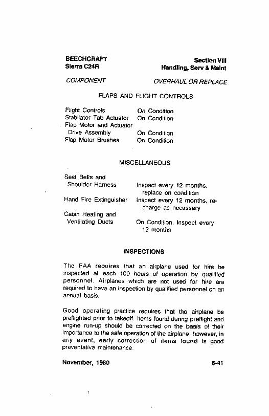
BEECHCRAFT Section VIIISierra C24R Handling, Serv & Maint
COMPONENT OVERHAUL OR REPLACE
FLAPS AND FLIGHT CONTROLS
Flight Controls On ConditionStabilator Tab Actuator On ConditionFlap Motor and ActuatorDrive Assembly On Condition
Flap Motor Brushes On Condition
MISCELLANEOUS
Seat Belts andShoulder Harness Inspect every 12 months,
replace on conditionHand Fire Extinguisher Inspect every 12 months, re-
charge as necessaryCabin Heating andVentilating Ducts On Condition, Inspect every
12 months
INSPECTIONS
The FAA requires that an airplane used for hire beinspected at each 100 hours of operation by qualifiedpersonnel. Airplanes which are not used for hire arerequired to have an inspection by qualified personnel on anannual basis.
Good operating practice requires that the airplane bepreflighted prior to takeoff. Items found during preftight andengine run-up should be corrected on the basis of theirimportance to the safe operation of the airplane; however, inany event, early correction of items found is goodpreventative maintenance.
November, 1980 8-41
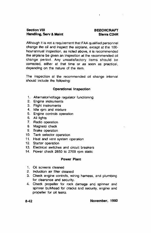
Section VIII BEECHCRAFTHandling, Serv & Maint Sierra C24R
Although it is not a requirement that FAA qualified personnelchange the oil and inspect the airplane, except at the 100-hourlannual inspection, as noted above, it is recommendedthe airplane be given an inspection at the recommended oilchange period. Any unsatisfactory items should becorrected, either at that time or as soon as practical,depending on the nature of the item.
The inspection at the recommended oil change intervalshould include the following:
Operational inspection
1. Alternator/voltage regulator functioning2. Engine instruments3. Flight instruments4. Idle rpm and mixture5. Engine controls operation6. All lights7. Radio operation8. Magneto check9. Brake operation
10. Tank selector operation11. Heat and vent system operation12. Starter operation13. Electrical switches and circuit breakers14. Power check 2650 to 2700 rpm static
Power Plant
1. Oil screens cleaned2. Induction air filter cleaned3. Check engine controls, wiring harness, and plumbing
for clearance and security.4. Check propeller for rock damage and spinner and
spinner bulkhead for cracks and security, engine andpropeller for oil leaks.
8-42 November, 1980
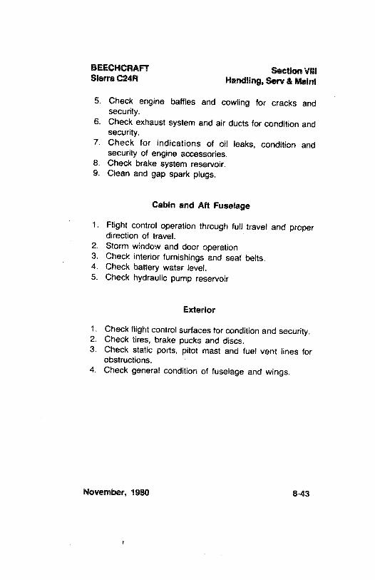
BEECHCRAFT Section VIIISierra C24R Handling, Serv & Maint
5. Check engine baffles and cowling for cracks andsecurity.
6. Check exhaust system and air ducts for condition andsecurity.
7. Check for indications of oil leaks, condition andsecurity of engine accessories.
8. Check brake system reservoir.9. Clean and gap spark plugs.
Cabin and Aft Fuselage
1. Flight control operation through full travel and properdirection of travel.
2. Storm window and door operation3. Check interior furnishings and seat belts.4. Check battery water level.5. Check hydraulic pump reservoir
Exterior
1. Check flight controlsurfaces for condition and security.2. Check tires, brake pucks and discs.3. Check static ports, pitot mast and fuel vent lines for
obstructions.4. Check general condition of fuselage and wings.
November, 1980 8-43

$
BEECHCRAFTSierra C24R
SECTION IX
SUPPLEMENTS
NOTE
The supplemental data contained in this sectionis for equipment that was delivered on theairplane, and for standard optional equipmentthat was available whether or not it wasinstalled. Supplements for equipment for whichthe vendor obtained a Supplemental TypeCertificate were included as loose equipmentwith the airplane at the time of delivery. Theseand other Supplements for other equipment thatwas installed after the airplane was deliverednew from the factory should be placed in thisSUPPLEMENTS Section of this Pilot'sOperating Handbook and FAA ApprovedAirplane Flight Manual.
November, 1980 9-1
Section IX BEECHCRAFTSupplements Sierra C24R
INTENTIONALLY LEFT BLANK
9-2 November, 1980
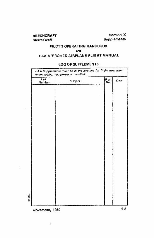
BEECHCRAFT Section IXSierra C24R Supplements
PILOT'S OPERATING HANDBOOKand
FAA APPROVED AIRPLANE FLIGHT MANUAL
LOG OF SUPPLEMENTS
FAA Supplements must be in the airplane for flight operationwhen subject equipment is installed:
Nu ber Subject e Date
November, 1980 9-3

l
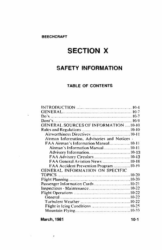
BEECHCRAFT
SECTION X
SAFETY INFORMATION
TABLE OF CONTENTS
INTRODUCTION ................ ..................
10-4GENERAL.................. .................
10-7Do's ................... .................
10-7Dont's...................... ..................................
10-9GENERAL SOURCES OF INFORMATION ....10-10
Rules and Regulations ...................................10-10
Airworthiness Directives ............................10-11
Airman Information, Advisories and Notices -
FAA Airman's Information Manual...............10-11Airman's Information Manual...................10-11Advisory Information..............................10-13FAA Advisory Circulars..........................10-13FAA General Aviation News ....................10-18
FAA Accident Prevention Program............10-19GENERAL INFORMATION ON SPECIFICTOPICS................. ...................10-20
Flight Planning.................. .................10-20
Passenger Information Cards ..........................10-21
Inspections - Maintenance..............................10-22Flight Operations ................
.................10-22
General................. ..................10-22
Turbulent Weather ................ .
.................10-22
Flight in Icing Conditions ............................10-25
Mountain Flying.................. .................10-33
March, 1981 10-1
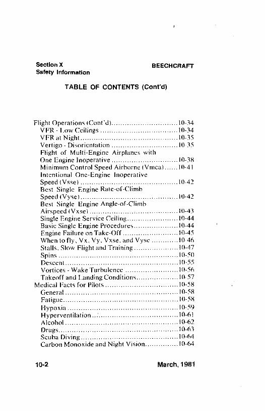
Section X BEECHCRAFTSafety information
TABLE OF CONTENTS (Cont'd)
Flight Operations (Cont'd)..............................10-34VFR - Low Ceilings ...............
................10-34
VFR at Night................. .................10-35
Vertigo - Disorientation ..............................10-35
Flight of Multi-Engine Airplanes withOne Engine Inoperative ..............................10-38
Minimum Control Speed Airborne (Vmca)......10-41Intentional One-Engine InoperativeSpeed (Vsse) ............................................10-42
Best Single Engine Rate-of-ClimbSpeed (Vyse)......................... ..................10-42
Best Single Engine Angle-of-ClimbAirspeed (Vxse)................. ................10-43
Single Engine Service Ceiling.......................10-44Basic Single Engine Procedures....................10-44Engine Failure on Take-Off .........................10-45
When to fly, Vx, Vy, Vxse, and Vyse ............10-46
Stalls, Slow Flight and Training ....................10-47
Spins ................ .
.................10-50
Descent................. ... ....
................10-55
Vortices - Wake Turbulence ........................10-56
Takeoff and Landing Conditions...................10-57Medical Facts for Pilots.................................10-58
General.............. .
................10-58
Fatigue................ .................10-58
Hypoxia ................
................10-59
Hyperventilation................. ................10-61
Alcohol ............... .
...............10-62
Drugs................ .
...............10-63
Scuba Diving....................... ....................10-64
Carbon Monoxide and Night Vision...............10-64
10-2 March, 1981
BEECHCRAFT Section XSafety Information
TABLE OF CONTENTS (Cont'd)
ADDITIONAL INFORMATION....................10-64Special Conditions................. .
...................10-66
Maintenance .................
..................10-66
March, 1981 10-3
Section X BEECHCRAFTSafety information
INTRODUCTION
The best engineering and manufacturingcraftsmanship have gone into the design and buildingof all BEECHCRAFTS. Like any other highperformance airplane, they operate efficiently andsafely only in the hands of a skilled pilot.
You must be thoroughly familiar with the contentsof your operating manuals, placards, and check liststo insure safe utilization of your airplane. When theairplane was manufactured, it was equipped with
one or more of the following: placards, OwnersManual, FAA Flight Manual, Pilots OperatingHandbook and FAA Approved Flight Manual. Forsimplicity and convenience we will refer to allofficial manuals in various models as the"Information Manual". If the airplane has changedownership, the Information Manual may have beenmisplaced or may not be current. If missing or outof date, replacement Information Manuals must beobtained from any BEECHCRAFT Aviation Centeras soon as possible.
For your added protection and safety, we havedeveloped this special publication of safetyinformation to refresh owners' and pilots' knowledgeof a number of safety subjects. These subjects must
10-4 March, 1981
BEECHCRAFT Section XSafety Information
be reviewed periodically and kept with the airplane,along with the Information Manual and otherdocuments required for operation of the airplane.
Topics in this publication are dealt with in moredetail in FAA Documents and other articlespertaining to the subject of safe flying. The safepilot is familiar with this literature.
BEECHCRAFT airplanes are designed and built toprovide owners and pilots with many years of safeand efficient transportation. By maintaining itproperly and flying it prudently, you will realize itsfull potential.
WARNING
Because your aircraft is a highperformance, high speed transportationvehicle, designed for operation in a three-
dimensional environment, special safetyprecautions must be observed to reducethe risk of fatal or serious injuries to thepilot(s) and occupant(s).
It is mandatory that you fully understand thecontents of this manual and the other operating andmaintenance manuals which accompany the aircraft;
March, 1981 10-5
i
Section X BEECHCRAFTSafety Information
that FAA requirements for ratings, certifications andreview be scrupulously complied with; and that youallow only persons who are properly licensed andrated, and thoroughly familiar with the contents ofthe Information Manual, to operate the aircraft.IMPROPER OPERATION OR MAINTENANCEOF AN AIRCRAFT, NO MATTER HOW WELLBUILT INITIALLY, CAN RESULT INCONSIDERABLE DAMAGE OR TOTAL
DESTRUCTION OF THE AIRCRAFT ALONGWITH SERIOUS OR FATAL INJURIES TO ALL
OCCUPANTS.
. . .BEECH AIRCRAFT CORPORATION
10-6 March, 1981
BEECHCRAFT Section XSafety information
GENERAL
As a pilot, you are responsible to yourself and tothose who fly with you, to other pilots and theirpassengers, and to people on the ground, to flywisely and safely.
The following material in this Safety Section coversseveral subjects in limited detail. Here are somecondensed Do's and Don'ts.
DO'S
Be thoroughly familiar with your airplane, know itslimitations and your own.
Be current in your airplane, or fly with a qualifiedinstructor until you are current/proficient.
Pre-plan all aspects of your flight - including weatherand adequate fuel reserves.
Use services available - Weather briefing, in-flightweather and Flight Service Station.
Carefully pre-flight your airplane.
Use the approved check list.
March, 1981 10-7
Section X BEECHCRAFTSafety information
Have more than enough fuel for takeoff, plus thetrip, and an adequate reserve.
Be sure your weight loading and C.G. are within
limits.
Pilot(s) and passengers must use seat belts andshoulder harnesses at all times.
Be sure all loose articles and baggage are secured.
Check freedom of all controls during pre-flight
inspection and before takeoff.
Maintain the prescribed airspeeds in takeoff, climb,descent and landing.
Avoid big airplane wake turbulence.
Preplan fuel and fuel tank management before theactual flight. Utilize auxiliary tanks only in levelcruise flight. Take off and land on the fullest maintank.
Practice emergency procedures at safe altitudes andairspeeds, preferably with a qualified instructorpilot, until the required action is instinctive.
Keep your airplane in good mechanical condition.
10-8 March, 1981
BEECHCRAFT Section XSafety information
Stay informed and alert; fly in a sensible manner.
DON'TS
Don't take off with frost, ice or snow on theairplane.
Don't take off with less than minimumrecommended fuel, plus adequate reserves, anddon't run the tank dry before switching.
Don't fly in a reckless, show-off, careless manner.
Don't fly into thunderstorms or severe weather.
Don't fly in possible icing conditions unless theairplane is approved and properly equipped.
Don't fly close to mountainous terrain.
Don't apply controls abruptly or with high forcesthat could exceed design loads of the airplane.
Don't fly into weather conditions that are beyondyour ratings or current proficiency.
Don't attempt any take off or landing without usingthe check list.
March, 1981 10-9
Section X BEECHCRAFTSafety Information
Don't fly when physically or mentally exhausted or
below par.
Don't trust to luck.
GENERAL SOURCES OF INFORMATION
There is a wealth of information available to thepilot created for the sole purpose of making yourflying safer, easier and faster. Take advantage ofthis knowledge and be prepared for an emergency inthe remote event that one should occur.
You, as a pilot, have responsibilities undergovernment regulations. These are designed for yourprotection and the protection of your passengers.Compliance is mandatory.
RULES AND REGULATIONS
F.A.R. Part 91, General Operating and Flight Rules,is a document of law governing operation of aircraftand the owner's and pilot's responsibilities. Thisdocument covers such subjects as:
Responsibilities and authority of the pilot-in-
command
10-10 March, 1981
BEECHCRAFT Section XSafety Information
Certificates requiredLiquor and drugsFlight plansPre-flight actionFuel requirementsFlight rulesMaintenance, preventative maintenance,alterations, inspection, and maintenance records
These are only some of the topics covered. It is theowner's and pilot's responsibility to be thoroughlyfamiliar with all items in F.A.R. Part 91 and tofollow them.
A/RWORTHINESSD/RECT/VES
F.A.R. Part 39 specifies that no person may operatea product to which an airworthiness directive issuedby the FAA applies, except in accordance with therequirements of that airworthiness directive.
A/RMAN /NFORMATION, ADVISOR/ES, ANDNOTICES - FAA A/RMAN'S /NFORMATIONMANUAL
AIRMAN'S INFORMATION MANUAL
The Airman's Information Manual (AIM) is designed
March, 1981 10-11
i
Section X BEECHCRAFTSafety Information
to provide airmen with basic flight information andATC procedures for use in the national airspacesystem of the United States. It also contains itemsof interest to pilots concerning health and medicalfacts, factors affecting flight safety, apilot/controller glossary of terms used in the AirTraffic Control System, information on safety, andaccident and hazard reporting. It is revised at six-
month intervals and can be purchased locally orfrom the Superintendent of Documents, U. S.Government Printing Office, Washington, D. C.20402.
This document contains a wealth of pilotinformation. Among the subjects are:
Controlled Air SpaceServices Available to PilotsRadio Phraseology and TechniqueAirport OperationsClearances and SeparationsPre-flightDepartures - IFREnroute - IFRArrival - IFREmergency ProceduresWeather and IcingMountain FlyingWake Turbulence - Vortices
10-12 March, 1981
BEECHCRAFT Section XSafety information
Medical Facts for PilotsBird HazardsGood Operating PracticesAirport Location Directory
All pilots must be thoroughly familiar with and use
the information in the AIM.
ADVISORY INFORMATION
NOTAMS (Notices to Airmen) are documents thathave information of a time-critical nature that wouldaffect a pilot's decision to make a flight; forexample, an airport closed, terminal radar out ofservice, enroute navigational aids out of service, etc.
Airmen can subscribe to services to obtain FAANOTAMS and Airman Advisories, and these arealso available at FAA Flight Service Stations.
FAA ADVISORY CIRCULARS
The FAA issues advisory circulars to inform theaviation public in a systematic way of non-regulatorymaterial of interest. Advisory Circulars contain awealth of information with which the prudent pilotshould be familiar. A complete list of current FAAadvisory circulars is published in Advisory Circular
March, 1981 10-13
Section X BEECHCRAFTSafety information
AC00-2, which lists advisory circulars that are forsale, as well as those distributed free of charge bythe FAA, and provides ordering information. Manyadvisory circulars which are for sale can bepurchased locally in aviation bookstores or atFBO's. Some of the advisory circulars of interest to
pilots are:
* 00-6A Aviation Weather00-24 Thunderstorms00-30 Rules of Thumb for Avoiding or
Minimizing Encounters with ClearAir Turbulence
* 00-45A Aviation Weather Services00-46A Aviation Safety Reporting Program00-50 Low Level Wind Shear20-5D Plane Sense20-93 Flutter Due to Ice or Foreign
Substance on or in Aircraft Control
Surfaces20-105 Engine Power-Loss Accident
Prevention39-7 Airworthiness Directives for General
Aviation Aircraft43-12 Preventive Maintenance60-4 Pilot's Spatial Disorientation
10-14 March, 1981
BEECHCRAFT Section XSafety Information
60-6A Airplane Flight Manuals (AFM),Approved Manual Materials,Markings and Placards - Airplanes
60-9 Induction Icing - Pilot Precautionsand Procedures
60-12 Availability of Industry-DevelopedGuidelines for the Conduct of theBiennial Flight Review
60-13 The Accident Prevention CounselorProgram
* 61-8D Instrument Rating Written TestGuide
61-9B Pilot Transition Courses forComplex Single-Engine and Light,Twin Engine Airplanes
* 61-10A Private and Commercial PilotsRefresher Courses
61-12J Student Pilot Guide61-19 Safety Hazard Associated with
Simulated Instrument Flights* 61-21 Flight Training Handbook* 61-23A Pilot's Handbook of Aeronautical
Knowledge* 61-27B Instrument Flying Handbook* 61-32B Private Pilot - Airplane - Written
Test Guide* 61-348 Federal Aviation Regulations
Written Test Guide for Private,Commercial and Military Pilots
March, 1981 10-15
Section X BEECHCRAFTSafety Information
61-47 Use of Approach Slope Indicatorsfor Pilot Training
* 61-54A Private Pilot Airplane - Flight TestGuide
* 61-55A Commercial Pilot Airplane . .
Flight Test Guide* 61-56A Flight Test Guide - Instrument Pilot
Airplane* 61-58 Flight Instructor Practical Test
Guide61-65 Part 61 (Revised) Certification Pilot
and Flight Instructors61-67 Hazards Associated with Spins in
Airplanes Prohibited fromIntentional Spinning
* 61-70 Flight Instructor Instrument -
Airplane - Written Test Guide* 61-71A Commercial Pilot Airplane Written
Test Guide* 61-72A Flight instructor - Airplane Written
Test Guide61-84 Role of Preflight Preparation
* 67-2 Medical Handbook for Pilots90-23D Wake Turbulence90-34 Accidents resulting from
Wheelbarrowing in Tricycle GearEquipped Aircraft
10-16 March, 1981
BEECHCRAFT Section XSafety Information
90-42A Traffic Advisory Practices at Non-
tower airports90-43D Operations Reservation for High-
Density Traffic Airports90-48 Pilots' role in Collision Avoidance90-64 Automated Radar Terminal System
(ARTS) III90-66 Recommended Standard Traffic
Patterns for Airplane Operations atUncontrolled Airports
91-6A Water, Slush and Snow on runway91-8A Use of Oxygen by General Aviation
Pilots/Passengers91-11B Annual Inspection Reminder91-13C Cold Weather Operation of Aircraft91-17 The use of View Limiting Devices
on Aircraft* 91-23A Pilot's Weight and Balance
Handbook91-24 Aircraft Hydroplaning or
Aquaplaning on Wet Runways91-25A Loss of Visual Cues During Low
Visibility Landings91-28 Unexpected Opening of Cabin Doors
March, 1981 10-17
i
Section X BEECHCRAFTSafety Information
91-33 Use of Alternate Grades of AviationGasoline for Grade 80/87
91-35 Noise, Hearing Damage, and Fatiguein General Aviation Pilots
91-43 Unreliable Airspeed Indications91-46 Gyroscopic Instruments - Good
Operating Practices91-51 Airplanes Deice and Anti-Ice
Systems103-4 Hazard Associated with Sublimation
of Solid Carbon Dioxide (Dry Ice)Aboard Aircraft
150/5200-3A Bird Hazards to Aircraft210-lA National Notice to Airmen System210-5 Military Flying Activities
* Advisory Circulars that are for sale.
FAA GENERAL AVIATION NEWS
FAA General Aviation News is published by theFAA in the interest of flight safety. The magazine isdesigned to promote safety in the air by calling theattention of general aviation airmen to currenttechnical, regulatory and procedural mattersaffecting the safe operation of aircraft. FAA GeneralAviation News is sold on subscription by the
10-18 March, 1981
BEECHCRAFT Section XSafety Information
Superintendent of Documents, Government PrintingOffice, Washington, D. C. 20402.
FAA ACCIDENT PREVENTION PROGRAM
The FAA assigns accident prevention specialists toeach Flight Standards and General Aviation DistrictOffice to organize accident prevention programactivities. In addition, there are over 3,000 volunteerairmen serving as accident prevention counselors,sharing their technical expertise and professionalknowledge with the general aviation community. TheFAA conducts seminars and workshops, anddistributes invaluable safety information under thisprogram.
Usually the airport manager, the FAA Flight ServiceStations (FSS), or Fixed Base Operator (F.B.O.),will have a list of accident prevention counselorsand their phone numbers available. All FlightStandards and General Aviation District Officeshave a list of the counselors serving the district.
Before flying over unfamiliar territory, such asmountainous terçain or desert areas, it is advisablefor transient pilots to consult with local counselors.They will be familiar with the more desirable routes,the wind and weather conditions, and the serviceand emergency landing areas that are available along
March, 1981 10-19
Section X BEECHCRAFTSafety Information
the way. They can also offer advice on the type ofemergency equipment you should be carrying.
GENERAL INFORMATION ON SPECIFICTOPICS
FLIGHT PLANNING
F.A.R. Part 91 requires that each pilot in command,before beginning a flight, familiarize himself with allavailable information concerning that flight.
Obtain a current and complete pre-flight briefing.This should consist of local, enroute and destinationweather and enroute navaid information. Enrouteterrain and obstructions, alternate airports, airportrunways active, length of runways, and take-off andlanding distances for the airplane for conditionsexpected should be known.
The prudent pilot will review his planned enroutetrack and stations and make a list for quickreference. It is strongly recommended a flight planbe filed with Flight Service Stations, even thoughthe flight may be VFR. Also, advise Flight ServiceStations of changes or delays of one hour or moreand remember to close the flight plan at destination.
10-20 March, 1981
BEECHCRAFT Section XSafety information
The pilot must be completely familiar with theperformance of the airplane and performance data inthe Information Manual. The resultant effect oftemperature and pressure altitude must be taken intoaccount in determining performance if not accountedfor on the charts. An applicable FAA ApprovedFlight Manual, if one is provided, must be aboardthe airplane at all times including the weight andbalance forms and equipment list.
PASSENGER INFORMATION CARDS
Beech has available, for most current productionairplanes, passenger information cards which containimportant information on the proper use of restraintsystems, oxygen masks, emergency exits andemergency bracing procedures. Passengerinformation cards may be obtained at anyBeechcraft Aviation or Aero Center. A pilot shouldnot only be familiar with the information containedin the cards himself, but should, prior to flight,always inform passengers of the informationcontained in the information cards. If a passengerinformation card is not available for your model ofairplane, the pilot should orally brief the passengerson the proper use of restraint systems, doors andemergency exits, and other emergency procedures,as required by Part 91 of the FAR's.
March, 1981 10-21
1
Section X BEECHCRAFTSafety Information
INSPECTIONS - MAINTENANCE
In addition to maintenance inspections and pre-flight
information required by F.A.R. Part 91, a completepre-flight inspection is imperative. It is theresponsibility of the owner and the operator toassure that the airplane is maintained in an airworthycondition and that proper maintenance records arekept.
Each airplane has a checklist for the pre-flight
inspection which must be followed. USE THECHECKLIST!
FLIGHT OPERATIONS
GENERAL
The pilot must be thoroughly familiar with allinformation published by the manufacturerconcerning the airplane, and in required by law tooperate the airplane in accordance with the FA AApproved Airplane Flight Manual and/or placards
installed.
TURBULENT WEATHER
A complete and current weather briefing is a
requirement for a safe trip.
10-22 March, 1981
BEECHCRAFT Section XSafety information
Updating of weather information enroute is alsoessential. The wise pilot knows that weather
conditions can change quickly, and treats weather
forecasting as professional advice, rather than anabsolute fact. He obtains all the advice he can, butstays alert to any sign or report of changingconditions.
Plan the flight to avoid areas of severe turbulenceand thunderstorms. It is not always possible todetect individual storm areas or find the in-betweenclear areas.
Thunderstorms, squall lines and violent turbulenceshould be regarded as extremely dangerous and mustbe avoided. Hail and tornadic wind velocities can beencountered in thunderstorms that can destroy anyairplane, just as tornadoes destroy nearly everythingin their path on the ground.
Turboprop Engines - Thunderstorms also pose thepossibility of a lightning strike on an aircraft. Anystructure or equipment which shows evidence of a
lightning strike, or of being subjected to a highcurrent flow due to a strike, or is a suspected part ofa lightning strike path through the aircraft, should bethoroughly inspected and any damage repaired priorto additional flight. The Pratt & Whitney or
March, 1981 10-23
Section X BEECHCRAFTSafety Information
AiResearch Engine Maintenance Manual andHartzell Service Letter No. 104 include inspectionand maintenance requirements for engines andpropellers involved in lightning strike incidents.
A roll cloud ahead of a squall line or thunderstorm isvisible evidence of violent turbulence; however, theabsence of a roll cloud should not be interpreted asdenoting that severe turbulence is not present.
Even though flight in severe turbulence must beavoided, flight in turbulent air may be encounteredunexpectedly under certain conditions.
The following recommendations should be observedfor airplane operation in turbulent air:
Flying through turbulent air presents two basicproblems, the answer to both of which is properairspeed. On one hand, if you maintain an excessiveairspeed, you run the risk of structural damage orfailure: on the other hand, if your airspeed is toolow, you may stall.
If turbulence is encountered, reduce speed to theturbulent air penetration speed, if given, or to themaneuvering speed, which is listed in theLimitations Section of the Information Manual.These speeds give the best assurance of avoiding
10-24 March, 1981
BEECHCRAFT Section XSafety Information
excessive stress loads, and at the same timeproviding the proper margin against inadvertentstalls due to gusts.
Beware of overcontrolling in attempting to correctfor changes in attitude; applying control pressure
abruptly will build up G-forces rapidly and couldcause structural damage or even failure. You shouldwatch particularly your angle of bank, making turnsas wide and shallow as possible. Be equally cautiousin applying forward or back pressure to keep thenose level. Maintain straight and level attitude ineither up or down drafts. Use trim sparingly to avoidbeing grossly out of trim as the vertical air columnschange velocity and direction. If necessary to avoidexcessive airspeeds, lower the landing gear.
FL/GHT /N /C/NG COND/TIONS
Every pilot of Beech airplanes (for that matter thepilot of any airplane) should be intimatelyacquainted with the FAA Approved NationalWeather Service definitions for ice intensity andaccumulation which we have reprinted below:
INTENSITY ICE ACCUMULATION
Trace Ice becomes perceptible. Rate ofaccumulation slightly greater than rate
March, 1981 10-25
Section X BEECHCRAFTSafety information
INTENSITY ICE ACCUMULATION (Cont'd)
Trace of sublimation. It is not hazardous even(Cont'd) though deicing/anti-icing equipment is
not utilized, unless encountered for anextended period of time (over 1 hour).
Light The rate of accumulation may create a
problem if flight is prolonged in thisenvironment (over 1 hour). Occasionaluse of deicinglanti-icing equipmentremoves/prevents accumulation. It doesnot present a problem if thedeicing/anti-icing equipment is used.
Moderate The rate of accumulation is such thateven short eticounters becomepotentially hazardous and use ofdeicing/anti-icing equipment ordiversion is necessary.
Severe The rate of accumulation is such thatdeicinglanti-icing equipment fails toreduce or control the hazard.Immediate diversion is necessary.
It is no longer unusual to find deicing and anti-icingequipment on a wide range of airplane sizes and
10-26 March, 1981
BEECHCRAFT SectionXSafety Information
types. Since the capability of this equipment varies,
it becomes the pilot's primary responsibility to
understand limitations which restrict the use of hisairplane in icing conditions and the conditions which
may exceed the systems capacity.
Pilots and airplane owners must carefully review theInformation Manual in order to ascertain therequired operable equipment needed for flight inicing conditions. In addition, they must ascertain
from the same sources the limits of approval orcertification of their airplane for flight in icingconditions, and plan the flight accordingly, if icingconditions are known or forecast along the route.
Every owner and pilot of an airplane shouldunderstand that it is not uncommon to find aircraftequipped with less than the full complement ofavailable systems and equipment. For example,props and pitot tube may be protected, but theaircraft might not have wing boots or tail boots. Thereverse might be true. Windshield, pitot and airfoilsurfaces might be protected, but the props might notbe. Before undertaking any flight into areas where
icing conditions might be suspected, inspect theaircraft and review the Information Manual to becertain that you are supported by the fullcomplement of required IFR and deicinglanti-icingeqwpment.
March, 1981 10-27
Section X BEECHCRAFTSafety information
Remember that regardless of its combination ofdeicinglanti-icing equipment, any aircraft not fullyequipped and functional for IFR flight is notproperly equipped for flight in icing conditions.
An airplane which is not approved or certificated forflight in icing conditions, not fully equipped, orwhich does not have all critical areas protected inthe required manner by fully operational equipmentmust not be exposed to icing encounters of anyintensity. When icing is detected, the pilot of suchan aircraft must make an immediate diversion byflying out of the area of visible moisture or going toan altitude where icing is not encountered.
Some models of Beech airplanes were approved forflight in certain limited icing conditions under theFAA's Bureau of Flight Standards Release No. 434.Under this release, properly equipped airplanes areapproved for flight in light to moderate icingconditions only. These aircraft are not approved forextended flight in moderate icing conditions orflights in any severe icing conditions. Flight in theseconditions must be avoided.
Even airplanes fully equipped and certified for flightin the icing conditions described in Appendix C toFAR Part 25 must avoid flights into those conditionsdefined by the National Weather Service as
10-28 March, 1981
BEECHCRAFT Section XSafety information
"Severe". The National Weather Service definitionof "severe icing" describes that condition as: "therate of accumulation is such that deicinglanti-icingequipment fails to reduce or control the hazard." Noairplane equipped with any combination ofdeicing/anti-icing equipment can be expected to copewith such conditiohs. As competent pilots know,there appear to be no predictable limits for theseverest weather conditions. For essentially thesame reasons that airplanes, however designed orequipped for IFR flight, cannot be flown safely intoconditions such as thunderstorms, tornados,hurricanes or other phenomena likely to producesevere turbulence, airplanes equipped for flight inicing conditions cannot be expected to cope with
"severe" icing conditions as defined by the NationalWeather Service. The prudent pilot must remainalert to the possiblity that icing conditions maybecome "severe", and that his equipment will notcope with them. At the first indication that suchcondition may have been encountered or may lieahead, he should immediately react by selecting themost expeditious and safe course for diversion.
Every pilot of a properly and fully-equipped Beechairplane who ventures into icing conditions mustmaintain the minimum speed (KIAS) for operation inicing conditions, which is set forth in the NormalProcedures Section of his Information Manual. If a
March, 1981 10-29
Section X BEECHCRAFTSafety Information
minimum speed for flight in icing conditions is notspecified in the manual, the following indicatedairspeeds must be maintained:
All Baron and Travel Air Models - 130 KIAS
All other Beechcraft twin-engine models - 140 KIAS
The pilot must remain aware of the fact that if heallows his airspeed to deteriorate below thisminimum speed, he will increase the angle of attack
of his airplane to the point where ice may build upon the under side of the wings aft of the areaprotected by the boots.
The fact or extent of ice build-up in unprotected
areas will not be directly observable from thecockpit. Due to distortion of the wing airfoil,increased drag and reduced lift, stalling speeds will
increase as ice accumulates on the airplane. For thesame reasons, stall warning devices are not accurate
and cannot be relied upon in icing conditions.
Even though the pilot maintains the prescribedminimum speed for operating in icing conditions, iceis still likely to build up on other unprotected areas
(the fuselage and the unprotected wing leading edgeinboard of the engine nacelle). Under some
atmospheric conditions, it may even build up aft of
10-30 March, 1981
BEECHCRAFT Section XSafety Information
the boots despite the maintenance of the prescribedminimum speed. The effect of ice accumulation on
any unprotected surface is aggravated by the lengthof exposure to the icing conditions. Ice buildup onunprotected surfaces will increase drag, add weight,reduce lift, and generally, adversely affect theaerodynamic characteristics and performance of theairplane. It can progress to the point where theairplane is no longer capable of flying. Therefore,the pilot operating even a fully-equipped airplane insustained icing conditions must remain sensitive toany indication, such as observed ice accumulation,loss of airspeed, the need for increased power,reduced rate of climb, or sluggish response, that iceis accumulating on unprotected surfaces and thatcontinued flight in these conditions is éxtremelyhazardous, regardless of the performance of thedeieinglanti-icing equipment.
Rapid cycling of the deice boots or cycling before atleast one-quarter inch (1/4") of ice has accumulated(measured in the chordwise direction or forwardfrom the leading edge), may cause the ice to growoutside the contour of the inflated boots and preventice removat
March, 1981 10-31
Section X BEECHCRAFTSafety Information
For any owner or pilot whose use pattern for anaircraft exposes it to icing encounters, the followingreferences are required reading for safe flying:
The aircraft's Information Manual, expecially thesections on Normal Procedures, EmergencyProcedures, Systems, and Safety Information.
FAA Advisory Circular 91-51 - Airplane Deiceand Anti-ice Systems.
Weather Flying, by Robert N. Buck.
Finally, the most important ingredients to safe flightin icing conditions - regardless of the aircraft or thecombination of deicing/anti-icing equipment - are acomplete and current weather briefing, sound pilotjudgment, close attention to the rate and type of iceaccumulations, and the knowledge that "severeicing" as defined by the National Weather Service isbeyond the capability of modern aircraft andimmediate diversion must be made. It is theinexperienced or uneducated pilot who presses on'regardless", hoping that steadily worsening
conditions will improve, only to find himself flyingan airplane which has become so loaded with ice
10-32 March, 1981
BEECHCRAFT Section XSafety information
that he can no longer maintain altitude. At this pointhe has lost most, if not all, of his safety options,including perhaps a 180 degree turn to retreat alongthe course already traveled. The responsible andwell-informed pilot recognizes the limitations ofweather conditions, his airplane and its systems andreacts promptly, he lives to fly again.
MOUNTA/N FLY/NG
Pilots flying in mountainous areas should informthemselves of all aspects of mountain flying,including the effects of topographic features on
weather conditions. Many good articles have beenpublished, and a synopsis of mountain flyingoperations is included in the FAA Airman'sInformation Manual, Part 1.
Avoid flight at low altitudes over mountainousterrain, particularly near the lee slopes. If the windvelocity near the level of the ridge is in excess of 25knots and approximately perpendicular to the ridge,mountain wave conditions are likely over and nearthe lee slopes. If the wind velocity at the level of theridge exceeds 50 knots, a strong mountain wave isprobable with extreme up and down drafts andsevere turbulence. The worst turbulence will beencountered in and below the rotor zone, which is
March, 1981 10-33
Section X BEECHCRAFTSafety information
usually 8 to 10 miles downwind from the ridge. Thiszone is sometimes characterized by the presence of"roll clouds" if sufficient moisture is present;altocumulus standing lenticular clouds are alsovisible signs that a mountain wave exists, but theirpresence is likewise dependent on moisture.Mountain wave turbulence can, of course, occur indry air and the absence of such clouds should not betaken as any assurance that mountain wave
turbulence will not be encountered. A mountainwave downdraft may exceed the climb capability ofyour airplane. Avoid mountain wave downdrafts.
VFR - LOW CE/L/NGS
If you are not instrument rated, do not attempt"VFR on Top" or "Special VFR" flight orclearances. Being caught above a solid cloud layerwhen an emergency descent is required (or atdestination) is an extremely hazardous position forthe VFR pilot. Accepting a clearance out of certainairport control zones with no minimum ceiling andone-mile visibility as permitted with "Special VFR"is a foolish practice for the VFR pilot.
Avoid areas of low ceilings and restricted visibility
unless you are instrument rated and proficient andhave an instrument equipped airplane. Then proceedwith caution and with planned alternates.
10-34 March, 1981
BEECHCRAFT Section XSafety information
VFR A T N/GHT
When flying VFR at night, in addition to the altitudeappropriate for the direction of flight, pilots shouldmaintain a safe minimum altitude as dictated byterrain, obstacles such as TV towers, orcommunities in the area flown. This is especiallytrue in mountainous terrain, where there is usuallyvery little ground reference. Minimum clearance is2,000 feet above the highest obstacle enroute. Donot depend on your ability to see obstacles in timeto miss them. Flight on dark nights over sparselypopulated country can be the same as IFR, and mustbe avoided by inexperienced or non-IFR rated pilots.
VERTIGO- D/SOR/ENTAT/ON
Disorientation can occur in a variety of ways.During flight, inner ear balancing mechanisms aresubjected to varied forces not normally experiencedon the ground. This, combined with loss of outsidevisual reference, can cause vertigo. Falseinterpretations (illusions) result, and may confusethe pilot's conceþtion of the altitude and position ofhis airplane.
Under VFR conditions, the visual sense, using thehorizon as a reference, can override the illusions.Under low visibility conditions (night, fog, clouds,
March, 1981 10-35
Section X BEECHCRAFTSafety information
haze, etc.) the illusions predominate. Only throughawareness of these illusions, and proficiency ininstrument flight procedures, can an airplane beoperated safety in a low visibility environment.
Flying in fog, dense haze or dust, cloud banks, orvery low visibility, with strobe lights or rotatingbeacons turned on can contribute to vertigo. Theyshould be turned off in these conditions, particularlyat night.
All pilots should check the weather and use goodjudgment in planning flights. The VFR pilot shoulduse extra caution in avoiding low visibility
conditions.
Motion sickness often precedes or accompaniesdisorientation and may further jeopardize the flight.
Disorientation in low visibility conditions is notlimited to VFR pilots. Although IFR pilots aretrained to look at their instruments to gain anartificial visual reference as a replacement for theloss of a visual horizon, they do not always do so.This can happen when the pilot's physical conditionwill not permit him to concentrate on hisinstruments; when the pilot is not proficient in flyinginstrument conditions in the airplane he is flying; or,when the pilot's work load of flying by reference to
10-36 March, 1981
BEECHCRAFT Section XSafety information
his instruments is augmented by such factors asturbulence. Even an instrument rated pilotencountering instrument conditions, intentional orunintentional, should ask himself whether or not heis sufficiently alert and proficient in the airplane heis flying, to fly under low visibility conditions andthe turbulence anticipated or encountered. If anydoubt exists, the flight should not be made or itshould be discontinued as soon as possible.
The result of vertigo is loss of control of theairplane. If the loss of control is sustained it willresult in an excessive speed accident. Excessivespeed accidents occur in one of two manners, eitheras an inflight airframe separation or as a high speedground impact; and they are fatal accidents in eithercase. All airplanes are subject to this form ofaccident.
For years, Beech Information Manuals havecontained instructions that the landing gear shouldbe extended in any circumstance in which the pilotencounters IFR conditions which approach the limitsof his capability or his ratings. Lowering the gear inIFR conditions or flight into heavy or severeturbulence, tends to stabilize the aircraft, assists inmaintaining proper airspeed, and will substantiallyreduce the possibility of reaching excessive
March, 1981 10-37
Section X BEECHCRAFTSafety Information
airspeeds with catastrophic consequences, evenwhere loss of control is experienced.
Excessive speed accidents occur at airspeeds greatlyin excess of two operating limitations which arespecified in the manuals: Maximum maneuveringspeed and the "red line" or "never exceed" speed.
Such speed limits are set to protect the structure ofan airplane. For example, control surfaces aredesigned to be used to their fullest extent only belowa certain speed - maximum maneuvering speed. As aresult, the control surfaces should never be suddenlyor fully deflected above maximum maneuveringspeed. Turbulence penetration should not beperformed above that speed. The accidents we arediscussing here occur at airspeeds greatly in excessof these limitations. No airplane should ever beflown beyond its FAA approved operating
limitations.
FLIGHT OF MULT/-ENGINE A/RPLANES WITH ONEENG/NE INOPERAT/VE
The major difference between flying a twin-engine
and single-engine airplane is knowing how to managethe flight if one engine loses power for any reason.Safe flight with one engine out requires an
10-38 March, 1981
BEECHCRAFT Section XSafety Information
understanding of the basic aerodynamics involved -
as well as proficiency in engine out procedures.
Loss of power from one engine affects both climbperformance and controllability of any light twin.Climb performance depends on an excess of powerover that required for level flight. Loss of powerfrom one engine obviously represents a 50% loss ofhorsepower but, in virtually all light twins, climbperformance is reduced by at least 80%. A study ofthe charts in your Information Manual will confirmthis fact.
Single engine climb performance depends on fourfactors:
Airspeed too little, or too much, will
decrease climb performance.Drag gear, flaps, cowl flaps, prop, and
speed.Power amount available in excess of that
needed for level flight.Weight passengers, baggage, and fuel
load greatly affect climbperformance.
Loss of power on one engine creates yaw due to
March, 1981 10-39
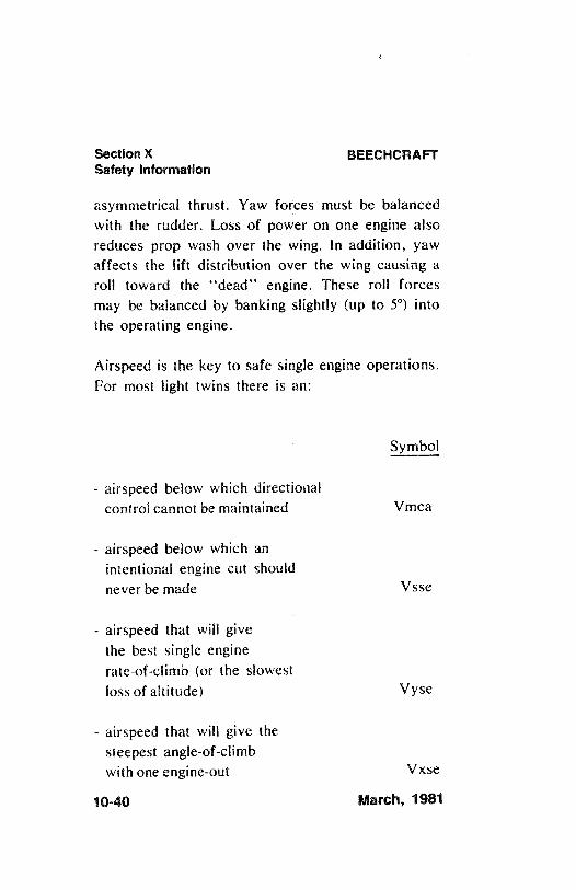
Section X BEECHCRAFTSafety information
asymmetrical thrust. Yaw forces must be balancedwith the rudder. Loss of power on one engine alsoreduces prop wash over the wing. In addition, yawaffects the lift distribution over the wing causing aroll toward the "dead" engine. These roll forcesmay be balanced by banking slightly (up to 5°) intothe operating engine.
Airspeed is the key to safe single engine operations.For most light twins there is an:
Symbol
- airspeed below which directionalcontrol cannot be maintained Vmca
- airspeed below which anintentional engine cut shouldnever be made Vsse
- airspeed that will givethe best single enginerate-of-climb (or the slowestloss of altitude) Vyse
- airspeed that will give thesteepest angle-of-climbwith one engine-out Vxse
10-40 March, 1981
BEECHCRAFT Section XSafety information
M/N/MUM CONTROL SPEED A/RBORNE (Vrnca)
Vmca is designated by the red radial on the airspeedindicator and indicates the minimum control speed,airborne at sea level. Vmca is determined by FAAregulations as the minimum airspeed at which it ispossible to recover difectional control of the airplanewithin 20 degrees heading change, and thereaftermaintain straight flight, with not more than 5 degreesof bank if one engine fails suddenly with:
- Take-off power on both engines,
- Rearmost allowable center of gravity,
- Flaps in takeoff position,
- Landing gear retracted,
- Propeller windmilling in takeoff pitchconfiguration (or feathered if automaticallyfeatherable).
However, sudden engine failures rarely occur with
all of the factors listed above, and therefore, theactual Vmca under any particular situation may be alittle slower than the red radial on the airspeed
March, 1981 10-41
Section X BEECHCRAFTSafety Information
indicator. Most airplanes will not maintain levelflight at speeds at or near Vmca. Consequently, it isnot advisable to fly at speeds approaching Vmca,except in training situations or during flight tests.Adhering to the practice of never flying at or belowthe published Vmc speed for your aircraft willvirtually eliminate loss of directional control as aproblem in the event of engine failure.
INTENT/ONAL ONE-ENG/NE INOPERAT/VE SPEED(Vsse)
Vsse is specified by the airplane manufacturer and isthe minimum speed at which to perform intentionalengine cuts. Use of Vsse is intended to reduce theaccident potential from loss of control after enginecuts at or near minimum control speed. Vmcademonstrations are necessary m trammg, but shouldonly be made at a safe altitude above the terrain andwith the power reduction on one engine made at orabove Vsse.
BEST S/NGLE ENG/NE RATE-OF-CL/MB SPEED(Vyse)
Vyse is designated by the blue radial on the airspeedindicator. Vyse delivers the greatest gain in altitude
10-42 March, 1981
BEECHCRAFT Section XSafety information
in the shortest possible time, and is based on thefollowing criteria:
- critical engine inoperative, and its propeller inthe minimum drag position.
- operating engine set at not more than maximumcontinuous power.
- landing gear retracted.- wing flaps in the most favorable (i.e., best
lift/drag ratio position).- cowl flaps as required for engine cooling.- aircraft flown at recommended bank angle.
Drag caused by a windmilling propeller, extendinglanding gear, or flaps in the landing position, will
severely degrade or destroy single engine climbperformance. Since engine climb performance varies
widely with type of airplane, weight, temperature,altitude, and airplane configuration, the climbgradient (altitude gain or loss per miler may bemarginal - or even negative - under some conditions.Study the Information Manual for your specificairplane and know what performance to expect with
one-engine out.
BEST S/NGLE ENGINE ANGLE-OF-CL/MB
A/RSPEED (Vxse)
Vxse is used only to clear obstructions during initial
March, 1981 10-43
l
Section X BEECHCRAFTSafety information
climb-out as it gives the greatest altitude gain perunit of horizontal distance. It provides less enginecooling and requires more rudder control than Vyse.
SINGLE ENGINE SERVIC/NGCE/LING
The single engine service ceiling is the maximumaltitude at which an airplane will climb, at a rate ofat least 50 feet per minute in smooth air, with oneengine feathered.
The single engine service ceiling chart should beused during flight planning to determine whether theairplane, as loaded, can maintain the MinimumEnroute Altitude (MEA) if IFR, or terrain clearanceif VFR, following an engine failure.
BAS/C SINGLE ENGINE PROCEDURES
Know and follow, to the letter, the single-engine
emergency procedures specified in your InformationManual for your specific make and model airplane.However, the basic fundamentals of all theprocedures are as follows:
- Maintain aircraft control and airspeed at all
times. This is cardinal rule No. 1.- Usually, apply maximum power to the operating
engine. However, if the engine failure occurs at
10-44 March, 1981
BEECHCRAFT Section XSafety information
a speed below Vmca, or during cruise or in a
steep turn, you may elect to use only enoughpower to maintain a safe speed and altitude. Ifthe failure occurs on final approach, use power
only as necessary to complete the landing.- Reduce drag to an absolute minimum.- Secure the failed engine and related sub-
systems.
The first three steps should be done promptly andfrom memory. The check list should then beconsulted to be sure that the inoperative engine issecured properly and that the appropriate switchesare placed in the correct position. The airplane mustbe banked about 5° into the live engine, with the"slip/skid" ball out of center toward the live engine,to achieve rated performance.
Another note of caution: Be sure to identify the deadengine, positively, before feathering it. Remember:First, identify the suspected engine (i.e., "Dead footmeans dead engine"), second, verify with cautiousthrottle movement, then feather.
ENGINE FAILURE ON TAKE-OFF
If an engine fails before attaining lift-off speed, orbelow Vmca, the only proper action is to discontinue
March, 1981 10-45
Section X BEECHCRAFTSafety Information
the take-off. If the engine fails after lift-off with thelanding gear still down, the take-off should still bediscontinued if touch-down and roll-out on theremaining runway is still possible.
If you do find yourself in a position of not beingable to climb, it is much better to pull the power onthe good engine and land straight ahead than try toforce a climb and lose control.
Your Information Manual contains charts that areused in calculating the runway length required tostop if the engine fails before reaching lift-off speedand also has charts showing single engineperformance after lift-off.
Study your charts carefully. No airplane is capableof climbing out on one engine under all weight,pressure altitude, and temperature conditions.Know, before you take the actual runway, whether
you can maintain control and climb-out if you losean engine while the gear is still down. It may benecessary to off-load some weight, or wait for morefavorable temperature or wind conditions.
WHEN TO FLY Vx, Vy, Vxse and Vyse
During normal two-engine operations, always fly Vy(Vx if necessary for obstacle clearance) on initial
10-46 March, 1981
BEECHCRAFT Section XSafety information
climb-out. Then, accelerate to your cruise climbairspeed, which may be Vy plus 10 to 15 knots afteryou have obtained a safe altitude. Use of cruiseclimb airspeed will give you better engine cooling,increased inflight visibility and better fuel economy.However, at the first indication of an engine failureduring climb-out, or while on approach, establishVyse or Vxse, whichever is appropriate. (Consultyour Information Manual for specifics).
STALLS,SLOVVFLIGHT AND TRA/NING
The stall warning system must be kept operational atall times and must not be deactivated by interruptionof circuits, circuit breakers, or fuses. Compliancewith this requirement is especially important in allhigh performance single and multi-engine airplanesduring engine-out practice, or stall demonstrations,because the stall speed is critical in all low speedoperations of high-performance airplanes.
Training should be accomplished under thesupervision of a qualified instructor-pilot; with
careful reference to the applicable sections of theFAA Flight Test Guide and FAA Pilot TransitionCourses for Complex Single Engine and Light TwinEngine Airplanes (AC61-9B). In particular, observecarefully the warnings in the flight test guides.
March, 1981 10-47
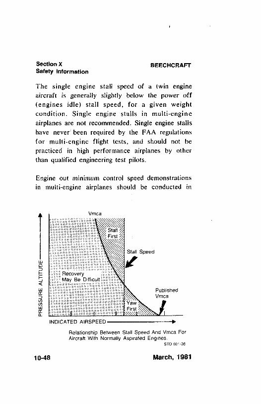
Section X BEECHCRAFTSafety Information
The single engine stall speed of a twin engineaircraft is generally slightly below the power off(engines idle) stall speed, for a given weightcondition. Single engine stalls in multi-engineairplanes are not recommended. Single engine stallshave never been required by the FAA regulationsfor multi-engine flight tests, and should not bepracticed in high performance airplanes by otherthan qualified engineering test pilots.
Engine out minimum control speed demonstrationsin multi-engine airplanes should be conducted in
Vmca
StallFirst
Stall Speed
RecoveryMay Be Difficult
PublishedVmca
o Yaww First
INDICATED AIRSPEED
Relationship Between Stall Speed And Vmca ForAircraft With Normally Aspirated Engines.
STD 601-38
10-48 March, 1981
BEECHCRAFT Section XSafety information
strict accordance with the warning of the FAAFlight Test Guide. Engine out minimum controlspeed generally decreases with altitude, while thesingle engine stall speed remains approximatelyconstant, for normally aspirated engines. No suchdemonstration should be attempted when the densityaltitude and temperature are such that the engine outminimum control speed is known, or discovered tobe, close to the stalling speed. Loss of directional orlateral control, just as a stall occurs, is potentially
hazardous.
Vsse, the airspeed below which an engine should notbe intentionally rendered inoperative for practicepurposes, was established because of the apparentpractice of some pilots, instructors, and examiners,of intentionally rendering an engine inoperative at atime when the airplane is being operated at a speedclose to, or below the power idle stall speed. Unlessthe pilot takes immediate and proper correctiveaction under such circumstances, it is possible toenter an inadvertent spin.
It is recognized that flight below Vsse with oneengine inoperative, or simulated inoperative, may berequired for conditions such as practicedemonstration of Vmca for multi-engine pilotcertification. Refer to the procedure set forth in theInformation Manual for your aircraft. This
March, 1981 10-49
Section X BEECHCRAFTSafety Information
procedure calls for simulating one engine inoperativeby reducing the power lever (throttle) on one engineto idle while operating at an airspeed above Vsse.Power on the other engine is set at maximum, thenairspeed is reduced at approximately one knot persecond until either Vmca or stall warning isobtained. During this transition, rudder should beused to maintain directional control, and aileronsshould be used to maintain a 5° bank toward theoperative engine. At the first sign of either Vmca orstall warning (which may be evidenced by inabilityto maintain longitudinal, lateral or directionalcontrol, aerodynamic stall buffet, or stall warning
horn sound), recovery must be initiated immediatelyby reducing power to idle on operative engine andlowering the nose to regain Vsse. Resume normalflight. This entire procedure should be used at a safealtitude of at least 5,000 feet above the ground in
clear air only.
If stall warning is detected prior to the first sign ofVmca, an engine-out minimum control speeddemonstration cannot be accomplished under theexisting density altitude and gross weight conditionsand should not be attempted.
SP/NS
A major cause of fatal accidents in general aviation
10-50 March, 1981
BEECHCRAFT Section XSafety information
aircraft is a stall and spin. Stall demonstrations andpractice are a means for a pilot to acquire the skillsto recognize when a stall is about to occur and torecover as soon as the first signs of a stall areevident. If a stall does not occur - A spin cannotoccur. It is important to remember however, that a
an occur in any flight attitude, at any airspeed,if controls are misused.
Unless your aircraft has been specificallycertificated in the aerobatic category and specificallytested for spin recovery characteristics, it isplacarded against intentional spins. The pilot of anairplane placarded against intentional spins shouldassume that the airplane may become uncontrollablein a spin, since its performance characteristicsbeyond certain limits specified in the FAAregulations may not have been tested and areunknown. This is why aircraft are placarded againstintentional spins, and this is why stall avoidance isyour protection against an inadvertent spin.
Pilots are taught that intentional spins are entered bydeliberately inducing a yawing movement with thecontrols as the aircraft is stalled. Inadvertent spinsresult from the same combination - stall plus yaw.That is why it is important to use coordinatedcontrols and to recover at the first indication of astall when practicing stalls.
March, 1981 10-51
Section X BEECHCRAFTSafety Information
In any twin engine airplane, fundamentalaerodynamics dictate that if the airplane is allowedto become fully stalled while one engine is providinglift-producing thrust the yawing movement whichcan induce a spin will be present. Consequently, it isimportant to immediately reduce power on theoperating engine, lower the nose to reduce the angleof attack, and increase the airspeed to recover fromthe stall. In any twin engine aircraft, if applicationof stall recovery controls is delayed a rapid rollingand yawing motion may develop, even against fullaileron and rudder, resulting in the airplanebecoming inverted during the onset of a spinningmotion. Once the airplane has been permitted toprogress beyond the stall and is allowed to reach therapid rolling and yawing condition, the pilot mustthen immediately initiate the generally accepted spinrecovery procedure for multi-engine airplanes, which
is as follows:
Immediately move the control column fullforward, apply full rudder opposite to thedirection of the spin and reduce power onboth engines to idle. These three actionsshould be done as near simultaneously aspossible; then continue to hold thiscontrol position until rotation stops and
then neutralize all controls and execute a
10-52 March, 1981
BEECHCRAFT Section XSafety Information
smooth pullout. Ailerons should beneutral during recovery. THE LONGERTHE PILOT DELAYS BEFORETAKING PROPER CORRECTIVEACTION, THE MORE DIFFICULTRECOVERY WILL BECOME.
Always remember that extra alertness and pilottechniques are required for slow flight maneuvers,including the practice or demonstration of stalls orVmca. In addition to the foregoing mandatoryprocedures, always:
1. Be certain that the center of gravity of theairplane is as far forward as possible. ForwardC.G. aids stall recovery, spin avoidance andspin recovery. An aft C.G. can create atendency for a spin to flatten out, which delaysrecovery.
2. Whenever a student pilot will be required topractice slow flight or single-engine maneuvers,be certain that the qualified instructor pilot hasa full set of operable controls in front of him.FAA regulations prohibit flight instructionwithout full dual controls.
3. Conduct any maneuvers which could possiblyresult in a spin at altitudes in excess of fivethousand (5,000) feet above ground level in clear
air only.
March, 1981 10-53
i
Section X BEECHCRAFTSafety information
4. Remember that an airplane, at or near traffic
pattern and approach altitudes, cannot recoverfrom a spin, or perhaps even a stall, beforeimpact with the ground. For twin engineaircraft, when descending to traffic altitude andduring pattern entry and all other flightoperations, maintain speed no lower than Vsse.On final approach maintain at least the airspeedshown in the flight manual. Should a go-around
be required, do not apply more power thannecessary until the airplane has accelerated toVsse. Recognize that under some conditions ofweight, density altitude, and aircraftconfiguration, a twin engine aircraft cannotclimb or accelerate on a single engine. Hence a
single engine go-around is impossible and theaircraft is committed to a landing. Plan your
approach accordingly.5. Remember that if an aiiplane flown under
instrument conditions is permitted to stall orenter a spin, the pilot, without reference to thehorizon, is certain to become disoriented. Hemay be unable to recognize a stall, spin entry,or the spin condition and he may be unable todetermine even the direction of the rotation.
6. Finally, never forget that stall avoidance is yourbest protection against an inadvertent spin.
MAINTAIN g AIRSPEED.
10-54 March, 1981
BEECHCRAFT Section XSafety Information
DESCENT
In piston-powered airplanes, whether single or twinengines, supercharged or normally aspirated, it isnecessary to avoid prolonged descents with lowpower, as this produces two problems: (1)Excessively cool cylinder head temperatures whichcause premature engine wear, and (2) excessivelyrich mixtures due to idle enrichment (and altitude)which causes soot and lead deposits on the sparkplugs (fouling). The second of these is the moreserious consideration; the engine may not respond tothe throttle when it is desired to discontinue thedescent.
Both problems are amenable to one solution:maintain adequate power to keep cylinder headtemperatures in the "green" range during descent,and lean to best power mixture (that is,progressively enrich the mixture from cruise onlyslightly as altitude decreases). This procedure will
lengthen the descent, of course, and requires some
advance planning.
If it is necessary to make a prolonged descent at ornear idle, as in practicing forced landings, at leastavoid the problem of fouled spark plugs byfrequently advancing the throttle until the engineruns smoothly, and maintain an appropriate mixture
March 1981 10-55
Section X BEECHCRAFTSafety Information
setting with altitude. (Refer to pre-landing check
list.)
VORTICES - WAKE TURBULENCE
Every airplane generates wakes of turbulence whilein flight. Part of this is from the propeller or jetengine, and part from the wing tip vortices. Thelarger and heavier the airplane, the more pronouncedand turbulent the wakes will be. Wing tip vorticesfrom large, heavy airplanes are very severe at closerange, degenerating with time, wind, and space.These are rolling in nature, from each wing tip. Intests, vortex velocities of 133 knots have beenrecorded.
Encountering the rolling effect of wing tip vorticeswithin two minutes after passage of large airplanes ismost hazardous to light airplanes. This roll effectcan exceed the maximum counter roll obtainable in alight airplane.
The turbulent areas may remain for as long as threeminutes or more, depending on wind conditions, andmay extend several miles beyond the airplane. Planto fly slightly above and to the windward side of theother airplanes. Because of the wide variety ofconditions that can be encountered, there is no setrule to follow to avoid wake turbulence in all
10-56 March, 1981
BEECHCRAFT Section XSafety information
situations. However, the Airman's InformationManual, and to a greater extent Advisory Circular90-23, Aircraft Wake Turbulence, provides athorough discussion of the factors you should beaware of when wake turbulence may beencountered.
TAKEOFF AND LAND/NGCOND/T/ONS
When taking off on runways covered with water orfreezing slush, the landing gear should remainextended for approximately ten seconds longer thannormal, allowing the wheels to spin and dissipate thefreezing moisture. The landing gear should then becycled up, then down, wait approximately fiveseconds and then retract again.
Caution must be exercised to insure that the entireoperation is performed below Maximum LandingGear Operating Airspeed.
Use caution when landing on runways that arecovered by water or slush which cause hydroplaning(aquaplaning), a phenomenon that renders brakingand steering ineffective because of the lack ofsufficient surface friction. Snow and ice coveredrunways are also hazardous. The pilot should also bealert to the possibility of the brakes freezing.
March, 1981 10-57
Section X BEECHCRAFTSafety Information
Use caution when taking off or landing during gustywind conditions. Also be aware of the special windconditions caused by buildings or other obstructionslocated near the runway in a crosswind pattern.
MEDICAL FACTS FOR PILOTS
GENERAL
When the pilot enters the airplane, he becomes anintegral part of the man-machine system. He is justas essential to a successful flight as the controlsurfaces. To ignore the pilot in pre-flight planningwould be as senseless as failing to inspect theintegrity of the control surfaces or any other vital
part of the machine. The pilot himself has theresponsibility for determining his reliability prior toentering the airplane for flight. When piloting anairplane, an individual should be free of conditionswhich are harmful to alertness, ability to makecorrect decisions, and rapid reaction time.
FAT/GUE
Fatigue generally slows reaction times and causeserrors due to inattention. In addition to the mostcommon cause of fatigue; insufficient rest and lossof sleep, the pressures of business, financial
10-58 March, 1981
Section XBEECHCRAR Safety information
worries, and family problems can be importantcontributing factors. If you are tired, don't fly.
HYPOX/A
Hypoxia, in simple terms, is a lack of sufficientoxygen to keep the brain and other body tissuesfunctioning properly. There is a wide individualvariation in susceptibility to hypoxia. In addition toprogressívely insufficient oxygen at higher altitudes,anything interfering with the blood's ability to carryoxygen can contribute to hypoxia (anemias, carbonmonoxide, and certain drugs). Also, alcohol andvarious drugs decrease the brain's tolerance tohypoxia.
Your body has no built-in alarm system to let youknow when you are not getting enough oxygen. It isimpossible to predict when or where hypoxia willoccur during a given flight, or how it will manifestitself. Some of the common symptoms of hypoxiaare increased breathing rate, a light-headed or dizzysensation, tingling or warm sensation, sweating,reduced visual field, sleepiness, blue coloring ofskin, fingernails, and lips, and behavior changes. Aparticularly dangerous feature of hypoxia is anincreased sense of well-being, called euphoria. Itobscures a person's ability and desire to be criticalof himself, slows reaction time, and impairs thinking
March, 1981 10-59
Section X BEECHCRAFTSafety Information
ability. Consequently, an hypoxic individualcommonly believes things are getting progressively
better while he nears total collapse.
The symptoms are slow but progressive, insidious inonset, and are most marked at altitudes startingabove ten thousand feet. Night vision, however, canbe impaired starting at an altitude of 5,000 feet.Persons who have recently overindulged in alcohol,who are moderate to heavy smokers, or who takecertain drugs, may be more susceptible to hypoxia.Susceptibility may also vary in the same individualfrom day to day or even morning to evening. Useoxygen on flights above 10,000 feet and at any timewhen symptoms appear.
Depending upon altitude, an hypoxic individual has alimited time to make decisions and perform usefulacts, even though he may remain conscious for alonger period. If pressurization equipment fails atcertain altitudes the pilot and passengers have only acertain amount of time to get an oxygen mask onbefore they exceed their time of usefulconsciousness. The time of useful consciousness isapproximately 3-5 minutes at 25,000 feet of altitudein the average individual and diminishes markedly asaltitude increases. At 30,000 feet altitude, for
10-60 March, 1981
BEECHCRAFT Section XSafety Information
example, the time of useful consciousness isapproximately I to 2 minutes. Therefore, in theevent of depressurization, oxygen masks should beobtained and used immediately.
Should symptoms occur that cannot definitely beidentified as either hypoxia or hyperventilation, trythree or four deep breaths of oxygen. The symptomsshould improve markedly if the condition washypoxia (recovery from hypoxia is rapid).
HYPERVENT/LATION
Hyperventilation, or overbreathing, is a disturbanceof respiration that may occur in individuals as aresult of emotional tension or anxiety. Underconditions of emotional stress, fright, or pain,breathing rate may increase, causing increased lungventilation, although the carbon dioxide output ofthe body cells does not increase. As a result, carbondioxide is "washed out" of the blood. The mostcommon symptoms of hyperventilation are:dizziness; hot and cold sensations; tingling of thehands, legs and feet; tetany; nausea; sleepiness; andfinally, unconsciousness. If the symptoms persist,discontinue use of oxygen and consciously slowyour breathing rate until symptoms clear, and thenresume normal breathing rate. Normal breathing canbe aided by talking aloud.
March, 1981 10-61
i
Section X BEECHCRAFTSafety Information
ALCOHOL
Common sense and scientific evidence dictate thatyou must not fly as a crew member while under theinfluence of alcohol. Alcohol, even in smallamounts, produces, among other things, a dulling ofcritical judgment; a decreased sense of responsibility;diminished skill reactions and coordination;decreased speed and strength of muscular reflexes(even after one ounce of alcohol); decreases inefficiency of eye movements during reading (afterone ounce of alcohol); increased frequency of errors(after one ounce of alcohol); constriction of visual
fields; decreased ability to see under dimilluminations; loss of efficiency of sense of touch;decrease of memory and reasoning ability; increasedsusceptibility to fatigue and decreased attentionspan; decreased relevance of response; increased self
confidence with decreased insight into immediatecapabilities.
Tests have shown that pilots commit major errors ofjudgment and procedure at blood alcohol levelssubstantially less than the minimum legal levels ofintoxication for most states. These tests furthershow a continuation of impairment from alcohol upto as many as 14 hours after consumption, with noappreciable diminution of impairment. The bodymetabolizes ingested alcohol at a rate of about one-
10-62 March, 1981
BEECHCRAFT Section XSafety information
third of an ounce per hour. Even after the bodycompletely destroys a moderate amount of alcohol, apilot can still be severely impaired for many hoursby hangover.
The effects of alcohol on the body are magnified ataltitudes, as 2 oz. of alcohol at 18,000 feet producethe same adverse effects as 6 oz. at sea level. Inother words, "the higher you get, the higher youget".
Because of the slow destruction of alcohol by thebody, a pilot may still be under influence eight hoursafter drinking a moderate amount of alcohol.Therefore, an excellent rule is to allow at least 12 to24 hours between "bottle and throttle", dependingon the amount of alcoholic beverage consumed.
DRUGS
Self-medication or taking medicine in any form whenyou are flying can be extremely hazardous. Evensimple home or over-the-counter remedies and drugssuch as aspirin, antihistamines, cold tablets, coughmixtures, laxatives, tranquilizers, and appetitesuppressors, may seriously impair the judgment andcoordination needed while flying. The safest rule isto take no medicine before or while flying, except
March, 1981 10-63
Section X BEECHCRAFTSafety information
after consultation with your Aviation MedicalExaminer.
SCUBA D/VING
Flying shortly after any prolonged scuba divingcould be dangerous. Under the increased pressure ofthe water, excess nitrogen is absorbed into yoursystem. If sufficient time has not elapsed prior totakeoff for your system to rid itself of this excessgas, you may experience the bends at altitudes evenunder 10,000 feet, where most light planes fly.
CARBON MONOX/DEAND N/GHT VIS/ON
The presence of carbon monoxide results in hypoxiawhich will affect night vision in the same mannerand extent as hypoxia from high altitudes. Evensmall levels of carbon monoxide have the sameeffect as an altitude increase of 8,000 to 10,000 feet.Smoking several cigarettes can result in a carbonmonoxide saturation sufficient to effect visualsensitivity equal to an increase of 8,000 feet altitude.
ADDITIONAL INFORMATION
In addition to the coverage of subjects in this
10-64 March, 1981
BEECHCRAFT Section XSafety Information
section, the National Transportation Safety Boardand the Federal Aviation Administration periodicallyissue, in greater detail, general aviation pamphletsconcerning aviation safety. FAA Regional Officesalso publish material under the FAA GeneralAviation Accident Prevention Program. These canbe obtained at FAA Offices, Weather Stations,Flight Service Stations or Airport Facilities, and arevery good sources of information and are highlyrecommended for study. Some of these are titled:
Airman's Information Manual12 Golden Rules for PilotsWeather or NotDisorientationPlane SenseWeather Info Guide for PilotsWake TurbulenceDon't Trust to Luck, Trust to SafetyRain, Fog, SnowThunderstorm - TRWIcingPilot's Weather Briefing GuideThunderstorms Don't Flirt . . . Skirt 'emIFR-VFR - Either Way Disorientation Can be FatalIFR Pilot Exam-O-GramsVFR Pilot Exam-O-GramsFlying Light Twins Safely
March, 1981 10-65
Section X BEECHCRAFTSafety Information
Tips on Engine Operation in Small General AviationAircraft
Estimating Inflight VisibilityIs the Aircraft Ready for FlightTips on Mountain FlyingTips on Desert FlyingAlways Leave Yourself An OutSafety Guide for Private Aircraft OwnersTips on How to Use the Flight PlannerTips on the Use of Ailerons and RudderSome Hard Facts About Soft LandingsPropeller Operation and CareTorque "What it Means to the Pilot"Weight and Balance. An Important Safety
Consideration for Pilots
SPECIAL CONDITIONS
MA/NTENANCE
Airplanes operated for Air Taxi or other than normaloperation, and airplanes operated in humid tropics,or cold and damp climates, etc., may need morefrequent inspections for wear, corrosion and/or lackof lubrication. In these areas, periodic inspectionsshould be performed until the operator can set hisown inspection periods based on experience.
10-66 March, 1981