Embed Size (px)
Citation preview
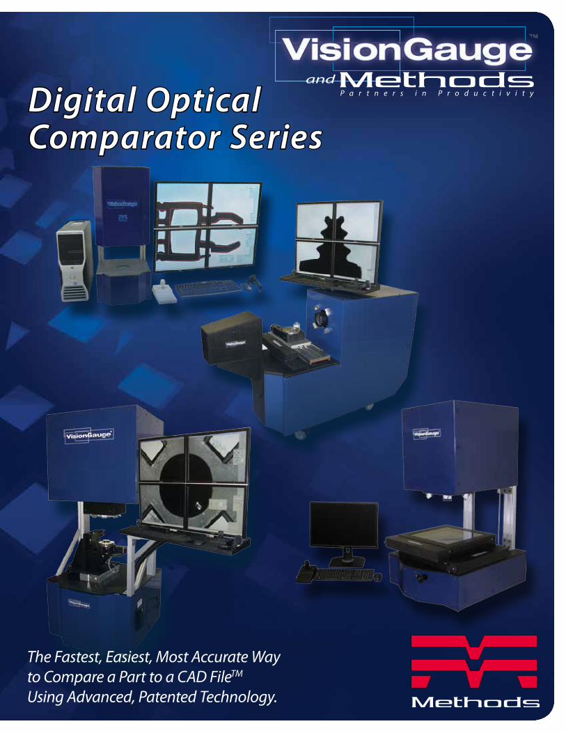
The Fastest, Easiest, Most Accurate Way to Compare a Part to a CAD FileTM
Using Advanced, Patented Technology.
Digital OpticalComparator Series
andP a r t n e r s i n P r o d u c t i v i t y

VisionGauge® 500 SeriesVisionGauge® Digital Optical Comparators allow you to quickly, easily and very accurately compare a part with its CAD drawing.
z
The VisionGauge® Digital optical Comparator can also be integrated into an automated work cell and controlled via Ethernet or RS-232 communications.
The VisionGauge® Digital Optical Comparator (Patented & Other Patents Pending) is a fully-digital drop-in replacement for traditional optical comparators. It works directly with your part’s CAD data and doesn’t require any overlays.
The system is extremely easy to use, and thanks to its advanced, patented CAD
Auto-Align™ and CAD Auto-Pass/Fail™ tools, operators can compare parts to their CAD data completely automatically, directly on the shop floor.
The VisionGauge® Digital Optical Comparator eliminates operator error and can automatically collect complete electronic documentation including measurements, statistics, Pass/Fail results, a high-resolution image of the part with its CAD overlay, etc.
1

The main benefits of the VisionGauge® Digital Optical Comparator are:• Increased accuracy
• Higher throughput
• Eliminate operator-dependent variations
• Advanced patented “CAD Auto-Align™” tool to automatically line up the CAD file to the part along one or multiple datums or carry out an “overall best fit”
• Advanced patented “CAD Auto Pass/Fail™” tool to automatically compute the deviation from nominal and compare it to bi-directional tolerances, in real-time, and produce a high-accuracy fully automated Pass/Fail result.
• Works directly with your existing CAD data/Doesn’t require any overlays
• Automatically collect complete electronic documentation/device history
• Reduced floor space requirements/Smaller footprint
• Carry out inspections & measurements directly on the shop floor
• Allows you to compare parts to their CAD data beyond the optical field-of-view (across the entire stage travel)
• Much greater depth of field (i.e. “everything is in focus at once“)
• Can be moved very easily and without requiring re-calibration
2

Rotary AxesSupplementary
Mounted with rotary axis aligned either vertically or horizontally. Note that multiple rotary stages can also be used (to provide “Pan & Tilt” capability, for
example). Custom fixturing is also available for turnkey projects.
3
Rotary Axes
Model Number
Field-of-View
Horizontalinches
Verticalinches
Diagonalinches
Horizontalmm
Verticalmm
Diagonalmm
VGDOC-30H-5/10/20XVGDOC-30V-5/10/20X
4.73.1
1.55
3.52.31.09
5.93.91.89
119.478.7
39.37
88.958.427.66
148.898.048.12
VGDOC-30H-10/20/50XVGDOC-30V-10/20/50X
2.421.210.61
1.820.920.46
3.031.520.64
61.530.7313.13
46.223.379.73
76.938.6116.34
VGDOC-30H-20/50/100XVGDOC-30V-20/50/100X
1.550.521.55
1.090.381.09
1.890.641.89
39.3713.1339.37
27.669.7327.66
48.1216.3448.12
Model Number
Field-of-View Working Distanceinches(mm)
Depthof
Fieldinches(mm)
Horizontalinches(mm)
Verticalinches(mm)
Diagonalinches(mm)
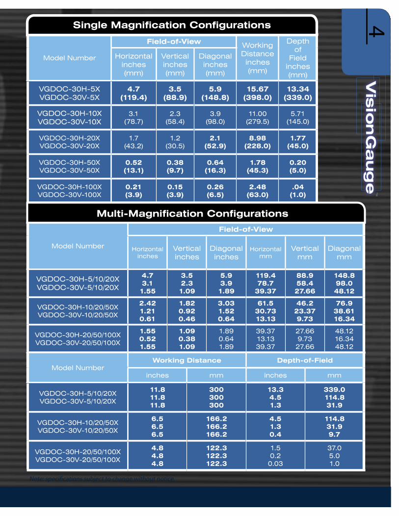
VGDOC-30H-5X VGDOC-30V-5X
4.7 (119.4)
3.5(88.9)
5.9(148.8)
15.67(398.0)
13.34(339.0)
VGDOC-30H-10X VGDOC-30V-10X
3.1(78.7)
2.3(58.4)
3.9(98.0)
11.00(279.5)
5.71(145.0)
VGDOC-30H-20XVGDOC-30V-20X
1.7(43.2)
1.2(30.5)
2.1(52.9)
8.98(228.0)
1.77(45.0)
VGDOC-30H-50X VGDOC-30V-50X
0.52(13.1)
0.38(9.7)
0.64(16.3)
1.78(45.3)
0.20(5.0)
VGDOC-30H-100XVGDOC-30V-100X
0.21(3.9)
0.15(3.9)
0.26(6.5)
2.48(63.0)
.04(1.0)
Single Magnification Configurations
Note: specifications subject to change without notice.
Model NumberWorking Distance Depth-of-Field
inches mm inches mm
VGDOC-30H-5/10/20XVGDOC-30V-5/10/20X
11.811.811.8
300300300
13.34.51.3
339.0114.831.9
VGDOC-30H-10/20/50XVGDOC-30V-10/20/50X
6.56.56.5
166.2166.2166.2
4.51.30.4
114.831.99.7
VGDOC-30H-20/50/100XVGDOC-30V-20/50/100X
4.84.84.8
122.3122.3122.3
1.50.20.03
37.05.01.0
Multi-Magnification Configurations
4

Specialized illumination modules are also available to make features of interest stand out and eliminate glare and reflections.
Specialized Illumination Modules
Glare No Glare
50XMagnification
z
5

Specialized Illumination Modules
Optional Laser Module
For fast and accurate depth and height measurements (either manual or fully-automated), the LASER’s software interface is seamlessly integrated with all of the systems other tools.
Fast, accurate and easy-to-use reverse engineering tools - when you have a part and want to create its CAD file.
The ideal solution for checking profile tolerances!
6

Available Options
Part Number Description
VGDOC-30-RIHigh-intensity LED reflected illumination module
(programmable and computer-controlled) fully integrated with VisionGauge® Digital Optical Comparator
VGDOC-30-CAL
Adapted NIST-traceable stage micrometer with certificate of calibration (this will allow you to carry out the yearly re-
calibration yourselves). Note: this stage micrometer is especially designed for the VisionGauge® Digital Optical Comparator
VGDOC-30-01XY Upgrade of the X- and Y-axis encoders from 0.5 um resolution to 0.1 um resolution. Applicable for either the horizontal or vertical configuration of the VisionGauge® Digital Optical Comparator
VGDOC-24XHExtended (i.e. 24”) X-axis travel stage upgrade (from the standard
12” travel) for Horizontal configuration VisionGauge® Digital Optical Comparator
VGDOC-12YHExtended (i.e. 12”) Y-axis travel column upgrade (from
the standard 6” travel) for Horizontal configuration VisionGauge® Digital Optical Comparator
VGDOC-24X24YVExtended (i.e. 24” x 24”) X-axis and Y-axis travel stage
upgrade (from the standard 12” x 12” travel) for the Vertical configuration VisionGauge® Digital Optical Comparator
VGDOC-12ZExtended (i.e. 12”) Z-axis travel. Applicable for either the horizontal or vertical configuration of the VisionGauge® Digital Optical Comparator
VGDOC-30-XMON“5th monitor option” to automatically load and display inspection
instructions & criteria or other related documents when the work order barcode is scanned to automatically load the appropriate CAD file
VGDOC-30-COAXRI
On-axis reflected LED illumination module (programmable and computer-controlled) fully integrated with VisionGauge® Digital Optical Comparator. This reflected (i.e. “front”) illumination module produces
a very different type of front illumination that is very “flat” (i.e. “shadow free” and low glare) that is more appropriate for certain types of parts.
This illumination module is mounted on a “swing arm” to allow the operator to easily put it in position & retract it when it is not needed.
VisionGauge® 500 Series Options7

Available Options
Part Number Description
VGDOC-30-RS
4th motorized axis with encoded rotary stage (i.e. to rotate the part), including:• All required motion control hardware for 4th motorized axis (for part
rotation). This motion control hardware is completely and seamlessly integrated with the system’s existing motion control hardware
• Motorized encoded high-accuracy rotary stage• Fixture to mount the stage to the system’s dovetail grooves • All required cables & power supplies
VGDOC-30-LASER
LASER module for Z-axis measurements, including:• High-accuracy structured LASER module • LASER controller hardware (to completely control the
LASER’s operation from within the software)• Adapted fixture to mount the LASER module onto the Z axis stage• Software upgrade• All required cables & power supplies
VGDOC-SASWLOptional standalone “desktop” software license (to allow you to remotely view your CAD files, setup tolerances, create automated inspection and measurement programs, etc...)
VGDOC-ASUP- Renewal
VisionGauge® Annual Support and Update Program Membership Renewal (which provides users with unlimited technical support and free software updates for a full 1-year period). Note that unlimited technical support and free software updates are included for the 1st year with every VisionGauge® Digital Optical Comparator (Patent Pending) system.
VGDOC-EW2
2nd year hardware warranty for the VisionGauge® Digital Optical Comparator (i.e. the VisionGauge® Digital Optical Comparator comes with a complete 1 year hardware warranty and this optional item extends it to the 2nd year).
VGDOC-RAF Replacement air filter
Other accessories, system configurations, fixturing, etc. available upon request. Please inquire.
8

500 Series Specifications
Horizontal Configurations Vertical Configurations
Standard Optical Magnifications
(equivalent to traditional comparators)
5X, 10X, 20X, 50X and 100X 1
Image view area 33.5” wide x 25.75” high (= 42” diagonal)
Software InterfaceIntuitive, Windows-based graphical user interface
(i.e. “point & click”)
Motorized X-, Y- & Z-axes Yes
X-, Y- & Z-stage movement High-accuracy crossed-roller movement
X-axis travel 12” 2
Y-axis travel 6” 2 12” 2
X- & Y-axis encoder resolution
0.25 micron 3
Z stage travel 4” 2
Auto-Focus Yes
Part fixturing configuration
Dual standard dovetail groovesThreaded mounting
hole pattern
Encoded Z-axis Optional 4
LASER module (for Z-axis measurement)
Optional 4
High-accuracy rotary axes Optional 4
Fully programmable 3D motion
Yes
Camera High-resolution, digital (9 MegaPixel)
Illumination
• LED-based (for very stable illumination conditions, with a very long life)
• Programmable & computer-controlled (for repeatable illumination conditions)
• Both reflected (i.e. front) & transmitted (i.e. back) illumination modules are available
LensVery low distortion telecentric, with long working
distance & extended depth-of-field
VisionGauge® 500 Series Specifications
9

Horizontal Configurations Vertical Configurations
Real-time mathematical image processing,
enhancement and correctionYes
Patented CAD Auto-Align™ tool Yes, with user-specified bi-directional tolerances
Patented CAD Auto-Pass/Fail tool
Yes, with user-specified bi-directional tolerances
Extended set of high-accuracy measurement tools
Yes, with sub-pixel-accurate edge detection
Image annotation tools Yes
Automatic electronic documentation
Yes
Built-in SPC capabilities, with automatic numerical charts & PASS/FAIL graphs, etc...
Yes
Automatic data export to ExcelTM and other applications
Yes
Compare a part to its CAD data across the entire stage travel
Yes
Quick CAD data and settings change over & recall
Yes (“1-button recall”)
Supervisor/operator password protection
Yes
Operating System WindowsTM 7 5
Built-in “F1 Help” Yes
Fan & filter unit on main cabinet Yes (to create a positive pressure and keep dust out)
Power requirements (North America)
110V, 15 Amp (single cord)
Operating temperature 10 °C - 30 °C
Support (by phone, fax & email) Included for a full year
Warranty 1 year (complete)
VisionGauge® 500 Series Specifications
1 Available in both single magnification and multi-mag configurations. Other optical magnifications available on request.2 Other stage travels available on request.3 Other encoder resolutions available on request.4 Because of the system’s extended depth of field, the Z-axis stage is used simply as a focusing stage. However, a Z-axis encoder is included in the optional LASER module for Z-axis measurement5 Other operating systems available on request.
Note: specifications subject to change without notice.
10

VisionGauge® 700 SeriesThe 700 Series VisionGauge® Digital Optical Comparator is thePerfect Solution for Checking EDM- and LASER-Drilled Holes and Slots
• 5 axes of motion (X, Y, Z, Rotary Tilt) to properly view parts from all sides & angles
• Fully-automated operation
• No operator-to-operator variation
• Easy to program (can use your CAD data directly)
• Fast, accurate & easy-to-use
• Extensive set of measurement tools
• Straightforward operator interface: barcode-reader and joystick
• Intuitive software
• Patented & patent-pending technology
• Powerful & innovative software tools for robust feature detection
• Sharp, clear & ultra-high resolution image!
• Ultra-bright all-LED computer controlled multi-angle and multiquadrant illumination is standard!
• High-resolution precision optics to make out very fine details with great clarity
• Extended optical depth of field and extended working distance for maximum flexibility
• Automatically create reports and collect measurements, statistics, images and other data for complete documentation
• Automatic image & data collection with built-in SPC and data-exchange capabilities
• Fast and intuitive “operator review” mode to quickly revisit out-of-tolerance areas
• Robust shop-floor design
11

VisionGauge® 700 SeriesThe 700 Series VisionGauge® Digital Optical Comparator is the Perfect Solution for Checking EDM-Drilled HolesThere are many reasons why the VisionGauge® Digital Optical Comparator is widely used by manufacturers across a broad range of industries (including aerospace and power generation) to check EDM-drilled holes:
• Automatically verify hole presence & accurately measure hole location
• Supports both round and shaped holes
• 5 axes of motion (X, Y, Z, Rotary, Tilt) to properly view parts from all sides & angles
• Quickly, easily and accurately inspect 100% of the holes on your parts
• Robust shop floor design
• Can output the hole offsets which can be used to modify EDM drilling programs
• Mounting system allows your parts to go directly from the EDM drilling machine to the inspection system without re-fixturing (quick & easy and also minimizes stack-up error, etc...)
• The system can be supplied with the same working envelope as your EDM drill. If you can drill it, we can check it!
• Holes can be checked either one at a time, looking straight down each hole's nominal axis (ideal for coated parts, to minimize errors due to coating thickness variations) or multiple holes can be checked at once, viewing them at an angle (which is even faster and well suited for uncoated parts or parts with a uniform coating thickness)
• The system has an extended depth of field, so that everything is perfectly in focus regardless of the part's geometry (even in areas of very high curvature) as well as a very long working distance (so that there is lots of clearance between the part and the entire optical system to comfortably accommodate large and unusually-shaped parts)
• Extremely powerful "adaptive" feature-detection software tools are able to accurately find and locate EDM drilled holes on different surfaces, with different reflectivity, at different viewing angles, etc...
• Specialized software tools are especially well suited to deal with burrs and splatter
• Automatically create reports and collect measurements, statistics, images and other data for complete documentation
• Fast and intuitive "operator review" mode allows the operator to quickly revisit out-of-tolerance areas, etc...
The VisionGauge® Digital Optical Comparator is a very cost-effective, perfectly adapted solution for checking EDM-drilled holes. It is rapidly becoming the new standard in the industry!
Automatically Verify Hole Presence and Location
12

Number of motorized axes 5 (X, Y, Z, Tilt & Rotary)
Standard travels (note: extended travels available upon request)
VG700DOC-30V-20X VG700DOC-30V-XT1-20X
X-axis travel = 12” (300 mm)Y-axis travel = 12” (300 mm)Z-axis travel = 12” (300 mm)
X-axis travel = 24” (600 mm)Y-axis travel = 24” (600 mm)Z-axis travel = 24” (600 mm)
A (tilt) axis range from - 100° to +100°B (rotary) axis range from 0° to +360°
All axes have closed-loop encoder feedback
X-axis encoder resolution = 0.25 μmY-axis encoder resolution = 0.25 μmZ-axis encoder resolution = 0.25 μmA-axis encoder resolution = 0.005°B-axis encoder resolution = 0.005°
Stage movement X-, Y- and Z- axes: high-accuracy preloaded crossed-roller movement precision worm gear with high-accuracy preloaded crossed-roller movement
End-of-travel limits Optical (for high repeatability)
Mounting system System 3R Macro Chuck (p/n 3R-600.24-S)(Other mounting systems available upon request)
High-resolution optical system 20X equivalent optical magnification (approx.)Working distance = 9.0” (228 mm)Depth-of-field = 1.8” (45 mm)Field of view = 1.7” (43mm) x 1.2” (30 mm) = 2.1” (53 mm) ØOptical system accuracy: better than +/- 0.00015” (4 μm)
General-purpose dual-source reflected (i.e.
front) LED illumination
Ultra-bright, all-LED based (for stable and repeatable illumination conditions & results as well as long life)
Fully computer-controlled & programmableProduces very high brightness to easily handle even difficult-to-image areas
The system’s dual-source illumination module provides lighting at different angles of incidence (i.e. both near-vertical and low-oblique) for wide applicability across a very broad range of part geometries.
VisionGauge® Software Powerful and easy-to-useIntuitive, windows-based graphical user interface (i.e. “point & click”)Full 5-axis transformsAdvanced software corrections with full 3D mapping across the system’s entire work envelope
Includes a wide range of powerful inspection and measurement tools
Robust & field-proven, with a broad installed base (over 3500 license in use worldwide)
5-axis corrections Chuck offset, fixture height and fixture center-of-rotation (X,Y) offset
Software feature-detection tools Extremely powerful “adaptive” software feature-detection tools are able to accurately find and locate features of interest (such as EDM-drilled holes) on different surfaces, with different reflectivity, at different viewing angles, etc.
*Specifications subject to change without notice
700 Series Specifications
VisionGauge® 700 Series Specifications13
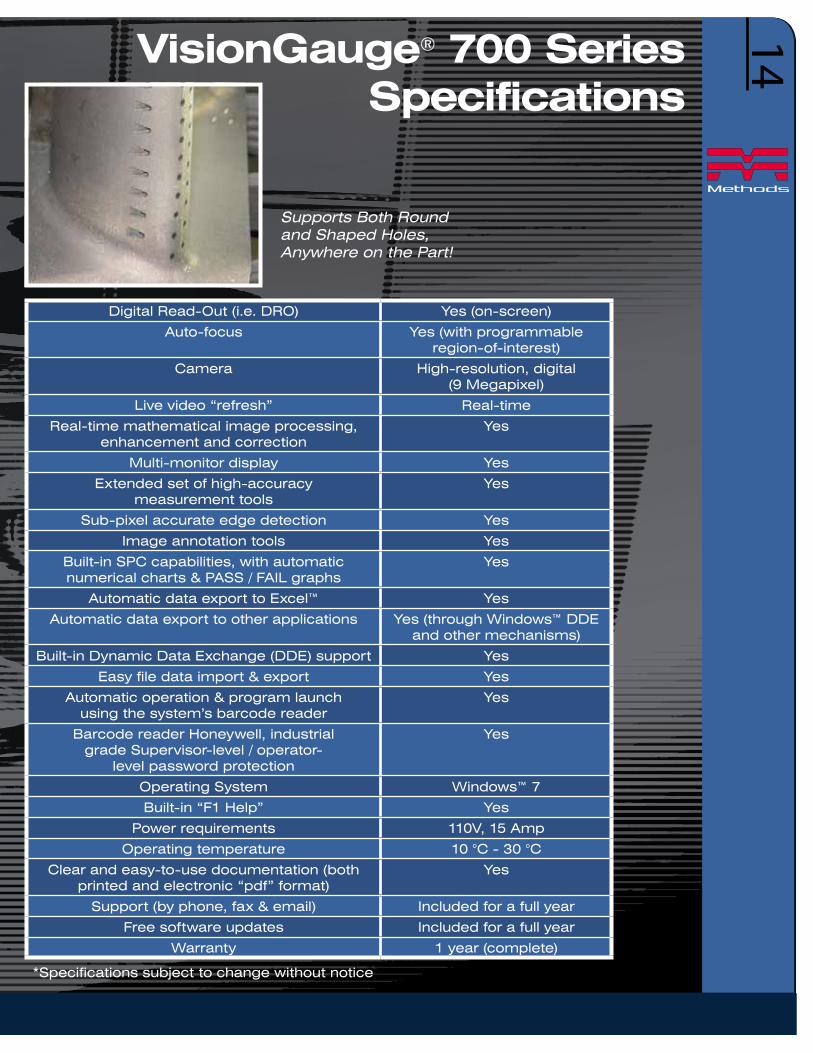
Digital Read-Out (i.e. DRO) Yes (on-screen)
Auto-focus Yes (with programmable region-of-interest)
Camera High-resolution, digital (9 Megapixel)
Live video “refresh” Real-time
Real-time mathematical image processing, enhancement and correction
Yes
Multi-monitor display Yes
Extended set of high-accuracy measurement tools
Yes
Sub-pixel accurate edge detection Yes
Image annotation tools Yes
Built-in SPC capabilities, with automatic numerical charts & PASS / FAIL graphs
Yes
Automatic data export to Excel™ Yes
Automatic data export to other applications Yes (through Windows™ DDE and other mechanisms)
Built-in Dynamic Data Exchange (DDE) support Yes
Easy file data import & export Yes
Automatic operation & program launch using the system’s barcode reader
Yes
Barcode reader Honeywell, industrial grade Supervisor-level / operator-
level password protection
Yes
Operating System Windows™ 7
Built-in “F1 Help” Yes
Power requirements 110V, 15 Amp
Operating temperature 10 °C - 30 °C
Clear and easy-to-use documentation (both printed and electronic “pdf” format)
Yes
Support (by phone, fax & email) Included for a full year
Free software updates Included for a full year
Warranty 1 year (complete)
*Specifications subject to change without notice
VisionGauge® 700 Series Specifications
Supports Both Round and Shaped Holes, Anywhere on the Part!
14

VisionGauge® 400 SeriesThe 400 Series VisionGauge® Digital Optical Comparator is a state-of-the-art inspection and measurement system.
• Compact desktop system with large measurement envelope (up to 12” x 12”)
• 3 axis inspection and measurement system with manual stage movements
• X- and Y-axes have 0.25 micron resolution encoders
• Optional LASER module for Z-axis measurements
• Single high-resolution monitor display. A 2nd monitor is available as an option
• Sharp & clear high resolution image
• Ultra-bright all-LED computer-controlled illumination
• High-resolution precision optics
• Single magnification optics with extended depth-of-field and long working distance for maximum flexibility
• Optical accuracy better than +/-0.00015” (i.e. 4 μm)
• Patented CAD Auto-Align™ and CAD Auto-PASS/FAIL™ software tools for fast, accurate and operator-independent Part-to-CAD Comparison
• Compare parts to their CAD file beyond the optical field-of-view, across the entire stage travel!
• Fast, accurate & easy-to-use
• Extensive set of measurement tools
• Intuitive software with a straightforward operator interface
• Automatically create reports and collect measurements, statistics, images and other data for complete documentation
• Automatic image & data collection with built-in SPC and data- exchange capabilities
• Robust design with no consumable parts
• Available in both Horizontal and Vertical Configurations!
It’s a compact desktop system, but at the same time it provides a large working envelope. The 400 Series is a very cost-effective, full-featured system that has all of the advanced, patented VisionGauge® software capabilities. This system is especially well suited for lower volume applications.
15

VisionGauge® 400 Series Patented VisionGauge® CAD Auto-AlignTM and CAD Auto-Pass/FailTM tools provide fast, accurate, and operator-independent results
The perfect solution for checking profile tolerances!
The system has a broad set of high-accuracy measurement tools.
Front and back illumination are available. Works on different surfaces and
materials, including metals and plastics.
16

Horizontal Configurations
Vertical Configurations
Machine Configuration Compact Desktop Unit
Number of Axes 3 (X, Y, Z)
Axes MovementAll 3 axes (X, Y, Z) have high-accuracy
preloaded crossed-roller bearings. The axes are all manually operated.
Closed Loop Encoder FeedbackX- and Y-axes have 0.25μm resolution closed-loop encoder
feedback. (0.25μm resolution Z-axis encoder available as option.)LASER Module
(For Z-Axis Measurement)Available as option
Standard Travels: X-Axis Y-Axis Z-Axis
12” (300mm) 6” (150mm) 4” (100mm)
12” (300mm) 12” (300mm) 4” (100mm)
Part Fixturing Configuration Dual Standard Dovetail Grooves Threaded Mounting Hole Pattern
Optical Magnification 20x (Equivalent)
Working Distance 9.0” (228mm)
Depth-of-Field 1.8” (45mm)
Field of View 1.7” (43mm) x 1.2” (30mm) = 2.1” (53mm) diag.
Optical System Accuracy < = ±0.00015” (4μm)
IlluminationAll illumination is fully computer-controlled and programmable,
and uses our ultra-bright, all-LED modules (for stable and repeatable illumination conditions and results, as well as long life)
Collimated Back (Transmitted) Illumination
Included
Standard Front (Reflected) Illumination
Available as an option
Specializes On-Axis Front (Reflected) Illumination
Available as an option
VisionGauge® Software
Powerful and easy to use.Intuitive, Windows-based graphical user
interface (i.e. “point and click”).Advanced Software corrections with full mapping
across the entire work envelope.Includes a wide range of powerful inspection
and measurement tools.Robust and field-proven, with a broad installed
base (over 3500 licenses in use worldwide).
Digital Read-Out (i.e. DRO) Yes (on screen)
Camera High-resolution, digital (9 Megapixel)
Live Video “Refresh” Real-time
Patented CAD Auto-AlignTM Tool Yes
Patented CAD Auto-Pass/FailTM Tool
Yes
VisionGauge® 400 Series Specifications
400 Series Specifications
17

VisionGauge® 400 Series Specifications
3-Axis 3- Speed joystick to quickly move and align the overlay (X, Y movement, as well as rotation)
Included (industrial grade, with protective boot)
Ability to compare the CAD File beyond the optical field-of-view,
across the entire stave travelYes
Real-time mathematical image processing, enhancement and correction
Yes
Image Display High resolution single monitor
2nd Monitor Available as option
Extended set of High Accuracy Measurement Tools
Yes
Sub-Pixel Accurate Edge Detection Yes
Image Annotation Tools Yes
Built-In SPC Capabilities, with automatic numerical charts and PASS/FAIL Graphs
Yes
Automatic Data export to ExcelTM Yes
Automatic Data export to other applications Yes (through WindowsTM DDE and other mechanisms)
Built-in Dynamic Data Exchange (DDE) support
Yes
Easy File Data Import & Export Yes
Barcode Reader Available as an option (Honeywell Industrial Grade)
Automatic Operation & Program Launch using the system’s barcode reader
Yes
Supervisor-level / Operator-level password protection
Yes
Operating System WindowsTM 7
Built-in “F1 Help” Yes
Power Requirements 110V, 15Amp (also available in 220V configuration)
Operating Temperature 10 °C - 30 °C
Clear and easy-to-use documentation (both printed and electronic pdf format)
Yes
Support (by phone, fax and email) Included for a full year
Free software updates Included for a full year
Warranty 1 year (complete)
Applicable across a wide range of industries!
18

VisionGauge® 300 Series
The 300 Series VisionGauge® Digital Optical Comparators are extremely cost effective Field-of-View Systems that are ideal for smaller parts.
They have an extended depth-of-field for tall parts and a long working distance that provides ample clearance and room to work between the part and the lens. They produce a stunning super-high-resolution image to carry out fine, de-tailed inspections.
Three different types of LED illumination are standard: collimated back, front off-axis (i.e. “dark field”) and front on-axis (i.e. “bright field”). This allows the system to produce crisp, sharp edges and perform beautifully even when working with
hard-to-image materials (for example: shiny, reflective or even translucent surfaces) and difficult geometries (such as deep holes).
VisionGauge® Digital Optical Comparators are complete, ready-to-run Windows-based solutions. They are delivered network-ready and include on-site installation, NIST-traceable calibration and training.
The 300 Series Field-of-View Systems are desktop instruments that have all of the functionality of the 500 Series VisionGauge® Digital Optical Comparators, with the sole exception that they are limited to smaller parts.
The VisionGauge® 300 Series Digital Optical Comparator is is extremely fast, easy-to-use, and ideal for smaller parts.
19

VisionGauge® 300 Series
• Intuitive software interface
• Innovative patent pending technology
• Joystick & bar code reader driven
• Automatic image & data collection
• Built-in SPC capability
• All-LED computer-controlled multi- illumination modules (back, front square- on and front oblique) are standard!
• High-resolution precision optics
• No moving parts
• No consumable parts
• Convenient desktop configuration
• Automatically collect measurements, statistics, images and other data for complete device history information
The VisionGauge® 300 Series Digital Optical Comparator is is extremely fast, easy-to-use, and ideal for smaller parts.
• Automatically compare parts to their CAD data with our patented CAD Auto-Align™ and patented CAD Auto Pass/Fail™ tools, in seconds
• Instantly computes and displays deviations-from-nominal and out-of-tolerance areas
• No operator-to-operator variation
• Needs no overlays, templates or MylarsTM
Full automated measurement capability.Accurate to +/- 0.0001” (2.5 μ)
Quickly and easily check flexible and other hard-to-inspect parts against their CAD data
Easy-to-use reverse engineering tools to create a CAD file from a part
Perfect for both the shop floor and the quality control lab!
The proprietary system can check multiple screws completely auto-matically, regardless of their orientation!
The best, highest resolution, sharpest image available!
20

VisionGauge® Comparators are Applicable Across a Wide Variety of Industries
300 Series Specifications
VG300DOC-30V-40X VG300DOC-30V-20X VG300DOC-30V-10X
Maximum part size (i.e. field-of-view dimensions)
0.85” (horizontal) x 0.60” (vertical)
(i.e. 1.0” diagonal)
1.7” (horizontal) x 1.2” (vertical)
(i.e. 2.0” diagonal)
3.1” (horizontal) x 2.3” (vertical)
(i.e. 3.9” diagonal)Maximum part height 0.2” 0.8” 3.0”
Vertical clearance (between the working surface and the lens)
4.1” 6.5” 8.9”
Equivalent optical magnification (approx.) 40X 20X 10X
“Desktop” configuration Yes
Image viewing area 33.5” wide x 25.75” high ( =42” diagonal)
Software interface Intuitive, Windows-based graphical user interface (i.e. “point & click”)Part fixturing configuration
(if desired)Tapped hole pattern on main working
surface surface (#10-24)Camera High-resolution, digital (9 MegaPixel)
Illumination
• LED-based (for very stable illumination conditions, with a very long life)
• Programmable and computer-controlled (for repeatable illumination conditions)
• Includes 3 different illumination modules: collimated transmitted (i.e. back), on-axis reflected (i.e. front) and oblique reflected (i.e. front) illumination modules are standard
Lens Very low distortion telecentric, long working distance & extended depth-of-field
Real-time mathematical image processing,
enhancement & correctionYes
Patented CAD Auto-Align™ tool
Yes: automatically align the CAD data to the part along an arbitrary number of user-specified datums
Patented CAD Auto Pass/Fail™ tool Yes, with user-specified bi-directional tolerances
Extended set of high-accuracy
measurement toolsYes, with sub-pixel-accurate edge detection
Image annotation tools YesAutomatic electronic
documentation Yes
Built-in SPC capabilities, with automatic numerical charts & PASS / FAIL graphs, etc...
Yes
Automatic data export to Excel TM
and other applicationsYes
Quick CAD data and settings changeover & recall Yes (“1-button recall”)
Supervisor & Operator password protection Yes
Supervisor & Operator password protection WindowsTM 7
Built-in “F1 Help” YesPower requirements
(North America) 110V, 15 Amp (single cord)
Operating temperature 10 °C - 30 °C Support (by phone,
fax & email) Included for a full year
Free software updates Included for a full year
Warranty 1 year (complete)
Note: specifications subject to change without notice.
21

VisionGauge® Comparators are Applicable Across a Wide Variety of Industries
Medical • Automotive • Aerospace & Aeronautics • Cutting ToolManufacturing • Extrusions • Military • Telecommunications Power & Energy • Machining • Tool & Die • And Many More!
andP a r t n e r s i n P r o d u c t i v i t y
22

©Methods Machine Tools, Inc. • Methods-VisionGauge Digital Optical Comparators 022015
T E C H N I C A L C E N T E R S F R O M C O A S T T O C O A S T
WWW . M E T H O D SM AC H I N E . C OM
M A C H I N E T O O L S T U R N K E Y S O L U T I O N S A U T O M A T I O N C E L L S P A R T S A N D S E R V I C E T O O L I N G
PHOENIX
602.437.2220
LOS ANGELES
714.521.2507
CHICAGO
847.783.6800
DETROIT
248.624.8601
CHARLOT TE
704.587.0507
BOSTON
978.443.5388
SAN FRANCISCO
510.636.1430
� � � �


![PrinCom [Encoded Handout VI].pdf](https://img.pdfslide.us/doc/110x75/55cf8ac355034654898d9215/princom-encoded-handout-vipdf.jpg)