Embed Size (px)
Citation preview
A N T H O N Y L I F T G A T E S , I N C .
I N S TA L L AT I O NAND
O PE R AT I O NMANTENANCE & TROUBLESHOOTING
I N S TA L L AT I O NAND
O PE R AT I O NMANTENANCE & TROUBLESHOOTING
Anthony Liftgates, Inc.1037 W. Howard Street • P.O. Box 615 • Pontiac, IL 61764-0615Ph: 815.842.3383 • Fax: 815.844.3612 • Toll Free: 800.482.0003www.anthonyliftgates.com
For AST and ATU Model Tuckunder LiftgatesFor AST and ATU Model Tuckunder Liftgates
MODELSAST-1500-SFAST-2000-SFAST-2500-SFAST-3000-SFASTL-1800-SFASTL-2500-SF
ATU-1800-SFATU-2500-SFATU-3000-SFATU-3500-SFATU-1800LB-SFATU-2500LB-SF
General Information SectionIntroduction . . . . . . . . . . . . . . . . . . . . . . . . . . . . . . 2Nomenclature . . . . . . . . . . . . . . . . . . . . . . . . . . . . . 4General Information . . . . . . . . . . . . . . . . . . . . . . . . 5
Installation SectionGeneral Installation Information . . . . . . . . . . . . . . 6Installation Procedure . . . . . . . . . . . . . . . . . . . . . . 8Final Inspection Checklist . . . . . . . . . . . . . . . . . . 22Decals . . . . . . . . . . . . . . . . . . . . . . . . . . . . . . . . . . 23
Operation SectionGeneral Safety Operating Instructions . . . . . . . . 28Operating Instructions . . . . . . . . . . . . . . . . . . . . . 30
Maintenance SectionQuick Check Maintenance Guide. . . . . . . . . . . . . 31Maintenance and Troubleshooting Procedures . 32
Platform Adjustment (adding shims) . . . . . . . . . . . 32Checking the Control Switch . . . . . . . . . . . . . . . . . 32Replacing the Fuse. . . . . . . . . . . . . . . . . . . . . . . . 33Checking Motor Start Solenoid and
Power Cut-off Solenoid . . . . . . . . . . . . . . . . . . 34Checking Battery Cable . . . . . . . . . . . . . . . . . . . . 34Checking Lowering Valve Cartridge and
Solenoid . . . . . . . . . . . . . . . . . . . . . . . . . . . . . 34Checking Cylinder Piston Seals . . . . . . . . . . . . . . 35Packing Gland Nut . . . . . . . . . . . . . . . . . . . . . . . . 36Checking and Adjusting System Pressure . . . . . . . 36Flow Control Valve . . . . . . . . . . . . . . . . . . . . . . . . 37
Safety SectionSafety . . . . . . . . . . . . . . . . . . . . . . . . . . . . . . . . . . 38
Troubleshooting SectionTroubleshooting Guide. . . . . . . . . . . . . . . . . . . . . 42
815-842-3383 1 Anthony Liftgates, Inc.
Contents
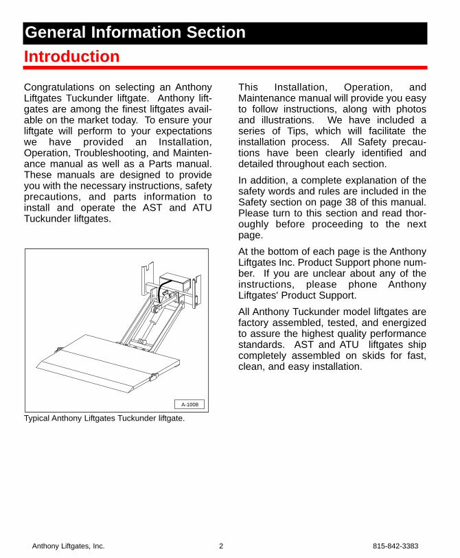
Congratulations on selecting an AnthonyLiftgates Tuckunder liftgate. Anthony lift-gates are among the finest liftgates avail-able on the market today. To ensure yourliftgate will perform to your expectationswe have provided an Installation,Operation, Troubleshooting, and Mainten-ance manual as well as a Parts manual.These manuals are designed to provideyou with the necessary instructions, safetyprecautions, and parts information toinstall and operate the AST and ATUTuckunder liftgates.
Typical Anthony Liftgates Tuckunder liftgate.
This Installation, Operation, andMaintenance manual will provide you easyto follow instructions, along with photosand illustrations. We have included aseries of Tips, which will facilitate theinstallation process. All Safety precau-tions have been clearly identified anddetailed throughout each section. In addition, a complete explanation of thesafety words and rules are included in theSafety section on page 38 of this manual.Please turn to this section and read thor-oughly before proceeding to the nextpage. At the bottom of each page is the AnthonyLiftgates Inc. Product Support phone num-ber. If you are unclear about any of theinstructions, please phone AnthonyLiftgates' Product Support.All Anthony Tuckunder model liftgates arefactory assembled, tested, and energizedto assure the highest quality performancestandards. AST and ATU liftgates shipcompletely assembled on skids for fast,clean, and easy installation.
A-1008
Anthony Liftgates, Inc. 2 815-842-3383
IntroductionGeneral Information Section

Even though the following goes with-out saying, we feel compelled to state:Anthony liftgates should only be installedby those with sufficient skills to understandthe installation and operation of the lift-gate, along with the equipment required toinstall the liftgate. The installation instruc-tions in this manual are intended to givetypical installation instructions to theinstaller for both the operation and whatwe believe to be the most desirablesequence of installation. These instruc-tions cannot replace a qualified person, orclear thinking and the basic knowledgethat must be possessed by the installer.We urge the installer (or anyone else) tocall us if they have any questions. Wehave qualified personnel at our Pontiac,Illinois, plant to answer any questions thatyou may have. A detailed discussion onthe phone can be far more satisfactorythan a detailed written explanation.It has been our experience that a knowl-edgeable journeyman following theseinstallation instructions and observing theoperation of the liftgate will have sufficientcomprehension of the liftgate to enablethis person to troubleshoot and correct allnormal problems that may be encoun-tered. However, again we urge you to callus at the Pontiac, Illinois, plant if you findthe liftgate is not operating properly or ifyou do not know how to make the neces-sary repair.
If you have any doubts or questions, callus at:Anthony Liftgates, Inc.1037 West Howard StreetPontiac, Illinois 61764(815) 842-3383www.anthonyliftgates.com
815-842-3383 3 Anthony Liftgates, Inc.
The success or failure of this lift-gate to properly and efficientlyoperate will depend on a thor-ough and proper installation.Failure to read, understand, andfollow the installation instruc-tions and safety recommenda-tions in this manual beforeinstalling the liftgate can resultin serious injury or death. Also,read and understand the operat-ing instructions in the Operationsection.
When installed, this liftgate mustnot alter nor prevent vehiclecompliance to any existing stateor federal standards, and espe-cially FMVSS 105. Each chassismanufacturer’s recommenda-tions should be consulted forcompliance. Also, make surethe weight of the liftgate and itsload will not overbalance thetruck, possibly raising the frontwheels off the ground.
DANGER
Anthony Liftgates, Inc. 4 815-842-3383
Mounting Plate
Main Platform Section
Rubber Dock BumperPad
Dock Bumper Corner Cap
Gusset
Floor Extension Assembly
Rubber Dock BumperPad
Gusset
Dock Bumper Corner Cap
Mounting Plate
A-1007
CurbsideStreetside
Flip-over Platform Section
Lift Frame
Radius Arm
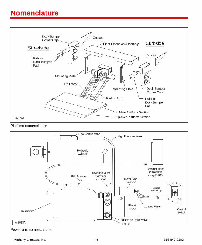
Platform nomenclature.
Nomenclature
Power unit nomenclature.
Breather Hose(all models
except 1200)
High Pressure HoseFlow Control Valve
ControlSwitch
ControlBox Wiring
ElectricMotor
PumpAdjustable Relief Valve
10 amp Fuse
Motor StartSolenoid
HydraulicCylinder
Fill / BreatherPort
Reservoir
Lowering ValveCartridgeand Coil
A-1023A
Warranty
IMPORTANT NOTICEThe liftgate must be installedaccording to the installationinstructions or the warranty willbe void. Unauthorized modifica-tions of the liftgate may cause itto improperly operate or causeother unforeseen problems ordangers. If any deviation isdeemed necessary, written per-mission must first be obtainedfrom Anthony Liftgates.
Decals
Safety decals provide a vital role in helpingto reduce injuries and/or possibly evendeath. To ensure the greatest level ofsafety, all decals must be in place and leg-ible at all times. Remember, it is the usersresponsibility to maintain these decals.For a complete part number list and illus-tration of the decals used on the AST andATU Tuckunder liftgate, refer to the Decalssection in the Parts manual.
For decal placement, refer to the Decalssection in this manual.For replacement decals contact:Anthony Liftgates, Inc.1037 West Howard StreetPontiac, Illinois 61764(815) 842-3383www.anthonyliftgates.com
Ordering PartsWe manufacturer a quality liftgate thatrequires very little maintenance or repair.However, should a part break, becomedamaged, or worn our knowledgeable staffcan make sure you receive the part(s) toput your liftgate back into operation.For questions or to order parts, contact:Anthony Liftgates, Inc.1037 West Howard StreetPontiac, Illinois 61764(815) 842-3383www.anthonyliftgates.com
Tooling RequiredThe following is a list of suggested toolsthat should be used to install theTuckunder liftgate.• Overhead Crane or Forklift• Mig or Stick Welder• Heavy-Duty C-Clamps• Tape Measure• Level (small, magnetic)• Cutting Torch (in some applications)
815-842-3383 5 Anthony Liftgates, Inc.
General Information
Make sure all decals areattached to liftgate and/or truckand are legible at all times.
DANGER
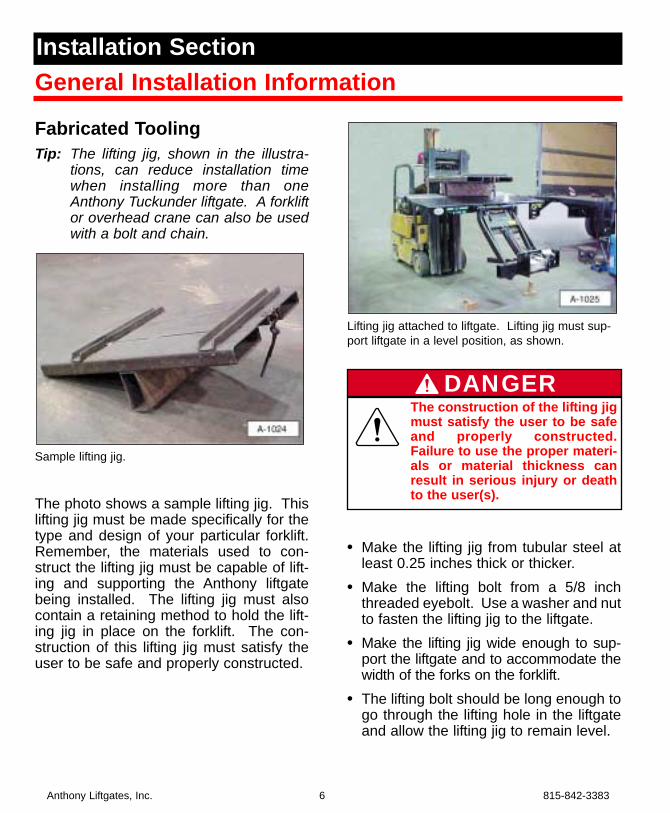
Fabricated ToolingTip: The lifting jig, shown in the illustra-
tions, can reduce installation timewhen installing more than oneAnthony Tuckunder liftgate. A forkliftor overhead crane can also be usedwith a bolt and chain.
Sample lifting jig.
The photo shows a sample lifting jig. Thislifting jig must be made specifically for thetype and design of your particular forklift.Remember, the materials used to con-struct the lifting jig must be capable of lift-ing and supporting the Anthony liftgatebeing installed. The lifting jig must alsocontain a retaining method to hold the lift-ing jig in place on the forklift. The con-struction of this lifting jig must satisfy theuser to be safe and properly constructed.
Lifting jig attached to liftgate. Lifting jig must sup-port liftgate in a level position, as shown.
• Make the lifting jig from tubular steel atleast 0.25 inches thick or thicker.
• Make the lifting bolt from a 5/8 inchthreaded eyebolt. Use a washer and nutto fasten the lifting jig to the liftgate.
• Make the lifting jig wide enough to sup-port the liftgate and to accommodate thewidth of the forks on the forklift.
• The lifting bolt should be long enough togo through the lifting hole in the liftgateand allow the lifting jig to remain level.
Anthony Liftgates, Inc. 6 815-842-3383
General Installation InformationInstallation Section
The construction of the lifting jigmust satisfy the user to be safeand properly constructed.Failure to use the proper materi-als or material thickness canresult in serious injury or deathto the user(s).
DANGER
Prior To InstallationTip: Check the OEM vehicle manual for
any special requirements prior towelding on the truck. If required, dis-connect the battery cable beforewelding on the truck.
If installing multiple liftgates, considermaking a lifting jig as shown in theFabricated Tooling section of thismanual.
1. Place the truck on a flat, level surface.Block the wheels to prevent possibletruck movement during liftgate installa-tion.
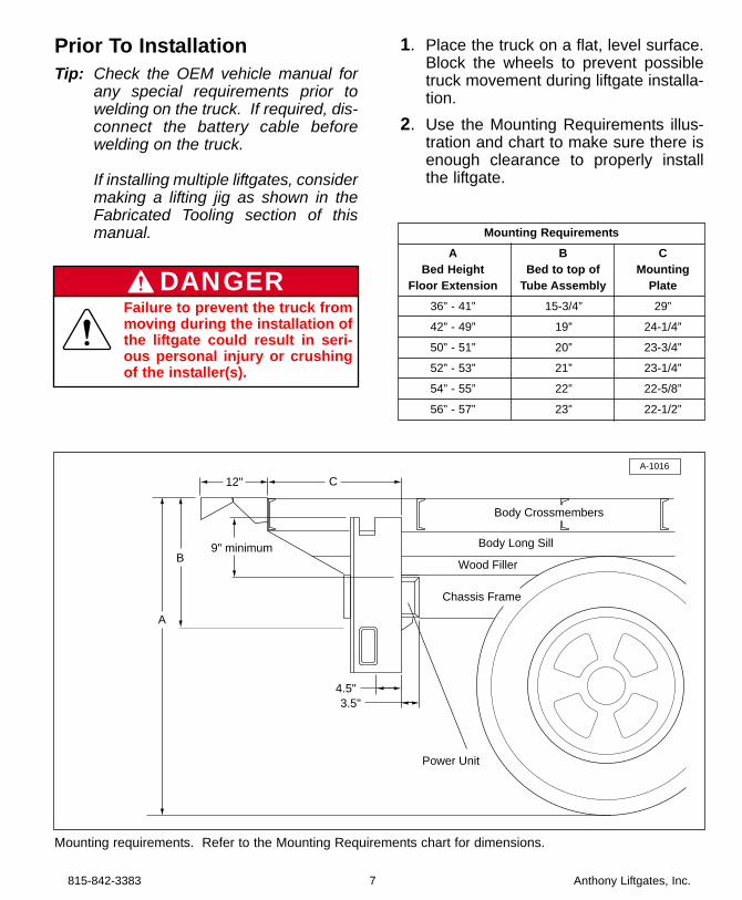
2. Use the Mounting Requirements illus-tration and chart to make sure there isenough clearance to properly installthe liftgate.
815-842-3383 7 Anthony Liftgates, Inc.
Mounting RequirementsA B C
Bed Height Bed to top of MountingFloor Extension Tube Assembly Plate
36” - 41” 15-3/4” 29”
42” - 49” 19” 24-1/4”
50” - 51” 20” 23-3/4”
52” - 53” 21” 23-1/4”
54” - 55” 22” 22-5/8”
56” - 57” 23” 22-1/2”
A
B
12" C
3.5"
9" minimum
4.5"
Body Long Sill
Wood Filler
Chassis Frame
A-1016
Power Unit
Body Crossmembers
Mounting requirements. Refer to the Mounting Requirements chart for dimensions.
Failure to prevent the truck frommoving during the installation ofthe liftgate could result in seri-ous personal injury or crushingof the installer(s).
DANGER
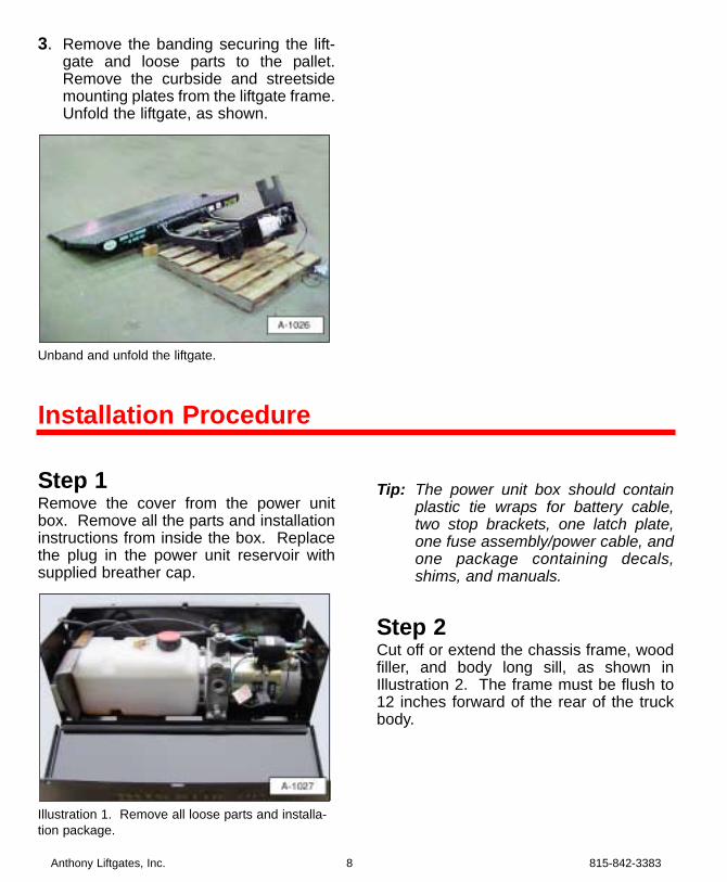
3. Remove the banding securing the lift-gate and loose parts to the pallet.Remove the curbside and streetsidemounting plates from the liftgate frame.Unfold the liftgate, as shown.
Unband and unfold the liftgate.
Step 1Remove the cover from the power unitbox. Remove all the parts and installationinstructions from inside the box. Replacethe plug in the power unit reservoir withsupplied breather cap.
Illustration 1. Remove all loose parts and installa-tion package.
Tip: The power unit box should containplastic tie wraps for battery cable,two stop brackets, one latch plate,one fuse assembly/power cable, andone package containing decals,shims, and manuals.
Step 2Cut off or extend the chassis frame, woodfiller, and body long sill, as shown inIllustration 2. The frame must be flush to12 inches forward of the rear of the truckbody.
Anthony Liftgates, Inc. 8 815-842-3383
Installation Procedure
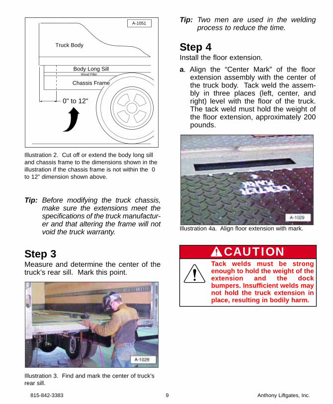
Illustration 2. Cut off or extend the body long silland chassis frame to the dimensions shown in theillustration if the chassis frame is not within the 0to 12” dimension shown above.
Tip: Before modifying the truck chassis,make sure the extensions meet thespecifications of the truck manufactur-er and that altering the frame will notvoid the truck warranty.
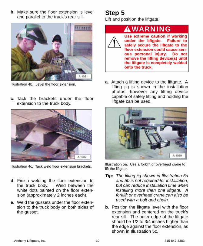
Step 3Measure and determine the center of thetruck’s rear sill. Mark this point.
Illustration 3. Find and mark the center of truck’srear sill.
Tip: Two men are used in the weldingprocess to reduce the time.
Step 4Install the floor extension.a. Align the “Center Mark” of the floor
extension assembly with the center ofthe truck body. Tack weld the assem-bly in three places (left, center, andright) level with the floor of the truck.The tack weld must hold the weight ofthe floor extension, approximately 200pounds.
Illustration 4a. Align floor extension with mark.
0" to 12"
Body Long SillWood Filler
Chassis Frame
A-1051
Truck Body
815-842-3383 9 Anthony Liftgates, Inc.
Tack welds must be strongenough to hold the weight of theextension and the dockbumpers. Insufficient welds maynot hold the truck extension inplace, resulting in bodily harm.
CAUTION
b. Make sure the floor extension is leveland parallel to the truck’s rear sill.
Illustration 4b. Level the floor extension.
c. Tack the brackets under the floorextension to the truck body.
Illustration 4c. Tack weld floor extension brackets.
d. Finish welding the floor extension tothe truck body. Weld between thewhite dots painted on the floor exten-sion (approximately 2 inches each).
e. Weld the gussets under the floor exten-sion to the truck body on both sides ofthe gusset.
Step 5Lift and position the liftgate.
a. Attach a lifting device to the liftgate. Alifting jig is shown in the installationphotos, however any lifting devicecapable of safely lifting and holding theliftgate can be used.
Illustration 5a. Use a forklift or overhead crane tolift the liftgate.
Tip: The lifting jig shown in Illustration 5aand 5b is not required for installation,but can reduce installation time wheninstalling more than one liftgate. Aforklift or overhead crane can also beused with a bolt and chain.
b. Position the liftgate level with the floorextension and centered on the truck’srear sill. The outer edge of the liftgateshould be 1/2 to 3/4 inches higher thanthe edge against the floor extension, asshown in Illustration 5c.
Anthony Liftgates, Inc. 10 815-842-3383
Use extreme caution if workingunder the liftgate. Failure tosafely secure the liftgate to thefloor extension could cause seri-ous personal injury. Do notremove the lifting device(s) untilthe liftgate is completely weldedonto the truck.
WARNING
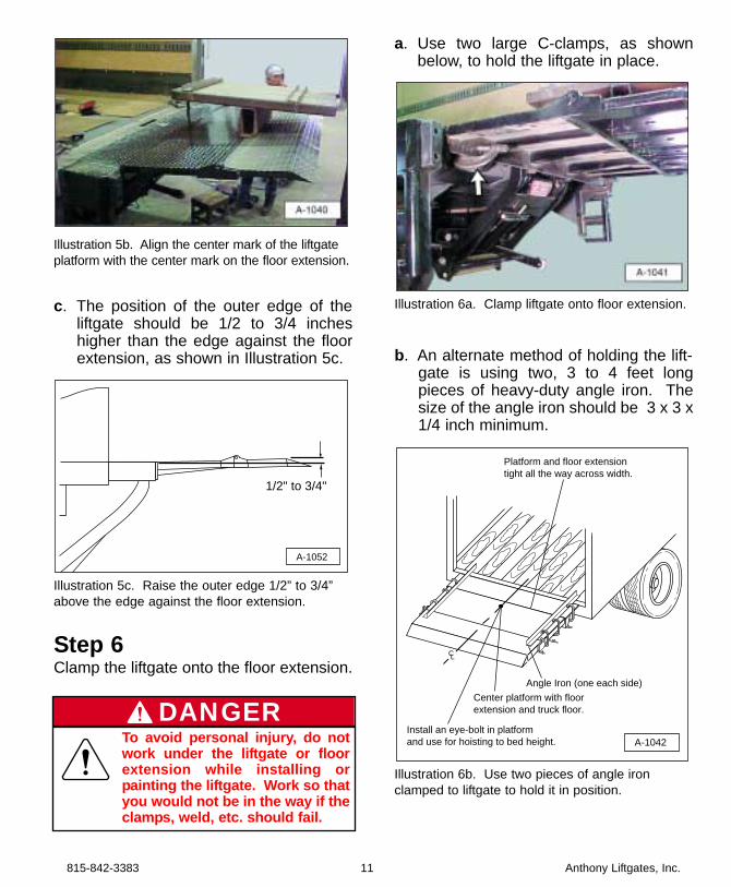
Illustration 5b. Align the center mark of the liftgateplatform with the center mark on the floor extension.
c. The position of the outer edge of theliftgate should be 1/2 to 3/4 incheshigher than the edge against the floorextension, as shown in Illustration 5c.
Illustration 5c. Raise the outer edge 1/2” to 3/4”above the edge against the floor extension.
Step 6Clamp the liftgate onto the floor extension.
a. Use two large C-clamps, as shownbelow, to hold the liftgate in place.
Illustration 6a. Clamp liftgate onto floor extension.
b. An alternate method of holding the lift-gate is using two, 3 to 4 feet longpieces of heavy-duty angle iron. Thesize of the angle iron should be 3 x 3 x1/4 inch minimum.
Illustration 6b. Use two pieces of angle ironclamped to liftgate to hold it in position.
CL
A-1042
Platform and floor extensiontight all the way across width.
Angle Iron (one each side)
Center platform with floorextension and truck floor.
Install an eye-bolt in platformand use for hoisting to bed height.
1/2" to 3/4"
A-1052
815-842-3383 11 Anthony Liftgates, Inc.
To avoid personal injury, do notwork under the liftgate or floorextension while installing orpainting the liftgate. Work so thatyou would not be in the way if theclamps, weld, etc. should fail.
DANGER
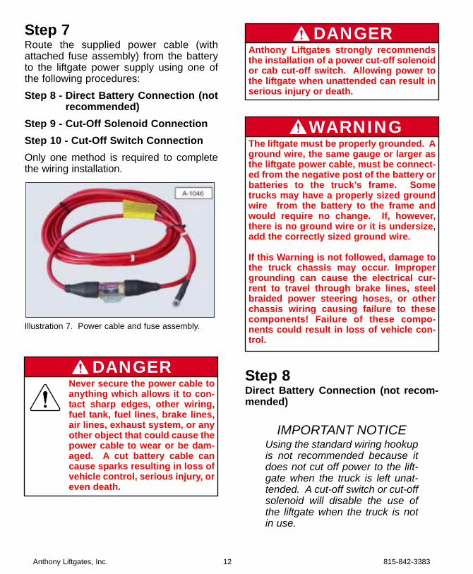
Step 7Route the supplied power cable (withattached fuse assembly) from the batteryto the liftgate power supply using one ofthe following procedures:Step 8 - Direct Battery Connection (not
recommended)Step 9 - Cut-Off Solenoid ConnectionStep 10 - Cut-Off Switch ConnectionOnly one method is required to completethe wiring installation.
Illustration 7. Power cable and fuse assembly.
Step 8Direct Battery Connection (not recom-mended)
IMPORTANT NOTICEUsing the standard wiring hookupis not recommended because itdoes not cut off power to the lift-gate when the truck is left unat-tended. A cut-off switch or cut-offsolenoid will disable the use ofthe liftgate when the truck is notin use.
Anthony Liftgates, Inc. 12 815-842-3383
Never secure the power cable toanything which allows it to con-tact sharp edges, other wiring,fuel tank, fuel lines, brake lines,air lines, exhaust system, or anyother object that could cause thepower cable to wear or be dam-aged. A cut battery cable cancause sparks resulting in loss ofvehicle control, serious injury, oreven death.
DANGER
The liftgate must be properly grounded. Aground wire, the same gauge or larger asthe liftgate power cable, must be connect-ed from the negative post of the battery orbatteries to the truck’s frame. Sometrucks may have a properly sized groundwire from the battery to the frame andwould require no change. If, however,there is no ground wire or it is undersize,add the correctly sized ground wire.
If this Warning is not followed, damage tothe truck chassis may occur. Impropergrounding can cause the electrical cur-rent to travel through brake lines, steelbraided power steering hoses, or otherchassis wiring causing failure to thesecomponents! Failure of these compo-nents could result in loss of vehicle con-trol.
WARNING
Anthony Liftgates strongly recommendsthe installation of a power cut-off solenoidor cab cut-off switch. Allowing power tothe liftgate when unattended can result inserious injury or death.
DANGER
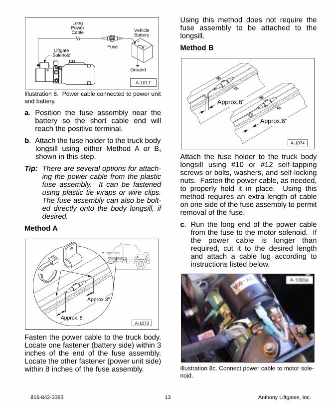
Illustration 8. Power cable connected to power unitand battery.
a. Position the fuse assembly near thebattery so the short cable end willreach the positive terminal.
b. Attach the fuse holder to the truck bodylongsill using either Method A or B,shown in this step.
Tip: There are several options for attach-ing the power cable from the plasticfuse assembly. It can be fastenedusing plastic tie wraps or wire clips.The fuse assembly can also be bolt-ed directly onto the body longsill, ifdesired.
Method A
Fasten the power cable to the truck body.Locate one fastener (battery side) within 3inches of the end of the fuse assembly.Locate the other fastener (power unit side)within 8 inches of the fuse assembly.
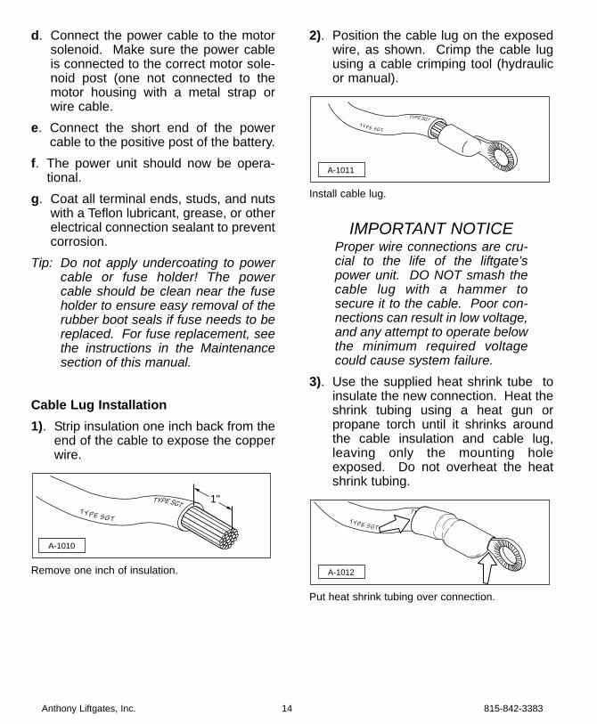
Using this method does not require thefuse assembly to be attached to thelongsill.Method B
Attach the fuse holder to the truck bodylongsill using #10 or #12 self-tappingscrews or bolts, washers, and self-lockingnuts. Fasten the power cable, as needed,to properly hold it in place. Using thismethod requires an extra length of cableon one side of the fuse assembly to permitremoval of the fuse.c. Run the long end of the power cable
from the fuse to the motor solenoid. Ifthe power cable is longer thanrequired, cut it to the desired lengthand attach a cable lug according toinstructions listed below.
Illustration 8c. Connect power cable to motor sole-noid.
A-1074
Approx.6"
Approx.6"
A-1073
TO LIFTGATE
Approx. 8"
Approx.3"
+–
LongPowerCable
Fuse
Ground
VehicleBattery
A-1017
LiftgateSolenoid
815-842-3383 13 Anthony Liftgates, Inc.
d. Connect the power cable to the motorsolenoid. Make sure the power cableis connected to the correct motor sole-noid post (one not connected to themotor housing with a metal strap orwire cable.
e. Connect the short end of the powercable to the positive post of the battery.
f. The power unit should now be opera-tional.
g. Coat all terminal ends, studs, and nutswith a Teflon lubricant, grease, or otherelectrical connection sealant to preventcorrosion.
Tip: Do not apply undercoating to powercable or fuse holder! The powercable should be clean near the fuseholder to ensure easy removal of therubber boot seals if fuse needs to bereplaced. For fuse replacement, seethe instructions in the Maintenancesection of this manual.
Cable Lug Installation1). Strip insulation one inch back from the
end of the cable to expose the copperwire.
Remove one inch of insulation.
2). Position the cable lug on the exposedwire, as shown. Crimp the cable lugusing a cable crimping tool (hydraulicor manual).
Install cable lug.
IMPORTANT NOTICEProper wire connections are cru-cial to the life of the liftgate’spower unit. DO NOT smash thecable lug with a hammer tosecure it to the cable. Poor con-nections can result in low voltage,and any attempt to operate belowthe minimum required voltagecould cause system failure.
3). Use the supplied heat shrink tube toinsulate the new connection. Heat theshrink tubing using a heat gun orpropane torch until it shrinks aroundthe cable insulation and cable lug,leaving only the mounting holeexposed. Do not overheat the heatshrink tubing.
Put heat shrink tubing over connection.
A-1012
TYPE SGT
TYPE SGT
A-1011
TYPE SGT
TYPE SGT
TYPE SGT
TYPE SGT
A-1010
1"
Anthony Liftgates, Inc. 14 815-842-3383
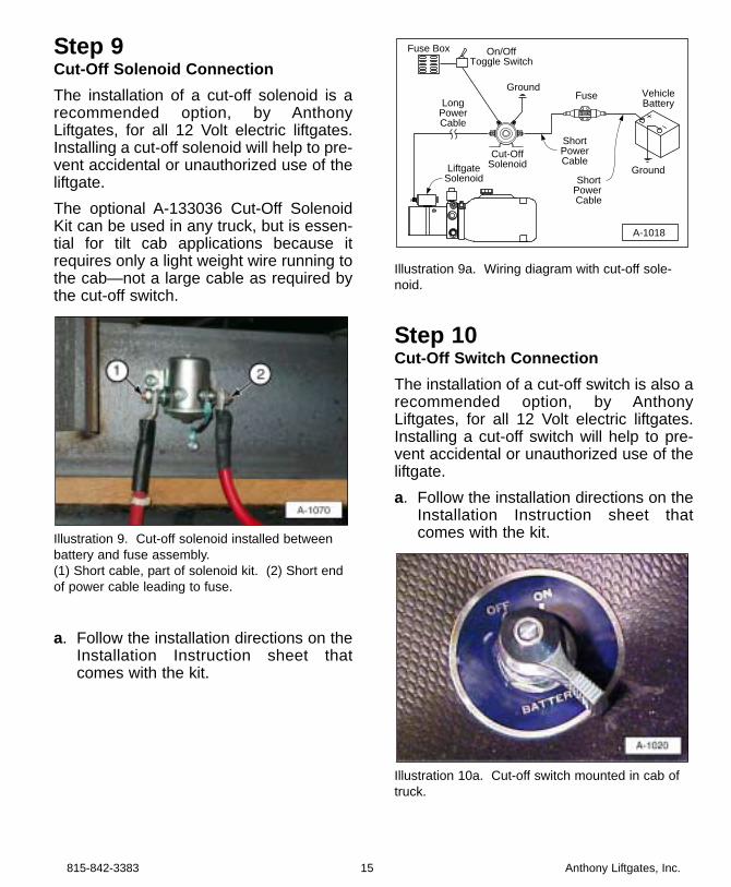
Step 9Cut-Off Solenoid ConnectionThe installation of a cut-off solenoid is arecommended option, by AnthonyLiftgates, for all 12 Volt electric liftgates.Installing a cut-off solenoid will help to pre-vent accidental or unauthorized use of theliftgate.The optional A-133036 Cut-Off SolenoidKit can be used in any truck, but is essen-tial for tilt cab applications because itrequires only a light weight wire running tothe cab—not a large cable as required bythe cut-off switch.
Illustration 9. Cut-off solenoid installed betweenbattery and fuse assembly.(1) Short cable, part of solenoid kit. (2) Short endof power cable leading to fuse.
a. Follow the installation directions on theInstallation Instruction sheet thatcomes with the kit.
Illustration 9a. Wiring diagram with cut-off sole-noid.
Step 10Cut-Off Switch ConnectionThe installation of a cut-off switch is also arecommended option, by AnthonyLiftgates, for all 12 Volt electric liftgates.Installing a cut-off switch will help to pre-vent accidental or unauthorized use of theliftgate.a. Follow the installation directions on the
Installation Instruction sheet thatcomes with the kit.
Illustration 10a. Cut-off switch mounted in cab oftruck.
+–
Ground
A-1018
LongPowerCable
ShortPowerCable
ShortPower Cable
Fuse VehicleBattery
Ground
Cut-OffSolenoid
Fuse Box On/OffToggle Switch
LiftgateSolenoid
815-842-3383 15 Anthony Liftgates, Inc.
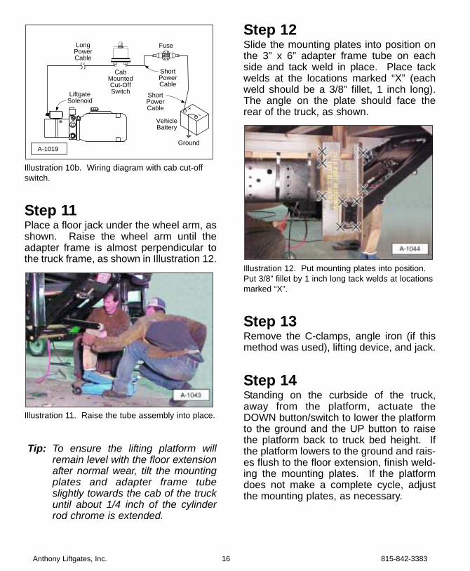
Illustration 10b. Wiring diagram with cab cut-offswitch.
Step 11Place a floor jack under the wheel arm, asshown. Raise the wheel arm until theadapter frame is almost perpendicular tothe truck frame, as shown in Illustration 12.
Illustration 11. Raise the tube assembly into place.
Tip: To ensure the lifting platform willremain level with the floor extensionafter normal wear, tilt the mountingplates and adapter frame tubeslightly towards the cab of the truckuntil about 1/4 inch of the cylinderrod chrome is extended.
Step 12Slide the mounting plates into position onthe 3” x 6” adapter frame tube on eachside and tack weld in place. Place tackwelds at the locations marked “X” (eachweld should be a 3/8” fillet, 1 inch long).The angle on the plate should face therear of the truck, as shown.
Illustration 12. Put mounting plates into position.Put 3/8” fillet by 1 inch long tack welds at locationsmarked “X”.
Step 13Remove the C-clamps, angle iron (if thismethod was used), lifting device, and jack.
Step 14Standing on the curbside of the truck,away from the platform, actuate theDOWN button/switch to lower the platformto the ground and the UP button to raisethe platform back to truck bed height. Ifthe platform lowers to the ground and rais-es flush to the floor extension, finish weld-ing the mounting plates. If the platformdoes not make a complete cycle, adjustthe mounting plates, as necessary.
A-1019
+–
LongPowerCable
Fuse
Ground
VehicleBattery
CabMountedCut-OffSwitch
ShortPowerCable
ShortPowerCable
LiftgateSolenoid
Anthony Liftgates, Inc. 16 815-842-3383
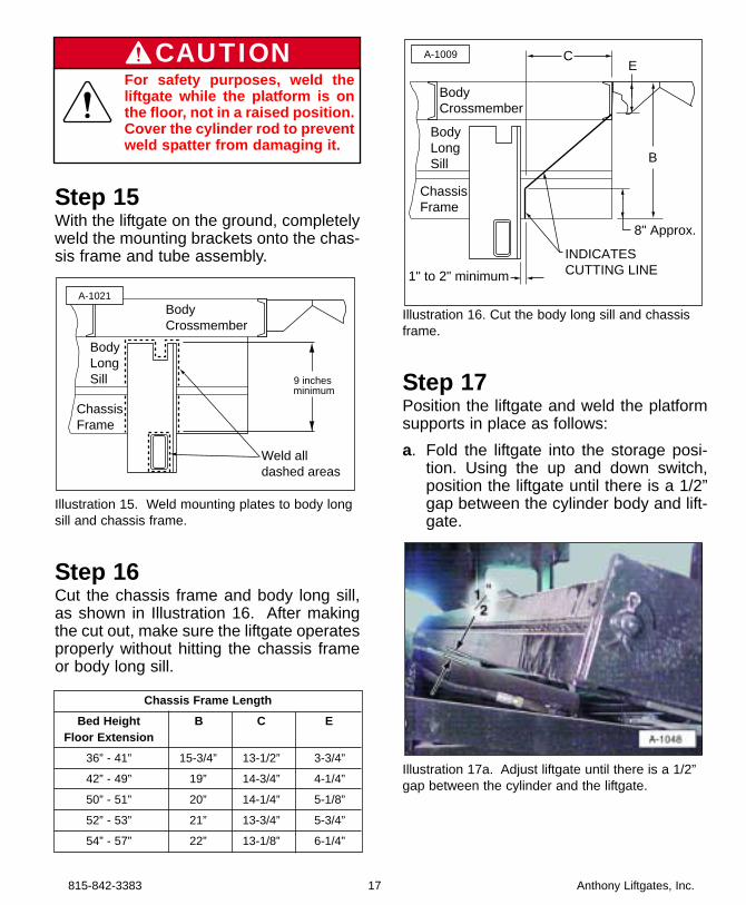
Step 15With the liftgate on the ground, completelyweld the mounting brackets onto the chas-sis frame and tube assembly.
Illustration 15. Weld mounting plates to body longsill and chassis frame.
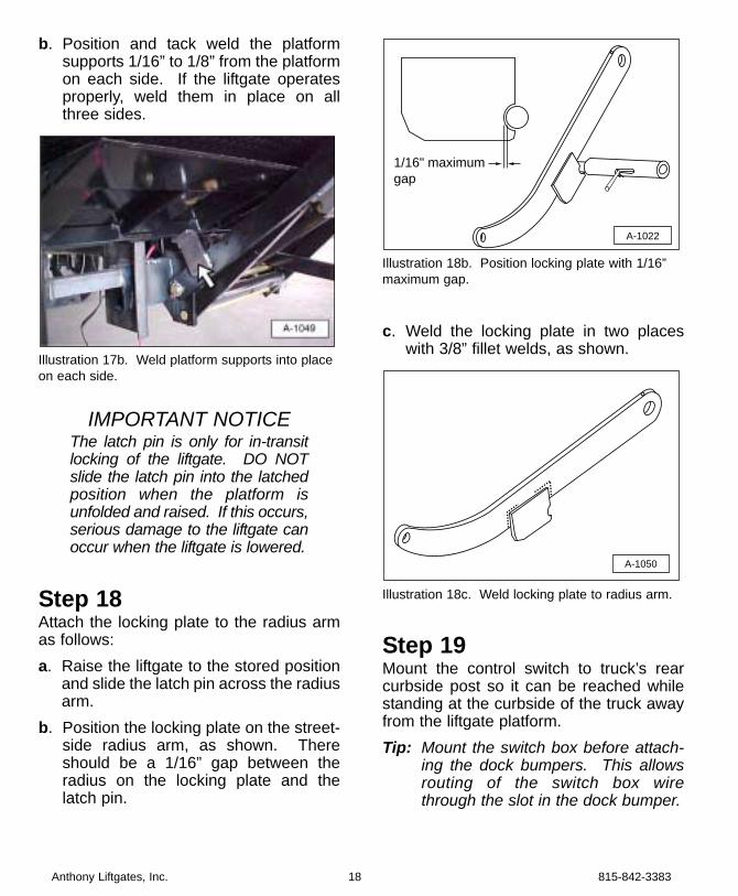
Step 16Cut the chassis frame and body long sill,as shown in Illustration 16. After makingthe cut out, make sure the liftgate operatesproperly without hitting the chassis frameor body long sill.
Illustration 16. Cut the body long sill and chassisframe.
Step 17Position the liftgate and weld the platformsupports in place as follows:a. Fold the liftgate into the storage posi-
tion. Using the up and down switch,position the liftgate until there is a 1/2”gap between the cylinder body and lift-gate.
Illustration 17a. Adjust liftgate until there is a 1/2”gap between the cylinder and the liftgate.
INDICATESCUTTING LINE
C
B
ChassisFrame
BodyLongSill
E
BodyCrossmember
1" to 2" minimum
A-1009
8" Approx.
ChassisFrame
BodyLongSill
BodyCrossmember
Weld all dashed areas
9 inches minimum
A-1021
815-842-3383 17 Anthony Liftgates, Inc.
For safety purposes, weld theliftgate while the platform is onthe floor, not in a raised position.Cover the cylinder rod to preventweld spatter from damaging it.
CAUTION
Chassis Frame LengthBed Height B C E
Floor Extension36” - 41” 15-3/4” 13-1/2” 3-3/4”
42” - 49” 19” 14-3/4” 4-1/4”
50” - 51” 20” 14-1/4” 5-1/8”
52” - 53” 21” 13-3/4” 5-3/4”
54” - 57” 22” 13-1/8” 6-1/4”
b. Position and tack weld the platformsupports 1/16” to 1/8” from the platformon each side. If the liftgate operatesproperly, weld them in place on allthree sides.
Illustration 17b. Weld platform supports into placeon each side.
IMPORTANT NOTICEThe latch pin is only for in-transitlocking of the liftgate. DO NOTslide the latch pin into the latchedposition when the platform isunfolded and raised. If this occurs,serious damage to the liftgate canoccur when the liftgate is lowered.
Step 18Attach the locking plate to the radius armas follows:a. Raise the liftgate to the stored position
and slide the latch pin across the radiusarm.
b. Position the locking plate on the street-side radius arm, as shown. Thereshould be a 1/16” gap between theradius on the locking plate and thelatch pin.
Illustration 18b. Position locking plate with 1/16”maximum gap.
c. Weld the locking plate in two placeswith 3/8” fillet welds, as shown.
Illustration 18c. Weld locking plate to radius arm.
Step 19Mount the control switch to truck’s rearcurbside post so it can be reached whilestanding at the curbside of the truck awayfrom the liftgate platform.Tip: Mount the switch box before attach-
ing the dock bumpers. This allowsrouting of the switch box wirethrough the slot in the dock bumper.
A-1050
A-1022
1/16" maximum gap
Anthony Liftgates, Inc. 18 815-842-3383
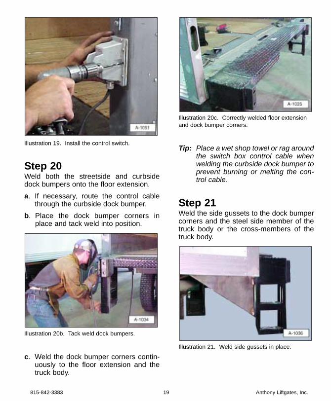
Illustration 19. Install the control switch.
Step 20Weld both the streetside and curbsidedock bumpers onto the floor extension.a. If necessary, route the control cable
through the curbside dock bumper.b. Place the dock bumper corners in
place and tack weld into position.
Illustration 20b. Tack weld dock bumpers.
c. Weld the dock bumper corners contin-uously to the floor extension and thetruck body.
Illustration 20c. Correctly welded floor extensionand dock bumper corners.
Tip: Place a wet shop towel or rag aroundthe switch box control cable whenwelding the curbside dock bumper toprevent burning or melting the con-trol cable.
Step 21Weld the side gussets to the dock bumpercorners and the steel side member of thetruck body or the cross-members of thetruck body.
Illustration 21. Weld side gussets in place.
815-842-3383 19 Anthony Liftgates, Inc.
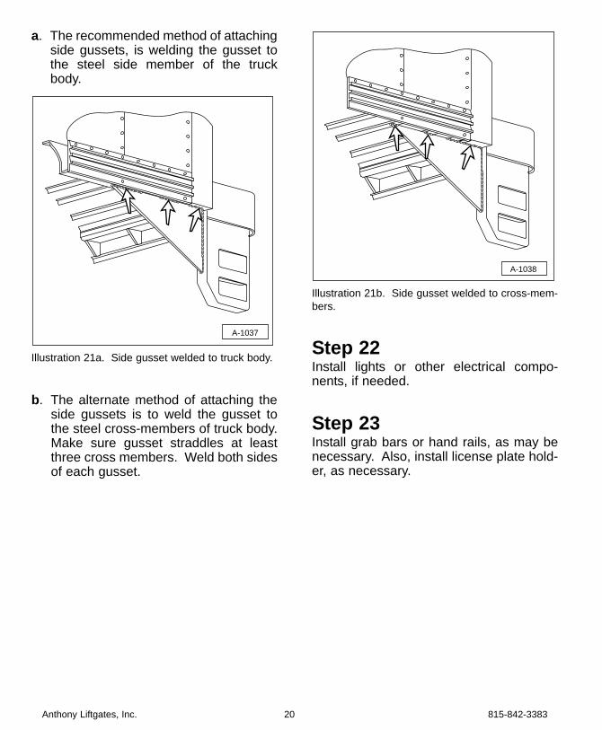
a. The recommended method of attachingside gussets, is welding the gusset tothe steel side member of the truckbody.
Illustration 21a. Side gusset welded to truck body.
b. The alternate method of attaching theside gussets is to weld the gusset tothe steel cross-members of truck body.Make sure gusset straddles at leastthree cross members. Weld both sidesof each gusset.
Illustration 21b. Side gusset welded to cross-mem-bers.
Step 22Install lights or other electrical compo-nents, if needed.
Step 23Install grab bars or hand rails, as may benecessary. Also, install license plate hold-er, as necessary.
A-1038
A-1037
Anthony Liftgates, Inc. 20 815-842-3383
IMPORTANT NOTICESome models of Anthony liftgatesmay be provided with stepdevices to assist in the ingress oregress of the rear of the truck ortrailer. These devices are NOT tobe considered all inclusive of anyrequirements or guidelinesregarding proper ingress oregress of trucks and trailers.These items are provided only asan added feature for installers tohelp simplify the meeting of pos-sible ingress or egress require-ments. As there are many vari-ables in truck sizes and shapes, itis the installers responsibility todetermine proper ingress andegress requirements, such assteps, hand grips, grab bars, etc.for each vehicle receiving anAnthony liftgate.
Step 24Make a final operation check.a. Make sure the platform will travel
through a complete cycle, up anddown, smoothly and freely, with theplatform completely open.
b. Make sure the platform will fold andtuck under the truck in a stored posi-tion, and latch. The liftgate must foldsmoothly and freely.
c. Make sure hydraulic hose fittings aretight and hydraulic hose does not rubagainst the liftgate or other parts whilecycling up, down, open, and closed.Adjust as necessary by loosening fittingsand adjusting the position of the hose(s).Retighten fittings.
Step 25Attach all decals, as shown in the Decalsection of this manual.
Step 26Complete the Final Inspection Checklistsection.
815-842-3383 21 Anthony Liftgates, Inc.
❏❏ Check all welds to make sure they aredone properly.
❏❏ Make sure all pins are in place and heldwith proper retainers.
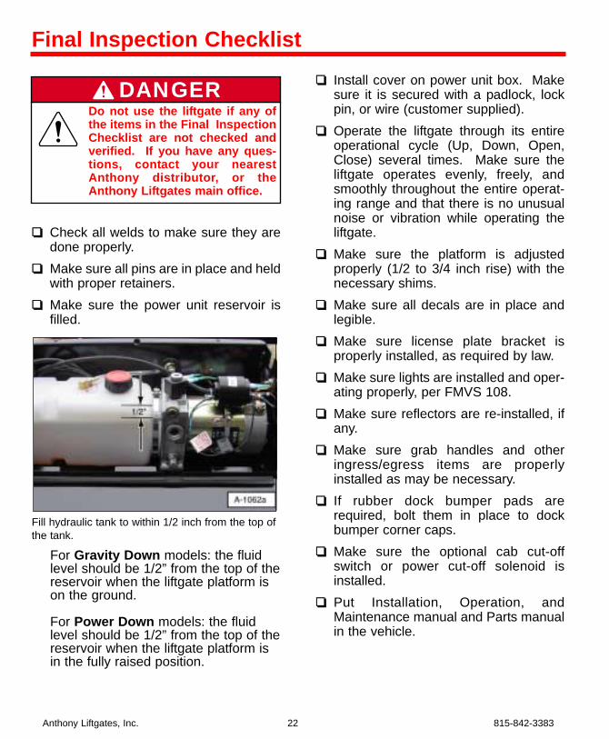
❏❏ Make sure the power unit reservoir isfilled.
Fill hydraulic tank to within 1/2 inch from the top ofthe tank.
For Gravity Down models: the fluidlevel should be 1/2” from the top of thereservoir when the liftgate platform ison the ground.
For Power Down models: the fluidlevel should be 1/2” from the top of thereservoir when the liftgate platform isin the fully raised position.
❏❏ Install cover on power unit box. Makesure it is secured with a padlock, lockpin, or wire (customer supplied).
❏❏ Operate the liftgate through its entireoperational cycle (Up, Down, Open,Close) several times. Make sure theliftgate operates evenly, freely, andsmoothly throughout the entire operat-ing range and that there is no unusualnoise or vibration while operating theliftgate.
❏❏ Make sure the platform is adjustedproperly (1/2 to 3/4 inch rise) with thenecessary shims.
❏❏ Make sure all decals are in place andlegible.
❏❏ Make sure license plate bracket isproperly installed, as required by law.
❏❏ Make sure lights are installed and oper-ating properly, per FMVS 108.
❏❏ Make sure reflectors are re-installed, ifany.
❏❏ Make sure grab handles and otheringress/egress items are properlyinstalled as may be necessary.
❏❏ If rubber dock bumper pads arerequired, bolt them in place to dockbumper corner caps.
❏❏ Make sure the optional cab cut-offswitch or power cut-off solenoid isinstalled.
❏❏ Put Installation, Operation, andMaintenance manual and Parts manualin the vehicle.
Anthony Liftgates, Inc. 22 815-842-3383
Final Inspection Checklist
Do not use the liftgate if any ofthe items in the Final InspectionChecklist are not checked andverified. If you have any ques-tions, contact your nearestAnthony distributor, or theAnthony Liftgates main office.
DANGER
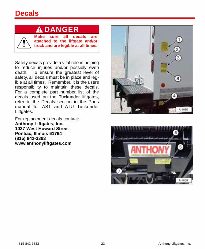
Safety decals provide a vital role in helpingto reduce injuries and/or possibly evendeath. To ensure the greatest level ofsafety, all decals must be in place and leg-ible at all times. Remember, it is the usersresponsibility to maintain these decals.For a complete part number list of thedecals used on the Tuckunder liftgates,refer to the Decals section in the Partsmanual for AST and ATU TuckunderLiftgates.For replacement decals contact: Anthony Liftgates, Inc.1037 West Howard StreetPontiac, Illinois 61764(815) 842-3383www.anthonyliftgates.com
815-842-3383 23 Anthony Liftgates, Inc.
Decals
Make sure all decals areattached to the liftgate and/ortruck and are legible at all times.
DANGER
Anthony Liftgates, Inc. 24 815-842-3383
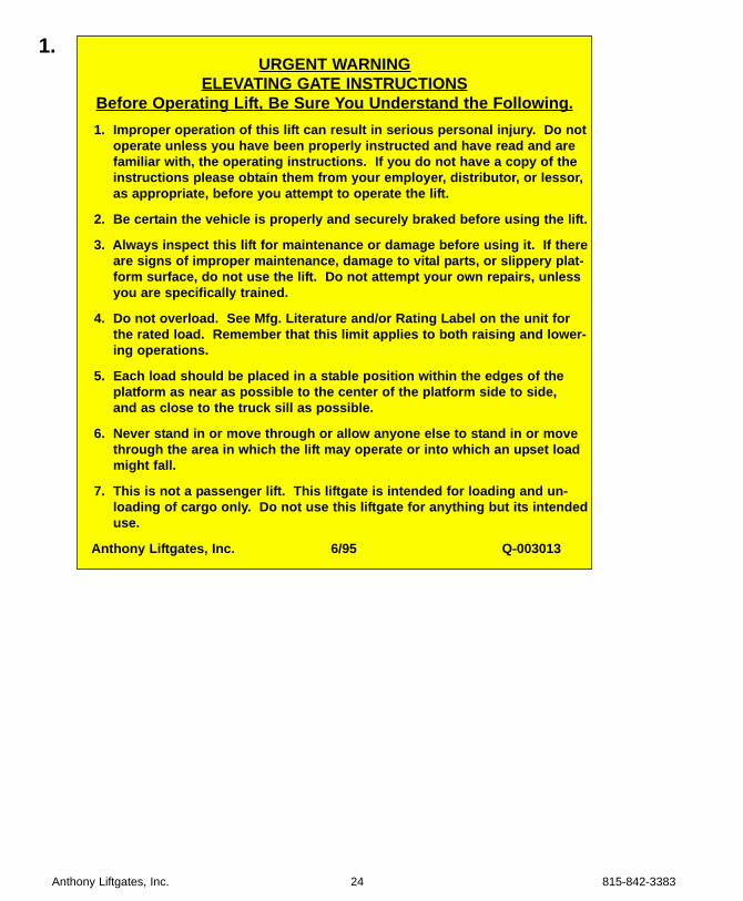
1.URGENT WARNING
ELEVATING GATE INSTRUCTIONSBefore Operating Lift, Be Sure You Understand the Following.1. Improper operation of this lift can result in serious personal injury. Do not
operate unless you have been properly instructed and have read and arefamiliar with, the operating instructions. If you do not have a copy of theinstructions please obtain them from your employer, distributor, or lessor,as appropriate, before you attempt to operate the lift.
2. Be certain the vehicle is properly and securely braked before using the lift.
3. Always inspect this lift for maintenance or damage before using it. If thereare signs of improper maintenance, damage to vital parts, or slippery plat-form surface, do not use the lift. Do not attempt your own repairs, unless you are specifically trained.
4. Do not overload. See Mfg. Literature and/or Rating Label on the unit forthe rated load. Remember that this limit applies to both raising and lower-ing operations.
5. Each load should be placed in a stable position within the edges of theplatform as near as possible to the center of the platform side to side, and as close to the truck sill as possible.
6. Never stand in or move through or allow anyone else to stand in or movethrough the area in which the lift may operate or into which an upset loadmight fall.
7. This is not a passenger lift. This liftgate is intended for loading and un-loading of cargo only. Do not use this liftgate for anything but its intendeduse.
Anthony Liftgates, Inc. 6/95 Q-003013
815-842-3383 25 Anthony Liftgates, Inc.
2.
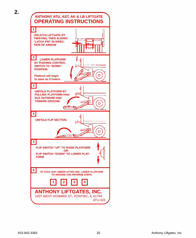
UNLATCH LIFTGATE BYTWISTING, THEN SLIDING“LATCH PIN” IN DIREC-TION OF ARROW
ANTHONY ATU, AST, AK & LB LIFTGATEOPERATING INSTRUCTIONS
LOWER PLATFORMBY PUSHING CONTROLSWITCH TO “DOWN”POSITION
Platform will begin to open as it lowers.
UNFOLD PLATFORM BYPULLING PLATFORM HAN-DLE OUTWARD ANDTOWARD GROUND.
UNFOLD FLIP SECTION.
FLIP SWITCH “UP” TO RAISE PLATFORM-OR-
FLIP SWITCH “DOWN” TO LOWER PLAT-FORM
TO TUCK UNIT UNDER AFTER USE, LOWER PLATFORMTO GROUND AND REVERSE STEPS
1 432
6
5
4
3
2
1
ANTHONY LIFTGATES, INC.1037 WEST HOWARD ST., PONTIAC, IL 61764
ATU-423
Anthony Liftgates, Inc. 26 815-842-3383
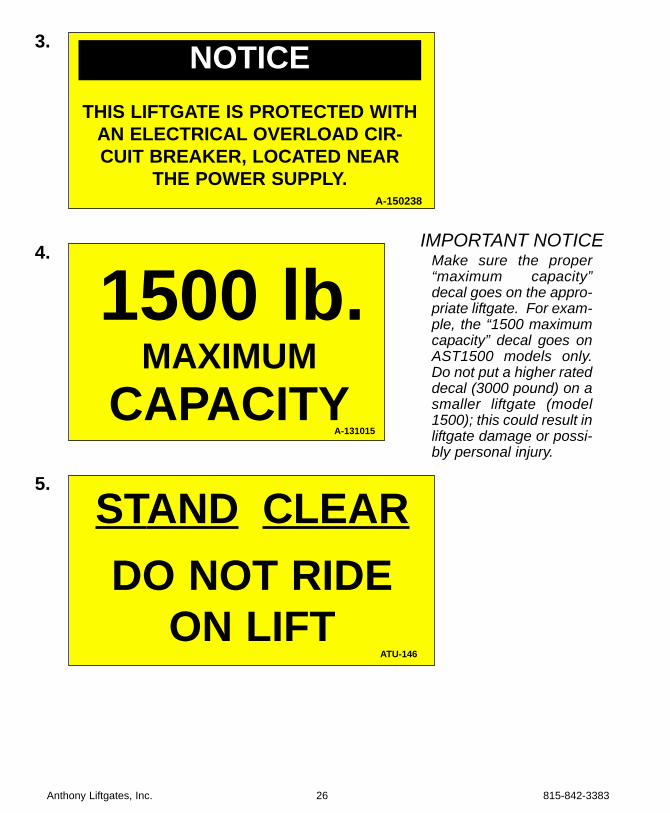
MAXIMUMCAPACITY
1500 lb.
THIS LIFTGATE IS PROTECTED WITHAN ELECTRICAL OVERLOAD CIR-CUIT BREAKER, LOCATED NEAR
THE POWER SUPPLY.
NOTICE3.
4.
STAND CLEARDO NOT RIDE
ON LIFT
5.
IMPORTANT NOTICEMake sure the proper“maximum capacity”decal goes on the appro-priate liftgate. For exam-ple, the “1500 maximumcapacity” decal goes onAST1500 models only.Do not put a higher rateddecal (3000 pound) on asmaller liftgate (model1500); this could result inliftgate damage or possi-bly personal injury.
A-150238
A-131015
ATU-146
815-842-3383 27 Anthony Liftgates, Inc.
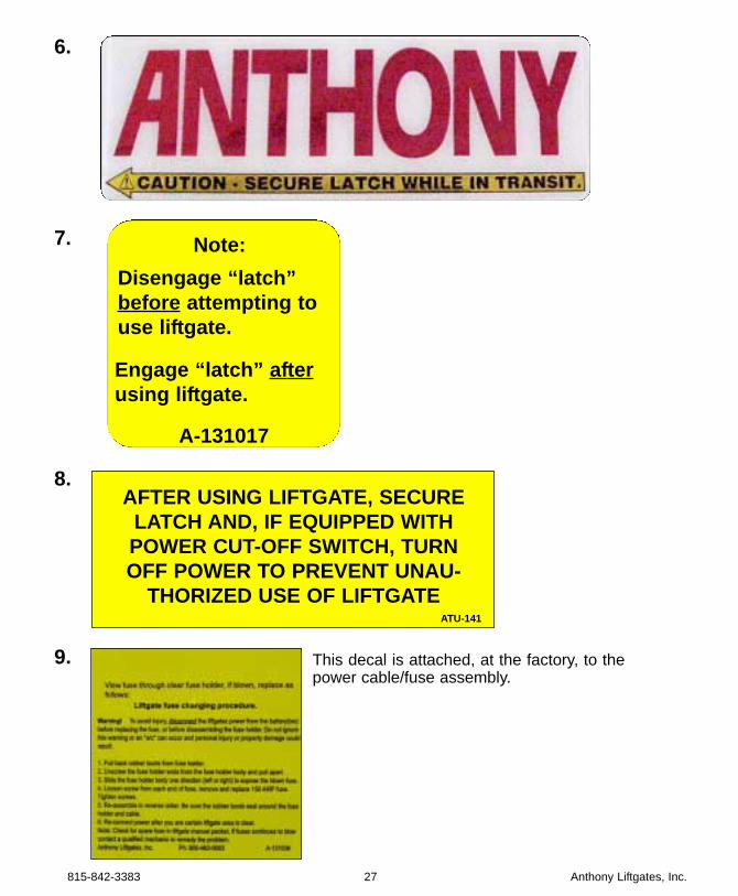
AFTER USING LIFTGATE, SECURELATCH AND, IF EQUIPPED WITHPOWER CUT-OFF SWITCH, TURNOFF POWER TO PREVENT UNAU-
THORIZED USE OF LIFTGATE
6.
8.
7. Note:Disengage “latch”before attempting touse liftgate.
Engage “latch” afterusing liftgate.
A-131017
ATU-141
9. This decal is attached, at the factory, to thepower cable/fuse assembly.
The following is a list of Do’s and Don’ts forthe operation of the liftgate.
✔✔ Do’s✔ Read and follow warning decals, oper-
ating decals, and owners manual.✔ Keep all decals in place and legible and
retain the owners manual in the vehicleor all Warranties are void.
✔ Make sure the vehicle is properly andsecurely braked before using the lift-gate.
✔ Keep yourself clear of all moving parts.✔ Make sure the area in which the plat-
form will open and close is clear beforeopening, closing, raising, or loweringthe platform.
✔ Make sure the platform area, includingthe area in which loads may fall from theplatform, is clear before, during, and atall times while operating the liftgate.
✔ Always place the load as close to thecenter of the platform as possible. Also,position the load as close to the centerof the truck’s rear sill as possible.
✔ Only operate the liftgate with the pushbutton/switch controls mounted on thetruck body.
✔ Check the oil level in the hydraulicreservoir monthly. Change it if it is con-taminated or dirty.
✔ Visually inspect your liftgate frequentlyand keep it properly adjusted.
✔ Repair any damage to the liftgate to pre-vent accidents.
✔ Lock the liftgate into the storage posi-tion with the latch pin when the liftgate isnot in use.
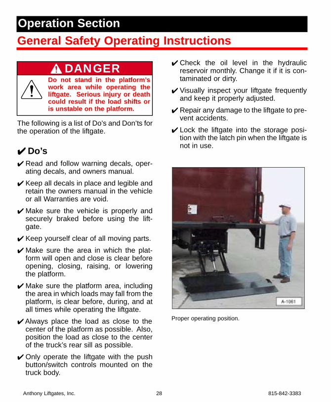
Proper operating position.
Anthony Liftgates, Inc. 28 815-842-3383
General Safety Operating InstructionsOperation Section
Do not stand in the platform’swork area while operating theliftgate. Serious injury or deathcould result if the load shifts oris unstable on the platform.
DANGER
✘✘ Don’ts
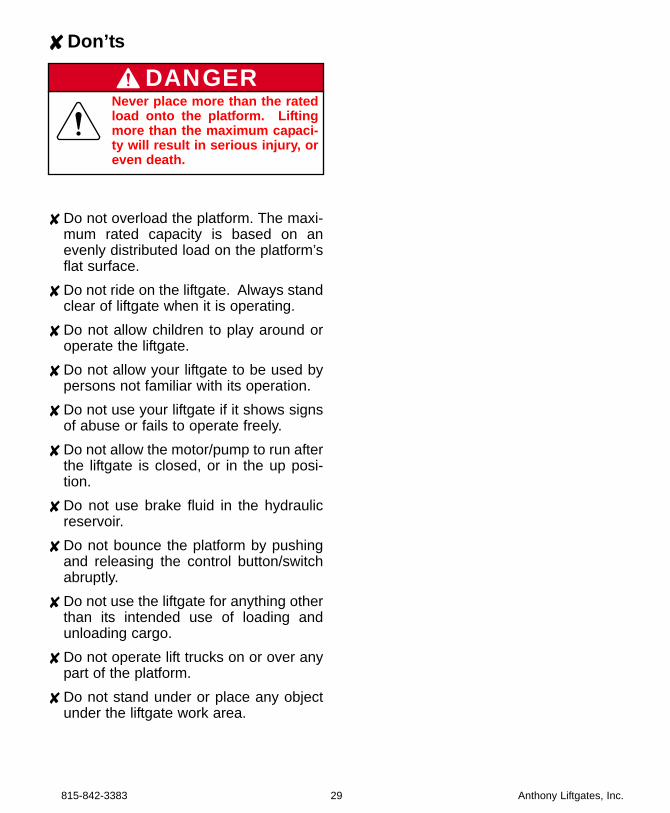
✘ Do not overload the platform. The maxi-mum rated capacity is based on anevenly distributed load on the platform’sflat surface.
✘ Do not ride on the liftgate. Always standclear of liftgate when it is operating.
✘ Do not allow children to play around oroperate the liftgate.
✘ Do not allow your liftgate to be used bypersons not familiar with its operation.
✘ Do not use your liftgate if it shows signsof abuse or fails to operate freely.
✘ Do not allow the motor/pump to run afterthe liftgate is closed, or in the up posi-tion.
✘ Do not use brake fluid in the hydraulicreservoir.
✘ Do not bounce the platform by pushingand releasing the control button/switchabruptly.
✘ Do not use the liftgate for anything otherthan its intended use of loading andunloading cargo.
✘ Do not operate lift trucks on or over anypart of the platform.
✘ Do not stand under or place any objectunder the liftgate work area.
815-842-3383 29 Anthony Liftgates, Inc.
Never place more than the ratedload onto the platform. Liftingmore than the maximum capaci-ty will result in serious injury, oreven death.
DANGER
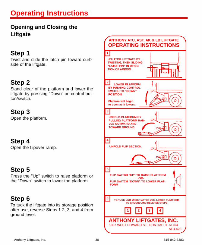
Opening and Closing theLiftgate
Step 1Twist and slide the latch pin toward curb-side of the liftgate.
Step 2Stand clear of the platform and lower theliftgate by pressing "Down" on control but-ton/switch.
Step 3Open the platform.
Step 4Open the flipover ramp.
Step 5Press the "Up" switch to raise platform orthe "Down" switch to lower the platform.
Step 6To tuck the liftgate into its storage positionafter use, reverse Steps 1 2, 3, and 4 fromground level.
Anthony Liftgates, Inc. 30 815-842-3383
UNLATCH LIFTGATE BYTWISTING, THEN SLIDING“LATCH PIN” IN DIREC-TION OF ARROW
ANTHONY ATU, AST, AK & LB LIFTGATEOPERATING INSTRUCTIONS
LOWER PLATFORMBY PUSHING CONTROLSWITCH TO “DOWN”POSITION
Platform will begin to open as it lowers.
UNFOLD PLATFORM BYPULLING PLATFORM HAN-DLE OUTWARD ANDTOWARD GROUND.
UNFOLD FLIP SECTION.
FLIP SWITCH “UP” TO RAISE PLATFORM-OR-
FLIP SWITCH “DOWN” TO LOWER PLAT-FORM
TO TUCK UNIT UNDER AFTER USE, LOWER PLATFORMTO GROUND AND REVERSE STEPS
1 432
6
5
4
3
2
1
ANTHONY LIFTGATES, INC.1037 WEST HOWARD ST., PONTIAC, IL 61764
ATU-423
Operating Instructions
Monthly InspectionSPECIAL NOTE: As of December 1994Anthony Tuckunder Liftgates are “Service-Free”. This means that newer liftgateshave lubrication-free bushings at the majorpivot points which, of course, do notrequire lubrication. Consequently theseliftgates do not have grease zerks. Modelsmanufactured previous to December1994, with grease zerks, require routinelubrication at major pivot points.1. Make sure the liftgate operates freely
and smoothly throughout its entirerange of movement.
2. Check for damage to the liftgate suchas bent or distorted members, or anycracked weld which may have resultedfrom overload or abuse. Check forexcessively worn parts. Replace bush-ings and pins if extremely worn.
3. Check all pins and pivot points. Makesure they are secured with properretainers.
4. Make sure platform is angled upwardfrom truck bed 1/2 to 3/4 inch whenraised to bed height. See PlatformAdjustment for shimming procedure.
5. Make sure all electrical wires, switches,and connections are in good workingcondition and operate properly.
6. Check for oil leaks in these areas:a. Hydraulic lift cylinder.b. Hydraulic hoses. Replace if they
show signs of leakage or excessiveabrasion of the covering.
c. Check all hydraulic fittings fordamage or leaks. Tighten fittingsto stop leaks or replace if dam-aged.
7. Check reservoir oil level.a. Gravity down models - With the
platform on the ground, the oillevel should be within 1/2 inch ofthe top of the reservoir.
b. Power down models - Place lift-gate in the fully raised, the oil levelshould be within 1/2 inch of the topof the reservoir.
c. Fill as required with Mobil DTE-13oil or Penzoil AWX AutomaticTransmission Fluid or equivalent.
IMPORTANT NOTICEUse only Mobil DTE-13 or PenzoilAWX Automatic TransmissionFluid or equivalent in the powerunit reservoir. Do not use brakefluid.
8. Check the fluid level of the vehicle bat-tery. Fill as required.
9. Examine all Warning, Capacity, andOperational Decals. If they are notreadable they should be replaced.Decals may be obtained free of chargefrom Anthony Liftgates, Inc.
10. Oil the roller wheel and make sure itspins freely.
815-842-3383 31 Anthony Liftgates, Inc.
Quick Check Maintenance GuideMaintenance Section
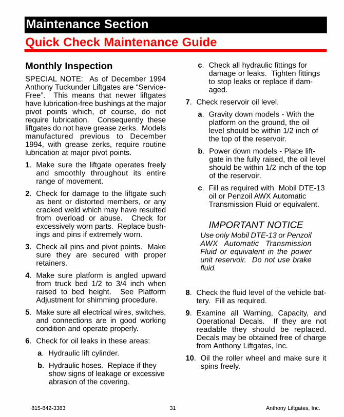
Platform Adjustment (adding shims)The ramp (outboard) end of platform shouldbe 1/2 to 3/4 inches higher than truck floor.If the outboard end of the platform is sag-ging, add shims as described below, toraise the end. Shimming is a normal pro-cedure as the liftgate ages and the partsbecome worn.1. Position the necessary amount of
“shim plates” in the contact areabetween the cam plates and platform.
Add shims to this area to eliminate sagging.
2. Weld the steel shim plates to the blockson platform.
3. When the platform is lowered to theground, it should touch at the lift armend and at the ramp end.
Liftgate should contact the ground at these twolocations.
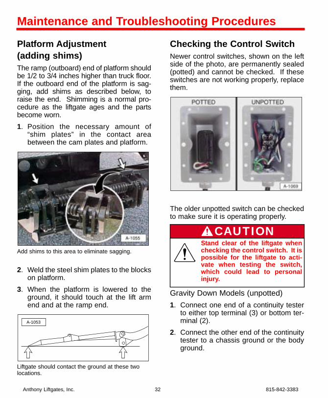
Checking the Control SwitchNewer control switches, shown on the leftside of the photo, are permanently sealed(potted) and cannot be checked. If theseswitches are not working properly, replacethem.
The older unpotted switch can be checkedto make sure it is operating properly.
Gravity Down Models (unpotted)1. Connect one end of a continuity tester
to either top terminal (3) or bottom ter-minal (2).
2. Connect the other end of the continuitytester to a chassis ground or the bodyground.
A-1053
Anthony Liftgates, Inc. 32 815-842-3383
Maintenance and Troubleshooting Procedures
Stand clear of the liftgate whenchecking the control switch. It ispossible for the liftgate to acti-vate when testing the switch,which could lead to personalinjury.
CAUTION
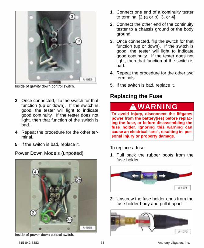
Inside of gravity down control switch.
3. Once connected, flip the switch for thatfunction (up or down). If the switch isgood, the tester will light to indicategood continuity. If the tester does notlight, then that function of the switch isbad.
4. Repeat the procedure for the other ter-minal.
5. If the switch is bad, replace it.
Power Down Models (unpotted)
Inside of power down control switch.
1. Connect one end of a continuity testerto terminal [2 (a or b), 3, or 4].
2. Connect the other end of the continuitytester to a chassis ground or the bodyground.
3. Once connected, flip the switch for thatfunction (up or down). If the switch isgood, the tester will light to indicategood continuity. If the tester does notlight, then that function of the switch isbad.
4. Repeat the procedure for the other twoterminals.
5. If the switch is bad, replace it.
Replacing the Fuse
To replace a fuse:1. Pull back the rubber boots from the
fuse holder.
2. Unscrew the fuse holder ends from thefuse holder body and pull it apart.
815-842-3383 33 Anthony Liftgates, Inc.
To avoid injury, disconnect the liftgatespower from the battery(ies) before replac-ing the fuse, or before disassembling thefuse holder. Ignoring this warning cancause an electrical “arc”, resulting in per-sonal injury or property damage.
WARNING
3. Slide the fuse holder body one direc-tion (left or right) to expose the blownfuse.
4. Loosen the screws from each end ofthe fuse and remove it. Replace thefuse with the same size (Amperage)fuse as the one removed. If you areunsure of the replacement fuse amper-age, contact Anthony for your specificsize fuse. Retighten the screws.
5. Re- assemble the fuse in reverse order.Be sure the rubber boots are sealedaround the fuse holder and cable.
6. Re-connect power after you are certainliftgate area is clear.
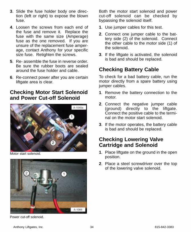
Checking Motor Start Solenoidand Power Cut-off Solenoid
Motor start solenoid.
Power cut-off solenoid.
Both the motor start solenoid and powercut-off solenoid can be checked bybypassing the solenoid itself.1. Use jumper cables for this test.2. Connect one jumper cable to the bat-
tery side (2) of the solenoid. Connectthe other cable to the motor side (1) ofthe solenoid.
3. If the liftgate is activated, the solenoidis bad and should be replaced.
Checking Battery CableTo check for a bad battery cable, run themotor directly from a spare battery usingjumper cables.1. Remove the battery connection to the
motor.2. Connect the negative jumper cable
(ground) directly to the liftgate.Connect the positive cable to the termi-nal on the motor start solenoid.
3. If the motor operates, the battery cableis bad and should be replaced.
Checking Lowering ValveCartridge and Solenoid1. Place liftgate on the ground in the open
position.2. Place a steel screwdriver over the top
of the lowering valve solenoid.
Anthony Liftgates, Inc. 34 815-842-3383
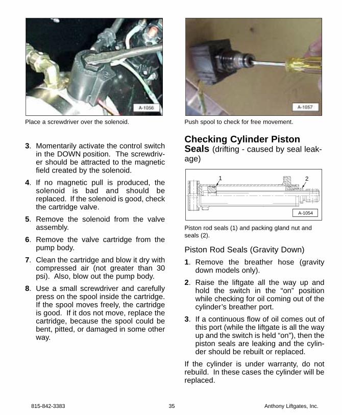
Place a screwdriver over the solenoid.
3. Momentarily activate the control switchin the DOWN position. The screwdriv-er should be attracted to the magneticfield created by the solenoid.
4. If no magnetic pull is produced, thesolenoid is bad and should bereplaced. If the solenoid is good, checkthe cartridge valve.
5. Remove the solenoid from the valveassembly.
6. Remove the valve cartridge from thepump body.
7. Clean the cartridge and blow it dry withcompressed air (not greater than 30psi). Also, blow out the pump body.
8. Use a small screwdriver and carefullypress on the spool inside the cartridge.If the spool moves freely, the cartridgeis good. If it dos not move, replace thecartridge, because the spool could bebent, pitted, or damaged in some otherway.
Push spool to check for free movement.
Checking Cylinder PistonSeals (drifting - caused by seal leak-age)
Piston rod seals (1) and packing gland nut andseals (2).
Piston Rod Seals (Gravity Down)1. Remove the breather hose (gravity
down models only).2. Raise the liftgate all the way up and
hold the switch in the “on” positionwhile checking for oil coming out of thecylinder’s breather port.
3. If a continuous flow of oil comes out ofthis port (while the liftgate is all the wayup and the switch is held “on”), then thepiston seals are leaking and the cylin-der should be rebuilt or replaced.
If the cylinder is under warranty, do notrebuild. In these cases the cylinder will bereplaced.
A-1054
1 2
815-842-3383 35 Anthony Liftgates, Inc.
Piston Rod Seals (Power Down)1. Check the lowering valve. Make sure it
is operating correctly and the valve isnot sticking or dirty.
2. If the lowering valve is operating proper-ly, then the drifting is most likely causedby worn piston seals. Rebuild the cylin-der and replace the piston seals.
If the cylinder is under warranty, do notrebuild. In these cases the cylinder will bereplaced.
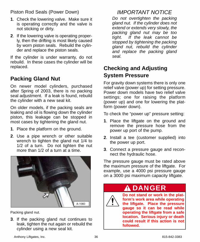
Packing Gland NutOn newer model cylinders, purchasedafter Spring of 2003, there is no packingseal adjustment. If a leak is found, rebuildthe cylinder with a new seal kit.On older models, if the packing seals areleaking and oil is flowing down the cylinderpiston, this leakage can be stopped inmost cases by tightening the gland nut.1. Place the platform on the ground.2. Use a pipe wrench or other suitable
wrench to tighten the gland nut 1/4 to1/2 of a turn. Do not tighten the nutmore than 1/2 of a turn at a time.
Packing gland nut.
3. If the packing gland nut continues toleak, tighten the nut again or rebuild thecylinder using a new seal kit.
IMPORTANT NOTICEDo not overtighten the packinggland nut. If the cylinder does notextend or extends very slowly, thepacking gland nut may be tootight. If the leak cannot bestopped by tightening the packinggland nut, rebuild the cylinderand replace the packing glandseal.
Checking and AdjustingSystem PressureFor gravity down systems there is only onerelief valve (power up) for setting pressure.Power down models have two relief valvesettings; one for raising the platform(power up) and one for lowering the plat-form (power down).To check the “power up” pressure setting:1. Place the liftgate on the ground and
remove the pressure hose from thepower up port of the pump.
2. Install a tee (customer supplied) intothe power up port.
3. Connect a pressure gauge and recon-nect the hydraulic hose.
The pressure gauge must be rated abovethe maximum pressure of the liftgate. Forexample, use a 4000 psi pressure gaugeon a 3000 psi maximum capacity liftgate.
Anthony Liftgates, Inc. 36 815-842-3383
Do not stand or work in the plat-form’s work area while operatingthe liftgate. Place the pressuregauge so it can be read whileoperating the liftgate from a safelocation. Serious injury or deathcould result if this action is notfollowed.
DANGER
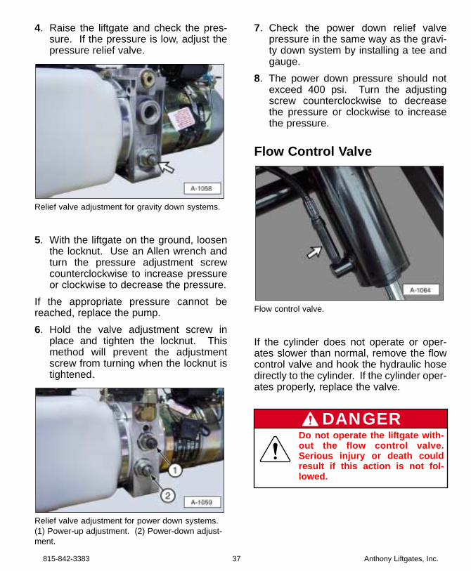
4. Raise the liftgate and check the pres-sure. If the pressure is low, adjust thepressure relief valve.
Relief valve adjustment for gravity down systems.
5. With the liftgate on the ground, loosenthe locknut. Use an Allen wrench andturn the pressure adjustment screwcounterclockwise to increase pressureor clockwise to decrease the pressure.
If the appropriate pressure cannot bereached, replace the pump.6. Hold the valve adjustment screw in
place and tighten the locknut. Thismethod will prevent the adjustmentscrew from turning when the locknut istightened.
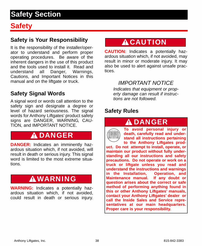
Relief valve adjustment for power down systems.(1) Power-up adjustment. (2) Power-down adjust-ment.
7. Check the power down relief valvepressure in the same way as the gravi-ty down system by installing a tee andgauge.
8. The power down pressure should notexceed 400 psi. Turn the adjustingscrew counterclockwise to decreasethe pressure or clockwise to increasethe pressure.
Flow Control Valve
Flow control valve.
If the cylinder does not operate or oper-ates slower than normal, remove the flowcontrol valve and hook the hydraulic hosedirectly to the cylinder. If the cylinder oper-ates properly, replace the valve.
815-842-3383 37 Anthony Liftgates, Inc.
Do not operate the liftgate with-out the flow control valve.Serious injury or death couldresult if this action is not fol-lowed.
DANGER
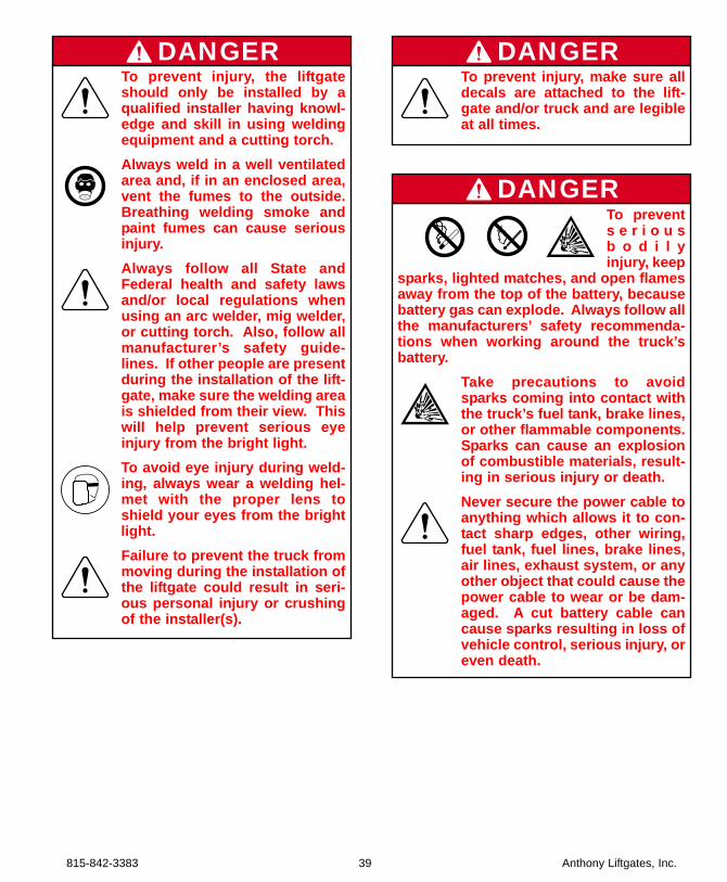
Safety is Your ResponsibilityIt is the responsibility of the installer/oper-ator to understand and perform properoperating procedures. Be aware of theinherent dangers in the use of this productand the tools used to install it. Read andunderstand all Danger, Warnings,Cautions, and Important Notices in thismanual and on the liftgate or truck.
Safety Signal WordsA signal word or words call attention to thesafety sign and designate a degree orlevel of hazard seriousness. The signalwords for Anthony Liftgates’ product safetysigns are DANGER, WARNING, CAU-TION, and IMPORTANT NOTICE.
DANGER: Indicates an imminently haz-ardous situation which, if not avoided, willresult in death or serious injury. This signalword is limited to the most extreme situa-tions.
WARNING: Indicates a potentially haz-ardous situation which, if not avoided,could result in death or serious injury.
CAUTION: Indicates a potentially haz-ardous situation which, if not avoided, mayresult in minor or moderate injury. It mayalso be used to alert against unsafe prac-tices.
IMPORTANT NOTICEIndicates that equipment or prop-erty damage can result if instruc-tions are not followed.
Safety Rules
CAUTION
WARNING
DANGER
Anthony Liftgates, Inc. 38 815-842-3383
To avoid personal injury ordeath, carefully read and under-stand all instructions pertainingto the Anthony Liftgates prod-
uct. Do not attempt to install, operate, ormaintain our product without fully under-standing all our instructions and safetyprecautions. Do not operate or work on atruck or liftgate unless you read andunderstand the instructions and warningsin the Installation, Operation, andMaintenance manual. If any doubt orquestion arises about the correct or safemethod of performing anything found inthis or other Anthony Liftgates’ manuals,contact your Anthony Liftgates’ dealer orcall the Inside Sales and Service repre-sentatives at our main headquarters.Proper care is your responsibility.
DANGER
Safety SectionSafety
815-842-3383 39 Anthony Liftgates, Inc.
To prevent injury, make sure alldecals are attached to the lift-gate and/or truck and are legibleat all times.
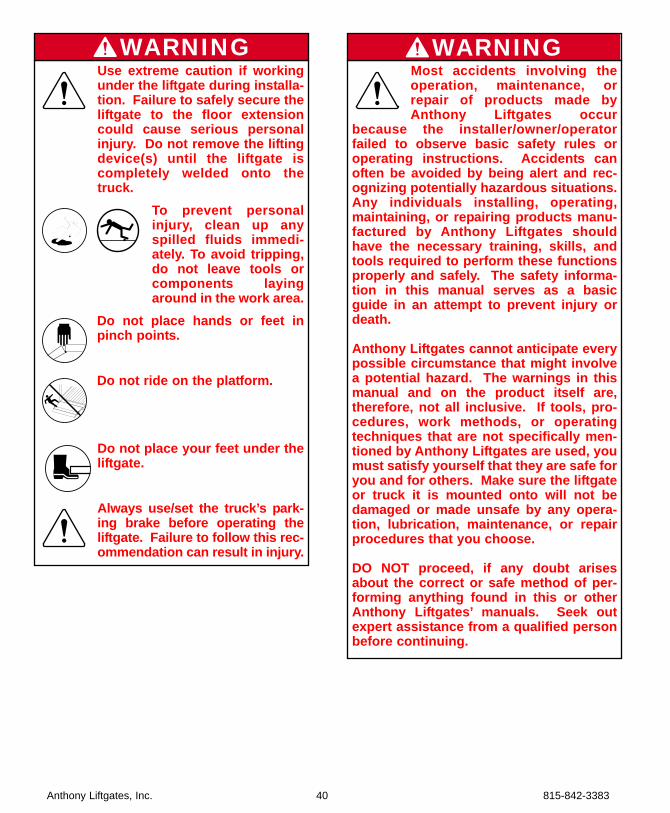
DANGERTo prevent injury, the liftgateshould only be installed by aqualified installer having knowl-edge and skill in using weldingequipment and a cutting torch.Always weld in a well ventilatedarea and, if in an enclosed area,vent the fumes to the outside.Breathing welding smoke andpaint fumes can cause seriousinjury. Always follow all State andFederal health and safety lawsand/or local regulations whenusing an arc welder, mig welder,or cutting torch. Also, follow allmanufacturer’s safety guide-lines. If other people are presentduring the installation of the lift-gate, make sure the welding areais shielded from their view. Thiswill help prevent serious eyeinjury from the bright light.To avoid eye injury during weld-ing, always wear a welding hel-met with the proper lens toshield your eyes from the brightlight.Failure to prevent the truck frommoving during the installation ofthe liftgate could result in seri-ous personal injury or crushingof the installer(s).
DANGER
To prevents e r i o u sb o d i l yinjury, keep
sparks, lighted matches, and open flamesaway from the top of the battery, becausebattery gas can explode. Always follow allthe manufacturers’ safety recommenda-tions when working around the truck’sbattery.
Take precautions to avoidsparks coming into contact withthe truck’s fuel tank, brake lines,or other flammable components.Sparks can cause an explosionof combustible materials, result-ing in serious injury or death. Never secure the power cable toanything which allows it to con-tact sharp edges, other wiring,fuel tank, fuel lines, brake lines,air lines, exhaust system, or anyother object that could cause thepower cable to wear or be dam-aged. A cut battery cable cancause sparks resulting in loss ofvehicle control, serious injury, oreven death.
DANGER
Anthony Liftgates, Inc. 40 815-842-3383
Most accidents involving theoperation, maintenance, orrepair of products made byAnthony Liftgates occur
because the installer/owner/operatorfailed to observe basic safety rules oroperating instructions. Accidents canoften be avoided by being alert and rec-ognizing potentially hazardous situations.Any individuals installing, operating,maintaining, or repairing products manu-factured by Anthony Liftgates shouldhave the necessary training, skills, andtools required to perform these functionsproperly and safely. The safety informa-tion in this manual serves as a basicguide in an attempt to prevent injury ordeath.
Anthony Liftgates cannot anticipate everypossible circumstance that might involvea potential hazard. The warnings in thismanual and on the product itself are,therefore, not all inclusive. If tools, pro-cedures, work methods, or operatingtechniques that are not specifically men-tioned by Anthony Liftgates are used, youmust satisfy yourself that they are safe foryou and for others. Make sure the liftgateor truck it is mounted onto will not bedamaged or made unsafe by any opera-tion, lubrication, maintenance, or repairprocedures that you choose.
DO NOT proceed, if any doubt arisesabout the correct or safe method of per-forming anything found in this or otherAnthony Liftgates’ manuals. Seek outexpert assistance from a qualified personbefore continuing.
WARNINGUse extreme caution if workingunder the liftgate during installa-tion. Failure to safely secure theliftgate to the floor extensioncould cause serious personalinjury. Do not remove the liftingdevice(s) until the liftgate iscompletely welded onto thetruck.
To prevent personalinjury, clean up anyspilled fluids immedi-ately. To avoid tripping,do not leave tools orcomponents layingaround in the work area.
Do not place hands or feet inpinch points.
Do not ride on the platform.
Do not place your feet under theliftgate.
Always use/set the truck’s park-ing brake before operating theliftgate. Failure to follow this rec-ommendation can result in injury.
WARNING
815-842-3383 41 Anthony Liftgates, Inc.
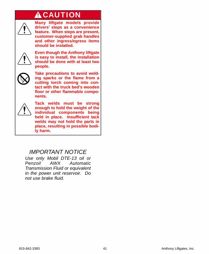
Many liftgate models providedrivers’ steps as a conveniencefeature. When steps are present,customer-supplied grab handlesand other ingress/egress itemsshould be installed.Even though the Anthony liftgateis easy to install, the installationshould be done with at least twopeople.Take precautions to avoid weld-ing sparks or the flame from acutting torch coming into con-tact with the truck bed’s woodenfloor or other flammable compo-nents.Tack welds must be strongenough to hold the weight of theindividual components beingheld in place. Insufficient tackwelds may not hold the parts inplace, resulting in possible bodi-ly harm.
CAUTION
IMPORTANT NOTICEUse only Mobil DTE-13 oil orPenzoil AWX AutomaticTransmission Fluid or equivalentin the power unit reservoir. Donot use brake fluid.
Anthony Liftgates, Inc. 42 815-842-3383
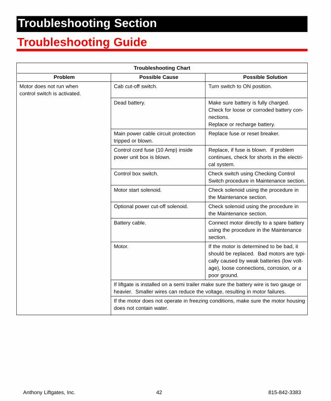
Troubleshooting ChartProblem Possible Cause Possible Solution
Motor does not run when Cab cut-off switch. Turn switch to ON position.control switch is activated.
Dead battery. Make sure battery is fully charged. Check for loose or corroded battery con-nections. Replace or recharge battery.
Main power cable circuit protection Replace fuse or reset breaker.tripped or blown.
Control cord fuse (10 Amp) inside Replace, if fuse is blown. If problem power unit box is blown. continues, check for shorts in the electri-
cal system.
Control box switch. Check switch using Checking ControlSwitch procedure in Maintenance section.
Motor start solenoid. Check solenoid using the procedure inthe Maintenance section.
Optional power cut-off solenoid. Check solenoid using the procedure inthe Maintenance section.
Battery cable. Connect motor directly to a spare batteryusing the procedure in the Maintenancesection.
Motor. If the motor is determined to be bad, itshould be replaced. Bad motors are typi-cally caused by weak batteries (low volt-age), loose connections, corrosion, or apoor ground.
If liftgate is installed on a semi trailer make sure the battery wire is two gauge orheavier. Smaller wires can reduce the voltage, resulting in motor failures.
If the motor does not operate in freezing conditions, make sure the motor housingdoes not contain water.
Troubleshooting SectionTroubleshooting Guide
815-842-3383 43 Anthony Liftgates, Inc.
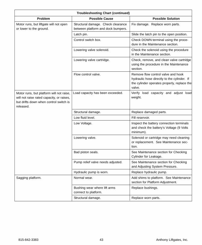
Troubleshooting Chart (continued)Problem Possible Cause Possible Solution
Motor runs, but liftgate will not open Structural damage. Check clearance Fix damage. Replace worn parts.or lower to the ground. between platform and dock bumpers.
Latch pin. Slide the latch pin to the open position.
Control switch box. Check DOWN terminal using the proce-dure in the Maintenance section.
Lowering valve solenoid. Check the solenoid using the procedurein the Maintenance section.
Lowering valve cartridge. Check, remove, and clean valve cartridgeusing the procedure in the Maintenancesection.
Flow control valve. Remove flow control valve and hookhydraulic hose directly to the cylinder. Ifthe cylinder operates properly, replace thevalve.
Motor runs, but platform will not raise,will not raise rated capacity, or raises,but drifts down when control switch is released.
Structural damage. Replace damaged parts.
Low fluid level. Fill reservoir.
Low Voltage. Inspect the battery connection terminalsand check the battery’s Voltage (9 Voltsminimum).
Lowering valve. Solenoid or cartridge may need cleaningor replacement. See Maintenance sec-tion.
Bad piston seals. See Maintenance section for CheckingCylinder for Leakage.
Pump relief valve needs adjusted. See Maintenance section for Checkingand Adjusting System Pressure.
Hydraulic pump is worn. Replace hydraulic pump.
Sagging platform. Normal wear. Add shims to platform. See Maintenance section for Platform Adjustment.
Bushing wear where lift arms Replace bushings.connect to platform.
Structural damage. Replace worn parts.
Load capacity has been exceeded. Verify load capacity and adjust loadweight.
Anthony Liftgates, Inc. 44 815-842-3383
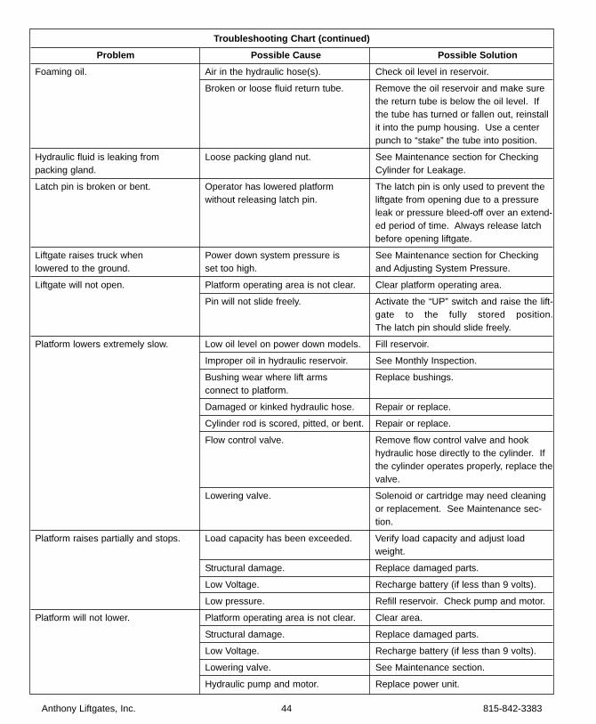
Troubleshooting Chart (continued)Problem Possible Cause Possible Solution
Foaming oil. Air in the hydraulic hose(s). Check oil level in reservoir.
Broken or loose fluid return tube. Remove the oil reservoir and make surethe return tube is below the oil level. Ifthe tube has turned or fallen out, reinstallit into the pump housing. Use a centerpunch to “stake” the tube into position.
Hydraulic fluid is leaking from Loose packing gland nut. See Maintenance section for Checkingpacking gland. Cylinder for Leakage.
Latch pin is broken or bent. Operator has lowered platform The latch pin is only used to prevent the without releasing latch pin. liftgate from opening due to a pressure
leak or pressure bleed-off over an extend-ed period of time. Always release latchbefore opening liftgate.
Liftgate raises truck when Power down system pressure is See Maintenance section for Checkinglowered to the ground. set too high. and Adjusting System Pressure.
Liftgate will not open. Platform operating area is not clear. Clear platform operating area.
Pin will not slide freely. Activate the “UP” switch and raise the lift-gate to the fully stored position.The latch pin should slide freely.
Platform lowers extremely slow. Low oil level on power down models. Fill reservoir.
Improper oil in hydraulic reservoir. See Monthly Inspection.
Bushing wear where lift arms Replace bushings.connect to platform.
Damaged or kinked hydraulic hose. Repair or replace.
Cylinder rod is scored, pitted, or bent. Repair or replace.
Flow control valve. Remove flow control valve and hookhydraulic hose directly to the cylinder. Ifthe cylinder operates properly, replace thevalve.
Lowering valve. Solenoid or cartridge may need cleaningor replacement. See Maintenance sec-tion.
Platform raises partially and stops. Load capacity has been exceeded. Verify load capacity and adjust loadweight.
Structural damage. Replace damaged parts.
Low Voltage. Recharge battery (if less than 9 volts).
Low pressure. Refill reservoir. Check pump and motor.
Platform will not lower. Platform operating area is not clear. Clear area.
Structural damage. Replace damaged parts.
Low Voltage. Recharge battery (if less than 9 volts).
Lowering valve. See Maintenance section.
Hydraulic pump and motor. Replace power unit.

Anthony Liftgates, Inc.1037 W. Howard Street • P.O. Box 615 • Pontiac, IL 61764-0615Ph: 815.842.3383 • Fax: 815.844.3612 • Toll Free: 800.482.0003www.anthonyliftgates.com
Form No. TU-IO-03/03