Embed Size (px)
Citation preview
7/28/2019 Anchoring Safely
http://slidepdf.com/reader/full/anchoring-safely 1/26
The Steamship MutualUnderwriting Association
[B ermudal Limited
7/28/2019 Anchoring Safely
http://slidepdf.com/reader/full/anchoring-safely 2/26
VID EOTEL PRODUC TIONS ANCHORING SAFELY
ANCHORING SAFELY A VIDEOTEL PRODUCTION
In association with
The Steamship Mutual Underwriting Association [Bermuda] Limited
AUTHOR
Johnathan Priest
rnVIDEOTEL productions
84 Newman Street , London wn 3EU
Telephone : +44(0]20 7299 1800Facsimile: +44(0]20 7299 1818
E-mail: mail0videotelmail.com
7/28/2019 Anchoring Safely
http://slidepdf.com/reader/full/anchoring-safely 3/26
VID EOTE l PRODUC TIONS ANCHORING SAFELY
ANCHORING SAFE Y AVIDEOTEL PRODU CTION
In association with
The Steamship Mutual Underwriting Association [Bermudal Limited
THE PRODUCERS WO ULD LIKE TO ACKNOWLEDGE THE ASSISTANCE OF
The Master, Officers and Crew of MV Berge Nord
Bergesen d.y. ASA
International Maritime Organization
The Maersk Company
The Steamship Mutual Underwriting Association [Bermudal Ltd
United Salvage Ltd
Warsash Maritime Centre
World Wide Shipping
CONSULTANTS
Sir William Codrington
Captain Allan MacDowall
PRODUCER
Peter Wilde
WRITER/DIRECTOR
Charles Leigh-Bennett
PRINT AUTHOR
Johnathan Priest
WARNING
Any unauthorised copying, hiring, lending, exhibition diffusion, sale, public performance or othe'r exploitation of this video is strictly prohibited
and may result in prosecution .
© COPYRIGHTVideotel2005
This video is intended to reflect the best available techniques and practices at the time of production, it is intended purely as comment. .
No responsibility is accepted by Videotel, or by any firm, corporation or organisation who or which has been in any way concerned, with the
production or authorised translation, supply or sale of this video for accuracy of any information given hereon or for any omission herefrom
7/28/2019 Anchoring Safely
http://slidepdf.com/reader/full/anchoring-safely 4/26
VI DE OTEL PRO DU CTION S AN CHORING SA FELY
INTRODUCTION 4
What subject does this training cover? 4
How to use this guide? 4
What does this guide provide for trainers? 4
SECTION 1 ANCHORING - THE HAZARDS 5
SECT ION 2 ANCHORING EQUIPMENT 6
2.1 The anchor 6
2.2 The windlass 6
2.3 Preventing damage to the windlass motor and clutch 7
2.4 Preventing damage to the windlass brake 8
SECTION 3 PREPARING TO ANCHOR · 9
3.1 Lying at single anchor 9
3.2 Basic procedure 10
SECTION 4 ANCHORING A VERY LARGE VESSEL 12
4.1 Is equ ipment keeping pace? 12
4.2 The traditional Fore & Aft [in-line] approach 13
SECTION 5 AN ALTERNATIVE APPROACH TO
ANCHORING 16
5.1 The U-turn method 16
5.2 Axial verses rotational forces 16
SECTION 6 USING THE U-TURN METHOD 18
6.1 Operational br iefing 18
6.2 Approach to anchorage 19
SECTION 7 ANCHOR WATCH AND SECURITY 21
SECTION 8 WEIGHING ANCHOR 22
SECTION 9 CONTRIBUTORS 24
3
7/28/2019 Anchoring Safely
http://slidepdf.com/reader/full/anchoring-safely 5/26
VIDEOTEL PR ODUC TIO NS ANCHORING SAFELY
WHAT SUBJECT DOES THIS TRAINING GUIDE COVER?
This training guide examines the general principles of safe anchoring for
medium to large vessels including VLCCs and bulk carriers . The need to
review anchoring procedures is born out of an increased incidence of
personal injuries, damage to anchoring equipment and even loss of shipscaused by the difficulties of anchoring large vessels. An overview is
provided of the proper use of anchoring equipment and its mechanical
tolerances. An alternative to the traditional approach to laying anchor is
also described.
HOW TO USE THIS GUIDE?
The guide is published in an association with a video of the same title
'Anchoring Safely' which provides an overview of anchoring and which
demonstrates some of the techniques described herein. The guide
provides the theoretical background to anchoring procedures
demonstrated in the video and describes them in far greater detail.
To this day, anchoring remains a hotly debated topic and companies and
their masters have strongly hel.d opinions as to how it should be carried
out, many of which are also a matter of company policy. The publishers
wish to make it clear that the information provided in the video and guide
is based on widely accepted best practice but is in no way intended to
provide anything other than guidance.
WHAT DOES THIS GUIDE PROVIDE FOR TRAINERS?
This video and guide provide trainers with a concise overview of the basic
principles of safe anchoring and will help them to increase awareness of
this vitally important aspect of seamanship. The procedures described are
based on a sound understanding of engineering tolerances of anchoring
equipment and the dangers to personnel and equipment associated its
misuse. The main procedures for laying and weighing anchor are
described as well as the requirements for anchor watch . The trainer's
experience and expertise remain essential in interpreting these
procedures in the context of the variety of physical conditions and local
constraints that mariners will encounter.
4
7/28/2019 Anchoring Safely
http://slidepdf.com/reader/full/anchoring-safely 6/26
VIDEOTEL PRODUCTIONS AN CHORING SAFELY
ANCHORING - THE HAZARDS
Anchoring is a highly skilled operation that requires
leadership, teamwork and the utmost vigiLance from thetime the ship arrives at port to the moment the anchor is
weighed. Ships often have to go to anchor unexpectedly
either due to changes in berth availability or weather
conditions. Anchors and windlasses need to be well
maintained and ready for use at any time in port
approaches and harbours.
Pressure on berths around the world means that merchant ships may
have to remain at anchor for long periods . This is demanding on masters,
pilots and crews, especially on the largest vessels where exceptional care
is required to anchor safely and without causing damage to other shipping
or port facilities.
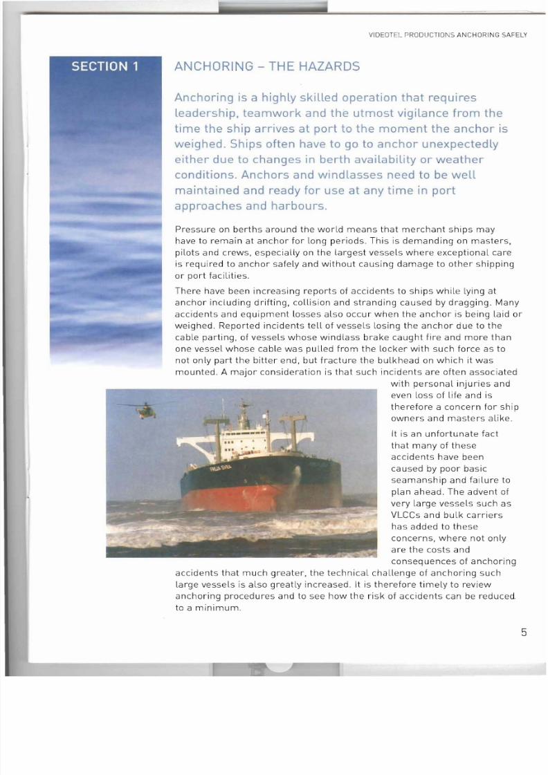
There have been increasing reports of accidents to ships while lying at
anchor including drifting, collision and stranding caused by dragging. Many
accidents and equipment losses also occur when the anchor is being laid or
weighed. Reported incidents tell of vessels losing the anchor due to the
cable parting, of vessels whose windlass brake caught fire and more than
one vessel whose cable was pulled from the locker with such force as tonot only part the bitter end, but fracture the bulkhead on which it was
mounted. A major consideration is that such inc idents are often associated
with personal injuries and
even loss of life and is
therefore a concern for ship
owners and masters alike.
It is an unfortunate fact
that many of these
accidents have been
caused by poor basicseamanship and failure to
plan ahead. The advent of
very large vessels such as
VLCCs and bulk carriers
has added to these
concerns, where not only
are the costs and
consequences of anchoring
accidents that much greater, the technical challenge of anchoring such
large vessels is also greatly increased. It is therefore timely to reviewanchoring procedures and to see how the risk of accidents can be reduced.
to a minimum.
5
7/28/2019 Anchoring Safely
http://slidepdf.com/reader/full/anchoring-safely 7/26
VIDEOTEL PRO DUCTIONS AN CHORIN G SAFELY
ANCHORING
EQUIPMENT
SPECIFICATION
for 150,000 tonne
deadweight ship
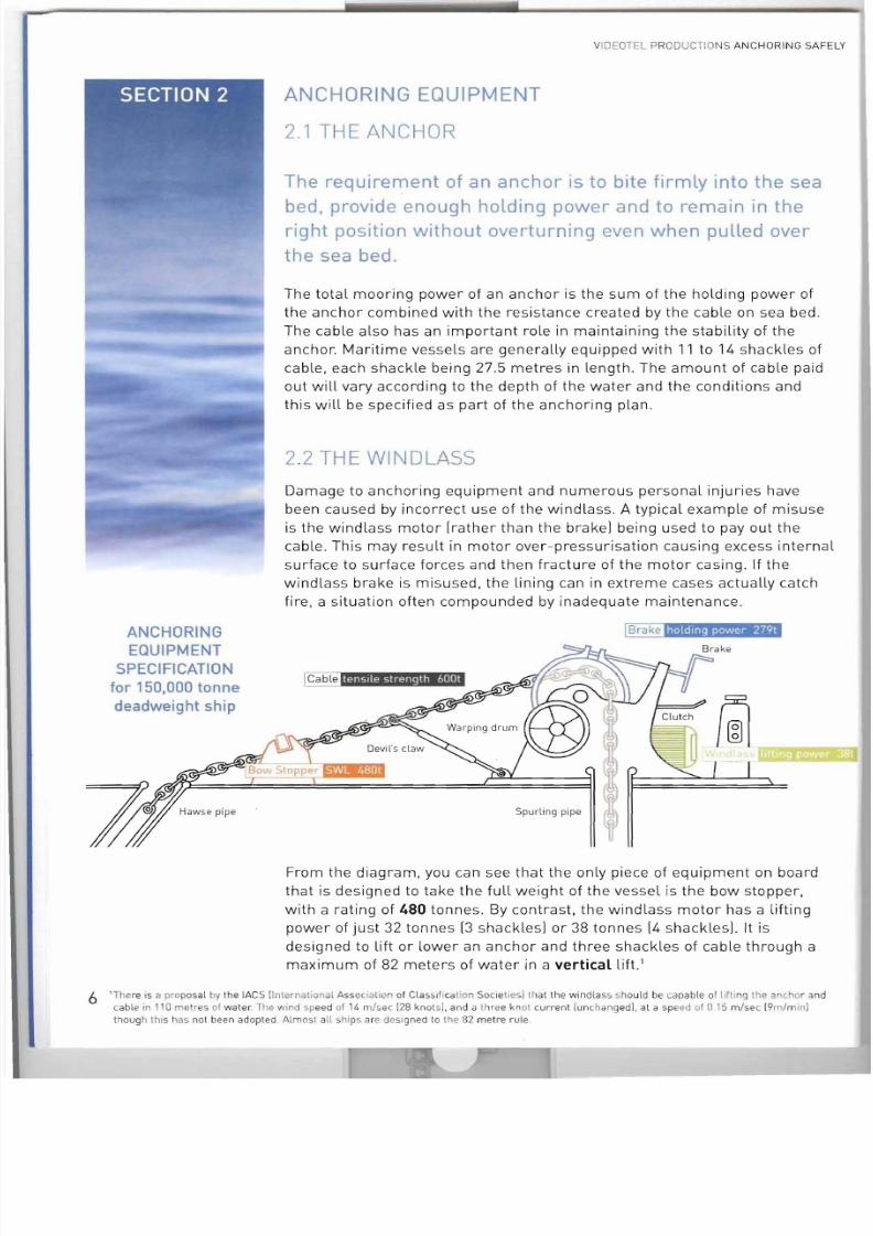
ANCHORING EQUIPMENT
2.1 THE ANCHOR
The requirement of an anchor is to bite firmly into the seabed, provide enough holding power and to remain in the
right position without overturning even when pulled over
the sea bed.
The total mooring power of an anchor is the sum of the holding power of
the anchor combined with the resistance created by the cable on sea bed.
The cable also has an important role in maintaining the stability of the
anchor. Maritime vessels are generally equipped with 11 to 14 shack les of
cable, each shackle being 27 .5 metres in length. The amount of cable paidout will vary according to the depth of the water and the conditions and
this will be specified as part of the anchoring plan.
2.2 THE WINDLASS
Oamage to anchoring equipment and numerous personal injuries have
been caused by incorrect use of the windlass . A typical example of misuse
is the windlass motor [rather than the brake! being used to payout the
cable . This may result in motor over-pressurisation causing excess internal
surface to surface forces and then fracture of the motor casing . If the
windlass brake is misused, the lining can in extreme cases actually catch
fire, a situation often compounded by inadequate maintenance .
ICab le "4"."M"9""'i't',In'
Spur li ng pipe
From the diagram, you can see that the only piece of equipment on board
that is designed to take the full weight of the vessel is the bow stopper,
with a rating of 480 tonnes. By contrast, the windlass motor has a lifting
power of just 32 tonnes [3 shacklesl or 38 tonnes [4 shackles!' It is
designed to l ift or lower an anchor and three shackles of cable through a
maximum of 82 meters of water in a verticallift.l
6 I Th ere IS a proposa l by the lACS (International Asso cIatIon of Cla sslflcalion Soc ietlesl that the wi ndlass should be cap ab le 01 ifting the anchor and
cable in 110 me r s of wa ter The wind speed of 14 m/sec 128 knots l. and a three kn ot cur re nt lunchang ed l. at a speed of 0 I Sm /se c 19m/m in i
thoug h this has not been adopted . Alm osl all ships are deS gned to the 82 metre rule.
7/28/2019 Anchoring Safely
http://slidepdf.com/reader/full/anchoring-safely 8/26
VIDEOT EL PR ODUCTIONS ANCH ORING SAFELY
The crew should have a clear understanding of the implications of any
variation from the vertical [up-down] position of the cable while the anchor
is being manoeuvred. Any angle out of the vertical indicates horizontal
force that includes part of the ship 's mass, which strictly speaking is not
allowed for in the specification. Any changes in the alignment of the cablerelative to the hull should be communicated to the bridge immediately so
that the position of the ship can be altered to remove the load on the
cable.
A 150,000 tonne deadweight ship has the following anchor equipment
rated 'as new' according to the Classification Society rules:
LIFTING POWER OF ANCHOR WINDLASS 38 TONNES FORCE
WINDLASS BRAKE HOLDING POWER 279 TONNES FOR CE
CABLE STOPPER S , ~ F E WORKING LOAD 480 TONNES FORCE
ULTIMATE TENSIL E STRENGTH OF CABLE 600 TONNES FORCE
LENGTH OF 1 CABLE - I SIDE 13 SHACKLES
WEIGHT OF 1 SHACKLE OF CABLE 7.2 TONNES FORC E
WEIGHT OF 1ANCHOR 10.6 TONNES FORCE
Tankers are also fitted with two bow stoppers each rated at 200 tonnes
force for SBMs.
2.3 PREVENTING DAMAGE TO THE WINDLASS MOTOR
AND CLUTCH
Whether electric, hydraulic or steam, the windlass is designed purely to
control the weight of the anchor and three [or fourl shackles of cable. In
particular, the windlass gearbox should not be used as a low ratio box as
in a motor vehicle where the gears are used to slow its descent down hill.
If the gear bo x is subject to such reverse forces, serious mechanical
damage is likely to result.
Exceeding the designed limits of hydraulically powered windlasses willcause the system to become over pressurised. If bearing pressures within
the motor are exceeded, metal will be shaved off its components . These
shavings pass through the coarse filter and into the pump . Further
increase in bearing pressure can cause the casing to crack . In such a
situation, the veered cable cannot be recovered.
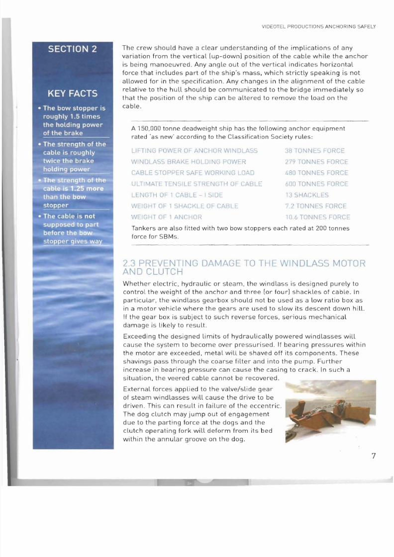
External forces appl ied to the valve/slide gear
of steam windlasses will cause the drive to be
driven. This can result in failure of the eccentric.
The dog clutch may jump out of engagement
due to the parting force at the dogs and theclutch operating fork will deform from its bed
within the annular groove on the dog.
7
7/28/2019 Anchoring Safely
http://slidepdf.com/reader/full/anchoring-safely 9/26
VIDEOTEL PRODU CTIONS ANCHORING SAFELY
Failure to insert the clutch lever securing pin will also lead to clutch
disengagement. If the faces are badly worn, the clutch can jump out of
gear even if the clutch operating lever is properly pinned because the fork
is not sufficiently strong to resist the force pushing the dogs apart. The
fork may also have become distorted.
2.4 PREVEN TING DAMAGE TO THE WINDLASS BRAKE
The windlass brake, not the motor, should be used for paying out the cable.
This is because the brake has a rated static applicable force some 10 times
that sustainable by the motor. However, use of the brake relies heavily on
the skill of the crew and the proper 'as new' maintenance of the brake
mechanism. On larger vessels, the brake should always be manned by two
crew members as the rated force cannot be applied by one man alone.
A NUMBER OF SITUAT IONS WILL LEAD TO BRAKE DAMAGE
• Brake has been screwed up tight but the vessel's momentum
causes it to slip
• Slipping causes heat generation and the brake to fade
• Heat causes the brake band to expand and so become less tight
• Heating by friction causes the brake to fade even more
LIKE THE MOTOR. THE BRA KE HAS VERY SPEC IFIC DES IGN LIMITATIONS:
• The windlass brake is designed to control the cable running out
and to stop it vertically without the ships weight on it
• The windlass brake is not designed to arrest the motion of the ship
• The windlass brake is not designed to hold the mass of the ship
Brake use should ideally be practiced a minimum of once a month fo r each
windlass. Failure to do this will quickly lead to seizure of parts because sea
water causes very rapid rust build-up . Talking through the procedure is
also a helpful way to remind crew of the precise sequence of events. In an
emergency, having the skill and ability to drop the anchor will save the day.
Use of the motor rather than the brake could have insurance implications
due to improper use of equipment.
The bow stopper must be engaged and the motor declutched when the drop
is finished, with the cable in the up and down position . As you can see from
its load specification, the bow stopper has 1.7 times the holding power of
the brake and is the only piece of equipment that is designed to take the
full load of the ship at anchor. However, in order to be effective, the bar of
the bow stopper must lie on the horizontal link with the locking bar in place
with no gap that could allow the tongue to lift, otherwise the bow stopper
could ride over the vertical link when weight comes on the cable and distort
the locking bar.
8
7/28/2019 Anchoring Safely
http://slidepdf.com/reader/full/anchoring-safely 10/26
VID EOTEL PRODUCTIONS AN CHORING SAFELY
PREPARING TO ANCHOR
Advanced planning and excellent communications
between the bridge and the anchoring team are essential
to safe anchoring. The master will ensure that the crew is
trained in the use of the anchoring equipment and has
access to accurate and up-to-date information about the
anchorage so that an anchoring plan can be prepared.
The master should select an anchorage that is sheltered, with good
holding ground and an appropriate depth, depending on the ships own
manoeuvrability and conditions. Weather and sea conditions and dangers
such as submarine cables, pipes and wrecks should al l be taken into
consideration.
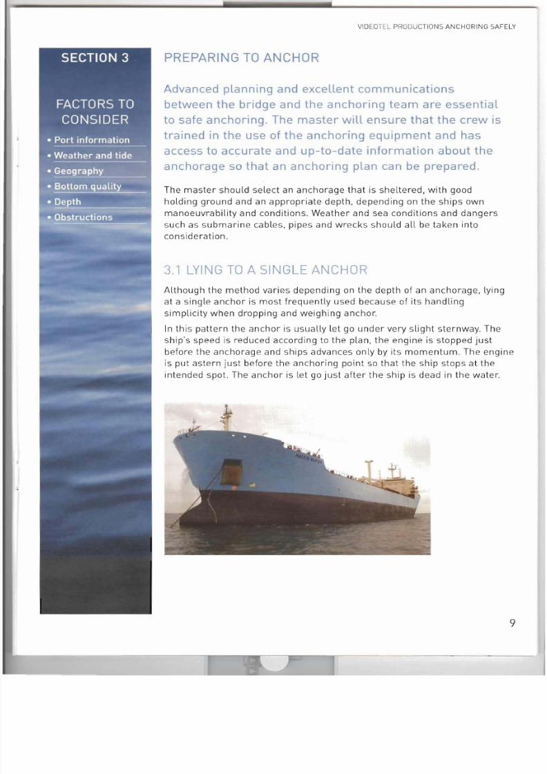
3.1 LYING TO A SINGLE ANCHOR
Although the method varies depending on the depth of an anchorage, lying
at a single anchor is most frequently used because of its handling
simplicity when dropping and weighing anchor.
In this pattern the anchor is usually let go under very slight sternway. The
ship s speed is reduced according to the plan, the engine is stopped just
before the anchorage and ships advances only by its momentum. The engineis put astern just before the anchoring point so that the ship stops at the
intended spot. The anchor is le t go just after the ship is dead in the water.
9
7/28/2019 Anchoring Safely
http://slidepdf.com/reader/full/anchoring-safely 11/26
VIOEOTE L P ODUCTIO 5 ANCHORING SAFELY
3.2 BASIC PROCEDURE
Here is the basic procedure for anchoring a small to medium size vessel:
BEFORE ARRIVAL AND AS PART OF THE ANCHORING PLAN
• Select the position of the anchorage and plan the approach
• Determine how to reduce the ship's speed from the initial approach
to the intended anchorage
• Establish the depth of water, nature of bottom, which anchor to use
and how much cable to payout
• Decide manning for anchoring including the personnel on bridge,
engine room, fo'c'sle, pilot ladder or gangway if required
• Brief the anchoring team
SHORTLY BEFOR E ARRIVAL
• Clear the anchors, hawse and spurling pipes
• Test the windlass and brake
• Test communications
• Prepare to display anchor signal. (ball daytime, lights at night]
ON NEARING THE ANCHfJRAGE , AMEND TH E PI..AN TO INCORPORATE:
• Other ships in the anchorage
• Local weather and sea conditions
• Local navigation warnings and regulations
• Orders from the authorities
• Advice from the pilot or Vessel Traffic Services
APPROACH THE ANCHORING POSITION BY HEADING INTO THE
PREDOMINANT FORCE IEITHER WIND OR CURRENT/TIDAL STREAM,
USUALLY THE LADER)
TAKE WAY OFF THE SHIP AND THEN MAKE VERY SLIGHT STERNWAY
LET GO THE ANCHOR. CONTROLLING WITH THE BRAKE ONCE THE
ANCHOR IS ON THE SEA BED AND SLOWLY PAYING OUT AS THE SHIP
MOVES ASTERN
DISPLAY THE PROPER SIGNAL FOR A VESSEL AT ANCHOR AT NIGHT,
SWITCH OFF THE STEAMING L1GH S
10
7/28/2019 Anchoring Safely
http://slidepdf.com/reader/full/anchoring-safely 12/26
VIDEOTEL PRODUCTIONS ANCHORING SAFELY
KEEP THE BRIDGE INFORMED WHETHER THE CABLE IS TIGHT AND HOW IT
IS LEADING , tOR EXAMPLE "UP AND DOWN" OR '·TIG HT AND LEAD IN G'
TELL THE MASTER HOW MANY DEGREES THERE ARE BETWEEN THE
ANCHOR AND THE BOW , SO THAT HE CAN ASSESS WHETHER THE
ANCHOR IS UNDER ANY STRAIN
WHEN THE CABLE HAS BEEN PAID OUT TO THE AGREED SHACKLE MAR K
['FOUR IN THE WATER ' "SIX ON DECK : OR SIMILAR!, THEN APPLY THE
BRAKE THE BOW STOPPER SHOULD THEN BE APPLIED AND SECURED
WITH THE PIN, THE SHIP SHOULD BE STOPPED OVER THE GROUND US IN G
THE ENGINE
WAIT FOR THE CABLE TO COME TAUT AND THEN SLACKE N TO SHOW THE
SHIP IS ' BROUGHT UP" (WATCH FOR THE CABLE GO IN G TAUT AND THEN
SLACK , TAUT AND THEN SLACK, OR JUDDERING WH ICH MEANS THE
ANCHOR IS DRAGGING)
CHECK THAT THE BRAKE IS SCREWED UP TIGHT AND THE BOW STOPPER
SECURE .
SET ANCHOR WATCH ON THE BRIDGE AND SECURITY WATCHES
DISPLAY ANCHOR LIGHTS / ANCHOR BALL
11
7/28/2019 Anchoring Safely
http://slidepdf.com/reader/full/anchoring-safely 13/26
VID EOTE L PROOU CTIO S ANCHORING SAFELY
SECTION 4
, 1I
, . ~ '
ANCHORING A VERY LARGE VESSEL
4.1 IS EQUIPMENT KEEPING PAC E?
While the general principles described for small tomedium sized vessels also apply to very large vessels
such as VLCCs, the hazards associated both with Laying
anchor and while lying at anchor are greater with a large
vessel, as are the likely consequences of any accidents.
It is a widely held belief that these failures are in part due to the
specifications of anchoring equipment not keeping pace with the
increasing size of vessels . However, an examination of classification
society specifications reveals this not to be the case . In the vast majority ofincidents, accidents are related to a combination of inadequate
preparation fo r anchoring, poor seamanship, lack of communication
between bridge and fo' c'sle, misuse of anchoring equipment and
inappropriate anchoring procedures. Concerns about the increased risks
associated with anchoring very large vessels have led some companies to
issue instructions to the effect that the anchor must be walked out al l the
way, regardless of the depth in which the vessel might be anchoring.
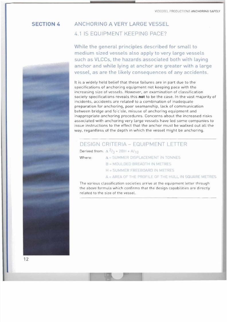
DESIGN CRIT ERIA-
EQUIPMENT LETTER
Derived from: f:... 113 ';' 2BH i AIIO
Where: = SUMMER DISPLACEMENT IN TONNES
B'= MOULDED BREADTH IN METRES
H = SUMMER FREEBOARD IN METRES
,:J., = AREA OF THE PROFILf OF THE HULL IN SQU RE METRES
The various classification societies arrive at the equipment letter through
the above formula which confirms that the design capabilities are directly
related to the size of the vessel,
12
7/28/2019 Anchoring Safely
http://slidepdf.com/reader/full/anchoring-safely 14/26
VIDE OTEL PR ODUC TI O S ANCHORING SAFELY
I
I
SECTION 4
......
.~ ,
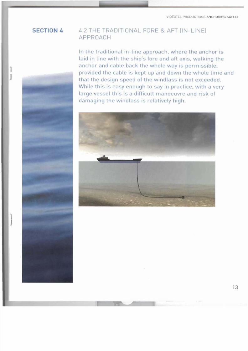
4.2 THE TRADIT IONAL FORE & AFT (IN-LINE]
APPROACH
In the traditional in-line approach, where the anchor islaid in line with the ship's fore and aft axis, walking the
anchor and cable back the whole way is permissible,
provided the cable is kept up and down the whole time and
that the design speed of the windlass is not exceeded.
While this is easy enough to say in practice, with a very
large vessel thiS is a difficult manoeuvre and risk of
damaging the windlass is relatively high .
13
7/28/2019 Anchoring Safely
http://slidepdf.com/reader/full/anchoring-safely 15/26
SECTION 4
VIDEOTEL PRODUCT IO I S ANCHORING SAF ELY
A WORST CASE SCENARIO
A vessel is to anchor in the traditional in-line method. The anchor is
walked back just clear of the water, the engines are put astern and
when the wake has reached the bridge wing the engines are stoppedand the order given to le t go. The cable is allowed to run freely as the
vessel moves slowly astern. At eight shackles on deck the cable is
snubbed and at ten on deck, the brake is screwed up tightly. Inability to
arrest the vessel within the very small distance twixt up and down and
bar taught results in a cable with no elasticity left. Even though the
brake is screwed up tightly, the vessels momentum exceeds the
brake's 279 tonnes resistance and the brake begins to fade. Fading
causes heat generation which, through volumetric expansion, enlarges
the internal diameter of the brake band, thus allowing more fading.
Despite checking the astern motion, the motion of the vessel is too
great and it continues to move astern. The brake band is now so hot it
has expanded such that the cable is now accelerating . Before the
vessel can be brought to a complete stop, the three remaining shackles
have been drawn from the locker. Detachment of the bitter end or
certainly deformation of the chain locker is likely to follow.
The momentum of the cable and its direction of motion are such that
the cable will leave the gypsy and arc above it. When the end finally
parts, energy within the cable is quite sufficient to punch a hole
through 20mm plate and carry away any deck fittings in its path .
Given that putting out 10 shackles with the motor takes in excess of half
an hour at 5cms per second, it is exceedingly difficult, especially with
larger, diesel-powered vessels, to control sternway to such a fine degree.
The long period of time required to payout the anchor cable sometimes
leads to masters using less cable than they should. There have been
incidents where this has lead to anchor dragging and consequent
grounding. Even the most experienced master may run into difficulties andthis is because the traditional approach to anchoring already places him at
a mechanical disadvantage.
Take the example of a vessel anchoring in 50 metres of
water with 10 shackles:
The difference in horizontal distance between the position of the vessel
when the cable is up and down and if, it became bar taut would be
approximately 50 metres. Now, a 150,000 tonne vessel has a beam
approaching 50 metres. So the challenge is easy to visualise; the master istrying to stop a ship of say 300 metres within a distance roughly equal to
its beam.
14
7/28/2019 Anchoring Safely
http://slidepdf.com/reader/full/anchoring-safely 16/26
VID OTEL PRODU CTIO NS ANCH ORIN G SAFELY
SECTION 4
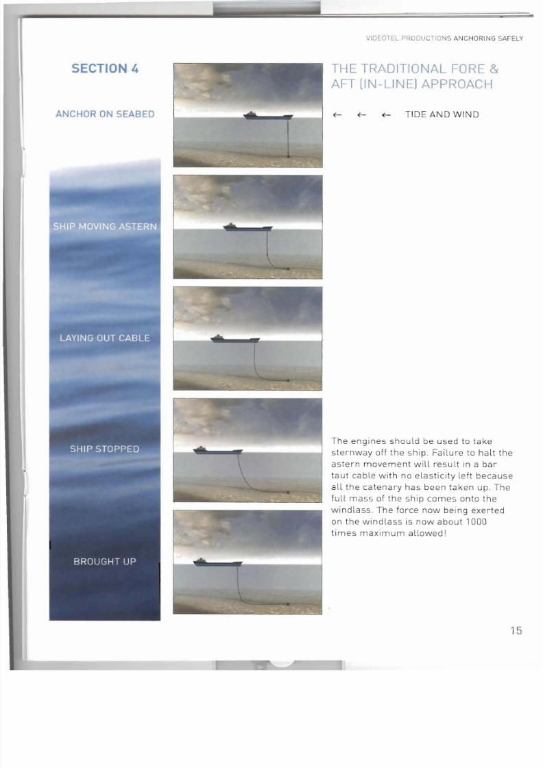
ANCHOR ON SEABED
THE TRADITIONAL FORE &
AFT (IN-LINE) APPROACH
~ ~ ~ TIDE AND WIND
The engines should be used to take
sternway off the ship. Failure to halt the
astern movement will result in a bartaut cable with no elasticity left because
al l the catenary has been taken up. The
full mass of the ship comes onto the
windla ss. The force now being exerted
on the windlass is now about 1000
times maximum allowed l
15
7/28/2019 Anchoring Safely
http://slidepdf.com/reader/full/anchoring-safely 17/26
VIDEOTEL PRODUC -I IONS ANCHORING SAFELY
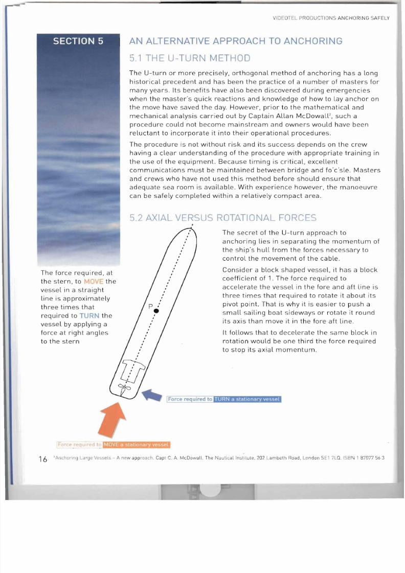
The force required, at
the stern, to ') IE the
vessel in a straight
line is approximately
three times that
required to TURN the
vessel by applying a
force at right angles
to the stern
AN ALTERNATIVE APPROACH TO ANCHORING
5.1 THE U-TU RN METHOD
The U-turn or more precisely, orthogonal method of anchoring has a long
historical precedent and has been the practice of a number of masters for
many years. Its benefits have also been discovered during emergencies
when the master's quick reactions and knowledge of how to lay anchor on
the move have saved the day. However, prior to the mathematical and
mechanical analysis carried out by Captain Allan McDowaW, such a
procedure could not become mainstream and owners would have been
reluctant to incorporate it into their operational procedures .
The procedure is not without risk and its success depends on the crew
having a clear understanding of the procedure with appropriate training in
the use of the equipment. Because timing is critical, excellent
communications must be maintained between bridge and fo·c'sle. Masters
and crews who have not used this method before should ensure that
adequate sea room is available. With experience however, the manoeuvre
can be safely completed within a relatively compact area.
5.2 AXIAL VERSUS ROTATIONAL FORCES
The secret of the U-turn approach to
anchoring lies in separating the momentum of
the ship's hull from the forces necessary to
control the movement of the cable.Consider a block shaped vessel, it has a block
coefficient of 1. The force required to
accelerate the vessel in the fore and aft line is
three times that required to rotate it about its
pivot point . That is why it is easier to push a
small sailing boat sideways or rotate it round
its axis than move it in the fore aft line.
It follows that to decelerate the same block in
rotation would be one third the force required
to stop its axial momentum .
TURN a stationary vessel
Force r"qulre cl 10 I D ! ~ E . 16 ' Anchomg I_arge Vessels - A new ap proach. Ca pt C. A. McDowall. The Naut ical lnsll tute, 202 Lam beth Road, London SEI 7LQ. ISBN 1 87077 56 3
7/28/2019 Anchoring Safely
http://slidepdf.com/reader/full/anchoring-safely 18/26
VIDEOTEL PRODUC TI ONS ANCH ORING SAFELY
This difference is because rotational inertia is less than the axial inertia; it
is a change from straightforward linear acceleration to one of angular
acceleration. A further contributory factor is that in the latter, the distance
from the axis of the centroid is part of the overall equation, whereas in the
former the distance from the axis of the centroid does not enter into the
equation.
However, a ship is not a rectangular block in plan view, but a diamond or
lozenge shape. Taking this as the best fit shape, the block coefficient is not
1 but 0.5. The radius of gyration of the new shape is now one third that of
the full box shape.
Since the radius of gyration is part of the equation which gave a one third
reduction in force required to decelerate the box shape, then it follows that
with a block coefficient of 0.5, the reductions is now one ninth. But the
mass has now been halved, so the factor of 9 must also be halved, giving a
final figure of 4 1/2. Thus for a block coefficient of 0.5 the reduction factoris 4 1/2, whilst for a block coefficient of 1, it is 3. The ship shape lies
somewhere between these two and can be assumed to be equal to 7/2.
Instituting a turn at the point where the anchor is
let go will change the force on the cable from one
of axial translation to one of rotational translation.
But one of the factors of rotational inertia is the
distance from the axis through the centroid. By
using the anchor and cable this distance has now
been increased by the length of the cable, a factor
of 6.5. By applying the two factors [7/2 X 13/2J onefinds the force on the cable is approximately 23
times less than the original case l
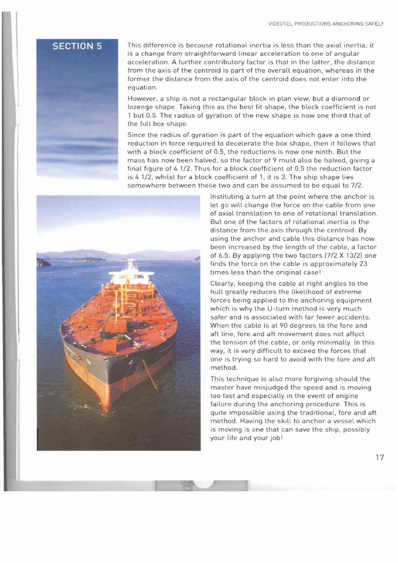
Clearly, keeping the cable at right angles to the
hull greatly reduces the likelihood of extreme
forces being applied to the anchoring equipment
which is why the U-turn method is very much
safer and is associated with far fewer accidents.
When the cable is at 90 degrees to the fore and
aft line, fore and aft movement does not affect
the tension of the cable, or only minimally. In this
way, it is very difficult to exceed the forces that
one is trying so hard to avoid with the fore and aft
method.
This technique is also more forgiving should the
master have misjudged the speed and is moving
too fast and especially in the event of engine
failure during the anchoring procedure. This is
quite impossible using the traditional, fore and aft
method. Having the skill to anchor a vessel which
is moving is one that can save the ship, possibly
your life and your job!
17
7/28/2019 Anchoring Safely
http://slidepdf.com/reader/full/anchoring-safely 19/26
VIDEOTEL PRODUCTIONS ANCHORING SAFELY
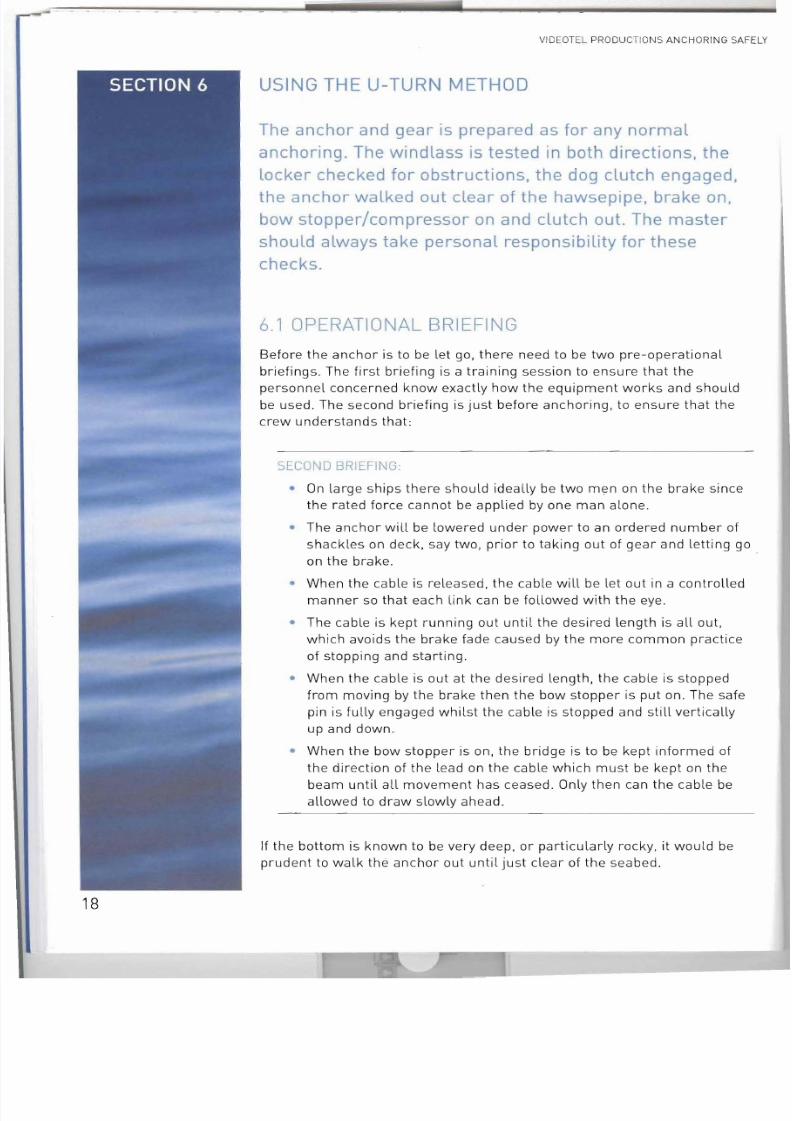
USING THE U-TURN METHOD
The anchor and gear is prepared as for any normaL
anchoring. The windLass is tested in both directions, the
Locker checked for obstructions, the dog clutch engaged,
the anchor walked out clear of the hawsepipe, brake on,
bow stopper/compressor on and clutch out. The master
shouLd always take personal responsibility for these
checks.
6.1 OPERATIONAL BRIEFING
Before the anchor is to be let go, there need to be two pre-operational
briefings. The first briefing is a training session to ensure that the
personnel concerned know exactly how the equipment works and should
be used. The second briefing is just before anchoring, to ensure that the
crew understands that :
SECOND BRIEFING :
• On large ships there should ideally be two men on the brake since
the rated force cannot be applied by one man alone.• The anchor will be lowered under power to an ordered number of
shackles on deck, say two, prior to taking out of gear and letting go .
on the brake.
• When the cable is released, the cable will be let out in a controlled
manner so that each !.ink can be followed with the eye.
• The cable is kept running out until the desired length is all out,
which avoids the brake fade caused by the more common practice
of stopping and starting.
• When the cable is out at the desired length, the cable is stoppedfrom moving by the brake then the bow stopper is put on. The safe
pin is fully engaged whilst the cable is stopped and still vertically
up and down .
• When the bow stopper is on, the bridge is to be kept informed of
the direction of the lead on the cable which must be kept on the
beam until all movement has ceased . Only then can the cable be
allowed to draw slowly ahead .
If the bottom is known to be very deep, or particularly rocky, it would beprudent to walk the anchor out until just clear of the seabed.
18
7/28/2019 Anchoring Safely
http://slidepdf.com/reader/full/anchoring-safely 20/26
VIDEOTEL PRODUCTIONS ANCHORING SAFELY
TIDE AND WINDApproach downwind/tide with
J, minimum steerage way of 2-3 knots. UJ, Hard a·starboard.
Dead slow ahead.
J,
Allow full scope to pay
out in one controlled
movement. Appty bra ke
and compressor
Short bursts of ahead
or as te rn power to keep
the lead as near
perpendicular to the
for ecastle as ispossible .
Short bursts of power
to co ntrol drift. Vessel
bought up . Cable in
s hallow bight on
seabed.
Only sideways drift (ftoP engines
Let go starboard anchor Observe sWing135 0 off course, all forward
\\ - ~ o ' ' ' ' ' ' 5<., '"9'""a." co"'''
\\)v V (
Tension in the cable now
snubbing the bow and the vesselis drifting astern under wind/tide.
r Sl .w."" ,
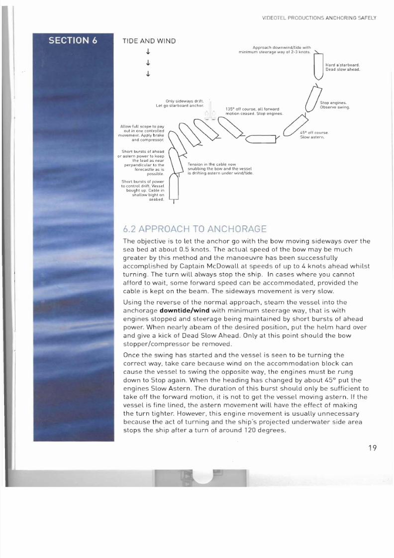
6.2 APPROACH TO ANCHORAGE
The objective is to let the anchor go with the bow moving sideways over the
sea bed at about 0.5 knots . The actual speed of the bow may be much
greater by this method and the manoeuvre has been successfully
accomplished by Captain McDowall at speeds of up to 4 knots ahead whilst
turning. The turn will always stop the ship. In cases where you cannot
afford to wait, some forward speed can be accommodated, provided the
cable is kept on the beam. The sideways movement is very slow.
Using the reverse of the normal approach, steam the vessel into the
anchorage downtide/wind with minimum steerage way, that is with
engines stopped and steerage being maintained by short bursts of ahead
power. When nearly abeam of the desired position, put the helm hard over
and give a kick of Dead Slow Ahead. Only at this point should the bowstopper/compressor be removed.
Once the swing has started and the vessel is seen to be turning the
correct way, take care because wind on the accommodation block can
cause the vessel to swing the opposite way, the engines must be rung
down to Stop again. When the heading has changed by about 45° put the
engines Slow Astern. The duration of this burst should only be sufficient to
take off the forward motion, it is not to get the vessel moving astern. If the
vessel is fine lined, the astern movement will have the effect of making
the turn tighter. However, this engine movement is usually unnecessary
because the act of turning and the ship's projected underwater side areastops the ship after a turn of around 120 degrees.
19
7/28/2019 Anchoring Safely
http://slidepdf.com/reader/full/anchoring-safely 21/26
VIDEOTEL PRODUCT IONS ANCHORING SAFELY
By the time the vessel's heading has changed by 90° the greater
component of its motion will be sideways with only a very small proportion
being in the forward direction. At 135°, all forward motion should have
ceased and the vessel will only be experiencing a small sideways drift. A
short kick Slow Astern may be required to ensure this. The anchor is le t
go in one controlled operation, allowing the full scope to be payed out inone movement. The brake and compressor are applied along with safety
locking pins.
The vessel will continue its sideways drift and draw the cable along the
seabed at right angles to the fo'c'sle. Communication between bridge and
fo'c'sle are paramount to the success of this manoeuvre as the fo'c'sle
officer must keep the bridge informed of the direction of lead . Short kicks
of ahead or astern are given as required in order to keep the lead at right
angles to the vessel.
Eventually the tension in the cable will snub the bow and start to turn the
vessel towards her cable; at this point it may be necessary to use engine
movements to control the rate of turn. As the vessel points on her cable
the effect of the wind/tide will initiate astern motion, again it may be
necessary to check the effect of this by use of engines.
By the time the vessel is laying head to tide/wind the cable will have been
drawn out in an arc on the sea bed and will be acting as an additional
shock absorber.
Once you are accomplished in this manoeuvre, the speed of approach may
be increased just so long as the corresponding astern movement at the
commencement of the turn is also increased. This will not only have theeffect of reducing the forward motion more quickly but wil l also reduce the
radius of the turn.
TRIED AND TESTED
This manoeuvre has been tried and tested on a number of different types
and sizes of vessel. It takes approximately 12-15 minutes from initiation of
turn to bow stopper on . On one occasion it was performed in an
emergency due to main engine failure when the vessel was preceding
.downtide at a speed of 12 knots. One company which had previously been
plagued by accidents, incidents and dangerous occurrences has been
using this method for some five years and since then has not had any
further incidents of failure of anchor gear or other unsafe occurrences
whilst anchoring. However, it is for individual operators and their masters
to assess the most appropriate method of anchoring for their vessels and
this technique is described here purely as an alternative approach which
may have benefits in certain circumstances.
20
7/28/2019 Anchoring Safely
http://slidepdf.com/reader/full/anchoring-safely 22/26
VIDEOTEL PRODUCTIONS AN CHORING SAFE LY
ANCHOR WATCH AND SECURITY
The main purpose of anchor watch is to keep the vessel
safe at all times. In particular, it will be necessary to look
out for signs of anchor dragging such as a swinging
motion of the ship, the ship moving sideways, weather
side constant, cable vibrating. cable constantly taut and
positional changes relative to nearby ships.
The ship 's position should be monitored by whatever means possible and
the master informed if the ship moves outside the scope of the cable. If
anchoring in silt, it may be necessary to weigh and let go anchor every day
or so. It is also important to keep a lookout for any craft approaching orpeople seeking to come on board to ensure that they are legitimate
visitors, following the procedures set out by the company in accordance
with the International Ship and Port Facility Security Code [ISPS Codel.
WATCH KEEPING DUTI ES :
• Monitor ships position
• Maintain continuous effective lookout
• Ensure suitable fire/piracy controls
• Monitor effective communication internally and externally
• Check anchor and cable are ranged correctly
• Ensure correct signals are displayed at correct times
• Note tide and flow changes
• Ensure vessel complies with COLREGs [Regulations fo r Prevention
of Collisions at Sea , Rule 30 Anchored vessels and vessels
aground]
• Inform Master of any changes affecting vessel
21
7/28/2019 Anchoring Safely
http://slidepdf.com/reader/full/anchoring-safely 23/26
VIDEOTE L PR ODUCTIO NS AN CHORING SAFELY
WEIGHING ANCHOR
Weighing anchor requires similar preparations to
anchoring, in particular making sure that all theequipment is functioning properly and that the working
space around it is clear and safe.
Power supplies to the windLass must be switched on and checked and the
proper functioning of the clutch and brake tested, whiLe the cabLe is held
on the bow stopper. The chain locker, spurling pipe and hawse pipes
shouLd be checked . Communications with the bridge should also be
tested.
It must be remembered that the windLass is designed for a vertical lift of
one anchor plus three shackles (or 82 metres] of cabLe. If the anchor is
leading out of the verticaL, this may cause damage if forces in excess of
these limits are applied. The ship's engines and heLm can be used to
bring the cable as near vertical as possible.
When instructed to do so, the windlass should be put into gear, the bow
stopper released with the stopper removed before the brake is released.
No weight must be on the stopper when the locking bars/pins are removed
or a serious accident could ensue. Again when instructed to do so, start to
heave away, making sure the cable is clear and not fouling the ship's
structure, hosing off the mud and debris as the cable comes in .
Normally, the cable washers in the hawse pipe will clear any mud from
the anchor. If the cable is heaviLy coated with clay, then heaving more
slowly usually does the trick. Failing that, a powerful hose should be used .
If the anchor has picked up a cable or other obstruction the windlass
should be stopped immediately and the bridge informed .
If everything is normal, reports should be made to the bridge of how the
cable is leading, when it is clear of the sea bed, [this may not be obvious if
the cable is already vertical! and when it is clear of the water.
The anchor ball should be lowered or anchor Lights switched off when theanchor is weighed.
22
7/28/2019 Anchoring Safely
http://slidepdf.com/reader/full/anchoring-safely 24/26
------ -
- - -
VID EOT EL PRODUCTI ONS ANCHORING SAFELY
SECURING FOR SEA
When the anchor is clean and ready to be stowed, it should be heaved
home into the hawse pipe, the brake applied and bow stopper put on,
together with extra lashings as required. A tight lashing should ensure
that extra weight does not come on the bow stopper. If the anchor isneeded for use in an emergency, the bow stopper can be removed by
hand.
DURING THE VOYAGE
It should be remembered that anchor may s hift and become loose,
especially in heavy seas. The securing may need to be checked and
repeated during the voyage. A loose anchor moving in the hawse pipe can
cause serious damage
23
7/28/2019 Anchoring Safely
http://slidepdf.com/reader/full/anchoring-safely 25/26
VIDEOTEL PRODUCTIONS ANCHORING SAFE
CONTRIBUTORS
The work of Captain Allan McDowall MSc CEng MIMechE MRINA FNI.
Drawings on pages 6, 16, & 19 adapted from originals by J N Wilde.
24

7/28/2019 Anchoring Safely
http://slidepdf.com/reader/full/anchoring-safely 26/26