Embed Size (px)
Citation preview

Anbar University Engineering Mechanics
Engineering college Dynamics
Mechanical Engineering Department Rashaq Abdullah Mohammed
1
Dynamics
Dynamics includes:-
1- Kinematics: study of the geometry of motion.
Relates displacement, velocity, acceleration, and time without reference to
the cause of motion.
Kinetics: study of the relations existing between the forces acting on a
body, the mass of the body, and the motion of the body. Kinetics is used to
predict the motion caused by given forces or to determine the forces
required to produce a given motion.
Kinematics of Particles Mechanics is a branch of the physical sciences that is concerned with the
state of rest or motion of bodies subjected to the action of forces.
Engineering mechanics is divided into two areas of study, namely, statics
and dynamics. Statics is concerned with the equilibrium of a body that is
either at rest or moves with constant velocity. Here we will consider
dynamics, which deals with the accelerated motion of a body. The subject
of dynamics will be presented in two parts: kinematics, which treats only

Anbar University Engineering Mechanics
Engineering college Dynamics
Mechanical Engineering Department Rashaq Abdullah Mohammed
2
the geometric aspects of the motion, and kinetics, which is the analysis of
the forces causing the motion. To develop these principles, the dynamics of
a particle will be discussed first, followed by topics in rigid-body dynamics
in two and then three dimensions.
Position. The straight-line path of a particle will be defined using a
single coordinate axis s, Fig. 1a. The origin 0 on the path is a fixed
point, and from this point the position coordinate s is used to specify
the location of the particle at any given instant. The magnitude of s is
the distance from 0 to the particle, usually measured in meters (m) or
feet (ft), and the sense of direction is defined by the algebraic sign on
s. Although the choice is arbitrary, in this case s is positive since the
coordinate axis is positive to the
right of the origin. Likewise, it is
negative if the particle is located
to the left of O. Realize that
position is a vector quantity since it has both magnitude and direction.
Here, however, it is being represented by the algebraic scalar s since
the direction always remains along the coordinate axi.
Displacement. The displacement of the particle is defined as the
change in its position. For example, if the particle moves from one
point to another, Fig. b, the displacement is

Anbar University Engineering Mechanics
Engineering college Dynamics
Mechanical Engineering Department Rashaq Abdullah Mohammed
3
In this case Δs is
positive since the particle's final
position is to the right of its initial
position, i.e., S’ > s. Likewise, if
the final position were to the left of
its initial position Δs would be
negative
Velocity. If the particle moves through a displacement Δs during the
time interval Δt, the average velocity of the particle during this time
interval is
If we take smaller and smaller values of Δt, the magnitude of Δs becomes
smaller and smaller. Consequently, the instantaneous velocity is a vector
defined as
Since Δt or dt is always positive, the sign used to define the sense of the
velocity is the same as that of Δs or ds.
For example, if the particle is moving to
the right, Fig. c, the velocity is positive;
whereas if it is moving to the left, the
velocity is negative

Anbar University Engineering Mechanics
Engineering college Dynamics
Mechanical Engineering Department Rashaq Abdullah Mohammed
4
Acceleration. Provided the velocity of the particle is known at two
points, the average acceleration of the particle during the time interval Δt
is defined as
Here ΔV represents the difference in the velocity during the time
interval Δt, i.e, Δv = v' - v, Fig. e.

Anbar University Engineering Mechanics
Engineering college Dynamics
Mechanical Engineering Department Rashaq Abdullah Mohammed
5
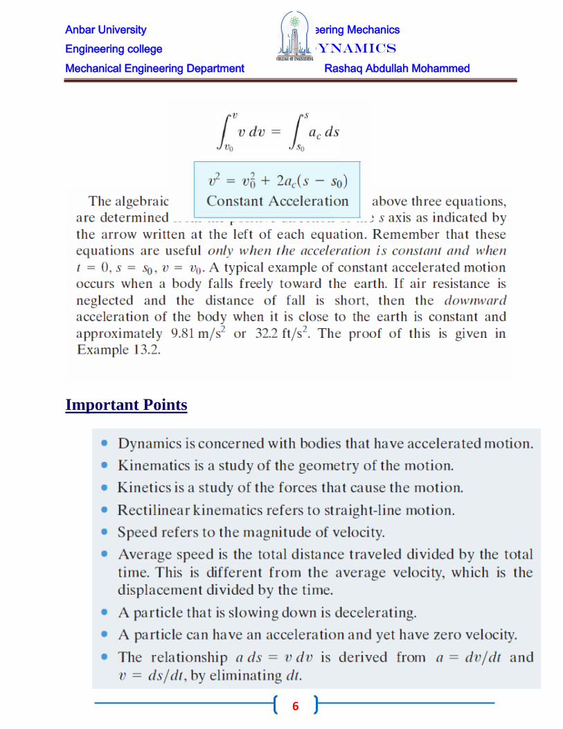
Velocity as a Function of Position
Anbar University Engineering Mechanics
Engineering college Dynamics
Mechanical Engineering Department Rashaq Abdullah Mohammed
6
Important Points

Anbar University Engineering Mechanics
Engineering college Dynamics
Mechanical Engineering Department Rashaq Abdullah Mohammed
7
EXA M P L E -1-
The car in Fig. below moves in a straight line such that for a short time
its velocity is defined by v = (3t + 2t) ft/s , where t is in seconds.
Determine its position and acceleration when t = 3 s. When t = 0, s = 0.

Anbar University Engineering Mechanics
Engineering college Dynamics
Mechanical Engineering Department Rashaq Abdullah Mohammed
8
EXA M P L E -2- A small projectile is fired vertically downward into a
fluid medium with an initial velocity of 60 m/s. Due to the drag resistance
of the fluid the projectile experiences a deceleration of a = (-0.4v3) m/s2,
where v is in m/s. Determine the projectile's velocity and position 4 s after it
is fired.
SOLUT I O N
Coordinate System. Since the motion is
downward, the position coordinate is positive
downward, with origin located at 0, Fig

Anbar University Engineering Mechanics
Engineering college Dynamics
Mechanical Engineering Department Rashaq Abdullah Mohammed
9
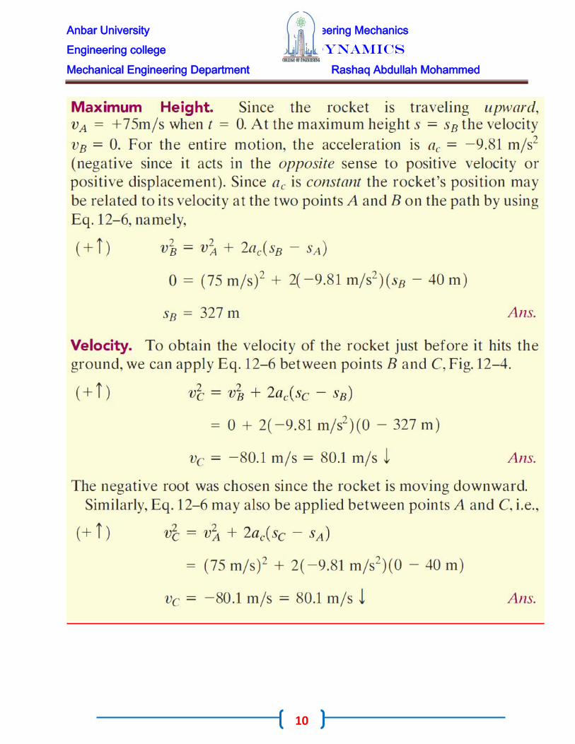
EXA M P L E -3-
During a test a rocket travels upward at 75 m/s, and when it is 40 m from
the ground its engine fails. Determine the maximum
height SB reached by the rocket and its speed just before
it hits the ground. While in motion the rocket is
subjected to a constant downward acceleration of 9.81
m/s2 due to gravity. Neglect the effect of air resistance.
SO LUTI O N:-
Coordinate System. The origin 0 for the position
coordinate s is taken at ground level with positive
upward, Fig
Anbar University Engineering Mechanics
Engineering college Dynamics
Mechanical Engineering Department Rashaq Abdullah Mohammed
10

Anbar University Engineering Mechanics
Engineering college Dynamics
Mechanical Engineering Department Rashaq Abdullah Mohammed
11
PROPLEMS:-
Q1/ Initially, the car travels along a straight road with a speed of 35 m/s. If the brakes
are applied and the speed of the car is reduced to 10 m/s in 15 s, determine the constant
deceleration of the car?
Q2/ A train starts from rest at a station and travels with a constant acceleration of
1 m/s2. Determine the velocity of the train when (= 30 s and the distance traveled
during this time?
Q3/ Car A starts from rest at t = 0 and travels along a straight road with a constant
acceleration of 6 ft/S2 until it reaches a speed of 80 ft/s. Afterwards it maintains this
speed. Also, when t = 0, car B located 6000 ft down the road is traveling towards A at
a constant speed of 60 ft/s. Determine the distance traveled by car A when they pass
each other.
Q4/ A particle travels along a straight line with a velocity v = (12 – 3t2) m/s, where t
is in seconds. When t = 1 s, the particle is located 10 m to the left of the origin.
Determine the acceleration when t = 4 s, the displacement from t = 0 to t = 10 s, and
the distance the particle travels during this time period?

Anbar University Engineering Mechanics
Engineering college Dynamics
Mechanical Engineering Department Rashaq Abdullah Mohammed
12
Q5/ The acceleration of a particle traveling along a straight line is a = k/v, where k is a
constant. If S = 0, v = Vo when t= 0, determine the velocity of the particle as a function
of time t.
Q6/ Tests reveal that a normal driver takes about 0.75 s before he or she can react to a
situation to avoid a collision. It takes about 3 s for a driver having 0.1 % alcohol in his
system to do the same. If such drivers are traveling on a straight road at 30 mph (44
ft/s) and their cars can decelerate at 2 ft/S2, determine the shortest stopping distance d
for each from the moment they see the pedestrians. Moral: If you must drink, please
don't drive ?
Rectilinear Kinematics: Erratic Motion

Anbar University Engineering Mechanics
Engineering college Dynamics
Mechanical Engineering Department Rashaq Abdullah Mohammed
13
When a particle has erratic or changing motion then its position, velocity, and
acceleration cannot be described by a single continuous mathematical function along
the entire path. Instead, a series of functions will be required to specify the motion at
different intervals. For this reason, it is convenient to represent the motion as a graph.
If a graph of the motion that relates any two of the variables s, v, a, t can be drawn,
then this graph can be used to construct subsequent graphs relating two other variables
Since d the variables are related by the differential relationships v = ds/d t, or
a ds = v dv. Several situations occur frequently.
The s-t, v-t, and a-t Graphs. To construct the v-t
graph given the s-t graph, Fig. , the equation v =
ds/dt should be used, since it relates the variables s
and t to v. This equation states that

Anbar University Engineering Mechanics
Engineering college Dynamics
Mechanical Engineering Department Rashaq Abdullah Mohammed
14
For example, by measuring the slope on the s-t
graph when t = t1, the velocity is υ1 , which is
plotted in Fig.. The v-t graph can be
constructed by plotting this and other values at
each instant. The a-t graph can be constructed
from the v-t graph in a similar manner, Fig.,
since
Anbar University Engineering Mechanics
Engineering college Dynamics
Mechanical Engineering Department Rashaq Abdullah Mohammed
15
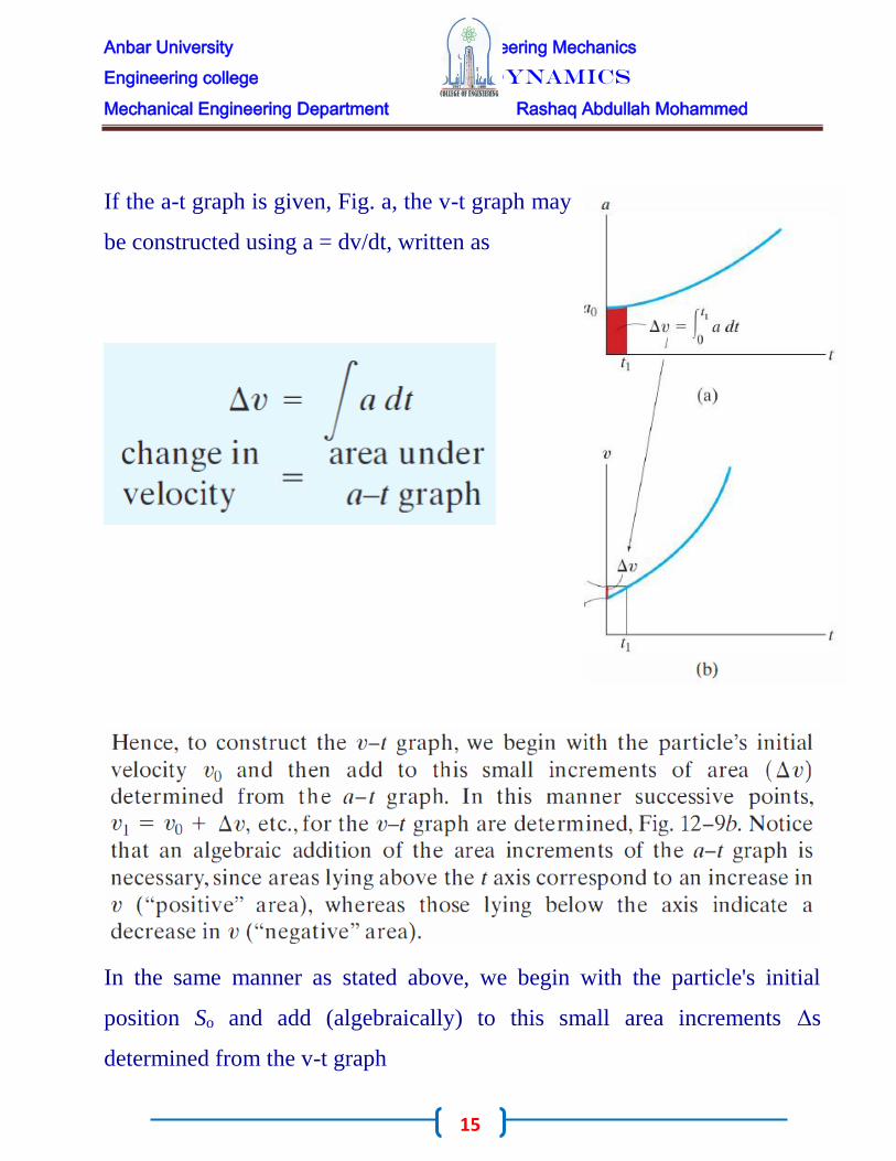
If the a-t graph is given, Fig. a, the v-t graph may
be constructed using a = dv/dt, written as
In the same manner as stated above, we begin with the particle's initial
position So and add (algebraically) to this small area increments Δs
determined from the v-t graph
Anbar University Engineering Mechanics
Engineering college Dynamics
Mechanical Engineering Department Rashaq Abdullah Mohammed
16
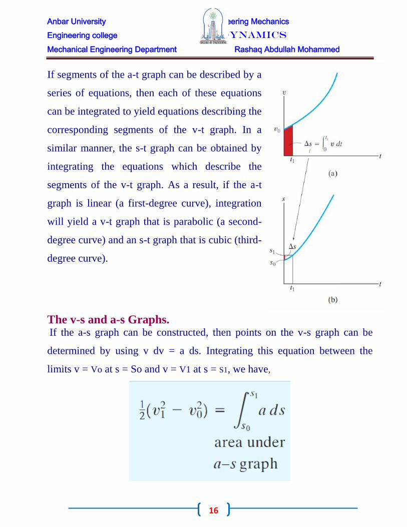
If segments of the a-t graph can be described by a
series of equations, then each of these equations
can be integrated to yield equations describing the
corresponding segments of the v-t graph. In a
similar manner, the s-t graph can be obtained by
integrating the equations which describe the
segments of the v-t graph. As a result, if the a-t
graph is linear (a first-degree curve), integration
will yield a v-t graph that is parabolic (a second-
degree curve) and an s-t graph that is cubic (third-
degree curve).
The v-s and a-s Graphs. If the a-s graph can be constructed, then points on the v-s graph can be
determined by using v dv = a ds. Integrating this equation between the
limits v = Vo at s = So and v = V1 at s = S1, we have,
Anbar University Engineering Mechanics
Engineering college Dynamics
Mechanical Engineering Department Rashaq Abdullah Mohammed
17
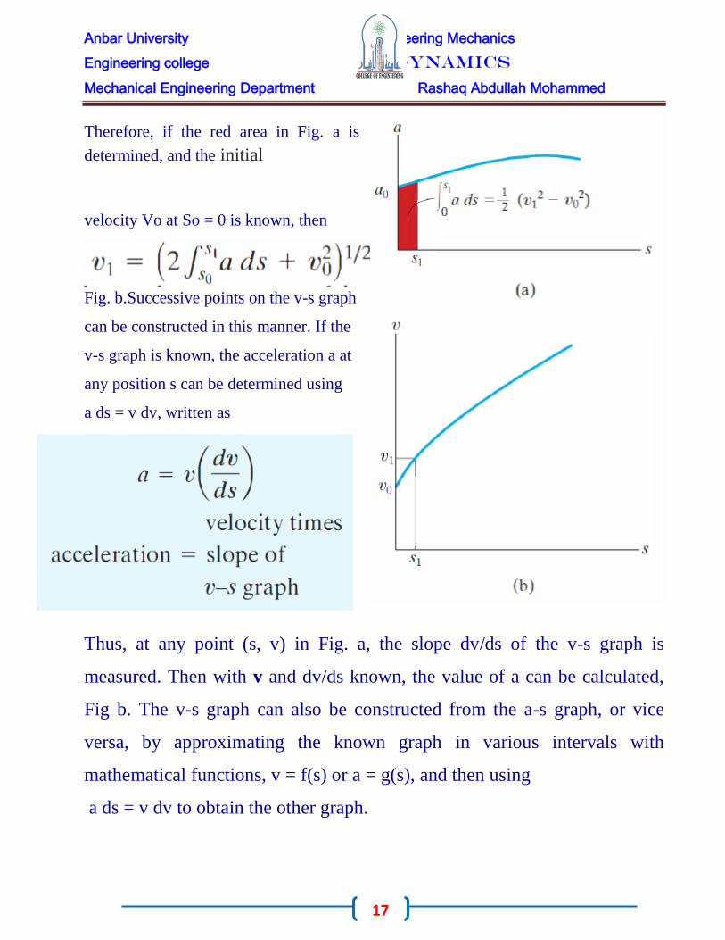
Therefore, if the red area in Fig. a is
determined, and the initial
velocity Vo at So = 0 is known, then
Fig. b.Successive points on the v-s graph
can be constructed in this manner. If the
v-s graph is known, the acceleration a at
any position s can be determined using
a ds = v dv, written as
Thus, at any point (s, v) in Fig. a, the slope dv/ds of the v-s graph is
measured. Then with v and dv/ds known, the value of a can be calculated,
Fig b. The v-s graph can also be constructed from the a-s graph, or vice
versa, by approximating the known graph in various intervals with
mathematical functions, v = f(s) or a = g(s), and then using
a ds = v dv to obtain the other graph.

Anbar University Engineering Mechanics
Engineering college Dynamics
Mechanical Engineering Department Rashaq Abdullah Mohammed
18
EXA M P L E -1-

Anbar University Engineering Mechanics
Engineering college Dynamics
Mechanical Engineering Department Rashaq Abdullah Mohammed
19
EXA M P L E -2-

Anbar University Engineering Mechanics
Engineering college Dynamics
Mechanical Engineering Department Rashaq Abdullah Mohammed
20

Anbar University Engineering Mechanics
Engineering college Dynamics
Mechanical Engineering Department Rashaq Abdullah Mohammed
21
EXA M P L E -3-
PROPLEMS:-

Anbar University Engineering Mechanics
Engineering college Dynamics
Mechanical Engineering Department Rashaq Abdullah Mohammed
22
Q1/ The particle travels along a straight track such that its position is
described by the s-t graph. Construct the v-t graph for the same time
interval.
Q2/ The sports car travels along a straight road such that its position is described by
the graph. Construct the v-t and a-t graphs for the time interval 0 ≤ t ≥10 s.
Q3/ The
Anbar University Engineering Mechanics
Engineering college Dynamics
Mechanical Engineering Department Rashaq Abdullah Mohammed
23
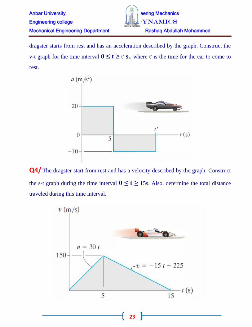
dragster starts from rest and has an acceleration described by the graph. Construct the
v-t graph for the time interval 0 ≤ t ≥ t' s., where t' is the time for the car to come to
rest.
Q4/ The dragster start from rest and has a velocity described by the graph. Construct
the s-t graph during the time interval 0 ≤ t ≥ 15s. Also, determine the total distance
traveled during this time interval.

Anbar University Engineering Mechanics
Engineering college Dynamics
Mechanical Engineering Department Rashaq Abdullah Mohammed
24
Q5/ A two-stage missile is fired vertically from rest with the acceleration shown. In
15 s the first stage A burns out and the second stage B ignites. Plot the v-t and s-t
graphs which describe the two-stage motion of the missile for 0 ≤ t ≥ 20 s.
Q6/ A motorcyclist at A is traveling at 60 ft/s when he wishes to pass the truck T
which is traveling at a constant speed of 60 ft/s. To do so the motorcyclist accelerates
at 6 ft/S2 until reaching a maximum speed of 85 ft/s. If he then maintains this speed,
determine the time needed for him to reach a point located 100 ft in front of the truck.
Draw the v-t and s-t graphs for the motorcycle during this time.

Anbar University Engineering Mechanics
Engineering college Dynamics
Mechanical Engineering Department Rashaq Abdullah Mohammed
25
General Curvilinear Motion
Curvilinear motion occurs when a particle moves along a curved path. Since this path
is often described in three dimensions, vector analysis will be used to formulate the
particle's position, velocity, and acceleration.* In this section the general aspects of
curvilinear motion are discussed, and in subsequent sections we will consider three
types of coordinate systems often used to analyze this motion.
Position. Consider a particle located at a point on a space curve defined by the path
function s(t) Fig a. The position of the particle,
measured from a fixed point o, will be
designated by the position vector ( r= r(t) )
Notice that both the magnitude and direction of
this vector will change as the particle moves
along the curve.
Displacement. Suppose that during a small
time interval Δt the particle moves a
distance Δs along the curve to a new
position, defined by r' = r + Δr, Fig b. The
displacement Δr represents the change in the
particle's position and is determined by
vector subtraction; i.e., Δr = r' - r.

Anbar University Engineering Mechanics
Engineering college Dynamics
Mechanical Engineering Department Rashaq Abdullah Mohammed
26
Velocity. During the time Δt the average velocity of the particle is
Thus, the speed can be obtained by differentiating the
path function s with respect to time.
Acceleration. If the particle has a
velocity v at time t and a
velocity v' = v + Δv at
t + Δt, Fig. d, then the average acceleration of the
particle during the time interval
Anbar University Engineering Mechanics
Engineering college Dynamics
Mechanical Engineering Department Rashaq Abdullah Mohammed
27
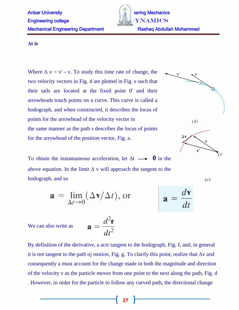
Δt is
Where Δ v = v' - v. To study this time rate of change, the
two velocity vectors in Fig. d are plotted in Fig. e such that
their tails are located at the fixed point 0' and their
arrowheads touch points on a curve. This curve is called a
hodograph, and when constructed, it describes the locus of
points for the arrowhead of the velocity vector in
the same manner as the path s describes the locus of points
for the arrowhead of the position vector, Fig. a.
To obtain the instantaneous acceleration, let Δt 0 in the
above equation. In the limit Δ v will approach the tangent to the
hodograph, and so
We can also write as
By definition of the derivative, a acts tangent to the hodograph, Fig. f, and, in general
it is not tangent to the path oj motion, Fig. g. To clarify this point, realize that Δv and
consequently a must account for the change made in both the magnitude and direction
of the velocity v as the particle moves from one point to the next along the path, Fig. d
. However, in order for the particle to follow any curved path, the directional change

Anbar University Engineering Mechanics
Engineering college Dynamics
Mechanical Engineering Department Rashaq Abdullah Mohammed
28
always "swings" the velocity vector toward the "inside" or "concave side" of the path,
and therefore a cannot remain tangent to the path. In summary, v is always tangent to
the path and a is always tangent to the hodograph.
Curvilinear Motion: Rectangular Components
Occasionally the motion of a particle can best be described along a path that can be
expressed in terms of its x, y, z coordinates.
Position. If the particle is at point (x, y, z) on the curved path s shown in Fig a, then its
location is defined by the position vector
When the particle moves, the x, y, z
components of r will be functions of time; i.e.,

Anbar University Engineering Mechanics
Engineering college Dynamics
Mechanical Engineering Department Rashaq Abdullah Mohammed
29
X = x(t), y = y(t), z = z(t), so that r = (t).At any instant the magnitude of r is defined
by the Eq.
And the direction of r is specified by the unit vector ur = r/ r.
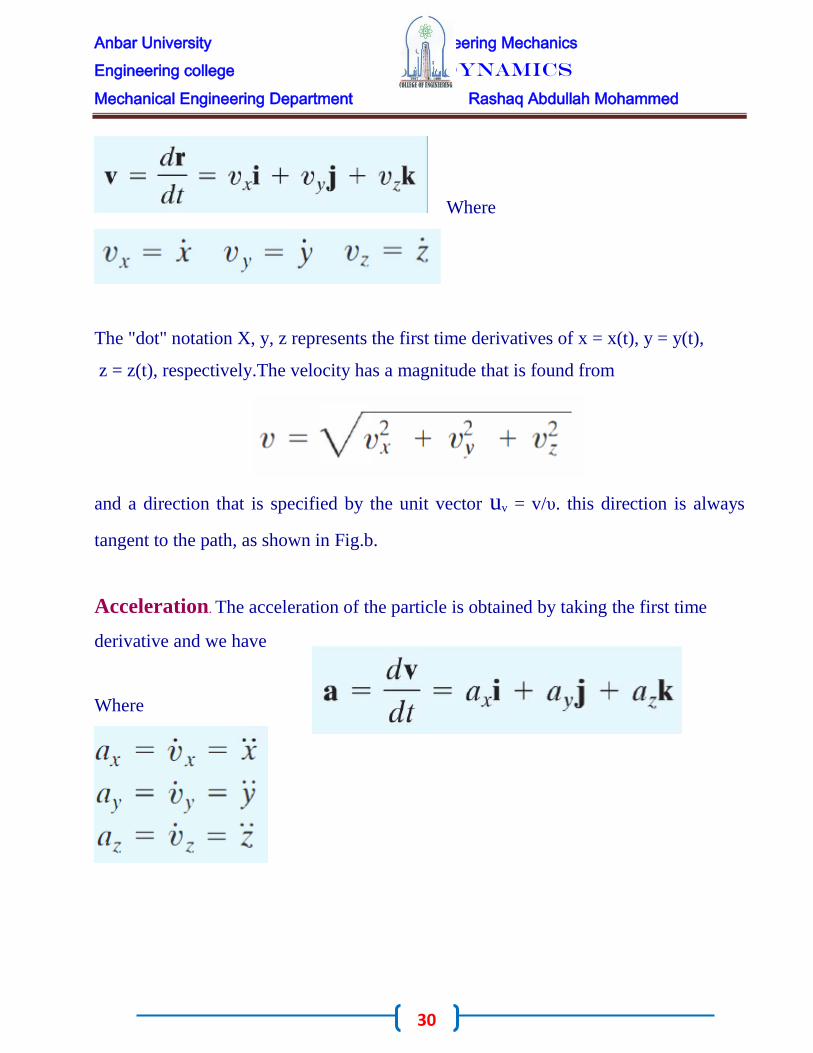
Velocity. The first time derivative of r yields the velocity of the particle. Hence,
When taking this derivative, it is
necessary to account for changes in both
the magnitude and direction of each of
the vector's components. For example,
the derivative of the i component of r is
The second term on the right side is zero, provided the x, y, z reference frame is fixed,
and therefore the direction (and the magnitude) of i does not change with time.
Differentiation of the j and k components may be carried out in a similar manner,
which yields the final result,
Anbar University Engineering Mechanics
Engineering college Dynamics
Mechanical Engineering Department Rashaq Abdullah Mohammed
30
Where
The "dot" notation X, y, z represents the first time derivatives of x = x(t), y = y(t),
z = z(t), respectively.The velocity has a magnitude that is found from
and a direction that is specified by the unit vector uv = v/υ. this direction is always
tangent to the path, as shown in Fig.b.
Acceleration. The acceleration of the particle is obtained by taking the first time
derivative and we have
Where

Anbar University Engineering Mechanics
Engineering college Dynamics
Mechanical Engineering Department Rashaq Abdullah Mohammed
31
and a direction specified by the unit vector Ua = a/ ɑ , Since a represents the time rate
of change in both the magnitude and direction of the velocity, in general a will not be
tangent to the path, Fig. C.
Anbar University Engineering Mechanics
Engineering college Dynamics
Mechanical Engineering Department Rashaq Abdullah Mohammed
32
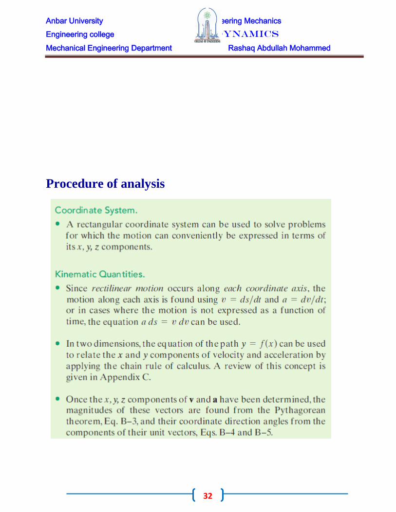
Procedure of analysis

Anbar University Engineering Mechanics
Engineering college Dynamics
Mechanical Engineering Department Rashaq Abdullah Mohammed
33
EXA M P L E-1-

Anbar University Engineering Mechanics
Engineering college Dynamics
Mechanical Engineering Department Rashaq Abdullah Mohammed
34

Anbar University Engineering Mechanics
Engineering college Dynamics
Mechanical Engineering Department Rashaq Abdullah Mohammed
35
EXA M P L E-2-

Anbar University Engineering Mechanics
Engineering college Dynamics
Mechanical Engineering Department Rashaq Abdullah Mohammed
36
Motion of a Projectile
The free-flight motion of a projectile is often studied in terms of its rectangular
components. To illustrate the kinematic analysis, consider a projectile launched at
point (xo, Yo), with an initial velocity of vo, having components (vo)x and (vo)y, Fig.
below . When air resistance is neglected, the only force acting on the projectile is its
weight, which causes the projectile to have a constant downward acceleration of
approximately

Anbar University Engineering Mechanics
Engineering college Dynamics
Mechanical Engineering Department Rashaq Abdullah Mohammed
37
Recall that the last equation can be formulated on the basis of eliminating the time t
from the first two equations, and therefore only two of the above three equations are
independent of one another.
To summarize, problems involving the motion of a projectile can have at most
three unknowns since only three independent equations can be written; that is, one
equation in the horizontal direction and two in the vertical direction. Once Vx and Vy
are obtained, the resultant velocity v, which is always tangent to the path, can be
determined by the vector sum.
Procedure of Analysis
Coordinate System .
• Establish the fixed x, y coordinate axes and sketch the trajectory of the
particle. Between any two points on the path specify the given problem data and
identify the three unknowns. In all cases the acceleration of gravity acts downward and

Anbar University Engineering Mechanics
Engineering college Dynamics
Mechanical Engineering Department Rashaq Abdullah Mohammed
38
equals 9.81 m/s2 or 32.2 ft/s2. The particle's initial and final velocities should be
represented in terms of their x and y components.
• Remember that positive and negative position, velocity, and acceleration
components always act in accordance with their associated coordinate directions.
Kinematic Equations.
• Depending upon the known data and what is to be determined, a choice should
be made as to which three of the following four equations should be applied between
the two points on the path to obtain the most direct solution to the problem

Anbar University Engineering Mechanics
Engineering college Dynamics
Mechanical Engineering Department Rashaq Abdullah Mohammed
39
EXA M P L E-1-

Anbar University Engineering Mechanics
Engineering college Dynamics
Mechanical Engineering Department Rashaq Abdullah Mohammed
40
EXA M P L E-2-

Anbar University Engineering Mechanics
Engineering college Dynamics
Mechanical Engineering Department Rashaq Abdullah Mohammed
41
EXA M P L E-3-

Anbar University Engineering Mechanics
Engineering college Dynamics
Mechanical Engineering Department Rashaq Abdullah Mohammed
42
Problems:-
Q1/ A particle is traveling along the
straight path. If its position along the x
axis is x = (8t) m, where t is in seconds,
determine its speed when t = 2 s.
Q2/ The ball is kicked from point A
with the initial velocity v A = 10 m/s.
Determine the range R, and the speed
when the ball strikes the ground.
Q3/ A ball is thrown from A. I f i t i s
required to clear the wall at B, determine
the minimum magnitude of its initial
velocity VA.
Q4/ Determine the speed at which
the basketball at A must be thrown
at the angle of 30° so that it makes
it to the basket at B.

Anbar University Engineering Mechanics
Engineering college Dynamics
Mechanical Engineering Department Rashaq Abdullah Mohammed
43
Q5/ The van travel over the hill
described by y = (- 1 .5(10-3) x2 + 15) ft.
If it has a constant speed of 75 ft/s,
determine the x and y components of
the van's velocity and acceleration when
x = 5 0 ft.
Q6/ The skateboard rider leaves the
ramp at A with an initial velocity υ
A at a 30° angle. If he strikes the
ground at B, determine v A and the
time of flight
Q7/ A boy throws a ball at o in the air
with a speed Vo at an angle θ1. If he
then throws another ball with the
same speed Vo at an angle θ2 < θ1,
determine the time between the
throws so that the balls collide in mid
air at B.
Q8/ The boy a t A attempts to throw a
ball over the . roof of a barn with an
initial speed of υA = 15 m/s.
Determine the angle θA at which the
ball must be thrown so that it reaches
its maximum height at C. Also, find
the distance d where the boy should
stand to make the throw.

Anbar University Engineering Mechanics
Engineering college Dynamics
Mechanical Engineering Department Rashaq Abdullah Mohammed
44
Absolute Dependent Motion Analysis of Two Particles
In some types of problems the motion of one particle will depend on the corresponding
motion of another particle. This dependency commonly occurs if the particles, here
represented by blocks, are interconnected by inextensible cords which are wrapped
around pulleys. For example, the movement of block A downward along the inclined
plane in Fig.
will cause a corresponding movement of block B up the other incline. We can show
this mathematically by first specifying the location of the blocks using position
coordinates SA and SB. Note that each of the coordinate axes is (1) measured from a
fixed point (o) or fixed datum line, (2) measured along each inclined plane in the
direction of motion of each block, and (3) has a positive sense from C to A and D to B.
If the total cord length is lT, the two position coordinates are related by the equation
Here lCD is the length of the cord passing over arc CD. Taking the time derivative of
this expression, realizing that lCD and lT remain constant, while SA and SB measure the
segments of the cord that change in length. We have

Anbar University Engineering Mechanics
Engineering college Dynamics
Mechanical Engineering Department Rashaq Abdullah Mohammed
45
The negative sign indicates that when block A has a velocity downward, i.e., in the
direction of positive SA, it causes a corresponding upward velocity of block B; i.e., B
moves in the negative SB direction. In a similar manner, time differentiation of the
velocities yields the relation between the accelerations, i.e.,
A more complicated example is shown in Fig. a. In this
case, the position of block A is specified by SA, and the
position of the end of the cord from which block B is
suspended is defined by SB.
As above, we have chosen position coordinates which (1)
have their origin at fixed points or datums, (2) are
measured in the direction of motion of each block, and (3)
are positive to the right for SA and positive downward for
SB. During the motion, the length of the red colored
segments of the cord in Fig a. remains constant. If l
represents the total length of cord minus these segments, then the position coordinates
can be related by the equation
Since l and h are
constant during the
motion, the two time
derivatives yield

Anbar University Engineering Mechanics
Engineering college Dynamics
Mechanical Engineering Department Rashaq Abdullah Mohammed
46
Hence, when B moves downward (+SB), A moves to the left (-SA) with twice the
motion
This example can also be worked by defining the position
of block B from the center of the bottom pulley (a fixed
point), Fig. b. In this case
EXA M P L E-1-
Determine the speed of block A in
Fig. if block B has an upward speed
of 6 ft/s.

Anbar University Engineering Mechanics
Engineering college Dynamics
Mechanical Engineering Department Rashaq Abdullah Mohammed
47
EXA M P L E-2-
Determine the speed of block B in
Fig. if the end of the cord at A is
pulled down with a speed of 2 m/s.

Anbar University Engineering Mechanics
Engineering college Dynamics
Mechanical Engineering Department Rashaq Abdullah Mohammed
48
EXA M P L E-2- A man at A is hoisting a safe S as shown in
Fig. by walking to the right with a constant
velocity VA=0.5m/s. Determine the velocity
and acceleration of the safe when it reaches

Anbar University Engineering Mechanics
Engineering college Dynamics
Mechanical Engineering Department Rashaq Abdullah Mohammed
49
the elevation of 10 m. The rope is 30 m long and passes over a small pulley
at D.

Anbar University Engineering Mechanics
Engineering college Dynamics
Mechanical Engineering Department Rashaq Abdullah Mohammed
50

Anbar University Engineering Mechanics
Engineering college Dynamics
Mechanical Engineering Department Rashaq Abdullah Mohammed
51
Relative-Motion of Two Particles
Using Translating Axes
Position. Consider particles A and B, which move along the arbitrary paths shown in
Fig. 12-42. The absolute position of each particle, r A and rB , is measured from the
common origin o of the fixed x,y,z reference
frame. The origin of a second frame of
reference x', y ' , z ' is attached to and move
with particle A. The axes of this frame are
only relative to the fixed frame. The position
of B measured relative to A is denoted by the
relative-position vector rB/A' Using vector
addition, the three vectors shown in Fig. can
be related by the equation
Velocity. An equation that relates the velocities of the particles is determined by
taking the time derivative of the above equation; i.e.,

Anbar University Engineering Mechanics
Engineering college Dynamics
Mechanical Engineering Department Rashaq Abdullah Mohammed
52
Here VB = drB/ dt and vA = drA/ dt refer to absolute velocities, since they are observed
from the fixed frame; whereas the relative velocity vB/A = drB/A/dt is observed from the
translating frame. It is important to note that since the x', y', z ' axes translate, the
components of rB/A will not change direction and therefore the time derivative of these
components will only have to account for the change in their magnitudes. Above
Equation therefore states that the velocity of B is equal to the velocity of A plus
(vectorially) the velocity of "B with respect to A ," as measured by the translating
observer fixed in the x', y', z ' reference frame.
Acceleration. The time derivative of the Eq.
yields a similar vector relation between the absolute and
relative accelerations of particles A and B
EXAMPLE-1-
A train travels at a constant speed of 60 mi/h,
crosses over a road as shown in Fig. a. If the
automobile A is traveling at 45 mi/h along the
road, determine the magnitude and direction of
the velocity of the train relative to the
automobile

Anbar University Engineering Mechanics
Engineering college Dynamics
Mechanical Engineering Department Rashaq Abdullah Mohammed
53
Note that the vector addition shown in Fig. b
indicates the correct sense for VT/A’ This figure
anticipates the answer and can be used to check it.

Anbar University Engineering Mechanics
Engineering college Dynamics
Mechanical Engineering Department Rashaq Abdullah Mohammed
54
Anbar University Engineering Mechanics
Engineering college Dynamics
Mechanical Engineering Department Rashaq Abdullah Mohammed
55
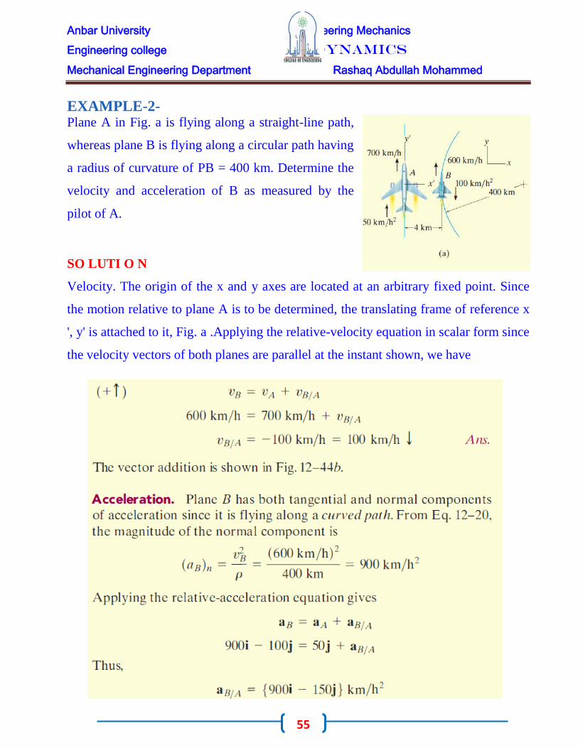
EXAMPLE-2- Plane A in Fig. a is flying along a straight-line path,
whereas plane B is flying along a circular path having
a radius of curvature of PB = 400 km. Determine the
velocity and acceleration of B as measured by the
pilot of A.
SO LUTI O N
Velocity. The origin of the x and y axes are located at an arbitrary fixed point. Since
the motion relative to plane A is to be determined, the translating frame of reference x
', y' is attached to it, Fig. a .Applying the relative-velocity equation in scalar form since
the velocity vectors of both planes are parallel at the instant shown, we have

Anbar University Engineering Mechanics
Engineering college Dynamics
Mechanical Engineering Department Rashaq Abdullah Mohammed
56

Anbar University Engineering Mechanics
Engineering college Dynamics
Mechanical Engineering Department Rashaq Abdullah Mohammed
57
PROBLRMS
Q1/ The mine car C is being pulled up the
incline using the motor M and the rope-and-
pulley arrangement shown. Determine the
speed vp at which a point P on the cable must be
traveling toward the motor to move the car up
the plane with a constant speed of υ = 2 m/s.
Q2/ Determine the speed of the elevator if each motor
draws in the cable with a constant speed of 5 m/s.
Anbar University Engineering Mechanics
Engineering college Dynamics
Mechanical Engineering Department Rashaq Abdullah Mohammed
58
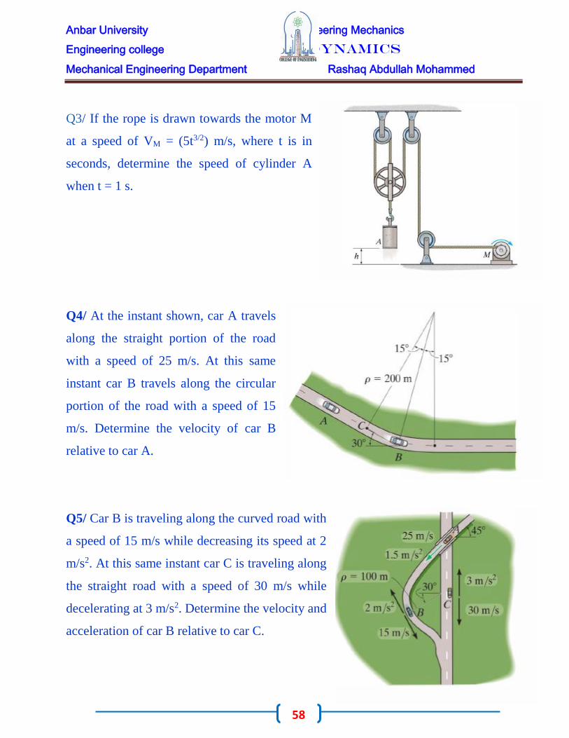
Q3/ If the rope is drawn towards the motor M
at a speed of VM = (5t3/2) m/s, where t is in
seconds, determine the speed of cylinder A
when t = 1 s.
Q4/ At the instant shown, car A travels
along the straight portion of the road
with a speed of 25 m/s. At this same
instant car B travels along the circular
portion of the road with a speed of 15
m/s. Determine the velocity of car B
relative to car A.
Q5/ Car B is traveling along the curved road with
a speed of 15 m/s while decreasing its speed at 2
m/s2. At this same instant car C is traveling along
the straight road with a speed of 30 m/s while
decelerating at 3 m/s2. Determine the velocity and
acceleration of car B relative to car C.
Anbar University Engineering Mechanics
Engineering college Dynamics
Mechanical Engineering Department Rashaq Abdullah Mohammed
59
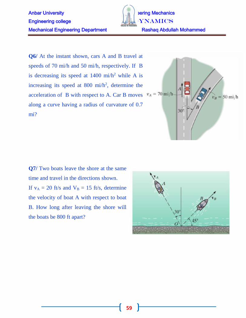
Q6/ At the instant shown, cars A and B travel at
speeds of 70 mi/h and 50 mi/h, respectively. If B
is decreasing its speed at 1400 mi/h2 while A is
increasing its speed at 800 mi/h2, determine the
acceleration of B with respect to A. Car B moves
along a curve having a radius of curvature of 0.7
mi?
Q7/ Two boats leave the shore at the same
time and travel in the directions shown.
If vA = 20 ft/s and VB = 15 ft/s, determine
the velocity of boat A with respect to boat
B. How long after leaving the shore will
the boats be 800 ft apart?

Anbar University Engineering Mechanics
Engineering college Dynamics
Mechanical Engineering Department Rashaq Abdullah Mohammed
60
Curvilinear Motion Normal and
Tangential Components
When the path along which a particle travels is known, then it is often
convenient to describe the motion using n and t coordinate axes which act normal and
tangent to the path, respectively, and at the instant considered have their origin located
at the particle
Planar Motion . Consider the particle shown in Fig. a, which moves in a plane along a
fixed curve, such that at a given instant it is at position s, measured from point O.
We will now consider a coordinate system
that has its origin at a fixed point on the
curve, and at the instant considered this
origin happens to coincide with the location
of the particle. The t axis is tangent to the
curve at the point and is positive in the
direction of increasing s. We will designate
this positive direction with the unit vector Ut
• A unique choice for the normal axis can be made by noting that geometrically the
curve is constructed from a series of
differential arc segments ds, Fig. b.
Each segment ds is formed from the arc of an
associated circle having a radius of curvature ρ
(rho) and center of curvature 0 ' . The normal

Anbar University Engineering Mechanics
Engineering college Dynamics
Mechanical Engineering Department Rashaq Abdullah Mohammed
61
axis n is perpendicular to the t axis with its positive sense directed toward the center of
curvature 0 ' , Fig. a. This positive direction, which is always on the concave side of
the curve, will be designated by the unit vector Un ' The plane which contains the n
and t axes is referred to as the embracing or osculating plane, and in this case it is
fixed in the plane of motion.
Velocity. Since the particle moves, s is a function
of time. the particle's velocity v has a direction that
is always tangent to the path, Fig. c, and a
magnitude that is determined by taking the time
derivative of the path function s = s(t), i.e., v = ds/
dt (Hence)
Acceleration. The acceleration of the particle is the time rate of
change of the velocity. Thus,
In order to determine the time
derivative Ut , note that as the particle
moves along the arc ds in time dt, Ut
preserves its magnitude of unity;

Anbar University Engineering Mechanics
Engineering college Dynamics
Mechanical Engineering Department Rashaq Abdullah Mohammed
62
however, its direction changes, and becomes u; , Fig.d. As shown in Fig. e, we require
Ut = Uf + dut. Here dut stretches between the arrowheads of Ut and ut, which lie on an
infinitesimal arc of radius Uf = 1. Hence, dUt has a magnitude of
dUf = (1) dθ, and its direction is defined by Un' Consequently, dUt = dθ Un, and
therefore the time derivative becomes Ut = θUn. Since ds = ρd dθ, Fig. d, then dθ = s/ρ,
and therefore.
can be written as the sum of its two components,

Anbar University Engineering Mechanics
Engineering college Dynamics
Mechanical Engineering Department Rashaq Abdullah Mohammed
63
These two mutually perpendicular components are shown in Fig. f. Therefore, the
magnitude of acceleration is the positive value of
PROCEDURE OF ANALYSIS

Anbar University Engineering Mechanics
Engineering college Dynamics
Mechanical Engineering Department Rashaq Abdullah Mohammed
64
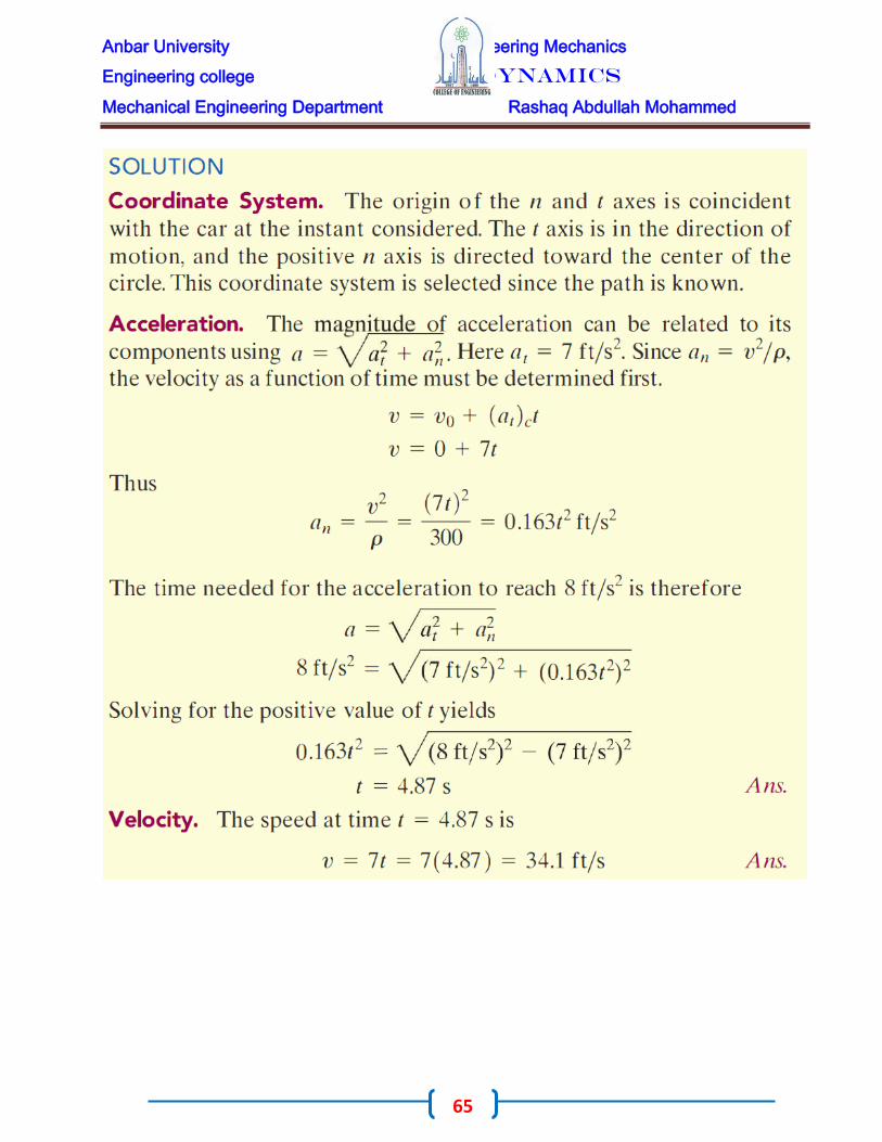
EXA M P L E -1-
A race car C travels around the horizontal circular track that has a radius of 300 ft, Fig.
If the car increases its speed at a constant rate of 7 ft/S2, starting from rest, determine
the time needed for it to reach an acceleration of 8 ft/S2. What is its speed at this
instant
Anbar University Engineering Mechanics
Engineering college Dynamics
Mechanical Engineering Department Rashaq Abdullah Mohammed
65

Anbar University Engineering Mechanics
Engineering college Dynamics
Mechanical Engineering Department Rashaq Abdullah Mohammed
66
EXA M P L E -1-
EXA M P L E -2- The boxes in Fig. 12-29a travel along the industrial conveyor. If a box as in Fig.
b starts from rest at A and increases its speed such that at = (0.2t) m/s2
, where t is in seconds, determine the magnitude of its acceleration when it arrives at
point B?

Anbar University Engineering Mechanics
Engineering college Dynamics
Mechanical Engineering Department Rashaq Abdullah Mohammed
67

Anbar University Engineering Mechanics
Engineering college Dynamics
Mechanical Engineering Department Rashaq Abdullah Mohammed
68
PROBLEMS :-
Q1/ When designing a highway curve it is required that cars traveling at a constant
speed of 25 m/s must not have an acceleration that exceeds 3 m/s2. Determine the
Minimum radius of curvature of the curve?
Q2/ Starting from rest, the motorboat
travels around the circular path, ρ = 50 m,
at a speed v = (0.2t2) m/s, where t is in
seconds. Determine the magnitudes of the
boat's velocity and acceleration at the
instant t = 3 s.
Q3/ The car travels along the circular path
such that its speed is increased by at = (0.5et)
m/s2, where t is in seconds. Determine the
magnitudes of its velocity and acceleration
after the car has traveled s = 18 m starting
from rest. Neglect the size of the car ?

Anbar University Engineering Mechanics
Engineering college Dynamics
Mechanical Engineering Department Rashaq Abdullah Mohammed
69
Q4/ The train passes point A with a
speed of 30 m/s and begins to
decrease its speed at a constant rate of
at = - 0.25 m/s2. Determine the
magnitude of the acceleration of the
train when it reaches point B, where
SAB = 412 m?
Kinetics of a Particle
Force and Acceleration
Newton's Second Law of Motion:-
Kinetics is a branch of dynamics that deals with the relationship between the
change in motion of a body and the forces that cause this change. The basis for kinetics
is Newton's second law, which states that when an unbalanced force acts on a particle,
the particle will accelerate in the direction of the force with a magnitude that is
proportional to the force. This law can be verified experimentally by applying a known
Unbalanced force F to a particle, and then measuring the acceleration a. Since
the force and acceleration are directly proportional, the constant of proportionality, m,
may be determined from the ratio m = F / a. This positive scalar m is called the mass

Anbar University Engineering Mechanics
Engineering college Dynamics
Mechanical Engineering Department Rashaq Abdullah Mohammed
70
of the particle. Being constant during any acceleration, m provides a quantitative
measure of the resistance of the particle to a change in its velocity that is its inertia. If
the mass of the particle is m, Newton's second law of motion may be written in
mathematical form as.
Newton's Law of Gravitational Attraction. Shortly after formulating his three
laws of motion, Newton postulated a law governing the mutual attraction between any
two particles. In mathematical form this law can be expressed as.
Where
In the case of a particle located at or near the surface of the earth, the only gravitational
force having any sizable magnitude is that between the earth and the particle. This
Anbar University Engineering Mechanics
Engineering college Dynamics
Mechanical Engineering Department Rashaq Abdullah Mohammed
71
force is termed the "weight" and, for our purpose, it will be the only gravitational force
considered. From a above Eq, we can develop a general expression for finding the
weight W of a particle having a mass ml = m. Let m2 = Me be the mass of the earth and
r the distance between the earth's center and the particle. Then, if g = GMe/r2, we have
By comparison with F = ma, we term g the acceleration due to gravity.
For most engineering calculations g is a point on the surface of the earth at sea
level, and at a latitude of 45°, which is considered the "standard location." Here
the values g = 9.81 m/s2 = 32.2 ft/s2 will be used for calculations

Anbar University Engineering Mechanics
Engineering college Dynamics
Mechanical Engineering Department Rashaq Abdullah Mohammed
72
The Equation of Motion
When more than one force acts on a particle, the resultant force is determined by a
vector summation of all the forces; i.e., FR = ∑F. For this more general case, the
equation of motion may be written as
To illustrate application of this equation, consider
the particle shown in Fig. a, which has a mass m
and is subjected to the action of two forces, Fl and
F2 • We can graphically account for the

Anbar University Engineering Mechanics
Engineering college Dynamics
Mechanical Engineering Department Rashaq Abdullah Mohammed
73
magnitude and direction of each force acting on the particle by drawing the particle's
free-body diagram, Fig b. Since the resultant of these forces produces the vector rna,
its magnitude and direction can be represented graphically on the kinetic diagram,
shown in Fig. c. The equal sign written between the diagrams symbolizes the graphical
equivalency between the free-body diagram and the kinetic diagram; i.e., ∑F = ma.t In
particular, note that if FR = ∑F = 0, then the acceleration is also zero, so that the
particle will either remain at rest or move along a estqruaiilgibhrt-iluinme, path with
constant velocity. Such are the conditions of static Newton's first law of motion.
Inertial Reference Frame. When applying the equation of motion, it is
important that the acceleration of the particle be measured with respect reference frame
that either fixed or translate with a constant velocity In this way, the observer will not
accelerate and measurements of the particle's
acceleration will be the same from any reference of
this type. Such a frame of reference is commonly
known as a Newtonian or inertial reference frame
Anbar University Engineering Mechanics
Engineering college Dynamics
Mechanical Engineering Department Rashaq Abdullah Mohammed
74
When studying the motions of rockets and satellites, it is justifiable to consider the
inertial reference frame as fixed to the stars, whereas dynamics problems concerned
with motions on or near the surface of the earth may be solved by using an inertial
frame which is assumed fixed to the earth. Even though the earth both rotates about its
own axis and revolves about the sun, the accelerations created by these rotations are
relatively small and so they can be neglected for most applications.
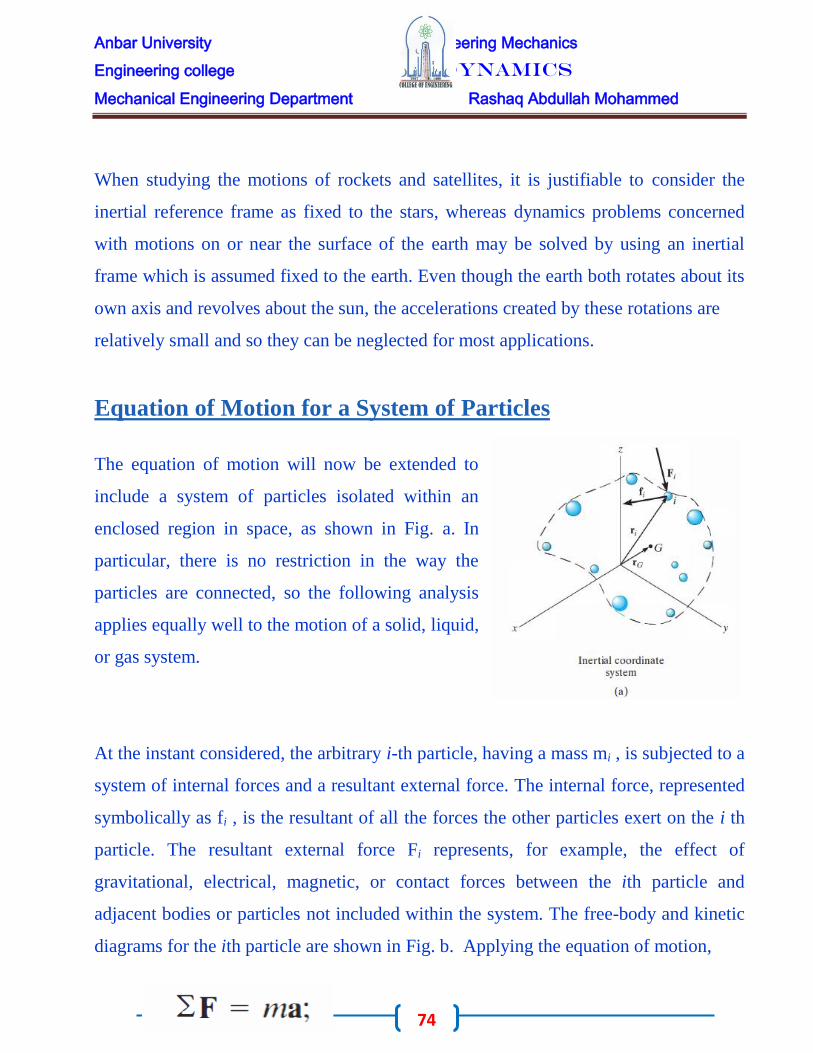
Equation of Motion for a System of Particles
The equation of motion will now be extended to
include a system of particles isolated within an
enclosed region in space, as shown in Fig. a. In
particular, there is no restriction in the way the
particles are connected, so the following analysis
applies equally well to the motion of a solid, liquid,
or gas system.
At the instant considered, the arbitrary i-th particle, having a mass mi , is subjected to a
system of internal forces and a resultant external force. The internal force, represented
symbolically as fi , is the resultant of all the forces the other particles exert on the i th
particle. The resultant external force Fi represents, for example, the effect of
gravitational, electrical, magnetic, or contact forces between the ith particle and
adjacent bodies or particles not included within the system. The free-body and kinetic
diagrams for the ith particle are shown in Fig. b. Applying the equation of motion,

Anbar University Engineering Mechanics
Engineering college Dynamics
Mechanical Engineering Department Rashaq Abdullah Mohammed
75
When the equation of motion is applied to each
of the other particles of the system, similar
equations will result. And, if all these equations
are added together vectorially, we obtain
The summation of the internal forces, if carried out, will equal zero, since internal
forces between any two particles occur in equal but opposite collinear pairs.
Consequently, only the sum of the external forces will remain, and therefore the
equation of motion, written for the system of particles, becomes
If rG is a position vector which locates the center of mass G of the particles, Fig. a,
then by definition of the center of mass, m rG = ∑.miri, where m = ∑mi is the total
mass of all the particles. Differentiating this equation twice with respect to time,
assuming that no mass is entering or leaving the system, yields
Anbar University Engineering Mechanics
Engineering college Dynamics
Mechanical Engineering Department Rashaq Abdullah Mohammed
76
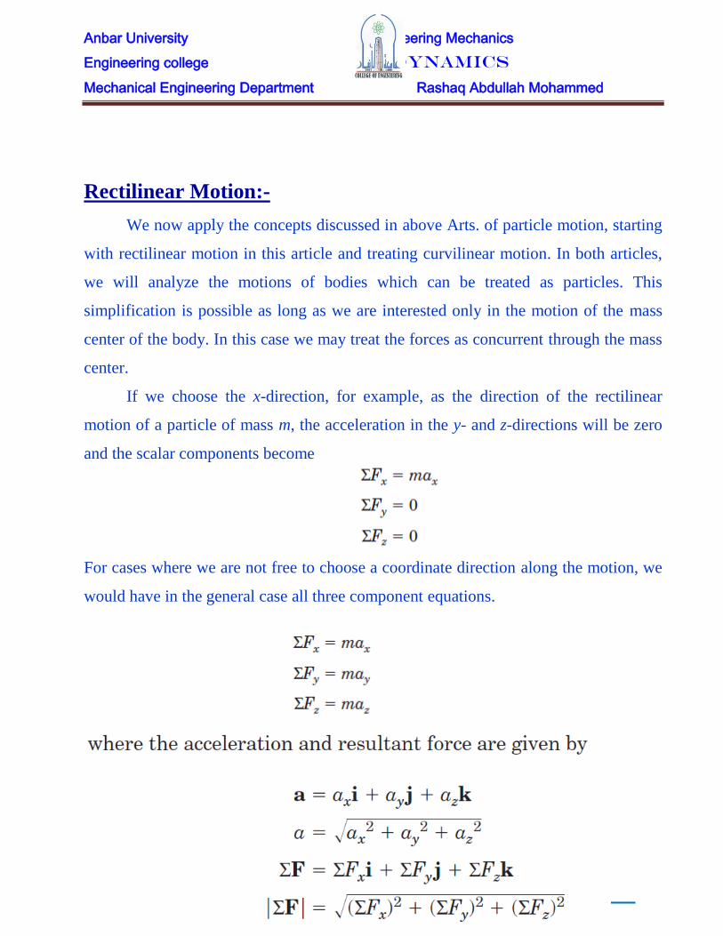
Rectilinear Motion:-
We now apply the concepts discussed in above Arts. of particle motion, starting
with rectilinear motion in this article and treating curvilinear motion. In both articles,
we will analyze the motions of bodies which can be treated as particles. This
simplification is possible as long as we are interested only in the motion of the mass
center of the body. In this case we may treat the forces as concurrent through the mass
center.
If we choose the x-direction, for example, as the direction of the rectilinear
motion of a particle of mass m, the acceleration in the y- and z-directions will be zero
and the scalar components become
For cases where we are not free to choose a coordinate direction along the motion, we
would have in the general case all three component equations.

Anbar University Engineering Mechanics
Engineering college Dynamics
Mechanical Engineering Department Rashaq Abdullah Mohammed
77
EXA M P L E-1 -
A 75-kg man stands on a spring scale in an elevator. During
the first 3 seconds of motion from rest, the tension T in the
hoisting cable is 8300 N. Find the reading R of the scale in
newtons during this interval and the upward velocity v of the
elevator at the end of the 3 seconds. The total mass of the
elevator, man, and scale is 750 kg
.
EXA
M P L
E-2 –
A
small
inspecti
on car
with a
mass of
200 kg
runs
along

Anbar University Engineering Mechanics
Engineering college Dynamics
Mechanical Engineering Department Rashaq Abdullah Mohammed
78
the fixed overhead cable and is controlled by the attached cable at A. Determine the
acceleration of the car when the control cable is horizontal and under a tension T = 2.4
kN. Also find the total force P exerted by the supporting cable on the wheels.
EXAMPLES -3-
The 250-lb concrete block A is released from rest
in the position shown and pulls the 400-lb log up
the 30_ ramp. If the coefficient of kinetic friction
between the log and the ramp is 0.5, determine
the velocity of the block as it hits the ground at B.

Anbar University Engineering Mechanics
Engineering college Dynamics
Mechanical Engineering Department Rashaq Abdullah Mohammed
79

Anbar University Engineering Mechanics
Engineering college Dynamics
Mechanical Engineering Department Rashaq Abdullah Mohammed
80
EXAMPLE -4

Anbar University Engineering Mechanics
Engineering college Dynamics
Mechanical Engineering Department Rashaq Abdullah Mohammed
81
EXAMPLE -5-

Anbar University Engineering Mechanics
Engineering college Dynamics
Mechanical Engineering Department Rashaq Abdullah Mohammed
82
PROBLEMS
Q1 /The 50-kg crate is projected along the
floor with an initial speed of 7 m/s at x=0 .
The coefficient of kinetic friction is 0.40.
Calculate the time required for the crate to
come to rest and the corresponding distance x
traveled
Q2/ The 50-kg crate of Prob. 1 is now
projected down an incline as shown with an
initial speed of 7 m/s. Investigate the time t
required for the crate to come to rest and the
corresponding distance x traveled if (a) θ=15o
and (b) θ=30o .
Q3/ A spring of stiffness k = 500 N/m is
mounted against the 10-kg block. If the
block is subjected to the force of F = 500 N,
determine its velocity at s = 0.5 m. When s
= 0, the block is at rest and the spring is
uncompressed. The contact surface is
smooth.

Anbar University Engineering Mechanics
Engineering college Dynamics
Mechanical Engineering Department Rashaq Abdullah Mohammed
83
Q4/ If block A and B of mass 10 kg ans 6 kg
respectively, are placed on the inclined plane and
released, determine the force developed in the
link. The coefficients of kinetic friction between
the blocks and the inclined plane are μA = 0.1 and
μB = 0.3. Neglect the mass of the link.
Q5/ Determine the acceleration of the
system and the tension in each cable. The
inclined plane is smooth, and the coefficient
of kinetic friction between the horizontal
surface and block C is (μk)c = 0.2.
Q6/Each of the three barges has a mass of 30
Mg, whereas the tugboat has a mass of 12
Mg. As the barges are being pulled forward
with a constant velocity of 4 m/s, the tugboat
must overcome the frictional resistance of the
water, which is 2 kN for each barge and 1.5
kN for the tugboat. If the cable between A and B breaks, determine the acceleration of
the tugboat
Q7/ The 2-lb collar C fits loosely on the smooth shaft. If the
spring is unstretched when s = 0 and the collar is given a
velocity of 1 5 ft/s, determine the velocity of the collar when
s = 1 ft.

Anbar University Engineering Mechanics
Engineering college Dynamics
Mechanical Engineering Department Rashaq Abdullah Mohammed
84
Equations of Motion Normal and
Tangential Coordinates
When a particle moves along a curved path which is known, the equation of motion for
the particle may be written in the tangential, normal, and bi normal directions, Fig..
Note that there is no motion of the particle in the bi normal direction, since the particle
is constrained to move along the path. We have
This equation is satisfied provided
Recall that at (= dv/ dt) represents the time rate of change in the magnitude of velocity.
So if ∑Ft acts in the direction of motion, the particle's speed will increase, whereas if it
acts in the opposite direction, the particle will slow down. Likewise, an ( = v2 / ρ)
represents the time rate of change in the velocity's direction. It is caused by ∑ Fn ,
which always acts in the positive n direction, i.e., toward the path's center of curvature.
From this reason it is often referred to as the centripetal force

Anbar University Engineering Mechanics
Engineering college Dynamics
Mechanical Engineering Department Rashaq Abdullah Mohammed
85
Example -1-
Determine the banking angle θ for the race
track so that the wheels of the racing cars
shown in Fig. a will not have to depend
upon friction to prevent any car from
sliding up or down the track. Assume the
cars have negligible size, a mass m, and
travel around the curve of radius ρ with a
constant speed υ.
Anbar University Engineering Mechanics
Engineering college Dynamics
Mechanical Engineering Department Rashaq Abdullah Mohammed
86
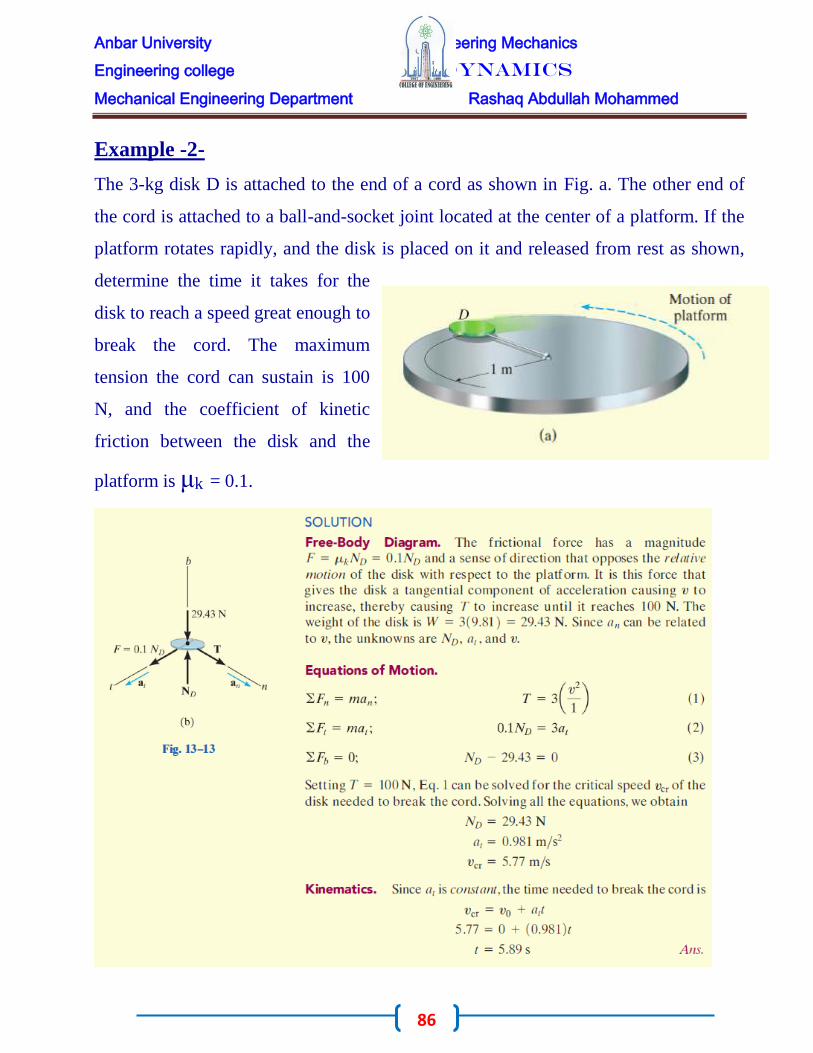
Example -2-
The 3-kg disk D is attached to the end of a cord as shown in Fig. a. The other end of
the cord is attached to a ball-and-socket joint located at the center of a platform. If the
platform rotates rapidly, and the disk is placed on it and released from rest as shown,
determine the time it takes for the
disk to reach a speed great enough to
break the cord. The maximum
tension the cord can sustain is 100
N, and the coefficient of kinetic
friction between the disk and the
platform is μk = 0.1.

Anbar University Engineering Mechanics
Engineering college Dynamics
Mechanical Engineering Department Rashaq Abdullah Mohammed
87
Example -3-

Anbar University Engineering Mechanics
Engineering college Dynamics
Mechanical Engineering Department Rashaq Abdullah Mohammed
88
Problems
Q1/ The 2-kg block B and 15-kg cylinder A are connected
to a light cord that passes through a hole in the center of
the smooth table. If the block travels along a circular path
of radius r = 1.5 m, determine the speed of the block.
Q2/ A man having the mass of 75 kg sits in the chair
which is pin-connected to the frame BC. If the man is
always seated in an upright position, determine the
horizontal and vertical reactions of the chair on the man at
the instant θ= 45°. At this instant he has a speed of 6 m/s,
which is increasing at 0.5 m/s2
Q3/ A spring, having an unstretched length of 2 ft,
has one end attached to the 10-lb ball. Determine
the angle θ of the spring if the ball has a speed of 6
ft/s tangent to the horizontal circular path

Anbar University Engineering Mechanics
Engineering college Dynamics
Mechanical Engineering Department Rashaq Abdullah Mohammed
89
Q4/ The 0.8-Mg car travels over the hill having the shape of a parabola. When the car
is at point A, it is traveling at 9 m/s and increasing its speed at 3 m/s2. Determine both
the resultant normal force and the resultant frictional force that all the wheels of the car
exert on the road at this instant. Neglect the size of the car
Q5/ The 6-kg block is confined to move along the smooth parabolic path. The attached
spring restricts the motion and, due to the roller guide, always remains horizontal as
the block descends. If the spring has a stiffness of k = 10 N/m, and unstretched length
of 0.5 m, determine the normal force of the path
on the block at the instant x = 1 m when the
block has a speed of 4 m/s. Also, what is the
rate of increase in speed of the block at this
point? Neglect the mass of the roller and the
spring.

Anbar University Engineering Mechanics
Engineering college Dynamics
Mechanical Engineering Department Rashaq Abdullah Mohammed
90
Kinetics of a Particle
Work and Energy
The analyze motion of a particle using the concepts of work and energy. The resulting
equation will be useful for solving problems that involve force, velocity, and
displacement. Before we do this, however, we must first define the work of a force.
Specifically, a force F will do work on a particle only when the particle undergoes a
displacement in the direction of the force. For
example, if the force F in Fig. causes the
particle to move along the path s from
position r to a new position r', the
displacement is then dr = r' - r. The magnitude
of dr is ds, the length of the differential
segment along the path. If the angle between
the tails of dr and F is e, Fig. then the work
done by F is a scalar quantity, defined by
By definition of the dot product this equation can also be written as
This result may be interpreted in one of two ways: either as the product of F and the
component of displacement ds cosθ in the direction of the force, or as the product of ds
and the component of force,

Anbar University Engineering Mechanics
Engineering college Dynamics
Mechanical Engineering Department Rashaq Abdullah Mohammed
91
Work of a Varia ble Force.
If the particle acted upon by the force F
undergoes a finite displacement along its path from
r1 to r2 or S1 to S2 , Fig.a, the work of force F is
determined by integration. Provided F and 8 can be
expressed as a function of position, then

Anbar University Engineering Mechanics
Engineering college Dynamics
Mechanical Engineering Department Rashaq Abdullah Mohammed
92
Sometimes, this relation may be obtained by
using experimental data to plot a graph of F
cosθ vs. s. Then the area under this graph
bounded by S1 and S2 represents the total work,
Fig.b.
Work of a Consta nt Force Moving Along a Straight Line.
If the force Fc has a constant magnitude and acts at a constant angle θ from its straight-
line path, Fig. a, then the component of Fc in the direction of displacement is always
Fc cosθ. The work done by Fc when the particle is displaced from Sl to S2 is
determined from Eq. in which case

Anbar University Engineering Mechanics
Engineering college Dynamics
Mechanical Engineering Department Rashaq Abdullah Mohammed
93
Work of a Weight.
Consider a particle of weight W,
which moves up along the path s
shown in Fig. from position Sl to
position S2. At an intermediate point,
the displacement
dr = dxi + dyj + dzk. Since W = -Wj,
we have
Work of a S pring Force.
If an elastic spring is elongated a distance ds, Fig. a,
then the work done by the force that acts on the
attached particle is dU = - Fsds = -ks ds. The work is
negative since Fs acts in the opposite sense to ds. If the
particle displaces from Sl to S2, the work of Fs is then

Anbar University Engineering Mechanics
Engineering college Dynamics
Mechanical Engineering Department Rashaq Abdullah Mohammed
94
This work represents the trapezoidal area under the line Fs = ks, Fig.b.
Examples -1-
The l0-kg block shown in Fig. 14-6a rests on the smooth incline. If the spring is
originally stretched 0.5 m, determine the total work done by all the forces acting on the
block when a horizontal force P = 400 N pushes the block up the plane s = 2 m.

Anbar University Engineering Mechanics
Engineering college Dynamics
Mechanical Engineering Department Rashaq Abdullah Mohammed
95

Anbar University Engineering Mechanics
Engineering college Dynamics
Mechanical Engineering Department Rashaq Abdullah Mohammed
96
Principle of Work and Energy Consider the particle in Fig. which is located on the path defined relative to an inertial
coordinate system. If the particle has a mass m and is subjected to a system of external
forces represented by the resultant F R = ∑F, then
the equation of motion for the particle in the
tangential direction is ∑Ft = mat. Applying the
kinematic equation at = v dv/ds and integrating
both sides, assuming initially that the particle has
a position S = S1 and a speed V = V1 , and later at
S = S2 , V = V2 , we have
From this Fig. note that ∑Ft = ∑ Fcosθ, and since work is defined from Eq., the final
result can be written as
This equation represents the principle of work and energy for the particle. The term on
the left is the sum of the work done by all the forces acting on the particle as the
particle moves from point 1 to point 2. The two terms on the right side, which are of
the form T = ½ mv2, define the particle's final and initial kinetic energy, respectively.
Like work, kinetic energy is a scalar and has units of joules (J) and ft · lb. However,
unlike work, which can be either positive or negative, the kinetic energy is always

Anbar University Engineering Mechanics
Engineering college Dynamics
Mechanical Engineering Department Rashaq Abdullah Mohammed
97
positive, regardless of the direction of motion of the particle. it is often expressed in
the form
which states that the particle's initial kinetic energy plus the work done by all the
forces acting on the particle as it moves from its initial to its final position is equal to
the particle's final kinetic energy. As noted from the derivation, the principle of work
and energy represents an integrated form of ∑Ft = mat, obtained by using the kinematic
equation at = v dv/ds. As a result, this principle will provide a convenient substitution
for ∑Ft = mat when solving those types of kinetic problems which involve force,
velocity, and displacement since these quantities are involved in above Eq. For
application, it is suggested that the following procedure be used.
Work of Friction Caused by Sliding
A special class of problems will now be investigated which requires a careful
application of Eq.
These problems involve cases where a body slides over the
surface of another body in the presence of friction. Consider, for
example, a block which is translating a distance s over a rough
surface as shown in Fig. a.
If the applied force P just balances the resultant frictional force
μk.N, Fig.b then due to equilibrium a constant velocity v is maintained, and one would
expect above Eq. to be applied as
follows:

Anbar University Engineering Mechanics
Engineering college Dynamics
Mechanical Engineering Department Rashaq Abdullah Mohammed
98
Examples -1-
The 3500-lb automobile shown in Fig. a travels down the 10° inclined road at a speed
of 20 ft/s. If the driver jams on the brakes,
causing his wheels to lock, determine how
far s the tires skid on the road. The
coefficient of kinetic friction between the
wheels and the road is μk = 0.5.
Anbar University Engineering Mechanics
Engineering college Dynamics
Mechanical Engineering Department Rashaq Abdullah Mohammed
99
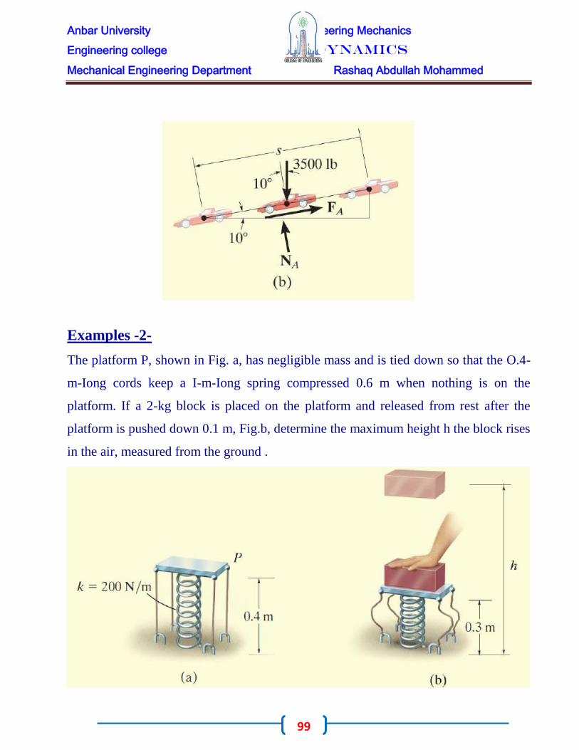
Examples -2-
The platform P, shown in Fig. a, has negligible mass and is tied down so that the O.4-
m-Iong cords keep a I-m-Iong spring compressed 0.6 m when nothing is on the
platform. If a 2-kg block is placed on the platform and released from rest after the
platform is pushed down 0.1 m, Fig.b, determine the maximum height h the block rises
in the air, measured from the ground .

Anbar University Engineering Mechanics
Engineering college Dynamics
Mechanical Engineering Department Rashaq Abdullah Mohammed
100

Anbar University Engineering Mechanics
Engineering college Dynamics
Mechanical Engineering Department Rashaq Abdullah Mohammed
101
Examples -3-
Blocks A and B shown in Fig. a have a mass of 10 kg
and 100 kg, respectively. Determine the distance B
travels when it is released from rest to the point where
its speed becomes 2 m/s.
Work (Free-Body Diagram). As shown on the free-
body diagram of the system, Fig. b, the cable force T and reactions
R 1 and R2 do no work, since these forces represent the reactions at
the supports and consequently they do not move while the blocks
are displaced. The weights both do positive work if we assume both
move downward, in the positive sense of direction of SA and SB'
Principle of Work and Energy. Realizing the blocks are released
from rest, we have

Anbar University Engineering Mechanics
Engineering college Dynamics
Mechanical Engineering Department Rashaq Abdullah Mohammed
102
Examples -4-
The flatbed truck, which carries an 80-kg crate,
starts from rest and attains a speed of 72 km/h in
a distance of 75 m on a level road with constant
acceleration. Calculate the work done by the
friction force acting on the crate during this
interval if the static and kinetic coefficients of
friction between the crate and the truck bed are

Anbar University Engineering Mechanics
Engineering college Dynamics
Mechanical Engineering Department Rashaq Abdullah Mohammed
103
(a) 0.30 and 0.28, respectively, or (b) 0.25 and 0.20, respectively.
Examples -5-
The 50-kg block at A is mounted on rollers so that it
moves along the fixed horizontal rail with negligible
friction under the action of the constant 300-N force
in the cable. The block is released from rest at A,
with the spring to which it is attached extended an
initial amount x1 = 0.233 m. The spring has a

Anbar University Engineering Mechanics
Engineering college Dynamics
Mechanical Engineering Department Rashaq Abdullah Mohammed
104
stiffness k = 80 N/m. Calculate the velocity v of the block as it reaches position B.

Anbar University Engineering Mechanics
Engineering college Dynamics
Mechanical Engineering Department Rashaq Abdullah Mohammed
105
Problems
Q1/ The 1 .5-kg block slides along a smooth plane
and strikes a nonlinear spring with a speed of v = 4
m/s. The spring is termed "nonlinear" because it has
a resistance of Fs = ks2, where k = 900 N/m2.
Determine the speed of the block after it has
compressed the spring s = 0.2 m.
Q2/ The spring in the toy gun have an unscratched
length of 100 mm. It is compressed and locked in the
position shown. When the trigger is pulled, the spring
outstretches 12.5 mm, and the 20-g ball moves along
the barrel. Determine the speed of the ball when it
leaves the gun. Neglect friction.
Q3/ The 2-Mg car has a velocity of V1 = 100 km/h when the driver sees an obstacle in
front of the car. It takes 0.75 s for him to
react and lock the brakes, causing the car
to skid. If the car stops when it has
traveled a distance of 175 m, determine
the coefficient of kinetic friction between the tires and the road.
Q4/ The crate, which has a mass of 100 kg, is
subjected to the action of the two forces. If it is
originally at rest, determine the distance it slides in
order to attain a speed of 6 m/s. The coefficient of

Anbar University Engineering Mechanics
Engineering college Dynamics
Mechanical Engineering Department Rashaq Abdullah Mohammed
106
kinetic friction between the crate and the surface is μk = 0.2.
Q5/ If the 75-kg crate starts from rest at A,
and its speed is 6 m/s when it passes point B,
determine the constant force F exerted on the
cable. Neglect friction and the size of the
pulley.

![Engineering Mechanics - DrChawin.com Engineering Mechanics I [Statics] Lecture 1 Page 1 of 12 Lecture 1: Introduction to Engineering Mechanics Engineering mechanics is the …](https://img.pdfslide.us/doc/110x75/5aa4d6047f8b9ab4788c63da/engineering-mechanics-engineering-mechanics-i-statics-lecture-1-page-1-of-12.jpg)