Embed Size (px)
Citation preview
Anasim CorporationAnasim CorporationTechnology, Methodology, PI-FP Technology, Methodology, PI-FP
Environment and ExamplesEnvironment and Examples
Raj NairRaj NairSept. 22, 2008 Sept. 22, 2008
September 2008September 2008 AnaSIMAnaSIM 22
Presentation OverviewPresentation Overview
Background and historyBackground and history Methodology & technology Methodology & technology
fundamentalsfundamentals --fpfp Customer chip / illustrative examplesCustomer chip / illustrative examples Floorplanning / optimization discussionFloorplanning / optimization discussion
Tool demo (as possible)Tool demo (as possible)
Key messages of interestKey messages of interest
September 2008September 2008 AnaSIMAnaSIM 33
0.1
1
10
100
’71 ’74 ’78 ’85 ’92 ’00 ’04 ’08
Pow
er (
Wat
ts)
40048008
80808085
8086
286
386
486
Pentium®processors
Processor power doubles every ~36 months…
0.1
1
10
100
’71 ’74 ’78 ’85 ’92 ’00 ’04 ’08
Pow
er (
Wat
ts)
40048008
80808085
8086
286
386
486
Pentium®processors
0.1
1
10
100
’71 ’74 ’78 ’85 ’92 ’00 ’04 ’08
Pow
er (
Wat
ts)
40048008
80808085
8086
286
386
486
Pentium®processors
Processor power doubles every ~36 months…
CPU Operating State Currents Time(s)
(Amp)
0.0
+20.00
+40.00
+60.00
+30.00u +30.00u +30.01u +30.01u +30.02u +30.02u +30.03u +30.03u
Sleep
Active
CPU Operating State Currents Time(s)
(Amp)
0.0
+20.00
+40.00
+60.00
+30.00u +30.00u +30.01u +30.01u +30.02u +30.02u +30.03u +30.03u
Sleep
Active
CPU On-Chip Voltage DroopsTime(s)Volts
(V)
+500.00m
+1.00
+30.00u +30.05u +30.10u +30.15u
Voltage Droops BlueScreens!
CPU On-Chip Voltage DroopsTime(s)Volts
(V)
+500.00m
+1.00
+30.00u +30.05u +30.10u +30.15u
Voltage Droops BlueScreens!BlueScreens!
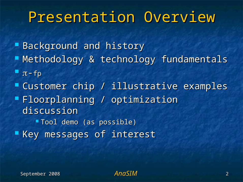
Power Integrity Challenges: Power Integrity Challenges: CPUCPU
Power doublesevery ~36 months
Transistors doubleevery ~18 months
Operating modescreate load shifts
Which createsupply voltage‘droops’
Managed by package devices
(Original figure from C. Baldwin)(Original figure from C. Baldwin)
Mother Board
Capacitors
MicroprocessorHeat Spreader
PackageSubstrate
Pentium™ is a trademark of Intel® Corporation
September 2008September 2008 AnaSIMAnaSIM 44
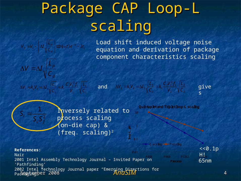
Package CAP Loop-L scalingPackage CAP Loop-L scaling
st
d
pif Iret
C
LIVV
)sin( 1
d
p
C
LIV
1
1
1
12
11
1
1111 C
L
V
fVCk
C
LIVkV iv
2
2
2
12
22
2
2222 C
L
V
fVCk
C
LIVkV iv and gives
2
1
fcl SSS
Quintuplet and Triplet loop-L scaling
0.01
0.1
1
10
P858 P860 P1262 P1264
Process
loo
p-L
, p
H
Q-scaling T-scaling
Load shift induced voltage noise equation and derivation of packagecomponent characteristics scaling
Inversely related to process scaling(on-die cap) & (freq. scaling)2
65nm
<<0.1pH! References:Nair2001 Intel Assembly Technology Journal – Invited Paper on ‘Pathfinding’2002 Intel Technology Journal paper “Emerging Directions for Packaging…”
September 2008September 2008 AnaSIMAnaSIM 55
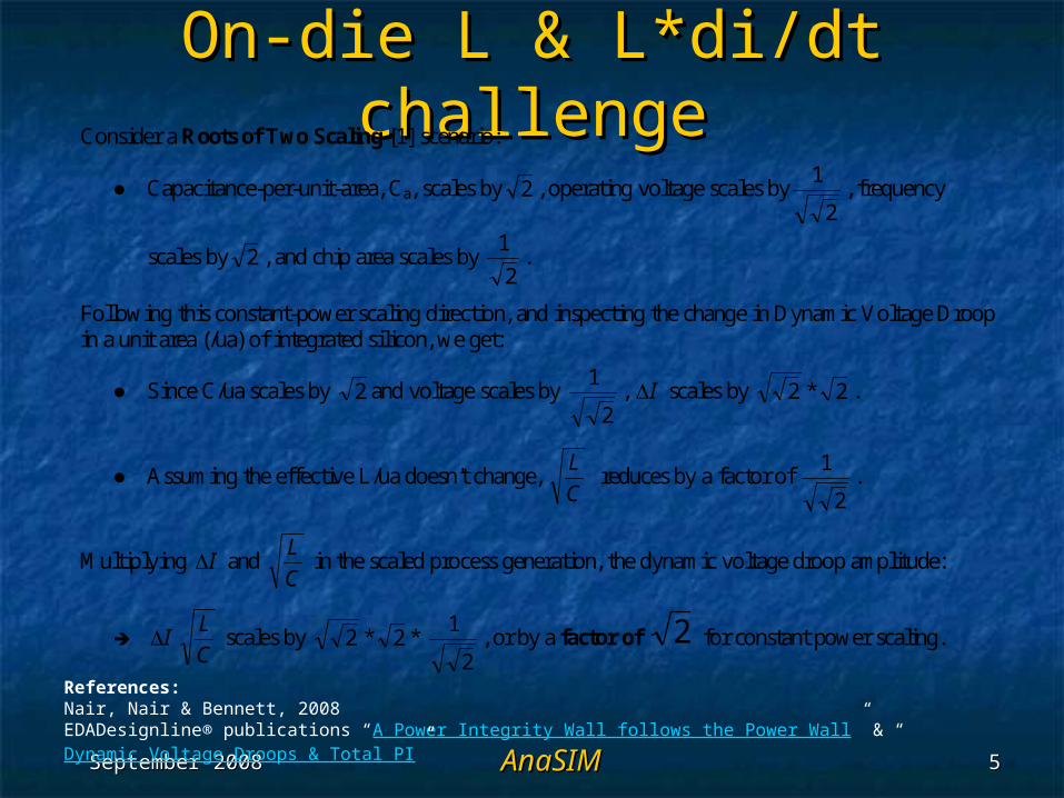
On-die L & L*di/dt challengeOn-die L & L*di/dt challengeConsider a Roots of Two Scaling [1] scenario:
Capacitance-per-unit-area, Ca, scales by 2 , operating voltage scales by2
1, frequency
scales by 2 , and chip area scales by 2
1.
Following this constant-power scaling direction, and inspecting the change in Dynamic Voltage Droop in a unit area (/ua) of integrated silicon, we get:
Since C/ua scales by 2 and voltage scales by 2
1, I scales by 2 * 2 .
Assuming the effective L/ua doesn't change, C
L reduces by a factor of
2
1.
Multiplying I and C
L in the scaled process generation, the dynamic voltage droop amplitude:
IC
L scales by 2 * 2 *
2
1, or by a factor of 2 for constant power scaling.
References:Nair, Nair & Bennett, 2008EDADesignline® publications “A Power Integrity Wall follows the Power Wall” & “Dynamic Voltage Droops & Total PI”
September 2008September 2008 AnaSIMAnaSIM 66
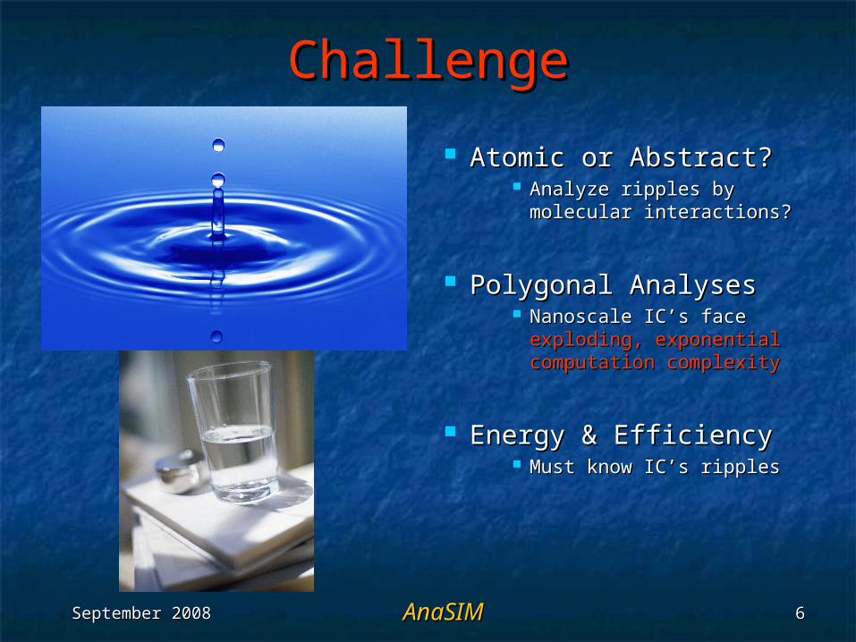
ChallengeChallenge
Atomic or Abstract? Atomic or Abstract? Analyze ripples by Analyze ripples by
molecular interactions? molecular interactions?
Polygonal AnalysesPolygonal Analyses Nanoscale IC’s face Nanoscale IC’s face
exploding, exponential exploding, exponential computation complexitycomputation complexity
Energy & EfficiencyEnergy & Efficiency Must know IC’s ripplesMust know IC’s ripples
September 2008September 2008 AnaSIMAnaSIM 77
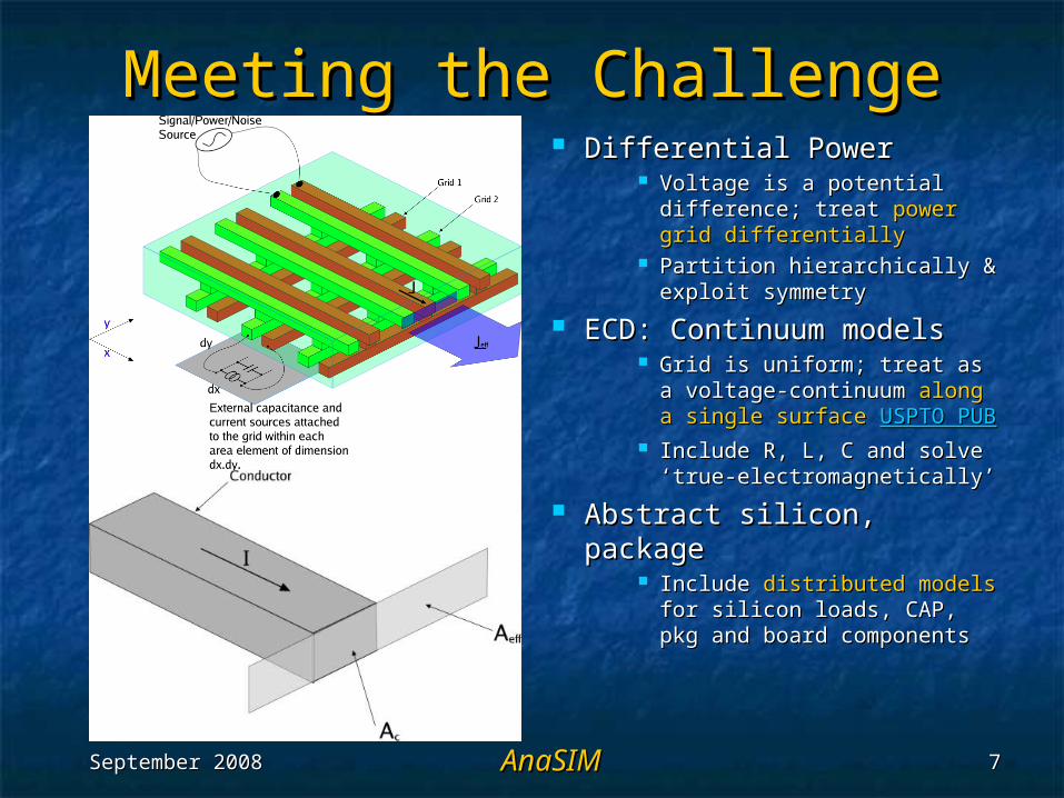
Meeting the ChallengeMeeting the Challenge Differential Power Differential Power
Voltage is a potential Voltage is a potential difference; treat difference; treat power grid power grid differentiallydifferentially
Partition hierarchically & Partition hierarchically & exploit symmetryexploit symmetry
ECD: Continuum modelsECD: Continuum models Grid is uniform; treat as a Grid is uniform; treat as a
voltage-continuum voltage-continuum along a along a single surfacesingle surface USPTO PUBUSPTO PUB
Include R, L, C and solve Include R, L, C and solve ‘true-electromagnetically’‘true-electromagnetically’
Abstract silicon, packageAbstract silicon, package Include Include distributed modelsdistributed models
for silicon loads, CAP, pkg for silicon loads, CAP, pkg and board componentsand board components
September 2008September 2008 AnaSIMAnaSIM 88
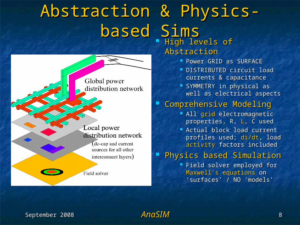
Abstraction & Physics-based Abstraction & Physics-based SimsSims
High levels of AbstractionHigh levels of Abstraction Power GRID as SURFACEPower GRID as SURFACE DISTRIBUTED circuit load DISTRIBUTED circuit load
currents & capacitancecurrents & capacitance SYMMETRY in physical as SYMMETRY in physical as
well as electrical aspects well as electrical aspects
Comprehensive ModelingComprehensive Modeling All All gridgrid electromagnetic electromagnetic
properties, R, properties, R, LL, C used, C used Actual block load current Actual block load current
profiles used; profiles used; di/dtdi/dt, load , load activityactivity factors included factors included
Physics based SimulationPhysics based Simulation Field solver employed for Field solver employed for
Maxwell’s equationsMaxwell’s equations on on ‘surfaces’ / NO ‘models’ ‘surfaces’ / NO ‘models’
September 2008September 2008 AnaSIMAnaSIM 99
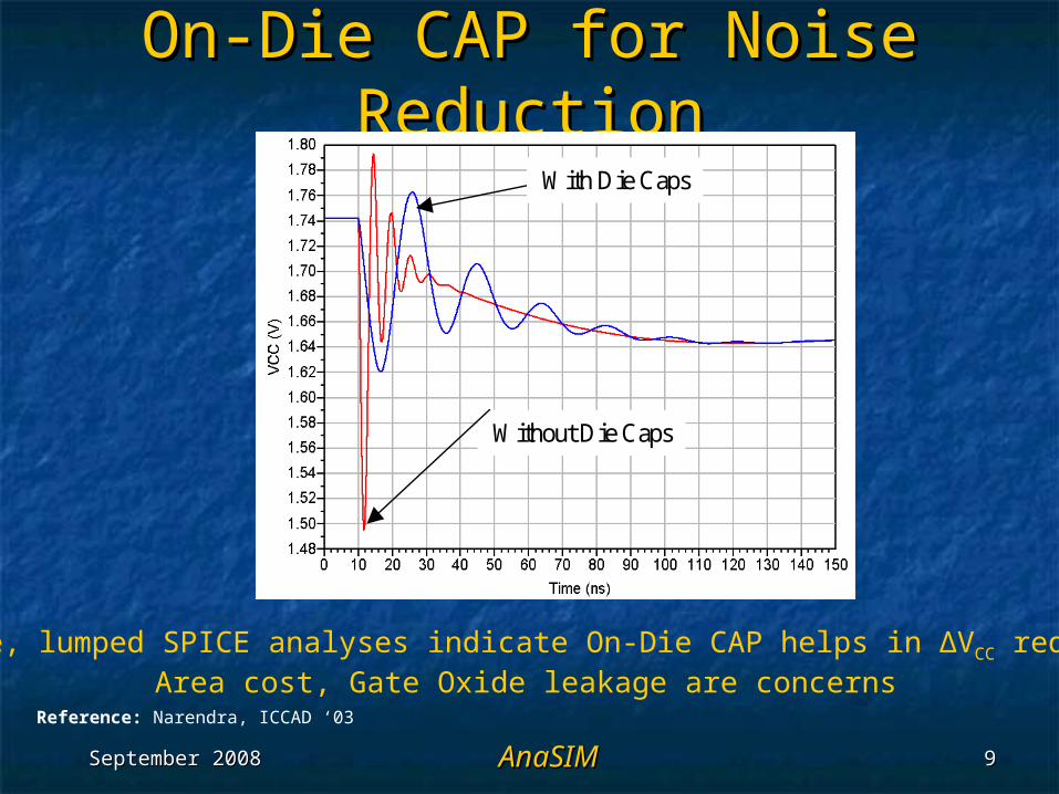
On-Die CAP for Noise On-Die CAP for Noise ReductionReduction
With Die Caps
Without Die Caps
With Die Caps
Without Die Caps
Simple, lumped SPICE analyses indicate On-Die CAP helps in ΔVCC reductionArea cost, Gate Oxide leakage are concerns
Reference: Narendra, ICCAD ‘03
September 2008September 2008 AnaSIMAnaSIM 1010
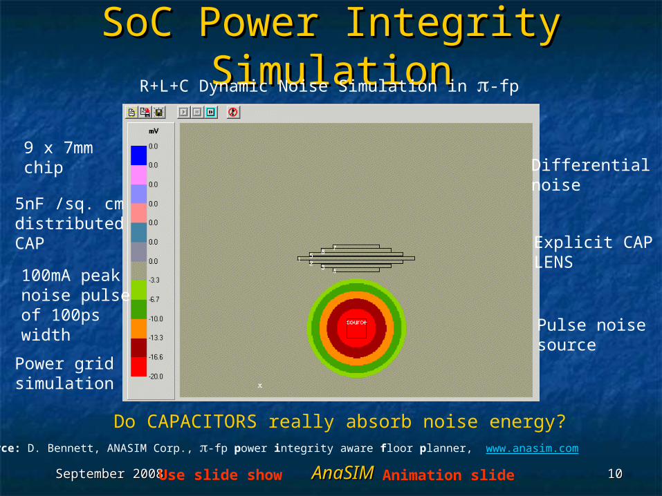
SoC Power Integrity SoC Power Integrity SimulationSimulation
Do CAPACITORS really absorb noise energy?
9 x 7mm chip
5nF /sq. cm distributedCAP
100mA peak noise pulseof 100pswidth
Power grid simulation
Explicit CAP LENS
Pulse noise source
Differential noise
R+L+C Dynamic Noise Simulation in -fp
Source: D. Bennett, ANASIM Corp., -fp power integrity aware floor planner, www.anasim.com
Animation slideUse slide show
September 2008September 2008 AnaSIMAnaSIM 1111
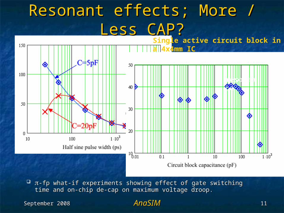
Single active circuit block in a 4x4mm IC
-fp what-if experiments showing effect of gate switching -fp what-if experiments showing effect of gate switching time and on-chip de-cap on maximum voltage droop.time and on-chip de-cap on maximum voltage droop.
resonance
Resonant effects; More / Less Resonant effects; More / Less CAP?CAP?
September 2008September 2008 AnaSIMAnaSIM 1212
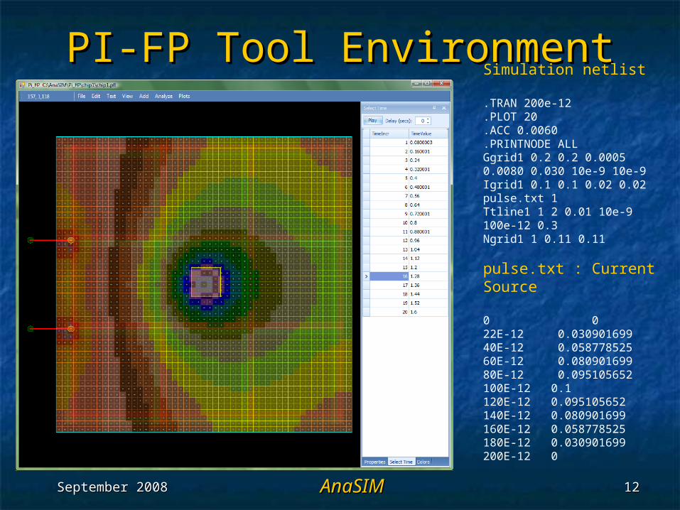
PI-FP Tool EnvironmentPI-FP Tool EnvironmentSimulation netlist
.TRAN 200e-12
.PLOT 20
.ACC 0.0060
.PRINTNODE ALLGgrid1 0.2 0.2 0.0005 0.0080 0.030 10e-9 10e-9Igrid1 0.1 0.1 0.02 0.02 pulse.txt 1Ttline1 1 2 0.01 10e-9 100e-12 0.3Ngrid1 1 0.11 0.11
pulse.txt : Current Source
0 022E-12 0.03090169940E-12 0.05877852560E-12 0.08090169980E-12 0.095105652100E-12 0.1120E-12 0.095105652140E-12 0.080901699160E-12 0.058778525180E-12 0.030901699200E-12 0
September 2008September 2008 AnaSIMAnaSIM 1313
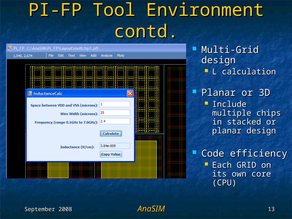
PI-FP Tool Environment PI-FP Tool Environment contd.contd.
Multi-Grid Multi-Grid designdesign L calculationL calculation
Planar or 3DPlanar or 3D Include multiple Include multiple
chips in stacked chips in stacked or planar designor planar design
Code efficiencyCode efficiency Each GRID on its Each GRID on its
own core (CPU)own core (CPU)
September 2008September 2008 AnaSIMAnaSIM 1414
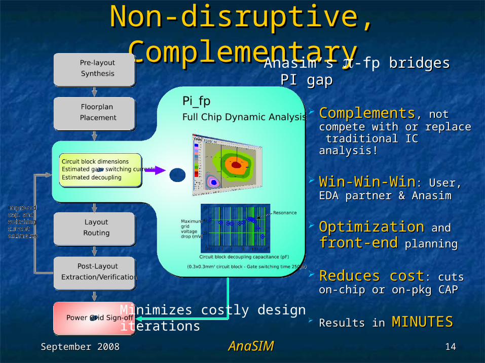
Non-disruptive, Non-disruptive, ComplementaryComplementaryAnasim’s -fp bridges PI bridges PI
gapgap
ComplementsComplements,, not not compete with or replace compete with or replace traditional IC analysis!traditional IC analysis!
Win-Win-WinWin-Win-Win: User, : User, EDA partner & AnasimEDA partner & Anasim
OptimizationOptimization and and
front-endfront-end planning planning
Reduces costReduces cost: cuts : cuts on-chip or on-pkg CAPon-chip or on-pkg CAP
Results inResults in MINUTESMINUTESMinimizes costly design iterations
September 2008September 2008 AnaSIMAnaSIM 1515
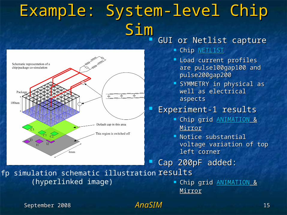
Example: System-level Chip Example: System-level Chip Sim Sim
GUI or Netlist capture GUI or Netlist capture Chip Chip NETLISTNETLIST Load current profiles are Load current profiles are
pulse100gap100 and pulse100gap100 and pulse200gap200pulse200gap200
SYMMETRY in physical as SYMMETRY in physical as well as electrical aspects well as electrical aspects
Experiment-1 resultsExperiment-1 results Chip grid Chip grid ANIMATIONANIMATION & &
MirrorMirror Notice substantial Notice substantial
voltage variation of top voltage variation of top left cornerleft corner
Cap 200pF added: Cap 200pF added: resultsresults
Chip grid Chip grid ANIMATIONANIMATION & & MirrorMirror
-fp simulation schematic illustration(hyperlinked image)
September 2008September 2008 AnaSIMAnaSIM 1616
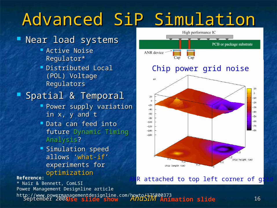
Advanced SiP SimulationAdvanced SiP Simulation Near load systemsNear load systems
Active Noise Active Noise Regulator*Regulator*
Distributed Local (POL) Distributed Local (POL) Voltage RegulatorsVoltage Regulators
Spatial & TemporalSpatial & Temporal Power supply variation Power supply variation
in x, y and tin x, y and t Data can feed into Data can feed into
future future Dynamic Timing Dynamic Timing AnalysisAnalysis??
Simulation speed Simulation speed allows ‘allows ‘what-ifwhat-if’ ’ experiments for experiments for optimizationoptimization
Chip power grid noise
ANR attached to top left corner of gridReference:* Nair & Bennett, ComLSI Power Management Designline article http://www.powermanagementdesignline.com/howto/175800373
Animation slideUse slide show
September 2008September 2008 AnaSIMAnaSIM 1717
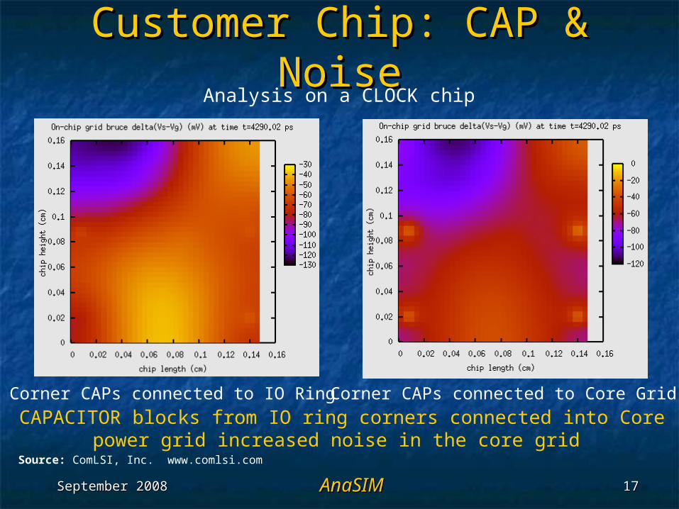
Customer Chip: CAP & NoiseCustomer Chip: CAP & Noise
CAPACITOR blocks from IO ring corners connected into Core power grid increased noise in the core grid
Corner CAPs connected to IO Ring Corner CAPs connected to Core Grid
Analysis on a CLOCK chip
Source: ComLSI, Inc. www.comlsi.com
September 2008September 2008 AnaSIMAnaSIM 1818
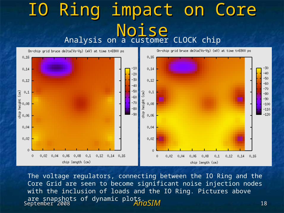
IO Ring impact on Core IO Ring impact on Core NoiseNoise
The voltage regulators, connecting between the IO Ring and the Core Grid are seen to become significant noise injection nodes with the inclusion of loads and the IO Ring. Pictures above are snapshots of dynamic plots.
Analysis on a customer CLOCK chip
September 2008September 2008 AnaSIMAnaSIM 1919
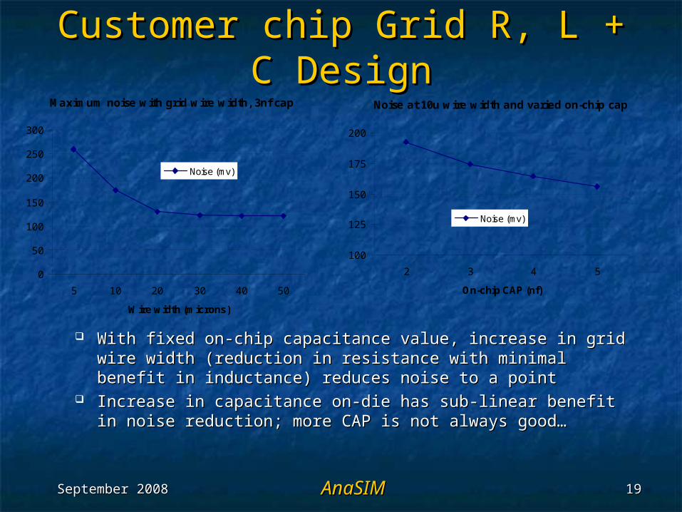
Customer chip Grid R, L + C Customer chip Grid R, L + C DesignDesign
With fixed on-chip capacitance value, increase in grid With fixed on-chip capacitance value, increase in grid wire width (reduction in resistance with minimal benefit wire width (reduction in resistance with minimal benefit in inductance) reduces noise to a pointin inductance) reduces noise to a point
Increase in capacitance on-die has sub-linear benefit in Increase in capacitance on-die has sub-linear benefit in noise reduction; more CAP is not always good…noise reduction; more CAP is not always good…
Noise at 10u wire width and varied on-chip cap
100
125
150
175
200
2 3 4 5
On-chip CAP (nf)
Noise (mv)
Maximum noise with grid wire width, 3nf cap
0
50
100
150
200
250
300
5 10 20 30 40 50
Wire width (microns)
Noise (mv)
September 2008September 2008 AnaSIMAnaSIM 2020
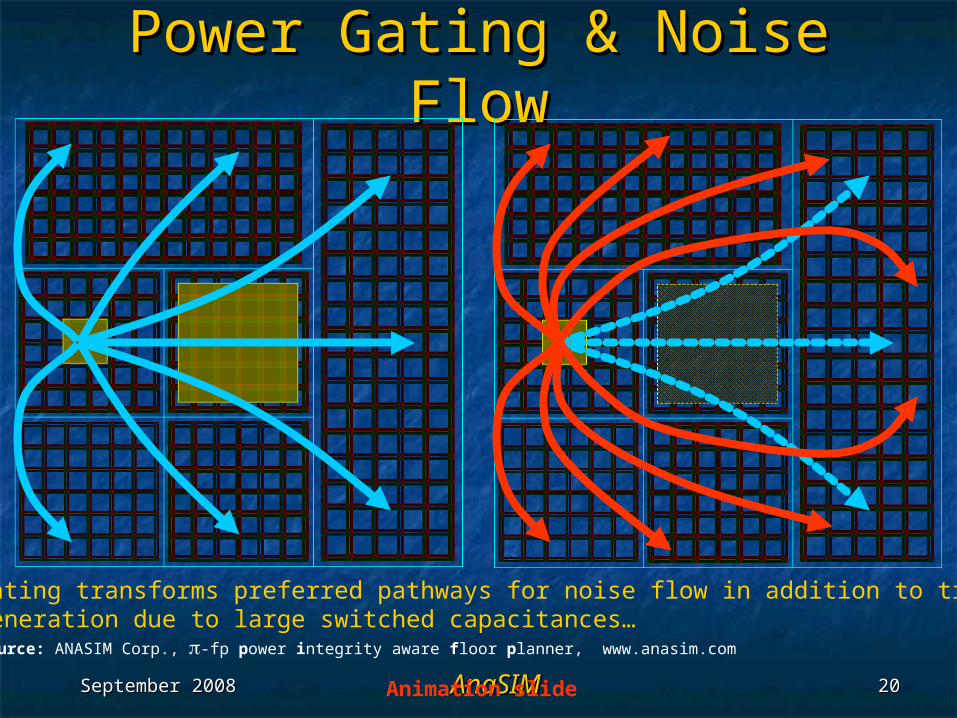
Power Gating & Noise FlowPower Gating & Noise Flow
Source: ANASIM Corp., -fp power integrity aware floor planner, www.anasim.com
Power Gating transforms preferred pathways for noise flow in addition to transientnoise generation due to large switched capacitances…
Animation slide
September 2008September 2008 AnaSIMAnaSIM 2121
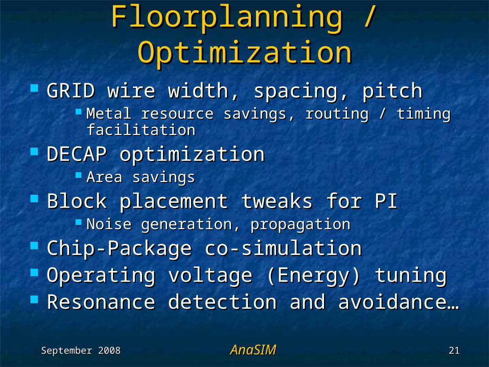
Floorplanning / OptimizationFloorplanning / Optimization
GRID wire width, spacing, pitchGRID wire width, spacing, pitch Metal resource savings, routing / timing Metal resource savings, routing / timing
facilitationfacilitation DECAP optimizationDECAP optimization
Area savingsArea savings Block placement tweaks for PIBlock placement tweaks for PI
Noise generation, propagationNoise generation, propagation Chip-Package co-simulationChip-Package co-simulation Operating voltage (Energy) tuningOperating voltage (Energy) tuning Resonance detection and avoidance…Resonance detection and avoidance…
September 2008September 2008 AnaSIMAnaSIM 2222
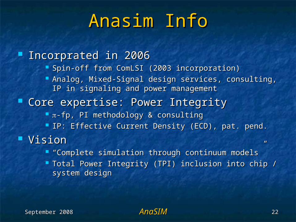
Anasim InfoAnasim Info
Incorprated in 2006Incorprated in 2006 Spin-off from ComLSI (2003 incorporation)Spin-off from ComLSI (2003 incorporation) Analog, Mixed-Signal design services, consulting, IP in Analog, Mixed-Signal design services, consulting, IP in
signaling and power managementsignaling and power management
Core expertise: Power IntegrityCore expertise: Power Integrity -fp, PI methodology & consulting -fp, PI methodology & consulting IP: Effective Current Density (ECD), pat. pend. IP: Effective Current Density (ECD), pat. pend.
VisionVision ““Complete simulation through continuum models”Complete simulation through continuum models” Total Power Integrity (TPI) inclusion into chip / system Total Power Integrity (TPI) inclusion into chip / system
designdesign
September 2008September 2008 AnaSIMAnaSIM 2323
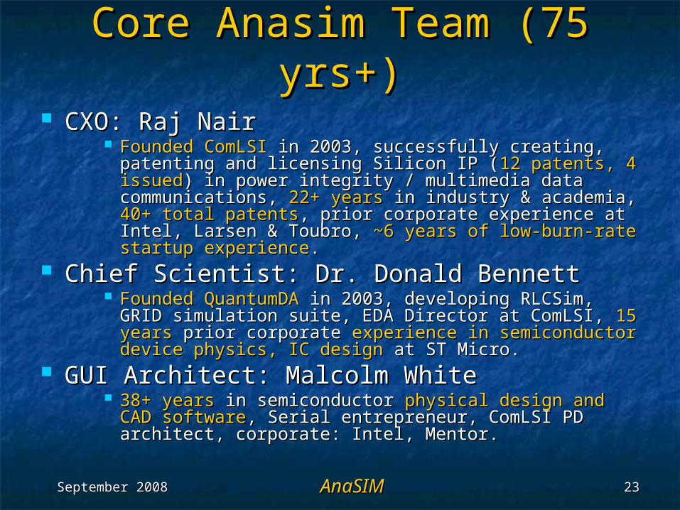
Core Anasim Team (75 Core Anasim Team (75 yrs+)yrs+)
CXO: Raj NairCXO: Raj Nair Founded ComLSIFounded ComLSI in 2003, successfully creating, in 2003, successfully creating,
patenting and licensing Silicon IP (patenting and licensing Silicon IP (12 patents, 4 12 patents, 4 issuedissued) in power integrity / multimedia data ) in power integrity / multimedia data communications, communications, 22+ years22+ years in industry & academia, in industry & academia, 40+ total patents40+ total patents, prior corporate experience at Intel, , prior corporate experience at Intel, Larsen & Toubro, Larsen & Toubro, ~6 years of low-burn-rate startup ~6 years of low-burn-rate startup experienceexperience..
Chief Scientist: Dr. Donald BennettChief Scientist: Dr. Donald Bennett Founded QuantumDAFounded QuantumDA in 2003, developing RLCSim, in 2003, developing RLCSim,
GRID simulation suite, EDA Director at ComLSI, GRID simulation suite, EDA Director at ComLSI, 15 15 yearsyears prior corporate prior corporate experience in semiconductor experience in semiconductor device physics, IC designdevice physics, IC design at ST Micro. at ST Micro.
GUI Architect: Malcolm WhiteGUI Architect: Malcolm White 38+ years38+ years in semiconductor in semiconductor physical design and CAD physical design and CAD
softwaresoftware, Serial entrepreneur, ComLSI PD architect, , Serial entrepreneur, ComLSI PD architect, corporate: Intel, Mentor. corporate: Intel, Mentor.
September 2008September 2008 AnaSIMAnaSIM 2424
Milestones to-dateMilestones to-date
Chip Floorplan ‘true-electromagnetic’ Chip Floorplan ‘true-electromagnetic’ simulationsimulation
Patent pendingPatent pending algorithm – algorithm – ECDECD Front-endFront-end chip chip floorplan optimizationfloorplan optimization now feasible. now feasible.
Stand-alone Tool released to market (2008)Stand-alone Tool released to market (2008) GUI, Simulator, Input language, Results Viewer & DEMOGUI, Simulator, Input language, Results Viewer & DEMO Close to Close to signing on a Japanese distributorsigning on a Japanese distributor
Industry Validation ongoingIndustry Validation ongoing Anasim white papers Anasim white papers top threetop three of EDA Designline’s of EDA Designline’s
highest user-ratedhighest user-rated papers; SoC2007, Nanotech 2008 papers; SoC2007, Nanotech 2008 and NanoEquity 2008 invited presentationsand NanoEquity 2008 invited presentations
Compiling a book Compiling a book onon Power Integrity (PI), Power Integrity (PI), Prentice Hall™Prentice Hall™
September 2008September 2008 AnaSIMAnaSIM 2525
SummarySummary Anasim bringing sea change into SoC Anasim bringing sea change into SoC
methodology with methodology with physics-based analyses andphysics-based analyses and high levels of abstractionhigh levels of abstraction
Benefits to chip resource usage, area, energy, Benefits to chip resource usage, area, energy, performance, and total design effortperformance, and total design effort
Non-disruptive, Non-disruptive, Win-Win-WinWin-Win-Win engagement engagement Fills the GAPFills the GAP in Total Power Integrity analyses in Total Power Integrity analyses Links, tel. Links, tel. [email protected]@anasim.com +1 480-694-5984 +1 480-694-5984
AnasimAnasim White Papers White Papers pifp1.pdfpifp1.pdf, , pifp2.pdfpifp2.pdf, , pifp3.pdfpifp3.pdf Product - Product - -fp brochure-fp brochure ComLSI, ComLSI, parent coparent co..