Embed Size (px)
Citation preview
International Journal of Current Engineering and Technology E-ISSN 2277 – 4106, P-ISSN 2347 – 5161 ©2015INPRESSCO®, All Rights Reserved Available at http://inpressco.com/category/ijcet
Research Article
2492| International Journal of Current Engineering and Technology, Vol.5, No.4 (Aug 2015)
Analyzing Thermal Insulation for Effective Hydrate Prevention in Conceptual Subsea Pipeline Design
Okologume Wilfred†* and Dulu Appah†
†Department of Petroleum and Gas Engineering, University of Port Harcourt, Port Harcourt, Nigeria.
Accepted 10 July 2015, Available online 16 July 2015, Vol.5, No.4 (Aug 2015)
Abstract Produced natural gas stream from the reservoir is always saturated with water and one of the problems associated with its transmission especially in subsea pipeline is the formation of hydrates. Hydrate formation in subsea pipelines is a major problem that arises due to temperature drop and other thermodynamic changes during production. The formation of hydrates in subsea pipelines should be prevented effectively to guarantee that the pipeline operates normally. Insulating subsea pipelines is essential to avoid possible hydrate formation. This study focused on discussion and analysis on both theoretical correlations and published experimental data which evaluates conditions that favours hydrate formation in subsea pipeline. It presents an overview of hydrate prevention and control measures based on existing hydrate predictive and inhibition methods. A field with slightly modified natural gas compositions was studied and the hydrate formation temperature at the pipeline phase was predicted using simulation software. Heat transfer equation under steady state fluid flow as well as that for rate of heat loss was used to develop a simple FLOWLINE software model; to analyze the insulation material required to effectively prevent hydrate formation in a subsea pipeline. The predicted hydrate formation data generated was incorporated into a case study field’s pipeline design base parameters. The analysed result was applied to a pipeline and facility design case study of an offshore petroleum production system using the PIPESIM simulator software. The aim of comparing the efficacy of the selected insulation material thickness needed to prevent hydrate formation in the pipeline was achieved. The tools applied here are relatively easy to study sensitivities and analyse conceptual subsea pipeline design calculations leading up to selection of thermal insulation for effective hydrate prevention as part of a deep-water project development. Keywords: Hydrate, Flow Assurance, FLOWLINE, Simulator, Thermal Insulation and Thermal Analysis. 1. Introduction
1 The oil industry is today forced into less accessible areas to acquire more oil to satisfy a growing energy market. Due to the increasing demand for petroleum products by the world’s ever increasing population, most especially in the third world countries, the focal point of oil and gas exploration and production has advanced from continental shelves (e.g. the North Sea) to deep water (e.g. Niger Delta and Gulf of Mexico) where drilling operations have been successfully accomplished in over 10,000ft of water. The subsea environment which involves low temperatures as well as high pressures, high water cuts and longer transfer times provide conditions that are ideal for hydrates and wax formation, and other solids deposits (Akpabio, 2013). These are the fundamental impediments to production of oil and gas through long distance subsea pipelines, especially at shut-down and restart situations. Though the existing subsea processing and
*Corresponding author: Okologume Wilfred
transportation facilities enable this exploitation, but adequate flow assurance is needed. Flow assurance is a phenomenon which ensures the successful and economical flow of hydrocarbon stream from the reservoir to the point of sale (Osokogwu et.al, 2014).
Subsea pipelines represent at least 25% of the total project cost and it’s one of the reasons for the flow assurance studies. In deepwater oil exploration wells are located far from platforms, and crude oil often has to be transported over long distances in subsea pipelines (Phil, 2007). The oil is cooled on its way to the destination due to heat transfer, through the pipelines walls, with the surrounding sea water. Temperature related transportation problems can take place because if the pipelines is not insulated the temperature will drop quickly. This may lead to the precipitation of asphaltenes and/or paraffin wax and the formation of hydrates (Boyun et.al, 2007). These flow assurance problems can result in lost production and blocking of the pipelines.
Thus, during detail engineering of subsea pipeline, it becomes mandatory to have proper insulation type
Okologume Wilfred et al Analyzing Thermal Insulation for Effective Hydrate Prevention in Conceptual Subsea Pipeline Design
2493| International Journal of Current Engineering and Technology, Vol.5, No.4 (Aug 2015)
and insulation thickness selection done at the early stages of project, so as to assure the proper flow of the fluids in the pipeline, at desired operating conditions. 2. Thermal Prevention of Hydrate As pipeline stoppage during winter were at one time, commonly suppose to be cause by the freezing of water, one of the ealiest method used to remove such stoppage was to apply heat to the line. Although effective in certain instanse, open fire in the vincinity of the pipeline carrying natural gas are a fire hazard that should be avoided. This method require the pipeline to be fired by burning combustible materials in such close contact with the pipe. But if care is not taken , the pipe may be overheated and rapture, such a break in pipeline may result in a serious fire (Zarinabadi et.al, 2011). This method can only be effective if the position of the blockage due to hydrate can be determined exactly.
Steady state temperature profile from the produced fluid can be used to identify the flow rates and insulation preference that can keep the system above the critical minimum temperature during production. Thermal analysis of a typical subsea production system, which predicts the temperature profile along the flowline, is one of the most important steps in the subsea layout design. The pipeline is exposed to the cooling sea current, thus the gas inside the pipeline is cooled down to temperatures that favours hydrate formation (Akpabio, 2012). However, heat transfer analysis of the pipeline systems is of great importance for the prediction and prevention of hydrate formations (Boyun et.al, 2007).
Assuming the cold seawater has a constant temperature, the resultant governing equations to the heat transfer problem in subsea pipelines under steady state fluid flow condition from Boyun, et. al. (2007) is summarized herein;
[ ] (1)
Also, the rate of heat transfer over the whole length of the pipeline across the insulation layer is expressed as;
(
⟨{ }
[ ]⟩) (2)
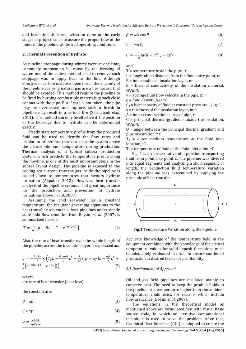
where, q = rate of heat transfer (heat loss) the constant are; B = αβ (3) C = αγ (4)
(5)
(6) (7)
(8)
and T = temperature inside the pipe, oC L = longitudinal distance from the fluid entry point, m R = inner radius of insulation layer, m k = thermal conductivity of the insulation material, W/moC v = average fluid flow velocity in the pipe, m-s ρ = fluid density, kg/m3 Cp = heat capacity of fluid at constant pressure, J/kgoC s = thickness of the insulation layer, mm A = inner cross-sectional area of pipe, m G = principal thermal-gradient outside the insulation, W/moC Ɵ = angle between the principal thermal gradient and pipe orientation, o Ɵ To = outer medium temperature at the fluid inlet location, oC Ts = temperature of fluid at the fluid inlet point, oC
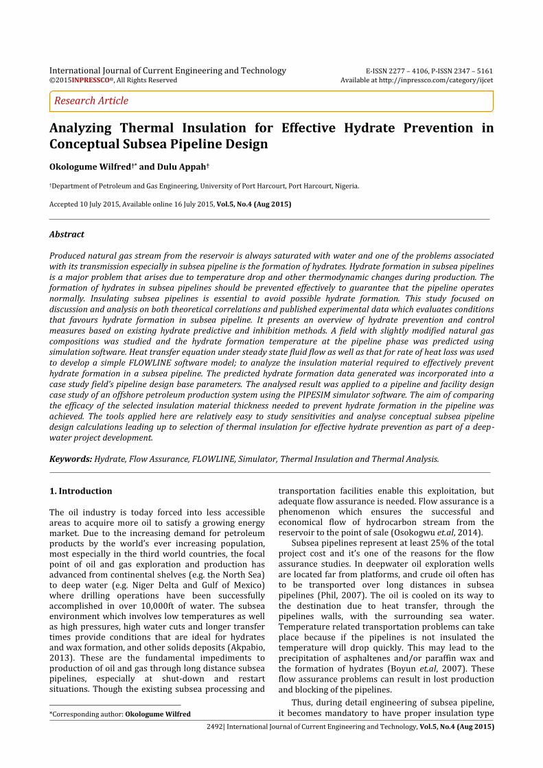
Fig. 1 is a representative of a pipeline transporting fluid from point 1 to point 2. The pipeline was divided into equal segments and analyzing a short segment of length, the production fluid temperature variation along the pipeline was determined by applying the principle of heat transfer.
Fig.1 Temperature Variation along the Pipeline Accurate knowledge of the temperature field in the equipment combined with the knowledge of the critical temperature values for solid deposit formations must be adequately evaluated in order to ensure continued production at desired levels for profitability.
2.1 Development of Approach
Oil and gas field pipelines are insulated mainly to conserve heat. The need to keep the product fluids in the pipeline at a temperature higher than the ambient temperature could exist, for reasons which include flow assurance (Boyun et.al, 2007).
The equations in the theoretical model as mentioned above are formulated first with Visual Basic source code, in which an iterative computational technique is used to solve the problem. After that, Graphical User Interface (GUI) is adopted to create the
Okologume Wilfred et al Analyzing Thermal Insulation for Effective Hydrate Prevention in Conceptual Subsea Pipeline Design
2494| International Journal of Current Engineering and Technology, Vol.5, No.4 (Aug 2015)
user-friendly interface. Furthermore, the testing and debugging of the module are conducted backstage. Finally, the software (FLOWLINE) is published as an executable file that can be used in normal computers, even without Visual Basic installed. Appendices A and B shows the main user interface of the software, for both heat transfer and heat loss calculations. The clear and concise user interface enable user to operate the software easily to analyse the temperature profile in a steady-state fluid flow production conditions along the pipeline and the quantity of insulation material that can be used to prevent hydrates formation in subsea pipeline with given operating temperature profile. 2.2 Case Study Definition A recently discovered oil and gas field was developed via a single wellhead. A subsea pipeline was designed to transport natural gas from a satellite platform to a processing facility. The necessary flow assurance analysis needed to determine the minimum insulation requirement was performed. These analyses include the following:
1) Flash analysis of the production fluid which determined the hydrate formation temperature in the range of operating pressure.
2) Heat transfer analysis which determined the type and thickness of insulation required for the pipeline.
3) Case study in flow assurance was performed with PIPESIM simulator considering an offshore operating system.
In preventing hydrate formation using insulation,
hydrate depression point was first determined for the
composition of the fluid as given in table 1. The given
calculations were performed in the FLOWLINE
software to select the insulation material and
appropriate insulation layer thickness using a design
base for a pipeline insulation presented in table 2. The
criterion for the design was to ensure that the
temperature at any point in the pipeline will not drop
to less than 26oC, as required by flow assurance. With
the analysed insulation material, the required
thickness of insulation (Polyurethane) at the pipeline
to prevent hydrate formation and blockage of pipeline
during transmission was estimated.
The pipeline heat losses for different insulation
materials and thickness was further analysed using the
FLOWLINE software. In choosing the optimum
solution, we compared with an unrealistic insulation
thickness with a reasonable insulation thickness that
prevented hydrate formation in the pipeline. With this
comparison, it was possible to evaluate which were the
minimum heat losses. The modeled system data for
Risers 1 and 2 are presented in table 3, while field’s
boundary conditions are as presented in table 4.
Table 1 Natural Gas Compositional (Source: Anonymous)
Gas Composition Mole Fraction
N2 0.16
CO2 1.02
H2O 0.39
C1 75.42
C2 7.65
C3 4.27
n-C4 8.42
n-C5 2.67
Table 2 Base Data for Pipeline Insulation Design
(Source: Anonymous)
Parameters Description Units
Horizontal length of pipeline, L
8,000 m
Inner diameter of pipe, ID 0.2032 m
Wall thickness, WT 0.00635 m
Fluid density, ρ 881 kg/m3
Fluid specific heat capacity, Cp 2012 J/kg.oC
Average external temperature, To
10 oC
Fluid temperature at entry point, Ts
28 oC
Pipeline Inner Temperature, T 26 oC
Fluid flow rate, Q 8,605,440 m3/day
Insulation Radius R 0.1016 m
Roughness 0.001 ’’
Inner cross sectional area of pipe, A
0.032429 m2
Average fluid velocity, v 3.228304 m/s
Pipeline Orientation Angle, Ɵ 0
Insulation thermal gradient, G 0.001875 oC/m
Table 3 Data for Risers 1 and 2 (Source: Anonymous)
Parameters Description Units
Horizontal distance 0
Riser 1 elevation difference
-121.92 m
Riser 2 elevation difference
121.92 m
Inner diameter 0.2032 m
Wall thickness 0.00635 m
Roughness 0.001 ’’
Average external temperature
10 oC
Heat transfer coefficient 2012 J/kgoC
Okologume Wilfred et al Analyzing Thermal Insulation for Effective Hydrate Prevention in Conceptual Subsea Pipeline Design
2495| International Journal of Current Engineering and Technology, Vol.5, No.4 (Aug 2015)
Table 4 Boundary Conditions
Parameters Description Units
Fluid inlet pressure at satellite platform
1,800 psia
Fluid inlet temperature at satellite platform
28 oC
Minimum arrival temperature at processing facility
26 oC
Minimum arrival pressure at processing facility
1,200 psia
Design fluid flow rate 8,605,440 m3/d
Maximum turndown 4,302,720 m3/d
2.3 Modeling with PIPESIM Define Based on the available data presented, the pipeline-riser system was modeled by defining the parameters in table 4.
The pipeline wall was defined by a steel thickness of
0.00635m and the insulation material is polyurethane
of 0.0381mm as estimated by the FLOWLINE software.
The physical system was modeled firstly by adding
a source to the model. Subsequently, data relevant to
the source was added which includes the inlet pressure
of 1800psia and fluid temperature at entry point of
28oC. Secondly, a boundary node to represent the
arrival point at the processing facility was added.
Furthermore, nodes to represent each end of the
pipeline were also added to the model. The geometry
of the system was determined such that the
discretization of the pipes was done based on linear
pieces, which were separated in sections. The pipeline
and risers data were entered.
3. Results
Fig.1 Hydrocarbon Phase Envelope Showing Hydrate Formation Line
Fig. 2 FLOWLINE Software Input Interface for Steady-Flow Condition
Okologume Wilfred et al Analyzing Thermal Insulation for Effective Hydrate Prevention in Conceptual Subsea Pipeline Design
2496| International Journal of Current Engineering and Technology, Vol.5, No.4 (Aug 2015)
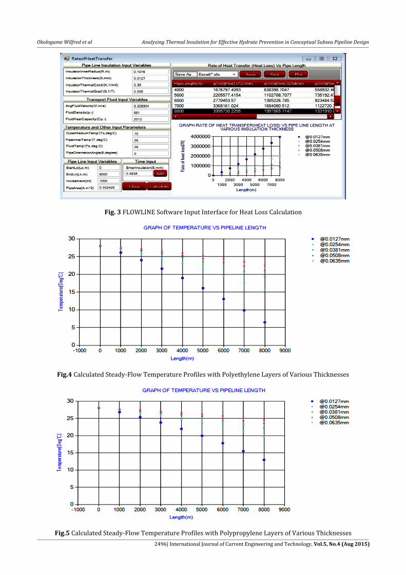
Fig. 3 FLOWLINE Software Input Interface for Heat Loss Calculation
Fig.4 Calculated Steady-Flow Temperature Profiles with Polyethylene Layers of Various Thicknesses
Fig.5 Calculated Steady-Flow Temperature Profiles with Polypropylene Layers of Various Thicknesses
Okologume Wilfred et al Analyzing Thermal Insulation for Effective Hydrate Prevention in Conceptual Subsea Pipeline Design
2497| International Journal of Current Engineering and Technology, Vol.5, No.4 (Aug 2015)
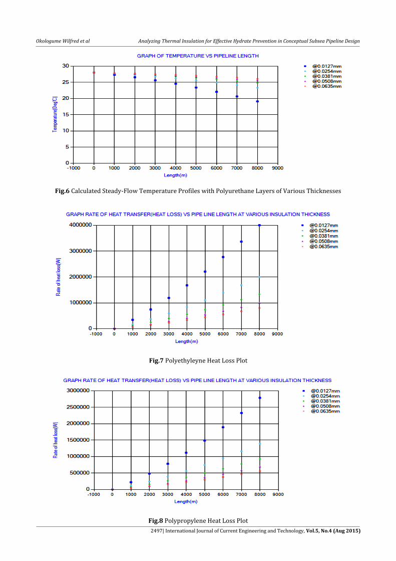
Fig.6 Calculated Steady-Flow Temperature Profiles with Polyurethane Layers of Various Thicknesses
Fig.7 Polyethyleyne Heat Loss Plot
Fig.8 Polypropylene Heat Loss Plot
Okologume Wilfred et al Analyzing Thermal Insulation for Effective Hydrate Prevention in Conceptual Subsea Pipeline Design
2498| International Journal of Current Engineering and Technology, Vol.5, No.4 (Aug 2015)
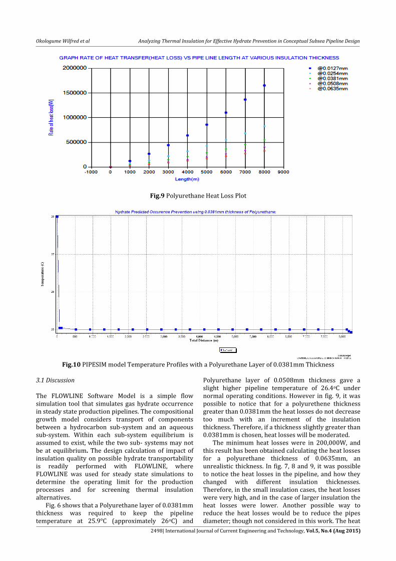
Fig.9 Polyurethane Heat Loss Plot
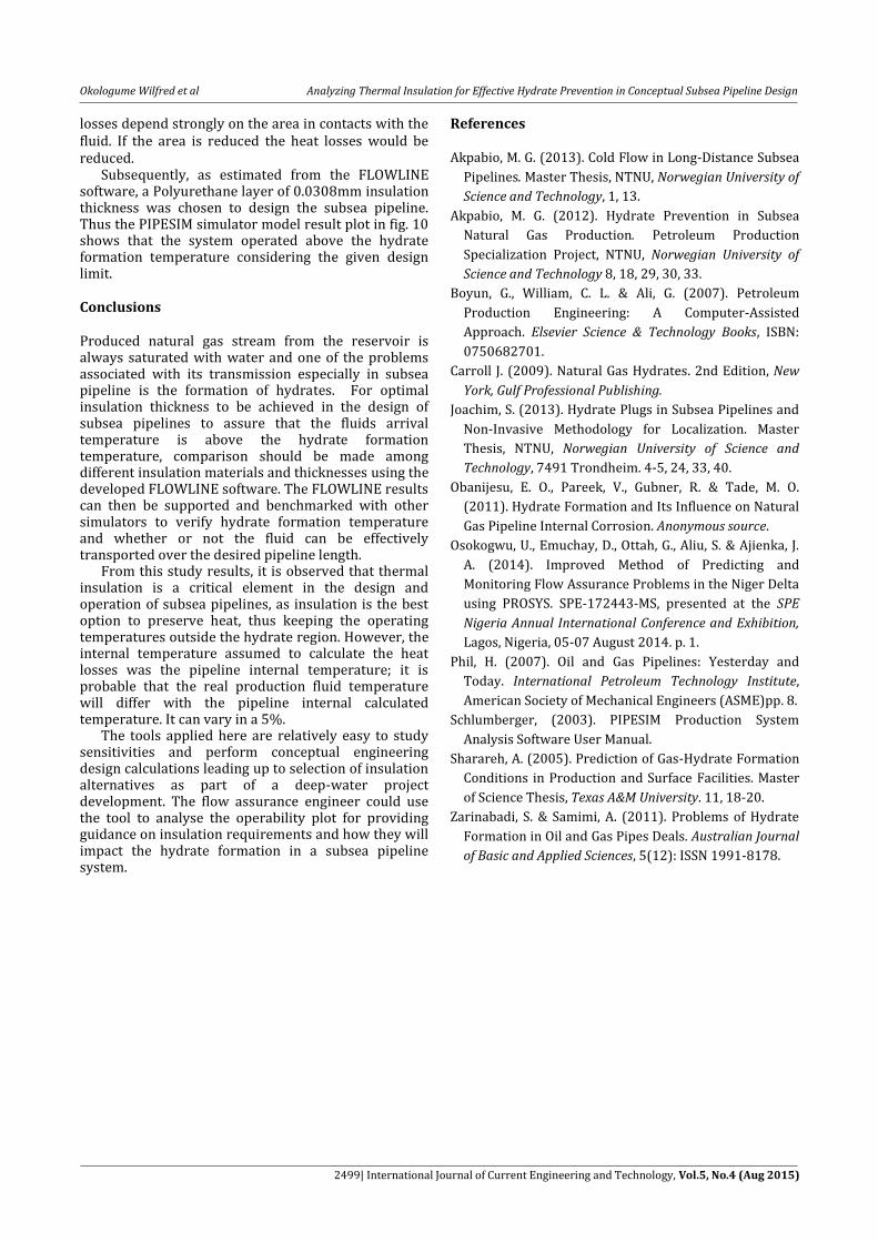
Fig.10 PIPESIM model Temperature Profiles with a Polyurethane Layer of 0.0381mm Thickness
3.1 Discussion The FLOWLINE Software Model is a simple flow simulation tool that simulates gas hydrate occurrence in steady state production pipelines. The compositional growth model considers transport of components between a hydrocarbon sub-system and an aqueous sub-system. Within each sub-system equilibrium is assumed to exist, while the two sub- systems may not be at equilibrium. The design calculation of impact of insulation quality on possible hydrate transportability is readily performed with FLOWLINE, where FLOWLINE was used for steady state simulations to determine the operating limit for the production processes and for screening thermal insulation alternatives.
Fig. 6 shows that a Polyurethane layer of 0.0381mm thickness was required to keep the pipeline temperature at 25.9°C (approximately 26oC) and
Polyurethane layer of 0.0508mm thickness gave a slight higher pipeline temperature of 26.4oC under normal operating conditions. However in fig. 9, it was possible to notice that for a polyurethene thickness greater than 0.0381mm the heat losses do not decrease too much with an increment of the insulation thickness. Therefore, if a thickness slightly greater than 0.0381mm is chosen, heat losses will be moderated.
The minimum heat losses were in 200,000W, and this result has been obtained calculating the heat losses for a polyurethane thickness of 0.0635mm, an unrealistic thickness. In fig. 7, 8 and 9, it was possible to notice the heat losses in the pipeline, and how they changed with different insulation thicknesses. Therefore, in the small insulation cases, the heat losses were very high, and in the case of larger insulation the heat losses were lower. Another possible way to reduce the heat losses would be to reduce the pipes diameter; though not considered in this work. The heat
Okologume Wilfred et al Analyzing Thermal Insulation for Effective Hydrate Prevention in Conceptual Subsea Pipeline Design
2499| International Journal of Current Engineering and Technology, Vol.5, No.4 (Aug 2015)
losses depend strongly on the area in contacts with the fluid. If the area is reduced the heat losses would be reduced.
Subsequently, as estimated from the FLOWLINE software, a Polyurethane layer of 0.0308mm insulation thickness was chosen to design the subsea pipeline. Thus the PIPESIM simulator model result plot in fig. 10 shows that the system operated above the hydrate formation temperature considering the given design limit. Conclusions Produced natural gas stream from the reservoir is always saturated with water and one of the problems associated with its transmission especially in subsea pipeline is the formation of hydrates. For optimal insulation thickness to be achieved in the design of subsea pipelines to assure that the fluids arrival temperature is above the hydrate formation temperature, comparison should be made among different insulation materials and thicknesses using the developed FLOWLINE software. The FLOWLINE results can then be supported and benchmarked with other simulators to verify hydrate formation temperature and whether or not the fluid can be effectively transported over the desired pipeline length.
From this study results, it is observed that thermal insulation is a critical element in the design and operation of subsea pipelines, as insulation is the best option to preserve heat, thus keeping the operating temperatures outside the hydrate region. However, the internal temperature assumed to calculate the heat losses was the pipeline internal temperature; it is probable that the real production fluid temperature will differ with the pipeline internal calculated temperature. It can vary in a 5%.
The tools applied here are relatively easy to study sensitivities and perform conceptual engineering design calculations leading up to selection of insulation alternatives as part of a deep-water project development. The flow assurance engineer could use the tool to analyse the operability plot for providing guidance on insulation requirements and how they will impact the hydrate formation in a subsea pipeline system.
References Akpabio, M. G. (2013). Cold Flow in Long-Distance Subsea
Pipelines. Master Thesis, NTNU, Norwegian University of
Science and Technology, 1, 13.
Akpabio, M. G. (2012). Hydrate Prevention in Subsea
Natural Gas Production. Petroleum Production
Specialization Project, NTNU, Norwegian University of
Science and Technology 8, 18, 29, 30, 33.
Boyun, G., William, C. L. & Ali, G. (2007). Petroleum
Production Engineering: A Computer-Assisted
Approach. Elsevier Science & Technology Books, ISBN:
0750682701.
Carroll J. (2009). Natural Gas Hydrates. 2nd Edition, New
York, Gulf Professional Publishing.
Joachim, S. (2013). Hydrate Plugs in Subsea Pipelines and
Non-Invasive Methodology for Localization. Master
Thesis, NTNU, Norwegian University of Science and
Technology, 7491 Trondheim. 4-5, 24, 33, 40.
Obanijesu, E. O., Pareek, V., Gubner, R. & Tade, M. O.
(2011). Hydrate Formation and Its Influence on Natural
Gas Pipeline Internal Corrosion. Anonymous source.
Osokogwu, U., Emuchay, D., Ottah, G., Aliu, S. & Ajienka, J.
A. (2014). Improved Method of Predicting and
Monitoring Flow Assurance Problems in the Niger Delta
using PROSYS. SPE-172443-MS, presented at the SPE
Nigeria Annual International Conference and Exhibition,
Lagos, Nigeria, 05-07 August 2014. p. 1.
Phil, H. (2007). Oil and Gas Pipelines: Yesterday and
Today. International Petroleum Technology Institute,
American Society of Mechanical Engineers (ASME)pp. 8.
Schlumberger, (2003). PIPESIM Production System
Analysis Software User Manual.
Sharareh, A. (2005). Prediction of Gas-Hydrate Formation
Conditions in Production and Surface Facilities. Master
of Science Thesis, Texas A&M University. 11, 18-20.
Zarinabadi, S. & Samimi, A. (2011). Problems of Hydrate
Formation in Oil and Gas Pipes Deals. Australian Journal
of Basic and Applied Sciences, 5(12): ISSN 1991-8178.