Embed Size (px)
Citation preview
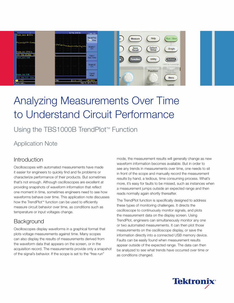
IntroductionOscilloscopes with automated measurements have made it easier for engineers to quickly find and fix problems or characterize performance of their products. But sometimes that’s not enough. Although oscilloscopes are excellent at providing snapshots of waveform information that reflect one moment in time, sometimes engineers need to see how waveforms behave over time. This application note discusses how the TrendPlot™ function can be used to efficiently measure circuit behavior over time, as conditions such as temperature or input voltages change.
Background Oscilloscopes display waveforms in a graphical format that plots voltage measurements against time. Many scopes can also display the results of measurements derived from the waveform data that appears on the screen, or in the acquisition record. The measurements provide only a snapshot of the signal’s behavior. If the scope is set to the “free run”
mode, the measurement results will generally change as new waveform information becomes available. But in order to see any trends in measurements over time, one needs to sit in front of the scope and manually record the measurement results by hand, a tedious, time consuming process. What’s more, it’s easy for faults to be missed, such as instances when a measurement jumps outside an expected range and then reads normally again shortly thereafter.
The TrendPlot function is specifically designed to address these types of monitoring challenges. It directs the oscilloscope to continuously monitor signals, and plots the measurement data on the display screen. Using TrendPlot, engineers can simultaneously monitor any one or two automated measurements. It can then plot those measurements on the oscilloscope display, or save the information directly into a connected USB memory device. Faults can be easily found when measurement results appear outside of the expected range. The data can then be analyzed to see what trends have occurred over time or as conditions changed.
Analyzing Measurements Over Timeto Understand Circuit Performance Using the TBS1000B TrendPlotTM Function
Application Note
Application Note
www.tektronix.com/tbs1000b2
With the TrendPlot measurement vs. time feature added to the toolset, your oscilloscope becomes an even more powerful tool to use for design validation.
Using TrendPlot for design validation:
Monitor power supply stability over time
Verify circuit design specifications
Capture intermittent events, and troubleshoot random shut-downs
Plot critical parameters per test point during climate testing temperature cycles
Perform temperature controlled crystal oscillator circuit tests
Application Examples Let’s say that you need to debug a power controller ramp-up failure, and you plan to use 4-corner testing (testing at the four combinations given by max-min values of temperature and input voltage). Under certain conditions, the power controller output ramp-up time exceeds the system requirements, causing a system power-on failure. You want to know the temperature and input voltage conditions that cause the failure to occur.
To determine this, you can use the TrendPlot function to monitor the signal rise time during the ramp-up period.
Begin by attaching a TPP0101 passive probe to the output of the DUT’s power module (the DUT is in ae temperature chamber) and connect the probe’s BNC to CH1 of the TBS1102B oscilloscope. On the oscilloscope follow the steps below to enable the TrendPlot function:
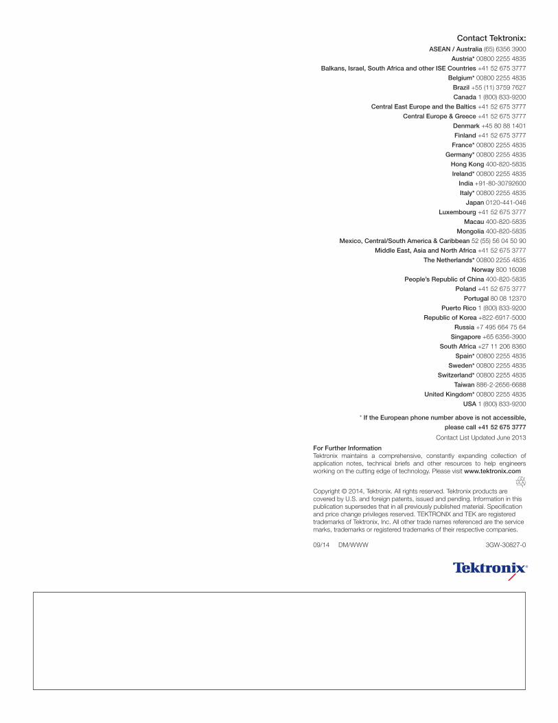
1. Power on the oscilloscope, press “default setup” and “Autoset”, and then select “ ” in the autoset menu. Adjust the settings for vertical scale and position, horizontal scale and position, and trigger level and position so that the rising portion of the signal fills the screen.
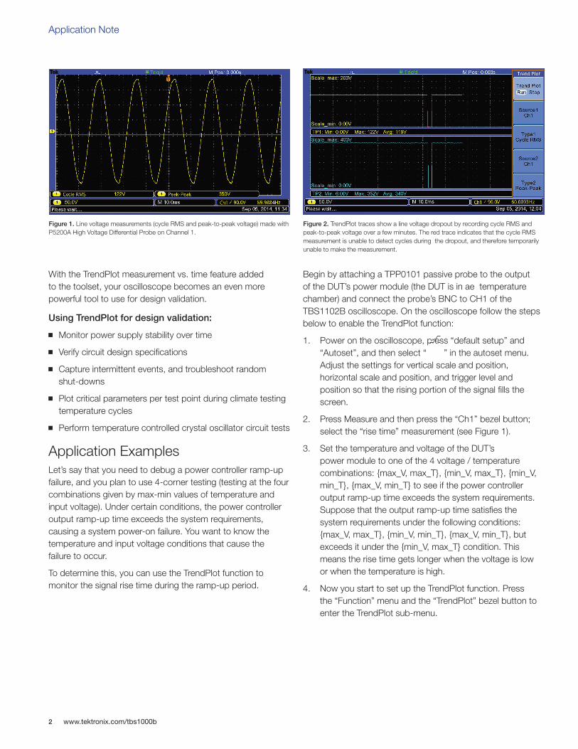
2. Press Measure and then press the “Ch1” bezel button; select the “rise time” measurement (see Figure 1).
3. Set the temperature and voltage of the DUT’s power module to one of the 4 voltage / temperature combinations: {max_V, max_T}, {min_V, max_T}, {min_V, min_T}, {max_V, min_T} to see if the power controller output ramp-up time exceeds the system requirements. Suppose that the output ramp-up time satisfies the system requirements under the following conditions: {max_V, max_T}, {min_V, min_T}, {max_V, min_T}, but exceeds it under the {min_V, max_T} condition. This means the rise time gets longer when the voltage is low or when the temperature is high.
4. Now you start to set up the TrendPlot function. Press the “Function” menu and the “TrendPlot” bezel button to enter the TrendPlot sub-menu.
Figure 1. Line voltage measurements (cycle RMS and peak-to-peak voltage) made with P5200A High Voltage Differential Probe on Channel 1.
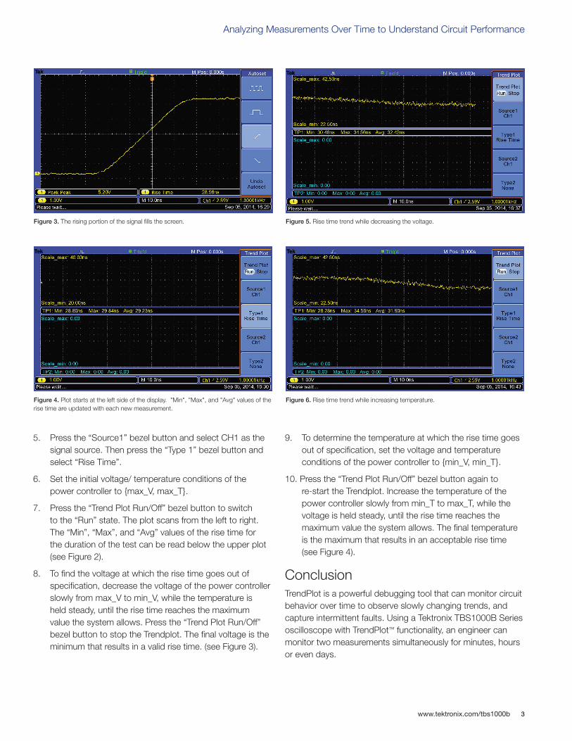
Figure 2. TrendPlot traces show a line voltage dropout by recording cycle RMS and peak-to-peak voltage over a few minutes. The red trace indicates that the cycle RMS measurement is unable to detect cycles during the dropout, and therefore temporarily unable to make the measurement.
www.tektronix.com/tbs1000b 3
Analyzing Measurements Over Time to Understand Circuit Performance
5. Press the “Source1” bezel button and select CH1 as the signal source. Then press the “Type 1” bezel button and select “Rise Time”.
6. Set the initial voltage/ temperature conditions of the power controller to {max_V, max_T}.
7. Press the “Trend Plot Run/Off” bezel button to switch to the “Run” state. The plot scans from the left to right. The “Min”, “Max”, and “Avg” values of the rise time for the duration of the test can be read below the upper plot (see Figure 2).
8. To find the voltage at which the rise time goes out of specification, decrease the voltage of the power controller slowly from max_V to min_V, while the temperature is held steady, until the rise time reaches the maximum value the system allows. Press the “Trend Plot Run/Off” bezel button to stop the Trendplot. The final voltage is the minimum that results in a valid rise time. (see Figure 3).
9. To determine the temperature at which the rise time goes out of specification, set the voltage and temperature conditions of the power controller to {min_V, min_T}.
10. Press the “Trend Plot Run/Off” bezel button again to re-start the Trendplot. Increase the temperature of the power controller slowly from min_T to max_T, while the voltage is held steady, until the rise time reaches the maximum value the system allows. The final temperature is the maximum that results in an acceptable rise time (see Figure 4).
Conclusion TrendPlot is a powerful debugging tool that can monitor circuit behavior over time to observe slowly changing trends, and capture intermittent faults. Using a Tektronix TBS1000B Series oscilloscope with TrendPlot™ functionality, an engineer can monitor two measurements simultaneously for minutes, hours or even days.
Figure 3. The rising portion of the signal fills the screen. Figure 5. Rise time trend while decreasing the voltage.
Figure 4. Plot starts at the left side of the display. "Min", "Max", and "Avg" values of the rise time are updated with each new measurement.
Figure 6. Rise time trend while increasing temperature.
Contact Tektronix:ASEAN / Australia (65) 6356 3900
Austria* 00800 2255 4835
Balkans, Israel, South Africa and other ISE Countries +41 52 675 3777
Belgium* 00800 2255 4835
Brazil +55 (11) 3759 7627
Canada 1 (800) 833-9200
Central East Europe and the Baltics +41 52 675 3777
Central Europe & Greece +41 52 675 3777
Denmark +45 80 88 1401
Finland +41 52 675 3777
France* 00800 2255 4835
Germany* 00800 2255 4835
Hong Kong 400-820-5835
Ireland* 00800 2255 4835
India +91-80-30792600
Italy* 00800 2255 4835
Japan 0120-441-046
Luxembourg +41 52 675 3777
Macau 400-820-5835
Mongolia 400-820-5835
Mexico, Central/South America & Caribbean 52 (55) 56 04 50 90
Middle East, Asia and North Africa +41 52 675 3777
The Netherlands* 00800 2255 4835
Norway 800 16098
People’s Republic of China 400-820-5835
Poland +41 52 675 3777
Portugal 80 08 12370
Puerto Rico 1 (800) 833-9200
Republic of Korea +822-6917-5000
Russia +7 495 664 75 64
Singapore +65 6356-3900
South Africa +27 11 206 8360
Spain* 00800 2255 4835
Sweden* 00800 2255 4835
Switzerland* 00800 2255 4835
Taiwan 886-2-2656-6688
United Kingdom* 00800 2255 4835
USA 1 (800) 833-9200
* If the European phone number above is not accessible,
please call +41 52 675 3777
Contact List Updated June 2013
Copyright © 2014, Tektronix. All rights reserved. Tektronix products are covered by U.S. and foreign patents, issued and pending. Information in this publication supersedes that in all previously published material. Specification and price change privileges reserved. TEKTRONIX and TEK are registered trademarks of Tektronix, Inc. All other trade names referenced are the service marks, trademarks or registered trademarks of their respective companies.
09/14 DM/WWW 3GW-30827-0
For Further InformationTektronix maintains a comprehensive, constantly expanding collection of application notes, technical briefs and other resources to help engineers working on the cutting edge of technology. Please visit www.tektronix.com