Embed Size (px)
Citation preview
Analytical response sensitivity computation using hybrid®nite elements
P.C. Pandey*, P. Bakshi
Department of Civil Engineering, Indian Institute of Science, Bangalore, 560 012, India
Received 25 May 1997; accepted 18 November 1998
Abstract
This paper presents analytical sensitivity computation using hybrid ®nite elements. Expressions have been derived
for analytical response sensitivities using two-dimensional hybrid elements developed on the basis of the modi®edHu±Washizu variational principle. Computational algorithms have been formulated for sensitivity computation andthe same have been implemented using a partial symbolic computational scheme, veri®cation being done withstandard bench-mark examples. Illustrations of the response sensitivity computation with respect to sizing variables
have been presented. The improvement in the accuracy of sensitivity values using hybrid elements as compared withconventional displacement based elements is examined. # 1999 Elsevier Science Ltd. All rights reserved.
Keywords: Hybrid ®nite elements; Modi®ed Hellinger±Reissner variational principle; Response sensitivity; Symbolic computations
1. Introduction
Sensitivity analysis has evolved as a major area of
research in structural analyses holding out immense
promise for widespread applications. The past three
decades have witnessed a spurt of research activities in
the computational aspects of sensitivity. Theoretical
bases were constructed and ®nite element codes were
formulated for computation of sensitivity for static re-
sponse, transient response and buckling and eigenvalue
problems. Noteworthy contributions have been made
by Dems and Mro z [1±3], Choi and his co-workers
[4,5], Haftka and Barthelemy [6,7], Arora and Haug [8],
Rajan and Belegundu [9,10] and Wang et al. [11]. Non-
linear sensitivity has also been approached by a number
of researchers [12±15]. In accordance with theoretical
developments of computational formulations on one
hand, and emergence of computer hardware and soft-
ware on the other, the integration of the two has also
emerged as an important area of study [16±18]. Recent
reviews of the developments in this ®eld [19±21] provide
a better perspective in this ®eld of study.
However, e�cient implementation of computational
procedures into ®nite element programs is still attract-
ing investigators searching for improved accuracy. It is
generally pointed out that any scheme adopted for the
purpose should be acceptably accurate and computa-
tionally e�cient. This implies that the ease-of-im-
plementation and performance of the algorithm are the
governing factors in the satisfactory performance of a
particular scheme of sensitivity computation. Several
algorithms using ®nite elements as well as boundary el-
ements have been used as computational tools.
However, the extent of compromise between ease of
implementation and accuracy of results is found to be
Computers and Structures 71 (1999) 525±534
0045-7949/99/$ - see front matter # 1999 Elsevier Science Ltd. All rights reserved.
PII: S0045-7949(98 )00293-4
* Corresponding author. Tel.: +91-80-309-2667; fax: +91-
80-334-1683.
E-mail address: [email protected] (P.C. Pandey)
sensitive to a particular approach adopted. The ®nite
elements used for sensitivity computation, to date,have been the conventional displacement elements
based on the principle of minimum potential energy.
These elements, although remarkably simplistic, per-
form poorly in several situations. Inaccuracies havebeen observed [22], such as poor performance in con-
strained media problems, loss of accuracy in calculat-
ing derived ®eld variables (including derivatives of
primary ®eld variables) and slow convergence for pro-blems with high gradients. These elements are highly
sensitive to mesh distortion, and exhibit severe locking
when applied to problems involving incompressible
materials. Moreover, for elements with arbitrary geo-metry, it is di�cult, if not impossible, to construct in-
terpolation functions for the displacements in an
element to ful®ll the interelement compatibility con-
ditions, especially in C 1 elements. Most importantly,these elements yield inferior stress values except at the
gauss points. All these defects that are inherent in the
displacement-based elements get re¯ected on the accu-
racy of the sensitivity values computed using them.
Hence, a better option is envisaged in using hybrid
®nite elements for sensitivity computations which is
pursued in this paper.
The hybrid ®nite element method, since its inception
by Pian [23] in 1964, has been the subject of rigorous
research. It has presently evolved as one of the most
competitive ways of devising ®nite element models for
the analysis of solid continuum. The variational and
the computational aspects of hybrid elements have
been critically examined over the years leading to a
wide spectrum of application in structural mechanics.
The use of multiple independent ®eld variables in el-
ement formulations created a rich arena of theoretical
considerations leading to better ®nite element approxi-
mations. This yielded elements with improved conver-
gence behavior, better stress prediction, avoidance of
locking in constrained media problems and the capa-
Nomenclature
n number of element degrees of freedomm number of design variablesnb number of stress parameters
na number of strain parametersnl number of internal displacement parametersu displacement vector of size 2�1= uq+ uluq the compatible part of uul the incompatible part of uss the stress vector
ssh the stress vector with the constant terms excludedEE the strain vector[A ] elasticity matrix[K ] sti�ness matrix of size n�n
{F } external load vector of size n�1{q } vector of nodal displacements of size n�1{b } vector of design variables of size m�1
{b } vector of stress parameters of size nb�1{a } vector of strain parameters of size na�1{l } vector of internal displacement parameters of size nl� 1
P interpolation matrix for stress of size 3�nbN interpolation matrix for strain of size 3�naF interpolation matrix for compatible displacements of size 2�n
M interpolation matrix for incompatible displacements of size 2�nlGq fvPTBqdVGl fvPT
hBldVH fvNTANdV
W fvPTNdVBq DTF
Bl DTM
V elemental volumeD di�erential operator of equilibrium
P.C. Pandey, P. Bakshi / Computers and Structures 71 (1999) 525±534526
bility to represent traction-free edge conditions and
singular stress ®elds [22].
The advantages of the hybrid ®nite element method
over the displacement-based ®nite element methods
prompted the possible merging of these element tech-
nologies. It was expected that this merger would lead
to more accurate displacements and stress derivatives
at a lesser cost. For problems where the accuracy of
stress sensitivity is crucial, it would be desirable to
adopt a ®nite element which can yield superior stress
to the displacement-based elements, and hence superior
sensitivities. Thus, the argument goes in favour of the
hybrid elements. Sensitivity computation using hybrid
and mixed elements have not been addressed in the lit-
erature so far, mainly due to lower popularity of such
elements in existing commercial packages of ®nite el-
ement programs. This lack of acceptance may largely
be attributed to the ignorance of the industry about
the bene®ts of the hybrid ®nite elements in selective
applications. Also, most of these elements are only
recently being extensively researched and made more
widely available for practical use. Unmistakably, these
elements hold out great promise in ®nite element
analysis, and it is envisaged that the present lacuna
between research and practice will be reduced in time
to come. As pointed out by Zienkiewicz [24]: ``Much
further research will elucidate the advantages of some
of the forms discovered and we expect the use of such
developments to increase in the future''.
The present work focuses on the sensitivity analysis
using hybrid stress method based on the Hellinger±
Reissner principle. Analytical sensitivity derivatives
have been explicitly derived here for the four and eight
node elements, based on this functional. The im-
plementation has been done partially using symbolic
algebra. The results are compared to the sensitivity de-
rivatives obtained by using conventional displacement-
based ®nite element method. The application of the
technique is demonstrated in the case of static analysis
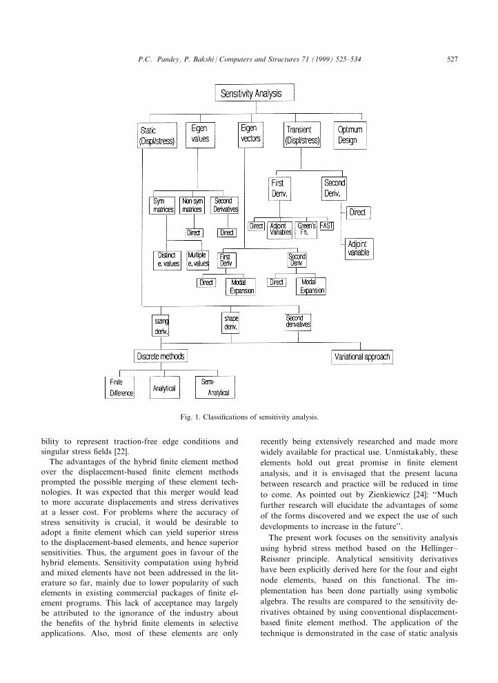
Fig. 1. Classi®cations of sensitivity analysis.
P.C. Pandey, P. Bakshi / Computers and Structures 71 (1999) 525±534 527
of two-dimensional problems of elasticity with respect
to sizing variables.
2. Response sensitivity
2.1. General de®nition and classi®cation
In analysis problems, there is a need to study thee�ect of the variation of design variables or variationof some parameters that characterizes (globally or
locally) the response, such as stress or displacementstates. Corresponding variations in response caused bydesign perturbation constitute the study matter of de-
sign sensitivity analysis. The sensitivity analysis maythus be de®ned as the methods for obtaining the ratesof change of response quantities due to variations in
design variables. In a structural sense, response quan-tities are simply the derived quantities like displace-ment, stress, eigenvalue/eigenvector, buckling load,natural frequency and interlaminar stresses, and failure
indices for composites. On the other hand, the designvariables may be de®ned as those components of astructure that de®ne the topology and geometry of the
system being analysed.From the point of view of response quantities, sensi-
tivity derivatives can be classi®ed into several classes.
If the e�ect of change of displacements or strains on abehavioural function are to be examined with respectto any design variable, the corresponding terms are dis-
placement sensitivity or strain sensitivity, respectively.
Similarly, considering stresses, one can obtain the
stress sensitivity. On similar lines, the eigenvalue and
eigenvector sensitivities, buckling load sensitivity, fre-
quency response sensitivity and so on, have been
de®ned in the literature [19,20]. Another classi®cation
of the sensitivity methods can be made with respect to
design variables which are being varied in order to
study the corresponding variations in response quan-
tities. Thus, there are the sizing sensitivity and the
shape sensitivity according as the design variables are,
respectively, sizing variables and shape variables.
Finally, sensitivity gradients may be categorized
depending upon the methods used to compute the
same.
From the formulation point of view, sensitivity
analysis of structural response has followed two paral-
lel paths. The ®rst path involves the application of sen-
sitivity techniques to an already discretized system and
is known as the discrete approach. The other path is
concerned with the di�erentiation of the continuum
equations which were then discretized. This was termed
the variational method. The various types of sensitivity
derivatives and their analysis techniques are brie¯y
summarized in Fig. 1. They have been reviewed
[20,21,26] in detail elsewhere.
The displacement sensitivities for discrete static sys-
tems can be obtained from the static equation of equi-
librium, as follows:
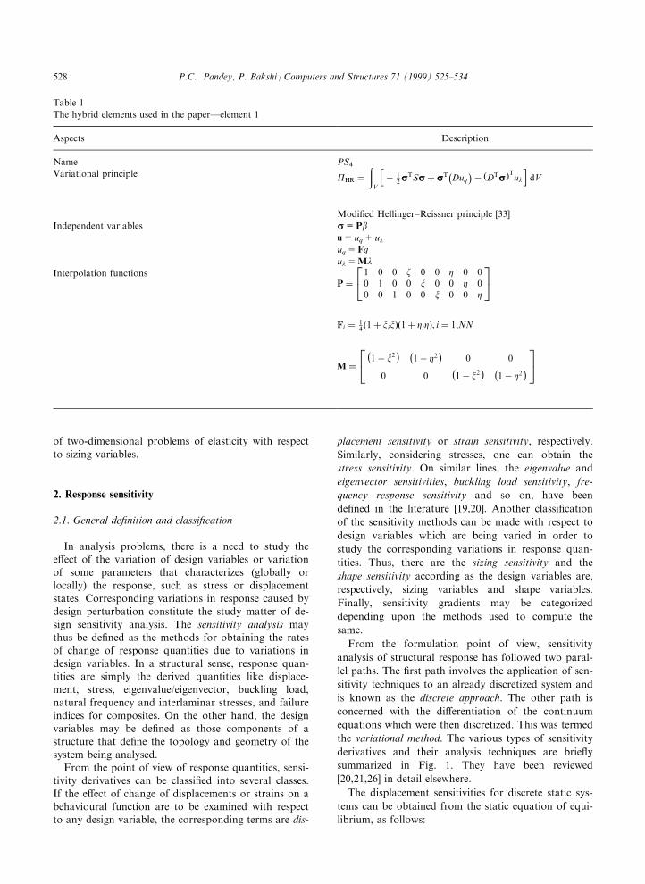
Table 1
The hybrid elements used in the paperÐelement 1
Aspects Description
Name PS4
Variational principle PHR ��V
hÿ 1
2sssTSsss� sssTÿDuq
�ÿ �DTsss�Tuli
dV
Modi®ed Hellinger±Reissner principle [33]
Independent variables ss=Pbu=uq+uluq=Fq
ul=MlInterpolation functions
P �24 1 0 0 x 0 0 Z 0 00 1 0 0 x 0 0 Z 00 0 1 0 0 x 0 0 Z
35Fi � 1
4 �1� xix��1� ZiZ�, i � 1,NN
M �24ÿ1ÿ x2
� ÿ1ÿ Z2
�0 0
0 0ÿ1ÿ x2
� ÿ1ÿ Z2
�35
P.C. Pandey, P. Bakshi / Computers and Structures 71 (1999) 525±534528
�K�b��fqg � �F�b� �1�
where [K ] is the sti�ness matrix of size n�n, {q } is the
displacement vector of size n� 1, {F } is the externalload vector of size n�1, {b } is the vector of designvariables of size m� 1.
Di�erentiating Eq. (1), we get
�K ��@q
@bi
���@F
@bi
�ÿ�@ �K �@bi
�fqg �2�
The right-hand side is known as the ``Pseudo Load''
vector, denoted P�. Once P� is calculated, the displace-ment sensitivity, @q/@bi can be easily obtained by con-ventional ®nite element analysis. Having obtained the
displacement derivatives, the stress and strain sensi-tivities can be obtained easily.In hybrid ®nite element formulation, besides interpo-
lating the stresses in terms of unknown coe�cients, b,the element displacements, u, are separated into twoparts: the compatible part uq which is expressed in
terms of the nodal displacements, q, and the additional
part ul, which is expressed in terms of the internal dis-
placement parameters, l. Here, the equilibrium of the
stresses is coerced within each element only in an aver-
age sense. Thus, a purely stress-based approach was
formally derived. Current variational bases for ®nite el-
ement formulations are embedded in the most general
Hu±Washizu functional in which displacements, stres-
ses and strains are all assumed as independent quan-
tities. Based on a variational functional introduced by
Chien [27], proposing the separation of the stress
terms, also, Chen and Cheung [25,28±31] presented a
series of element formulations, with all three quan-
titiesÐdisplacements, stresses and strains indepen-
dently interpolated.
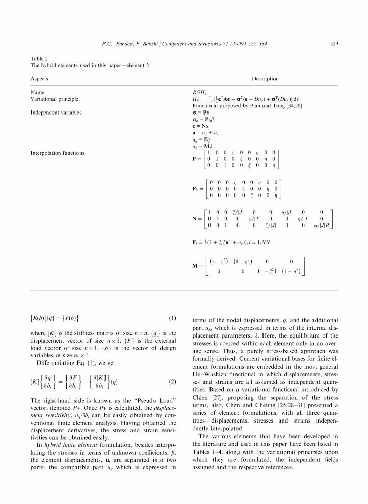
The various elements that have been developed in
the literature and used in this paper have been listed in
Tables 1±4, along with the variational principles upon
which they are formulated, the independent ®elds
assumed and the respective references.
Table 2
The hybrid elements used in this paperÐelement 2
Aspects Description
Name RGH4
Variational principle PG ��V � 12EEETAEEEÿ sssT�EEEÿDuq� � sssT
h �Dul�� dVFunctional proposed by Pian and Tong [34,28]
Independent variables ss=Pbssh=PhbEE=Nau=uq+uluq=Fq
ul=MlInterpolation functions
P �24 1 0 0 x 0 0 Z 0 00 1 0 0 x 0 0 Z 00 0 1 0 0 x 0 0 Z
35
Ph �24 0 0 0 x 0 0 Z 0 00 0 0 0 x 0 0 Z 00 0 0 0 0 x 0 0 Z
35
N �24 1 0 0 x=jJj 0 0 Z=jJj 0 00 1 0 0 x=jJj 0 0 Z=jJj 00 0 1 0 0 x=jJj 0 0 Z=jJjB
35Fi � 1
4 �1� xix��1� ZiZ�, i � 1,NN
M �24ÿ1ÿ x2
� ÿ1ÿ Z2
�0 0
0 0ÿ1ÿ x2
� ÿ1ÿ Z2
�35
P.C. Pandey, P. Bakshi / Computers and Structures 71 (1999) 525±534 529
3. Analytical sensitivity using hybrid elements
Considering the modi®ed functional proposed by Cheung and Chen [25], as
PG �Xe
�V e
�1
2EEETAEEEÿ sssTÿEEEÿDuq
�� sssTh �Dul�
�dV �3�
where u=uq+ ul, uq=the compatible part of the displacement vector u, ul=the incompatible part of the displace-
ment vector, EE=the strain vector, ss=the stress vector, ssh=the stress vector with the constant terms excluded,and A=elasticity matrix.Admissible variations of Eq. (3) and static condensation of the parameters corresponding to the internal displace-
ments at the element level lead to the formulation of the sti�ness matrix of a new hybrid element as follows:
K � G TqW
ÿTHW ÿ1hIÿ Gl
ÿG T
lWÿTHW ÿ1Gl
�ÿ1G T
lWÿTHW ÿ1
iGq �4�
In order to calculate the displacement sensitivity, from Eq. (2), one needs to calculate the pseudo load vector, whichcomprises the derivatives of the load vector as well as the sti�ness matrix, with respect to some design variables.Thus, di�erentiation of the hybrid sti�ness matrix, K, with respect to any design parameter, b, would yield
@K
@b� @G T
q
@b�W ÿTHW ÿ1 �
hIÿ Gl
ÿG T
lWÿTHW ÿ1Gl
�ÿ1G T
lWÿTHW ÿ1
iGq � G T
q
@
@b�W ÿTHW ÿ1 �
�hIÿ Gl
ÿG T
lWÿTHW ÿ1Gl
�ÿ1G T
lWÿTHW ÿ1
iGq � G T
q�W ÿTHW ÿ1 �
� @
@b
hIÿ Gl
ÿG T
lWÿTHW ÿ1Gl
�ÿ1G T
lWÿTHW ÿ1
iGq � G T
q�W ÿTHW ÿ1 �
�hIÿ Gl
ÿG T
lWÿTHW ÿ1Gl
�ÿ1G T
lWÿTHW ÿ1
i@
@b
�5�
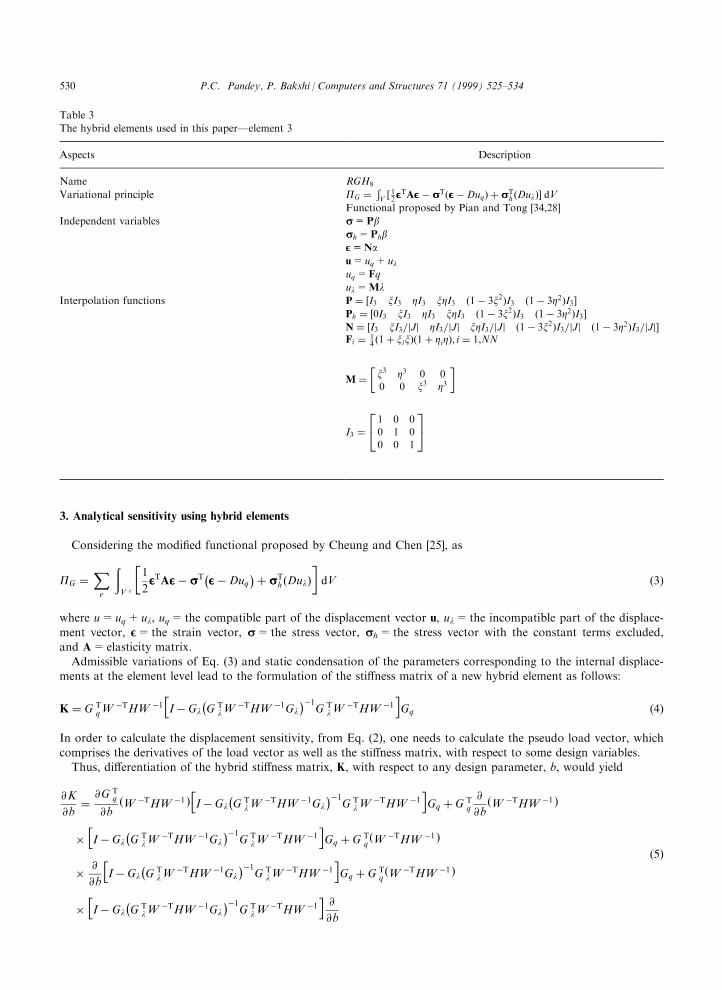
Table 3
The hybrid elements used in this paperÐelement 3
Aspects Description
Name RGH8
Variational principle PG ��V � 12EEETAEEEÿ sssT�EEEÿDuq� � sssT
h �Dul�� dVFunctional proposed by Pian and Tong [34,28]
Independent variables ss=Pbssh=PhbEE=Nau=uq+uluq=Fq
ul=MlInterpolation functions P � �I3 xI3 ZI3 xZI3 �1ÿ 3x2�I3 �1ÿ 3Z2�I3�
Ph � �0I3 xI3 ZI3 xZI3 �1ÿ 3x2�I3 �1ÿ 3Z2�I3�N � �I3 xI3=jJj ZI3=jJj xZI3=jJj �1ÿ 3x2�I3=jJj �1ÿ 3Z2�I3=jJj�Fi � 1
4 �1� xix��1� ZiZ�, i � 1,NN
M ��x3 Z3 0 00 0 x3 Z3
�
I3 �24 1 0 00 1 00 0 1
35
P.C. Pandey, P. Bakshi / Computers and Structures 71 (1999) 525±534530
From the above expression, it is clear that, in order to obtain the derivative of the sti�ness matrix, it would berequired to evaluate the derivatives of the matrices H, Wÿ1, Gq and Gl, with respect to the design variable b.The load vector is, generally, not a function of either shape or sizing variables, except in the case of directed
loads. Hence, assuming the derivative of the load vector to be zero, the displacement derivative with respect to thedesign variable, b, can be obtained by substituting Eq. (5) into Eq. (2).Having obtained the displacement derivatives, the derivatives of the strain and the stress parameters, a and b can
be easily obtained. From the formulation of the element [25], the dependence of the stress and the strain parameters
on the displacement parameters can be given as:
b �W ÿTHW ÿ1hIÿ Gl
ÿG T
lWÿTHW ÿ1Gl
�ÿ1G T
lWÿTHW ÿ1
iGqq �6�
and
a �W ÿ1hIÿ Gl
ÿG T
lWÿTHW ÿ1Gl
�ÿ1G T
lWÿTHW ÿ1
iGqq �7�
Di�erentiating Eqs. (6) and (7), with respect to b,
Table 4
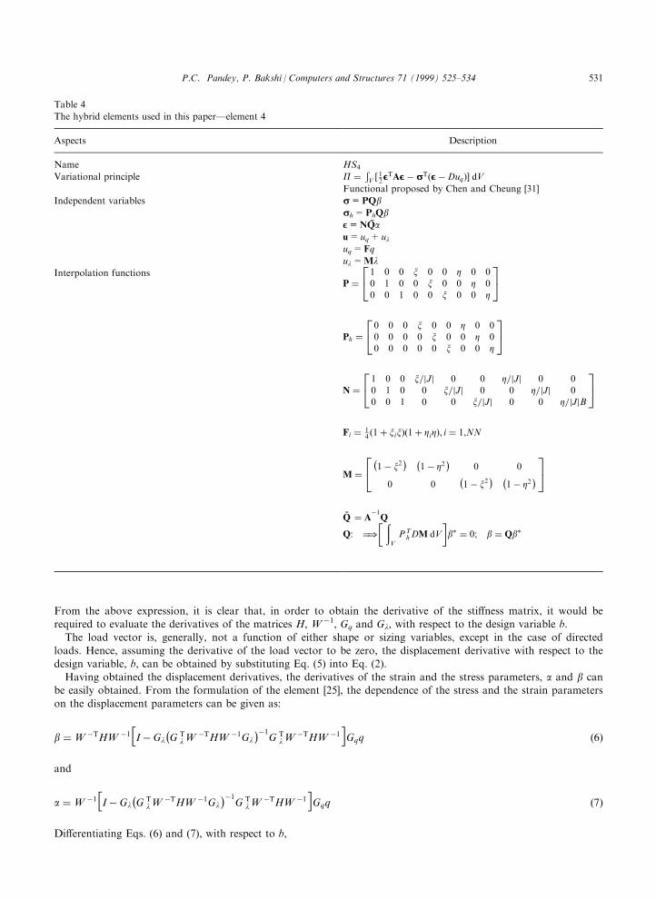
The hybrid elements used in this paperÐelement 4
Aspects Description
Name HS4
Variational principle P � �V � 12EEETAEEEÿ sssT�EEEÿDuq�� dV
Functional proposed by Chen and Cheung [31]
Independent variables ss=PQbssh=PhQbEE=NQau=uq+uluq=Fq
ul=MlInterpolation functions
P �24 1 0 0 x 0 0 Z 0 00 1 0 0 x 0 0 Z 00 0 1 0 0 x 0 0 Z
35
Ph �24 0 0 0 x 0 0 Z 0 00 0 0 0 x 0 0 Z 00 0 0 0 0 x 0 0 Z
35
N �24 1 0 0 x=jJj 0 0 Z=jJj 0 00 1 0 0 x=jJj 0 0 Z=jJj 00 0 1 0 0 x=jJj 0 0 Z=jJjB
35Fi � 1
4 �1� xix��1� ZiZ�, i � 1,NN
M �24ÿ1ÿ x2
� ÿ1ÿ Z2
�0 0
0 0ÿ1ÿ x2
� ÿ1ÿ Z2
�35
ÅQ � Aÿ1
Q
Q: �)� �
V
PThDM dV
�b� � 0; b � Qb�
P.C. Pandey, P. Bakshi / Computers and Structures 71 (1999) 525±534 531
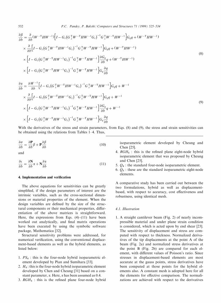
@b@b� @
@b�W ÿTHW ÿ1 �
hIÿ Gl
ÿG T
lWÿTHW ÿ1Gl
�ÿ1G T
lWÿTHW ÿ1
iGqq� �W ÿTHW ÿ1 �
� @
@b
hIÿ Gl
ÿG T
lWÿTHW ÿ1Gl
�ÿ1G T
lWÿTHW ÿ1
iGqq� �W ÿTHW ÿ1 �
�hIÿ Gl
ÿG T
lWÿTHW ÿ1Gl
�ÿ1G T
lWÿTHW ÿ1
i@Gq
@bq� �W ÿTHW ÿ1 �
�hIÿ Gl
ÿG T
lWÿTHW ÿ1Gl
�ÿ1G T
lWÿTHW ÿ1
iGq@q
@b
�8�
@a@b� @W ÿ1
@b
hIÿ Gl
ÿG T
lWÿTHW ÿ1Gl
�ÿ1G T
lWÿTHW ÿ1
iGqq�W ÿ1
� @
@b
hIÿ Gl
ÿG T
lWÿTHW ÿ1Gl
�ÿ1G T
lWÿTHW ÿ1
iGqq�W ÿ1
�hIÿ Gl
ÿG T
lWÿTHW ÿ1Gl
�ÿ1G T
lWÿTHW ÿ1
i@Gq
@bq�W ÿ1
�hIÿ Gl
ÿG T
lWÿTHW ÿ1Gl
�ÿ1G T
lWÿTHW ÿ1
iGq@q
@b
�9�
With the derivatives of the stress and strain parameters, from Eqs. (8) and (9), the stress and strain sensitivities can
be obtained using the relations from Tables 1±4. Thus,
@s@b� @P
@bb� P
@b@b
�10�
and
@ E@b� @N
@ba� N
@a@b
�11�
4. Implementation and veri®cation
The above equations for sensitivities can be greatly
simpli®ed, if the design parameters of interest are theintrinsic variables, such as the cross-sectional dimen-sions or material properties of the element. When the
design variables are de®ned by the size of the struc-tural components or their mechanical properties, di�er-entiation of the above matrices is straightforward.
Here, the expressions from Eqs. (4)±(11) have beenworked out analytically, and ®nal matrix operationshave been executed by using the symbolic software
package, Mathematica [32].Structural sensitivity problems were addressed, for
numerical veri®cation, using the conventional displace-ment-based elements as well as the hybrid elements, as
listed below:
1. PS4 : this is the four-node hybrid isoparametric el-
ement developed by Pian and Sumihara [33].2. H4 : this is the four-node hybrid isoparametric element
developed by Chen and Cheung [31] based on a con-
stant parameter, a. Here, a has been assumed as 0.4.3. RGH4 : this is the re®ned plane four-node hybrid
isoparametric element developed by Cheung andChen [25].
4. RGH8 : this is the re®ned plane eight-node hybridisoparametric element that was proposed by Cheungand Chen [25].
5. Q4 : the standard four-node isoparametric element.6. Q8 : these are the standard isoparametric eight-node
elements.
A comparative study has been carried out between thetwo formulations, hybrid as well as displacement-based, with respect to accuracy, cost e�ectiveness and
robustness, using identical mesh.
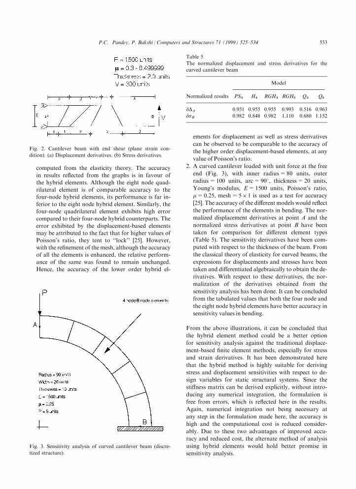
4.1. Illustration
1. A straight cantilever beam (Fig. 2) of nearly incom-pressible material and under plane strain conditionis considered, which is acted upon by end shear [23].
The sensitivity of displacement and stress are com-puted with respect to thickness. Normalized deriva-tives of the tip displacements at the point A of thebeam (Fig. 2a) and normalized stress derivatives at
the point B (Fig. 2b) are compared for each el-ement, with di�erent values of Poisson's ratio. Sincestresses in displacement-based elements are most
accurate at the gauss points, stress derivatives havebeen computed at those points for the hybrid el-ements also. A constant mesh is adopted here for all
the elements for e�ective comparison. The normali-zations are achieved with respect to the derivatives
P.C. Pandey, P. Bakshi / Computers and Structures 71 (1999) 525±534532
computed from the elasticity theory. The accuracy
in results re¯ected from the graphs is in favour of
the hybrid elements. Although the eight node quad-
rilateral element is of comparable accuracy to the
four-node hybrid elements, its performance is far in-
ferior to the eight node hybrid element. Similarly, the
four-node quadrilateral element exhibits high error
compared to their four-node hybrid counterparts. The
error exhibited by the displacement-based elements
may be attributed to the fact that for higher values of
Poisson's ratio, they tent to ``lock'' [25]. However,
with the re®nement of the mesh, although the accuracy
of all the elements is enhanced, the relative perform-
ance of the same was found to remain unchanged.
Hence, the accuracy of the lower order hybrid el-
ements for displacement as well as stress derivatives
can be observed to be comparable to the accuracy of
the higher order displacement-based elements, at any
value of Poisson's ratio.
2. A curved cantilever loaded with unit force at the free
end (Fig. 3), with inner radius=80 units, outer
radius=100 units, arc=908, thickness=20 units,
Young's modulus, E=1500 units, Poisson's ratio,
m=0.25, mesh=5�1 is used as a test for accuracy
[25]. The accuracy of the di�erent models would re¯ect
the performance of the elements in bending. The nor-
malized displacement derivatives at point A and the
normalized stress derivatives at point B have been
taken for comparison for di�erent element types
(Table 5). The sensitivity derivatives have been com-
puted with respect to the thickness of the beam. From
the classical theory of elasticity for curved beams, the
expressions for displacements and stresses have been
taken and di�erentiated algebraically to obtain the de-
rivatives. With respect to these derivatives, the nor-
malization of the derivatives obtained from the
sensitivity analysis has been done. It can be concluded
from the tabulated values that both the four node and
the eight node hybrid elements have better accuracy in
sensitivity values in bending.
From the above illustrations, it can be concluded that
the hybrid element method could be a better option
for sensitivity analysis against the traditional displace-
ment-based ®nite element methods, especially for stress
and strain derivatives. It has been demonstrated here
that the hybrid method is highly suitable for deriving
stress and displacement sensitivities with respect to de-
sign variables for static structural systems. Since the
sti�ness matrix can be derived explicitly, without intro-
ducing any numerical integration, the formulation is
free from errors, which is re¯ected here in the results.
Again, numerical integration not being necessary at
any step in the formulation made here, the accuracy is
high and the computational cost is reduced consider-
ably. Due to these two advantages of improved accu-
racy and reduced cost, the alternate method of analysis
using hybrid elements would hold better promise in
sensitivity analysis.
Fig. 2. Cantilever beam with end shear (plane strain con-
dition). (a) Displacement derivatives. (b) Stress derivatives.
Fig. 3. Sensitivity analysis of curved cantilever beam (discre-
tized structure).
Table 5
The normalized displacement and stress derivatives for the
curved cantilever beam
Model
Normalized results PS4 H4 RGH4 RGH8 Q4 Q8
dDA 0.951 0.955 0.955 0.993 0.516 0.963
dsB 0.982 0.848 0.982 1.110 0.680 1.152
P.C. Pandey, P. Bakshi / Computers and Structures 71 (1999) 525±534 533
5. Conclusions
Response sensitivity using the hybrid elementmethod has been presented. Sensitivity expressions arederived explicitly and implemented, using symbolic
algebra partially. The results of the numerical exper-imentation are encouraging and demonstrate the su-perior performance of hybrid elements in sensitivity
computations. Here, attention has been focused mainlyon sizing sensitivity. Shape sensitivity using hybrid el-ements requires further investigation. Further investi-
gation is also warranted to compute sensitivities ofother derived quantities, like eigenvalue/eigenvectorsfor both shape and sizing variables.
References
[1] Dems K, Mro z Z. Variational approach by means of
adjoint systems to structural optimization and sensitivity
analysisÐI. Int J Solids Struct 1983;19(8):677±92.
[2] Dems K, Mro z Z. Variational approach by means of
adjoint systems to structural optimization and sensitivity
analysisÐII. Int J Solids Struct 1984;20(6):527±52.
[3] Dems K, Mro z Z. Variational approach to ®rst and sec-
ond order sensitivity analysis of elastic structures. Int J
Numer Meth Engng 1985;21:637±61.
[4] Choi KK, Chang KM. A study of design velocity ®eld
computation for shape optimal design. Finite Elem Anal
Des 1994;15:317±41.
[5] Choi KK, Santos JLT, Frederick MC. Implementation of
design sensitivity analysis with existing ®nite element codes.
ASME JMech TransmAutomDes 1987;109:385±91.
[6] Haftka RT. Sensitivity calculations for iteratively solved
problems. Int J Numer Meth Engng 1985;21:1535±46.
[7] Haftka RT, Barthelemy B. On the accuracy of shape sen-
sitivity. In: Brebbia CA, Hernandes S. editors. Computer
aided optimum design of structures: recent advances.
Springer Verlag, 1989. p. 327±36.
[8] Arora JS, Haug EJ. Methods of design sensitivity analy-
sis in structural optimization. AIAA J 1979;17(9):970±4.
[9] Belegundu AD. MuÇ ller±Breslau's principle in adjoint de-
sign sensitivity analysis. Mech Struct Mach
1989;17(3):333±47.
[10] Rajan SD, Belegundu AD. Shape optimization using ®c-
titious loads. AIAA J 1989;27(1):102±7.
[11] Wang SY, Sun Y, Gallagher RH. Sensitivity analysis in
shape optimization of continuum structures. Comput
Struct 1985;20(5):855±67.
[12] Gopalkrisnan HS, Greimann LF. Newton±Raphson pro-
cedure for the sensitivity analysis of non-linear structural
behavior. Comput Struct 1988;30(6):1263±73.
[13] Tsay JJ, Arora JS. Non-linear design sensitivity analysis
for path dependent problems. Part I: general theory.
Comput Meth Appl Mech Engng 1990;81:183±208.
[14] Tsay JJ, Arora JS. Non-linear design sensitivity analysis
for path dependent problems. Part II: analytical
examples. Comput Meth Appl Mech Engng 1990;81:209±
28.
[15] Tortorelli DA. Sensitivity analysis for non-linear con-
strained elastostatic systems. Int J Numer Meth Engng
1992;33:1643±60.
[16] Chen JL, Ho JS. Direct variational method for sizing de-
sign sensitivity analysis of beam and frame structures.
Comput Struct 1992;42(4):503±9.
[17] Stone TA, Santos JLT, Haug EJ. An interactive pre-pro-
cessor for structural design sensitivity and optimization.
Comput Struct 1990;34:375±85.
[18] Santos JLT, Godse MM, Chang KH. An interactive
post-processor for structural design sensitivity analysis
and optimization: sensitivity display and what-if study.
Comput Struct 1990;35(1):1±13.
[19] Adelman HM, Haftka RT. Sensitivity analysis of discrete
structural systems. AIAA J 1986;24:823±32.
[20] Haftka RT, Adelman HM. Recent developments in
structural sensitivity analysis. Struct Opt 1989;1:137±51.
[21] Pandey PC, Bakshi P. Structural response sensitivity
computationÐan evaluation. In: Parthan S, Sinha PK,
editors. Computational Structural Mechanics. Proceedings
of the National Seminar on Aero StructuresÐ94. New
Delhi: Allied Publishers Ltd, 1994. p. 3±12.
[22] Pian THH. Hybrid models. In: Fenves SJ, Robinson
AR, Perrone N, Schnobrich WC, editors. Numerical and
computer methods in structural mechanics. Academic
Press, 1973. p. 59±78.
[23] Pian THH. Derivation of element sti�ness matrices by
assumed stress distributions. AIAA J 1964;2(7):1333±6.
[24] Zienkiewicz OC, Taylor RC The ®nite element method.
Volume 1, 4th ed. Maidenhead: McGraw-Hill, 1987.
[25] Cheung YK, Chen W. Re®ned hybrid method for plane
isoparametric element using an orthogonal approach.
Comput Struct 1992;42(5):683±94.
[26] Haug EJ, Choi KK, Kromkov V. Design sensitivity
analysis of structural systems. New York: Academic
Press, 1986.
[27] Chien WZ. Method of high-order Lagrange multiplier
and generalized variational principles of elasticity with
more general forms of functionals. In: Applied
Mathematical Mechanics, vol. 4. China, EUST Press:
Wuhan, 1983. p. 137±50.
[28] Chen WJ, Cheung YK. A new approach for the hybrid
element method. Int J Numer Meth Engng
1987;24:1697±709.
[29] Cheung YK, Chen W. Isoparametric hybrid hexahedral
elements for three dimensional stress analysis. Int J
Numer Meth Engng 1988;26:677±93.
[30] Cheung YK, Chen W. Hybrid element method for
incompressible and nearly incompressible materials. Int J
Solids Struct 1989;25(5):483±95.
[31] Chen WJ, Cheung YK. A robust re®ned quadrilateral
plane element. Int J Numer Meth Engng 1995;38:649±66.
[32] Gray J. Mastering MATHEMATICA: programming
methods and applications, 1994.
[33] Pian THH, Sumihara K. Rational approach for assumed
stress ®nite elements. Int J Numer Meth Engng
1984;20:1685±95.
[34] Pian THH, Tong P. Relations between incompatible dis-
placement model and hybrid stress model. Int J Numer
Meth Engng 1984;22:173±81.
P.C. Pandey, P. Bakshi / Computers and Structures 71 (1999) 525±534534


![[Marvin Lee Minsky] Computation, Finite and Infini(BookZZ.org)](https://img.pdfslide.us/doc/110x75/55cf932d550346f57b9c6c7d/marvin-lee-minsky-computation-finite-and-infinibookzzorg.jpg)