Embed Size (px)
Citation preview

ANALYTICAL RANDOM VIBRATION ANALYSIS OF
BOUNDARY-EXCITED THIN RECTANGULAR PLATES
ASHKAN HAJI HOSSEINLOO*,‡ and FOOK FAH YAP†
School of Mechanical and Aerospace EngineeringNanyang Technological University
50 Nanyang Avenue, Singapore 639798*[email protected]†[email protected]
NADER VAHDATI
Department of Mechanical Engineering
The Petroleum Institute
PO Box 2533 Abu Dhabi, UAE
Received 4 April 2012
Accepted 6 June 2012
Published 5 March 2013
Fatigue life, stability and performance of majority of the structures and systems depend sig-
ni¯cantly ondynamic loadings applied on them. Inmany engineering cases, the dynamic loading is
random vibration and the structure is a plate-like system. Examples could be printed circuitboards or jet impingement cooling systems subjected to random vibrations in harsh military
environments. In this study, the response of thin rectangular plates to random boundary exci-
tation is analytically formulated and analyzed. In the presentedmethod, closed-formmode shapes
are used and some of the assumptions in previous studies are eliminated; hence it is simpler andreduces the computational load. In addition, the e®ects of di®erent boundary conditions, modal
damping and excitation frequency range on dynamic random response of the system are studied.
The results show that increasingboth themodal damping ratio and the excitation frequency range
will decrease the root mean square acceleration and the maximum de°ection of the plate.
Keywords: Random vibration; boundary excitation; rectangular; thin plate.
1. Introduction
Fatigue life, stability and performance of majority of the structures and systems
depend signi¯cantly on dynamic loadings applied on them. A common type of
loading is random excitation which often occurs in earthquakes or other harsh
conditions like those in military environments. According to US Air-Force database,
‡Corresponding author.
International Journal of Structural Stability and DynamicsVol. 13, No. 3 (2013) 1250062 (16 pages)
#.c World Scienti¯c Publishing Company
DOI: 10.1142/S0219455412500629
1250062-1
Int.
J. S
tr. S
tab.
Dyn
. Dow
nloa
ded
from
ww
w.w
orld
scie
ntif
ic.c
omby
155
.69.
2.11
on
03/0
6/13
. For
per
sona
l use
onl
y.
20% of all the failures observed in electronic equipment are due to vibration problems
which are essentially random in nature.1,2 In order to prevent catastrophic and
fatigue failures or overdesign costs, an analytical random vibration analysis of these
structures seems to be very helpful for their optimum design. Fortunately, many
parts and components of the systems subjected to random vibration are of a rec-
tangular shape. Examples are the walls and °oors of buildings subjected to lateral
and vertical components of an earthquake motion, respectively, or printed circuit
boards subjected to random transportation vibration. Moreover, many of the sys-
tems like the aforementioned examples are base and boundary-excited systems.
Therefore, it seems that an analytical random vibration analysis of boundary-excited
plates can signi¯cantly help the ¯eld.
Random vibration of thin plates has been studied for decades. However, few
studies have focused on boundary or base excitation. Moreover, the analyses done so
far on thin plates are either analytical with the simplest boundary conditions such as
simply supported edges or with substantially simplifying assumptions, or otherwise
the analyses are carried out by numerical or experimental approaches. Huang and
Kececioglu studied the response of a simpli¯ed printed circuit board to random base
excitation.3 They modeled the system as a thin plate with simply supported edges.
They neglected the input velocity terms when calculating cross correlation and cross
spectral density functions. Leibowitz studied the random vibro-acoustic response of a
rectangular clamped or simply supported plate to turbulent excitation.4 In his study,
he used Warburton's method for determining the natural frequencies of the clamped
plate. However, he used the mode shapes corresponding to a simply supported plate.
A year later, Sadasivan et al.5 used a similar but hybrid method where they used the
product of beam functions with clamped ends instead of the simplifying simply
supported mode shapes for the calculation of joint acceptance integrals. Elishakof6
studied random vibration of orthotropic plates with either clamped or simply sup-
ported edges where he used an approximate method for determining the probabilistic
response of the plate. He used a series of approximate modes of vibration which
satis¯ed the boundary conditions but not the ¯eld equations. Furthermore, Miao and
Ouyang7 used a normalized group of generalized Fourier functions which satis¯ed the
clamped boundary conditions to evaluate the response of the system under random
excitation. They concluded that in order to involve higher order modes, many more
terms must be included to give satisfactory results which in turn increase the com-
putational e®ort and time. Later Poltrak8 studied random vibration of a thin plate
with a very speci¯c boundary condition where the plate had mutually perpendicular
clamped and free edges.
Besides analytical methods, a great proportion of the studies on random vibration
of plates are carried out by the help of either numerical and modeling software or
experimental tests. Maymon9 developed an analytical method to evaluate the ran-
dom response of deterministic and indeterministic structures to random loadings.
However, for his method to function e±ciently, he required closed-form solutions for
A. H. Hosseinloo, F. F. Yap & N. Vahdati
1250062-2
Int.
J. S
tr. S
tab.
Dyn
. Dow
nloa
ded
from
ww
w.w
orld
scie
ntif
ic.c
omby
155
.69.
2.11
on
03/0
6/13
. For
per
sona
l use
onl
y.

natural frequencies, mode shapes and stress functions of the structure. Since these
functions were not available in closed-form even for a simple clamped thin plate, at
least at that time, he used the numerical Taylor expansion method. Finite element,
¯nite strip and experimental methods are some other methods that have been used to
evaluate and analyze random response of rectangular plates or plate-like structures
such as printed circuit boards or printed wiring boards.2,10�14
Problems involving rectangular plates fall into three distinct categories15: (a)
plates with all edges simply supported; (b) plates with a pair of opposite edges simply
supported; (c) plates which do not fall into any of the above categories. According to
the literature there is hitherto no analytical random vibration study done that deals
with boundary-excited thin plates with boundary conditions falling into the third
category. All random plate vibration studies are made with the assumption that the
edges are simply supported or are done numerically or empirically, or otherwise
complex series expansion methods for mode shape approximation which are not
exact and yet computationally heavy, are used. In 2009, Xing and Liu16 found exact
closed-form solutions for mode shapes of some of the boundary conditions in the third
category for the very ¯rst time. As mentioned, there is a gap in the analytical random
vibration analysis of plate-like structures with boundary conditions falling in the
third category. Furthermore, exact mode shapes of some of the boundary conditions
of this category are recently (at the time when this paper was written) developed.
Therefore, the authors were motivated to do an analytical study on random vibra-
tion of boundary-excited thin plates.
Application-wise, the main motivation of the current study (in addition to the
applications mentioned earlier) is the random vibration analysis of jet impingement
cooling systems. In this cooling system, there are nozzle and impingement plates. The
edges of the thin rectangular plates are assumed to be clamped and the plates sub-
jected to random boundary excitation. The vibration of either of the nozzle or
impingement plates can deteriorate the overall thermal performance of the sys-
tem.17,18 Therefore, it is essential to study the random vibration response of these
plates for further protection and thermal performance maintenance using di®erent
vibration isolation and protection techniques.
2. Theoretical Analysis
2.1. Mathematical formulation
Figure 1 shows a thin rectangular plate with general boundary conditions. a and b
are the length and width of the plate, and wbðtÞ and wðx; y; tÞ are displacements of
the boundary and de°ection (displacement relative to the boundary) of an arbitrary
point on the plate, respectively.
The governing dynamic equation of the plate is given by
�@ 2wa
@t2þ c
@w
@tþDr4w ¼ 0; ð1Þ
Analytical Random Vibration Analysis of Boundary-Excited Thin Rectangular Plates
1250062-3
Int.
J. S
tr. S
tab.
Dyn
. Dow
nloa
ded
from
ww
w.w
orld
scie
ntif
ic.c
omby
155
.69.
2.11
on
03/0
6/13
. For
per
sona
l use
onl
y.

where wa is absolute displacement of the plate and is given by
waðx; y; tÞ ¼ wbðtÞ þ wðx; y; tÞ: ð2ÞIn Eq. (1), � and c are areal density and viscous damping coe±cient per unit area,
respectively and D is the °exural rigidity of the plate. By substituting Eq. (2) into
Eq. (1) and rearranging the equation, one obtains
�@ 2w
@t2þ c
@w
@tþDr4w ¼ pðtÞ; ð3Þ
where,
pðtÞ ¼ ��w::bðtÞ: ð4ÞIn this study, three di®erent boundary conditions are studied, namely CCCC, SSCC
and SCCC where letters C and S represent clamped and simply supported boundary
conditions, respectively. The eigenvalue problem of these boundary conditions can be
shown to be self-adjoint,19 and thus the eigenfunctions of the eigenvalue problem will
be orthogonal. In other words, if the eigenfunctions of the mnth and klth modes are
designated as mn and kl, the following equations as orthogonality of the eigen-
functions hold true, ZR
� mnðx; yÞ klðx; yÞdxdy ¼ mmn�mn;kl ð5Þ
and ZR
c mnðx; yÞ klðx; yÞdxdy ¼ cmn�mn;kl; ð6Þ
where mmn and cmn are called modal mass and modal damping, respectively.
Since the plate is homogenous, � and c are constant over the plate's area and thus,
cmn ¼ c
�mmn: ð7Þ
In Eqs. (5) and (6), R is the integration domain (that is the plate's surface) and �mn;kl
is the Kronecker delta function and is de¯ned as,
�mn;kl ¼1; mn ¼ kl
0; mn 6¼ kl
�: ð8Þ
Fig. 1. Thin rectangular plate with coordinates and general boundary conditions.
A. H. Hosseinloo, F. F. Yap & N. Vahdati
1250062-4
Int.
J. S
tr. S
tab.
Dyn
. Dow
nloa
ded
from
ww
w.w
orld
scie
ntif
ic.c
omby
155
.69.
2.11
on
03/0
6/13
. For
per
sona
l use
onl
y.

Now the solution to Eq. (3) is assumed to have the form
wðx; y; tÞ ¼X1m¼1
X1n¼1
mnðx; yÞqmnðtÞ; ð9Þ
where qmnðtÞ is the time varying function.
By substituting Eq. (9) into Eq. (3) and then multiplying both sides of the
resultant equation by klðx; yÞ and integrating over the plate's surface, one obtains
€qmnðtÞ þ �mn _qmnðtÞ þ !2mnqmnðtÞ ¼
1
mmn
ZR
mnðx; yÞpðtÞdxdy; ð10Þ
where !mn is the undamped natural frequency of themnth mode of the plate and �mn
is the frequency bandwidth of the mnth mode and is de¯ned as,
�mn ¼ cmn
mmn
¼ 2�mn!mn; ð11Þ
where �mn is the modal damping ratio of the mnth mode.
The frequency response function of the plate at point ðx; yÞ, Hwðx; y; !Þ to the
input wbðtÞ can be calculated by applying a unit harmonic input as
wbðtÞ ¼ ei!t: ð12ÞThe substitution of Eq. (12) into Eq. (4) and in view of Eq. (10), one obtains
€qmnðtÞ þ �mn _qmnðtÞ þ !2mnqmnðtÞ ¼
�!2Imn
mmn
ei!t; ð13Þ
where
Imn ¼ZR
mnðx; yÞdxdy: ð14Þ
The solution of Eq. (13) may be written as
qmnðtÞ ¼ Hmnð!ÞImnei!t; ð15Þ
where
Hmnð!Þ ¼�!2
mmnð�!2 þ �mni!þ !2mnÞ
: ð16Þ
By substituting Eq. (15) into Eq. (9), one can ¯nd the frequency response function of
the plate's de°ection Hwðx; y; !Þ,
Hwðx; y; !Þ ¼X1m¼1
X1n¼1
mnðx; yÞHmnð!ÞImn: ð17Þ
Consequently, according to Eq. (2) the frequency response function of the plate's
absolute displacement Hwaðx; y; !Þ isHwa
ðx; y; !Þ ¼ 1þHwðx; y; !Þ: ð18Þ
Analytical Random Vibration Analysis of Boundary-Excited Thin Rectangular Plates
1250062-5
Int.
J. S
tr. S
tab.
Dyn
. Dow
nloa
ded
from
ww
w.w
orld
scie
ntif
ic.c
omby
155
.69.
2.11
on
03/0
6/13
. For
per
sona
l use
onl
y.

In view of the frequency response functions and the power spectral density of the
input, one can ¯nd the variances of the plate's de°ection and acceleration at di®erent
points. The input is considered ergodic and stationary with one-sided displacement
power spectral density (PSD) of Swbð!Þ and zero mean value. Hence, the mean square
de°ection of the plate at point ðx; yÞ can be calculated as
E½w2ðx; y; tÞ� ¼Z 1
0
jHwðx; y; !Þj2Swbð!Þd!: ð19Þ
Similarly, the mean square of the plate absolute acceleration at this point is given by
E½ €w 2aðx; y; tÞ� ¼
Z 1
0
!4jHwaðx; y; !Þj2Swb
ð!Þd!: ð20Þ
In Eqs. (19) and (20), the input excitation is shown as the power spectral density of
the input displacement while PSD is usually measured in terms of acceleration rather
than displacement. However, it is very easy to relate these two functions,
Swbð!Þ ¼ S €wb
ð!Þ!4
: ð21Þ
2.2. Eigenvalue equations and eigenfunctions
In the equations derived in Sec. 2.1, mnðx; yÞ is the undamped normal mode shape
or eigenfunction of the mnth mode. The mode shapes depend on the system and its
boundary condition. In this study, three boundary conditions are considered, namely
CCCC, SSCC and SCCC as illustrated in Fig. 2. The exact closed-form mode shapes
for these boundary conditions were ¯rst derived in 200916 and are summarized in
Table 1. The eigenvalue equations and normal mode shapes of these three boundary
conditions are listed in Table 1. Note that the normal mode shape of the CCCC plate
presented by Xing and Liu in Table 2 of their paper16 is slightly wrong but it is re-
derived and corrected herein.
In Table 1, k1 and k2 are de¯ned as
k1 ¼cos�1a� cosh�2a�2
�1sin�1a� sinh�2a
; ð22Þ
Fig. 2. Three di®erent boundary conditions of the plate.
A. H. Hosseinloo, F. F. Yap & N. Vahdati
1250062-6
Int.
J. S
tr. S
tab.
Dyn
. Dow
nloa
ded
from
ww
w.w
orld
scie
ntif
ic.c
omby
155
.69.
2.11
on
03/0
6/13
. For
per
sona
l use
onl
y.

and
k2 ¼cos �1b� cosh �2b�2�1
sin �1b� sinh �2b: ð23Þ
�1; �2; �1 and �2 are mode dependent unknowns. These unknowns along with the
undamped natural frequency of the plate can be determined by solving a set of ¯ve
nonlinear equations. Two out of the ¯ve equations are the eigenvalue equations in
Table 1 and the other three equations are as follows,
� 21 þ � 2
2 ¼ 2k2
�1 ¼ffiffiffiffiffiffiffiffiffiffiffiffiffiffiffiffik2 � � 2
1
p�2 ¼
ffiffiffiffiffiffiffiffiffiffiffiffiffiffiffiffik2 þ � 2
1
p
8><>: ; ð24Þ
where
k2 ¼ !mn
ffiffiffiffiffiffiffiffiffi�=D
p: ð25Þ
For details of the derivation of the above ¯ve equations, one can refer toRefs. 16 and 20.
In order to solve the nonlinear equations for the ¯ve unknowns, one can use the
Newton's method. According to the eigenvalue equations the intervals of �1a and �1b
can be determined as,
�1a 2 ðm�;m�þ 0:5�Þ; m ¼ 1; 2; . . .
�1b 2 ðn�;n�þ 0:5�Þ; n ¼ 1; 2; . . .: ð26Þ
Thus, the midpoint of these intervals can be considered as the initial values for �1
and �1 in the Newton's method, that is,
�1 ¼ðm�þ �=4Þ
a; m ¼ 1; 2; . . .
�1 ¼ðn�þ �4Þ
b; n ¼ 1; 2; . . .
8>><>>:
: ð27Þ
Table 1. Eigenvalue equations and normal mode shapes of CCCC, SSCC and SCCC plates.
Boundary
condition
Eigenvalue equation Normal mode shape ðx; yÞ
CCCC 1� cos�1a cosh�2a
sin�1a sinh�2a¼ �2
1 � �22
2�1�2
;
1� cos�1b cosh�2b
sin�1b sinh�2b¼ � 2
1 � � 22
2�1�2
� cos�1xþ �2
�1
k1 sin�1xþ cosh�2x� k1 sinh�2x
� �
� cos�1yþ�2�1
k2 sin�1yþ cosh�2y� k2 sinh�2y
� �
SSCC �2 tan�1a ¼ �1 tan�2a;
�2 tan�1b ¼ �1 tan�2bsin�1x� sin�1a
sinh�2asinh�2x
� �
sin�1y�sin�1b
sinh �2bsinh �2y
� �
SCCC �2 tan�1a ¼ �1 tan�2a;
1� cos�1b cosh�2b
sin�1b sinh�2b¼ � 2
1 � � 22
2�1�2
sin�1x� sin�1a
sinh�2asinh�2x
� �
� cos�1yþ�2�1
k2 sin�1yþ cosh�2y� k2 sinh�2y
� �
Analytical Random Vibration Analysis of Boundary-Excited Thin Rectangular Plates
1250062-7
Int.
J. S
tr. S
tab.
Dyn
. Dow
nloa
ded
from
ww
w.w
orld
scie
ntif
ic.c
omby
155
.69.
2.11
on
03/0
6/13
. For
per
sona
l use
onl
y.
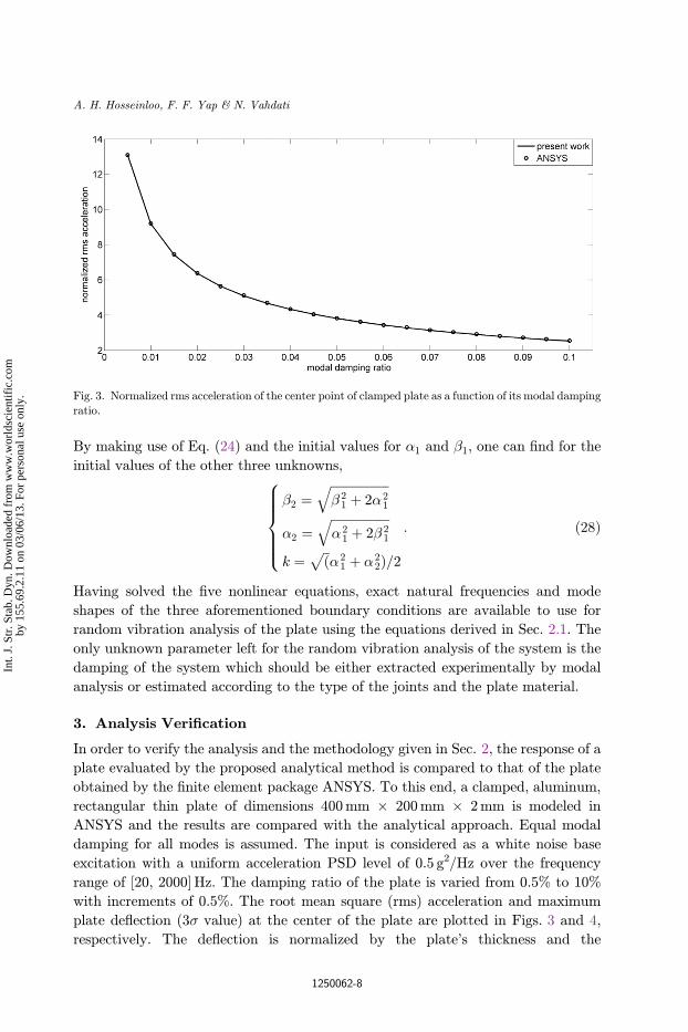
By making use of Eq. (24) and the initial values for �1 and �1, one can ¯nd for the
initial values of the other three unknowns,
�2 ¼ffiffiffiffiffiffiffiffiffiffiffiffiffiffiffiffiffiffiffi� 21 þ 2�2
1
q
�2 ¼ffiffiffiffiffiffiffiffiffiffiffiffiffiffiffiffiffiffiffi�2
1 þ 2� 21
q
k ¼ ffiffiðp�2
1 þ �22Þ=2
8>>>><>>>>:
: ð28Þ
Having solved the ¯ve nonlinear equations, exact natural frequencies and mode
shapes of the three aforementioned boundary conditions are available to use for
random vibration analysis of the plate using the equations derived in Sec. 2.1. The
only unknown parameter left for the random vibration analysis of the system is the
damping of the system which should be either extracted experimentally by modal
analysis or estimated according to the type of the joints and the plate material.
3. Analysis Veri¯cation
In order to verify the analysis and the methodology given in Sec. 2, the response of a
plate evaluated by the proposed analytical method is compared to that of the plate
obtained by the ¯nite element package ANSYS. To this end, a clamped, aluminum,
rectangular thin plate of dimensions 400mm � 200mm � 2mm is modeled in
ANSYS and the results are compared with the analytical approach. Equal modal
damping for all modes is assumed. The input is considered as a white noise base
excitation with a uniform acceleration PSD level of 0.5 g2/Hz over the frequency
range of [20, 2000] Hz. The damping ratio of the plate is varied from 0.5% to 10%
with increments of 0.5%. The root mean square (rms) acceleration and maximum
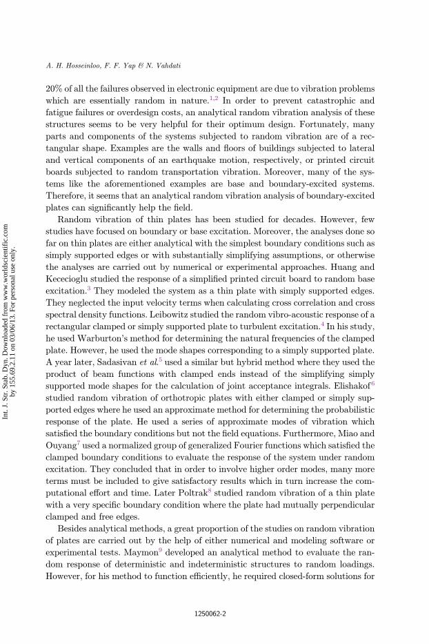
plate de°ection (3� value) at the center of the plate are plotted in Figs. 3 and 4,
respectively. The de°ection is normalized by the plate's thickness and the
Fig. 3. Normalized rms acceleration of the center point of clamped plate as a function of its modal damping
ratio.
A. H. Hosseinloo, F. F. Yap & N. Vahdati
1250062-8
Int.
J. S
tr. S
tab.
Dyn
. Dow
nloa
ded
from
ww
w.w
orld
scie
ntif
ic.c
omby
155
.69.
2.11
on
03/0
6/13
. For
per
sona
l use
onl
y.

acceleration is normalized by the rms acceleration of the excitation. According to
both ¯gures, analytical results agree well with those obtained from ANSYS, thereby
verifying the proposed method.
4. Numerical Results and Discussion
The same aluminum plate considered for the veri¯cation in Sec.3 is used here too for
presentation of numerical results. The plate has the same dimensions of 400mm �200mm � 2mm, where the long edge is parallel to the x axis, Young's modulus of
70GPa and Poisson ratio of 0.33. The modal damping ratio is considered constant
and equal to 3% unless otherwise speci¯ed. Three di®erent boundary conditions,
namely CCCC, SCCC and SSCC are considered.
Frequency response functions (FRF) of the plate's midpoint relative acceleration
for the three boundary conditions are plotted in Fig. 5 over the frequency range of
[20, 2000] Hz. It is very interesting that many modes (natural frequencies), obtained
from solving the ¯ve nonlinear equations, are missing in the FRF. For instance, for
the clamped plate there are seventeen modes in the frequency range of [20, 2000] Hz
where out of which only six are clearly shown in Fig. 5. This is due to the nature of
the boundary excitation. Referring to Eqs. (14) and (17), it can be stated that those
modes that have a nodal line passing through the point where FRF is being calcu-
lated or those that have zero mode shape integral will not show up in the FRF. The
latter condition includes the modes that the signed volume under their mode shapes
is zero. For the clamped plate, there are 11 modes with this property out of the ¯rst
17 modes making them disappear from the FRF.
Next, the plate is subjected to random boundary excitation with uniform PSD
level of 0.5 g2/Hz over the frequency range of [20, 2000] Hz. The selected frequency
range is the range commonly found in many military applications. Furthermore, PSD
Fig. 4. Normalized maximum de°ection of the center point of clamped plate as a function of its modal
damping ratio.
Analytical Random Vibration Analysis of Boundary-Excited Thin Rectangular Plates
1250062-9
Int.
J. S
tr. S
tab.
Dyn
. Dow
nloa
ded
from
ww
w.w
orld
scie
ntif
ic.c
omby
155
.69.
2.11
on
03/0
6/13
. For
per
sona
l use
onl
y.

level is set to 0.5 g2/Hz so as to achieve almost the upper bound limit of excitation
acceleration in many military applications, that is approximately 30 g. Figures 6 to 9
show the normalized rms acceleration and normalized maximum de°ection of dif-
ferent points of the clamped plate in surface and contour forms. These ¯gures are not
plotted for the other two boundary conditions since they have almost the same shape
and trend and they di®er only in the values. However, di®erent boundary conditions
will be compared later. According to Figs. 6 and 8, the ¯rst few modes contribute to
the acceleration response of the plate while Figs. 7 and 9 show that the dominant
mode for the plate de°ection is only the ¯rst mode. Referring to Eq. (21), this can be
Fig. 5. Frequency response function of the plate's midpoint j €W ðsÞ€W bðsÞj
� �.
Fig. 6. Normalized rms acceleration of the clamped plate over its surface.
A. H. Hosseinloo, F. F. Yap & N. Vahdati
1250062-10
Int.
J. S
tr. S
tab.
Dyn
. Dow
nloa
ded
from
ww
w.w
orld
scie
ntif
ic.c
omby
155
.69.
2.11
on
03/0
6/13
. For
per
sona
l use
onl
y.

justi¯ed since the PSD of the de°ection of a point on the plate decreases with power
four of the frequency as the frequency increases. Furthermore, referring to Figs. 6 to
9, the critical point where the plate's maximum de°ection and maximum accelera-
tion occur is the center of the plate. Hence, for the other ¯gures the response of the
plate only at its center is considered.
Di®erent materials have di®erent structural damping. Moreover, damping of a
structure with a selected material itself can vary due to the change in joints,
Fig. 8. Normalized rms acceleration contour of clamped plate.
Fig. 7. Normalized maximum de°ection of the clamped plate over its surface.
Analytical Random Vibration Analysis of Boundary-Excited Thin Rectangular Plates
1250062-11
Int.
J. S
tr. S
tab.
Dyn
. Dow
nloa
ded
from
ww
w.w
orld
scie
ntif
ic.c
omby
155
.69.
2.11
on
03/0
6/13
. For
per
sona
l use
onl
y.

temperature, and humidity or even due to aging. In order to observe the e®ect of
modal damping on the plate's response, it is varied from 0.5% to 10% with incre-
ments of 0.5% and the response of the plate is evaluated in terms of normalized rms
acceleration and normalized maximum de°ection. Since it was found that the critical
point for the plate's response is its center for both de°ection and acceleration, the
response of the plate is computed only at its center. Furthermore, to investigate the
e®ect of boundary conditions on the response of the plate, the plate's response is
plotted for the three boundary conditions.
Figures 10 and 11 show the normalized rms acceleration and normalized max-
imum de°ection of the center point of the plate, respectively. As it can be seen from
the ¯gures, both acceleration and de°ection of the plate decrease with respect to
increasing modal damping ratio. Moreover, referring to these ¯gures, the CCCC
plate has the largest acceleration and the SSCC plate has the smallest whereas the
SSCC plate has the largest de°ection and the CCCC plate has the smallest.
Therefore, it can be concluded that more clamped edges results in more rigidity of the
plate and, hence in larger acceleration and smaller de°ection.
As shown in Fig. 11, although the CCCC plate has smaller de°ection than the
SCCC plate, this di®erence is very small and thus negligible. However, this di®erence
in acceleration is not negligible as seen in Fig. 10. The reason is that for the
de°ection, the ¯rst mode is the dominant mode as discussed earlier, while for the
acceleration a few modes are contributing. Furthermore, the CCCC and the SCCC
plates have very close FRF around the ¯rst mode while they deviate at the higher
modes (referring to Fig. 5), hence resulting in almost equal de°ections but di®erent
accelerations.
Fig. 9. Normalized maximum de°ection contour of clamped plate.
A. H. Hosseinloo, F. F. Yap & N. Vahdati
1250062-12
Int.
J. S
tr. S
tab.
Dyn
. Dow
nloa
ded
from
ww
w.w
orld
scie
ntif
ic.c
omby
155
.69.
2.11
on
03/0
6/13
. For
per
sona
l use
onl
y.

The upper bound of operating frequency range of some military applications can
go as high as 5,000Hz such as in missiles.2 Consequently, if the application or
operating environment of a device is changed, its excitation frequency will be also
changed. Therefore, it seems useful to investigate the e®ect of the frequency range of
the excitation on the plate's response. However, in order to make it comparable, the
rms acceleration of the excitation (input power) is kept constant. To this end, the
starting frequency range of the excitation is ¯xed at 20Hz and the upper bound is
increased from 520Hz to 5020Hz with increments of 250Hz. The PSD level is uni-
form for any frequency range and it decreases as the frequency range increases so as
to keep the rms acceleration level of the excitation (input power) constant. The
modal damping ratio of the plate is considered constant at 3%.
Fig. 11. Normalized maximum de°ection of center point of plate as a function of its modal damping ratio
for the three boundary conditions.
Fig. 10. Normalized rms acceleration of center point of plate as a function of its modal damping ratio forthe three boundary conditions.
Analytical Random Vibration Analysis of Boundary-Excited Thin Rectangular Plates
1250062-13
Int.
J. S
tr. S
tab.
Dyn
. Dow
nloa
ded
from
ww
w.w
orld
scie
ntif
ic.c
omby
155
.69.
2.11
on
03/0
6/13
. For
per
sona
l use
onl
y.

Figures 12 and 13 show the normalized rms acceleration and normalized max-
imum de°ection of the center point of the plate as a function of the excitation
frequency range length. According to the ¯gures, as the frequency range broadens the
acceleration and the de°ection of the plate decrease. This is due to the fact that when
the frequency range broadens and the input power is kept constant, spectral power is
decreased for the low frequency modes and is added to the high frequency modes. In
general, higher modes contribute less than the lower ones to a system's response
especially to its de°ection. Therefore, broadening the excitation frequency range
decreases the acceleration and de°ection of the plate.
Fig. 13. Normalized maximum de°ection of centere point of plate as a function of the excitation frequency
range length for the three boundary conditions.
Fig. 12. Normalized rms acceleration of centere point of plate as a function of the excitation frequency
range length for the three boundary conditions.
A. H. Hosseinloo, F. F. Yap & N. Vahdati
1250062-14
Int.
J. S
tr. S
tab.
Dyn
. Dow
nloa
ded
from
ww
w.w
orld
scie
ntif
ic.c
omby
155
.69.
2.11
on
03/0
6/13
. For
per
sona
l use
onl
y.

5. Summary and Conclusion
In this study, an analytical random vibration analysis of boundary-excited thin
rectangular plates with di®erent boundary conditions was tackled. First the problem
was formulated and the mathematical equations were derived. Three boundary
conditions, namely CCCC, SCCC and SSCC whose closed-form mode shapes were
not found until 2009, were considered. The closed-form mode shapes of the CCCC
plate were corrected and then along with the other two boundary conditions were
used for the evaluation of the random response of the plates.
The study proves that many modes of the plate will not contribute to its
response due to the mathematics and nature of the boundary excitation. It
also shows that the center point of the plate is the critical point in terms of
maximum de°ection and maximum acceleration. Moreover, the study shows that
the very low frequency modes particularly the ¯rst mode is the dominant mode
for the de°ection of the plate while for the acceleration the ¯rst few modes will
contribute.
The e®ect of modal damping ratio, excitation frequency range, and boundary
condition were also studied. The results show that increasing both the modal
damping ratio and the excitation frequency range will decrease the rms acceleration
and the maximum de°ection of the plate. Furthermore, the results show that adding
the clamped edge will increase the rigidity of the plate as compared to the simply
supported edge and, hence increases the rms acceleration and decreases the max-
imum de°ection of the plate.
The novel method presented herein eliminates some of the assumptions of the
previous studies in the literature, yet simpli¯es the mathematics and, hence reduces
the computational e®ort. Moreover, the results presented herein can serve as
benchmark for future references.
Acknowledgment
The authors would like to gratefully acknowledge the ¯nancial support of the
Defence Science Organization (DSO).
References
1. D. S. Steinberg, Vibration Analysis for Electronic Equipment (John Wiley & Sons, Inc,USA, 1988).
2. M. I. Sakri et al., Estimation of fatigue-life of electronic packages subjected to randomvibration load, Defence Sci. J. 59 (2009) 58�62.
3. W. Huang, D. B. Kececioglu and J. L. Prince, A simpli¯ed random vibration analysis onportable electronic products, IEEE T. Compon. Pack. T. 23 (2000) 505�515.
4. R. C. Leibowitz, Vibroacoustic response of turbulence excited thin rectangular ¯niteplates in heavy and light °uid media, J. Sound Vib. 40 (1975) 441�495.
5. S. Sadasivan, K. Elango and R. C. Leibowitz, On computation of random response of aclamped plate, J. Sound Vib. 47 (1976) 129�132.
Analytical Random Vibration Analysis of Boundary-Excited Thin Rectangular Plates
1250062-15
Int.
J. S
tr. S
tab.
Dyn
. Dow
nloa
ded
from
ww
w.w
orld
scie
ntif
ic.c
omby
155
.69.
2.11
on
03/0
6/13
. For
per
sona
l use
onl
y.
6. I. Elishako®, Random vibrations of orthotropic plates clamped or simply supported allround, Acta Mech. 28 (1977) 165�176.
7. J. Miao and Y. Ouyang, The response of a clamped rectangular plate with viscousdamping and non-linear structural damping, Acta Mech. Sinica (1983) 469�479.
8. K. Poltorak, Vibration of plates with straight-line clamped and free edges, J. Sound Vib.104 (1986) 437�447.
9. G. Maymon, Random response of indeterministic structures subjected to stationaryrandom excitation, A practical engineering solution, J. Sound Vib. 172 (1994) 211�229.
10. R. L. Barnoski, Maximum response to random excitation of distributed structures withrectangular geometry, J. Sound Vib. 7(3) (1968) 333�350.
11. C. Sundararajan and D. V. Reddy, Response of rectangular orthotropic plates to randomexcitations, Int. J. Earthq. Eng. Struct. Dyn. 2 (1973) 161�170.
12. E. Suhir, Response of a °exible printed circuit board to periodic shock loads applied to itssupport contour, in 1992 ASME Summer Mechanics and Materials Meeting, 28 April1992�1 May (ASME, AZ, USA, 1992).
13. T. E. Wong et al., Development of BGA solder joint vibration fatigue life predictionmodel, in Proc. 49th Electronic Components and Technology Conf. 1�4 June (IEEE,Piscataway, NJ, USA, 1999).
14. T. E. Wong and H. S. Fenger, Vibration fatigue test of surface mount electronic com-ponents, in ASME Int. Electronic Packaging Technical Conf., Exhibition 6 July�11 July(Maui, HI, United States, 2003).
15. K. Bhaskar and B. Kaushik, Simple and exact series solutions for °exure of orthotropicrectangular plates with any combination of clamped and simply supported edges, Com-pos. Struct. 63 (2004) 63�68.
16. Y. Xing and B. Liu, New exact solutions for free vibrations of rectangular thin plates bysymplectic dual method, Acta Mech. Sinica 25 (2009) 265�270.
17. M.-Y. Wen, Flow structures and heat transfer of swirling jet impinging on a °at surfacewith micro-vibrations, Int. J. Heat Mass Tran. 48(3�4) (2005) 545�560.
18. H. Miyazaki and E. Silberman, Flow and heat transfer on a °at plate normal to a two-dimensional laminar jet issuing from a nozzle of ¯nite height, Int. J. Heat Mass Tran.15(11) (1972) 2097�2107.
19. L. Meirovitch, Analytical Methods in Vibrations (Prentice Hall, New York, 1967).20. Y. F. Xing and B. Liu, New exact solutions for free vibrations of thin orthotropic rec-
tangular plates, Compos. Struct. 89 (2009) 567�574.
A. H. Hosseinloo, F. F. Yap & N. Vahdati
1250062-16
Int.
J. S
tr. S
tab.
Dyn
. Dow
nloa
ded
from
ww
w.w
orld
scie
ntif
ic.c
omby
155
.69.
2.11
on
03/0
6/13
. For
per
sona
l use
onl
y.


![Elastic Analysis & Application Tables of Rectangular Plates [Artigo-papanikolaou]](https://img.pdfslide.us/doc/110x75/55cf9cb5550346d033aac39c/elastic-analysis-application-tables-of-rectangular-plates-artigo-papanikolaou.jpg)