Embed Size (px)
DESCRIPTION
Fracture
Citation preview
T
Ai
Da
b
c
a
ARRAA
KMfGA
1
fdamnsbcrmfbaw
Uf
(j
1h
Journal of Manufacturing Processes 14 (2012) 487–494
Contents lists available at SciVerse ScienceDirect
Journal of Manufacturing Processes
j ourna l ho me p age: www.elsev ier .com/ locate /manpro
echnical paper
nalytical prediction of stepped feature generation in multi-pass single pointncremental forming
ongkai Xua,b,1, Rajiv Malhotrab,1, N. Venkata Reddyc,2, Jun Chena,3, Jian Caoa,b,∗
Department of Plasticity Technology, Shanghai Jiao Tong University, 1954 Huashan Road, Shanghai, 200030, PR ChinaDepartment of Mechanical Engineering, Northwestern University, Evanston, IL 60208-3111, USADepartment of Mechanical Engineering, India Institute of Technology, Kanpur, Kanpur, Uttar Pradesh, 208016, India
r t i c l e i n f o
rticle history:eceived 9 July 2012eceived in revised form 8 August 2012ccepted 9 August 2012vailable online 20 September 2012
a b s t r a c t
Single point incremental forming (SPIF) is a new sheet metal forming process characterized by higherformability, product independent tooling and greater process flexibility. The inability of conventional sin-gle pass SPIF to form vertical walls without failure is overcome by forming multiple intermediate shapesbefore forming the final component, i.e., multi-pass single point incremental forming (MSPIF). A majorissue with MSPIF is significant geometric inaccuracy of the formed component, due to the generation of
eywords:ulti-pass single point incremental
orming (MSPIF)eometric accuracynalytical formulations
stepped features on the base. This work proposes analytical formulations that are shown to accuratelyand quantitatively predict the stepped feature formation in MSPIF. Additionally, a relationship is derivedamong the material constants used in these analytical equations, the yield stress and thickness of theblank material, such that the computational effort required for the calibration of these constants can beminimized. Finally, the physical effects of yield stress and sheet thickness on the rigid body translationare further discussed.
iety o
© 2012 The Soc. Introduction
Single point incremental forming (SPIF) is a die-less sheet metalorming process in which a peripherally clamped sheet is locallyeformed using a simple hemispherical ended tool moving along
predefined toolpath. The cumulative effect of these local defor-ations leads to the desired final geometry. Since the tooling is
ot product shape specific, SPIF has greater process flexibility andignificant potential to reduce the costs in prototyping and smallatch production. Additionally, SPIF requires lesser forming forceompared to conventional sheet metal forming processes. Thiseduction in forming force allows the usage of smaller and moreobile machines. Furthermore, it has been noted that conventional
orming limit diagrams (FLDs) were not appropriate to evaluate the
lank formability in SPIF [1–4]. Enhanced blank formability in SPIFs compared to conventional forming has the ability to reduce theeight of formed components. The increased through-thickness∗ Corresponding author at: Department of Mechanical Engineering, Northwesternniversity, Evanston, IL 60208-3111, USA. Tel.: +1 847 4671032;
ax: +1 847 4913915.E-mail addresses: [email protected] (D. Xu), [email protected]
R. Malhotra), [email protected] (N.V. Reddy), jun [email protected] (J. Chen),[email protected] (J. Cao).
1 Tel.: +1 847 4671851; fax: +1 847 4913915.2 Tel.: +91 512 2597362; fax: +91 512 2597408.3 Tel.: +86 21 62813425x8318; fax: +86 21 62826575.
526-6125/$ – see front matter © 2012 The Society of Manufacturing Engineers. Publishettp://dx.doi.org/10.1016/j.jmapro.2012.08.003
f Manufacturing Engineers. Published by Elsevier Ltd. All rights reserved.
shear is the reason for increased formability in SPIF as compared toconventional forming [1,2]. Malhotra et al. [3] indicated that greatershear in SPIF cannot be held as the only reason for formabilityimprovement and proposed a so-called ‘noodle theory’ to explainthe increased formability in SPIF. In this theory, the local nature ofdeformation is the primary reason for increased formability in SPIFas compared to conventional forming. Therefore, a new represen-tation of forming limits for SPIF related to process variables (feedrate and tool radius, etc.) and part geometry (part slope and partcurvature radius, etc.) was developed [4]. Due to these advantages,SPIF has found numerous potential applications in the automotive[5], aerospace [6] and biomedical [7] manufacturing sectors.
Conventional single-pass SPIF forms components in one step,i.e., without forming any intermediate shapes. One of the mainissues in single-pass SPIF is that components with steep walls, suchas a 90◦ wall angle, cannot be formed without failure. For example,the maximum formable wall angle for most steel and aluminumalloys is about 60–70◦ for blank thicknesses ranging from 0.8 mmto 1.5 mm [8,9]. While a smaller incremental depth can enhance theformability, geometry accuracy and the surface finish [6,10], theforming time is simultaneously increased. Malhotra et al. [11] pro-posed an automatic 3D spiral toolpath generation method for SPIFusing local geometry dependent incremental depth to minimize
the forming time while satisfying user constraints on geometryaccuracy and surface finish. However, this methodology did notaccount for formability as a constraint for generation of optimumtoolpaths.d by Elsevier Ltd. All rights reserved.

488 D. Xu et al. / Journal of Manufacturing Processes 14 (2012) 487–494
Fna
tiadpihmftdwwiwiTnNflc(sf(fwots(isTo
sffopttct
remove the aforementioned issue by relating the material constantsused in analytical formulations to the yield stress and the sheetthickness of the blank. First, the analytical models used for cal-
ig. 1. Multi-pass toolpath strategy in TPIF and the corresponding formed compo-ent without stepped features on the base: (a) multi-pass strategy. (b) Preformednd final four-sided pyramid with ̨ = 81◦ [13].
Multi-pass single point incremental forming (MSPIF) increaseshe maximum formable wall angle in SPIF by forming multiplentermediate shapes before forming the final component. Addition-lly, MSPIF creates the potential to control the spatial thicknessistribution of component. This makes it possible to form aart with thinner sheets while satisfying the required structural
ntegrity in key locations. Therefore, toolpath generation in MSPIFas attracted considerable interest in the sheet metal forming com-unity. Kim and Yang [12] used a double-pass forming method to
orm an ellipsoidal cup and a clover shaped cup. It was found thathe formability was improved with a more uniform thickness strainistribution of the final shapes. A four-sided pyramid with an 81◦
all angle was formed using two point incremental forming (TPIF)ith a multistage toolpath strategy [13]. The sheet was performed
nto a shallow shape with a 45◦ wall angle and then 7–12 stagesere subsequently formed in which the pitch motion of the form-
ng tool alternated from upward to downward, as shown in Fig. 1a.here were no stepped features on the base of the formed compo-ent because a partial die was used during the forming (Fig. 1b).ote that the use of a partial die leads to a loss of the inherentexibility of the SPIF process. Skjoedt et al. [14] formed a circularylindrical cup with a 90◦ wall angle using down-up-down-downDUDD) and down-down-down-up (DDDU) toolpath strategies, ashown in Fig. 2a. They showed that the DUDD strategy resulted inracture in the transition zone between the base and the side wallFig. 2b). Duflou et al. [15] used MSPIF to redistribute the materialrom the previously unformed base of the component to the sideall and formed vertical walls without part failure (Fig. 2c). Based
n the obtained material flow trajectories from FEA, it was shownhat material movement between two consecutive intermediatehapes was in a direction normal to the former intermediate shapeFig. 2c). While the formability was increased with strategies usedn Refs. [14] and [15], a significant drawback was the generation oftepped features on the base of formed components (Fig. 2b and d).hese stepped features cause unacceptable geometric inaccuracyf the formed components.
Malhotra et al. [16] pointed out that in aforementioned toolpathtrategies a rigid body translation of the base occurred during theorming of each intermediate shape. It was shown that the steppedeatures were caused by accumulation of rigid body translationf the base during forming of multiple intermediate shapes. Theyroposed analytical formulations for calculating this rigid body
ranslation and created a mixed toolpath strategy that preventedhe generation of stepped feature in MSPIF (Fig. 3). In these analyti-al formulations used for the calculation of rigid body translations,hree material constants were needed to calculate the rigid bodyFig. 2. MSPIF toolpath strategies and the corresponding formed components withstepped features on the base: (a) and (b) Skjoedt et al. [14] (c) and (d) Duflou et al.[15].
translation. These constants were calibrated manually by match-ing the analytical predictions of rigid body translation with thosefrom FEA. This manual calibration was essentially a repetitive trialand error process. Therefore, when the blank material or thicknesschanges, it becomes necessary to recalibrate the material constantsusing additional time consuming simulations. To reduce the needsof time-consuming simulations for calculating the rigid body trans-lation in generating the mixed toolpath, an analytical model hasbeen established to predict the rigid body translation when newblank material or sheet thickness is applied.
This work is an extension of work published by this group [16] to
Fig. 3. (a) Toolpaths used to form cylinder with mixed toolpath strategy (b) com-parison of formed cylinder profiles using mixed toolpath and pure OI toolpath, withthe designed profile geometry [16].

D. Xu et al. / Journal of Manufacturing Processes 14 (2012) 487–494 489
) OI to
ctmocatrft
2
lwtsZOsdWoiIorItniaId
2
baFaptdpnspm
R2 = 1 + sin �OI
2(6)
ϕ0 = sin−1(
1√2R
)(7)
Fig. 4. Schematic of (a
ulating the rigid body translation in MSPIF are discussed. Then,he methodology for establishing the relationships between these
aterial constants and the blank properties is described. As a meansf validation, these relationships are used to predict the materialonstants for two different materials with different thicknesses,nd the predictions are then used in the analytical formulationso calculate the rigid body translations. The analytically calculatedigid body translations are compared to corresponding predictionsrom FEA. Subsequently, the effects of yield stress and thickness ofhe sheet on rigid body translation are discussed qualitatively.
. Analytical prediction of rigid body translation
The phenomenon of rigid body translation in MSPIF and the ana-ytical formulations used to quantitatively predict this translation
ill be discussed in this section. Present work uses two kinds ofoolpaths in MSPIF. When the tool moves from the periphery of theheet toward the center of the sheet while moving in the negative
direction, the toolpath is called out-to-in (OI), as shown in Fig. 4a.n the other hand, when the tool moves from the center of the
heet to the periphery of the sheet while moving in the positive Zirection, the toolpath is called in-to-out (IO), as shown in Fig. 4b.hile the (n + 1)th intermediate shape is being formed, the region
f the nth shape where r < rtool undergoes a rigid body translationn the negative Z direction. This phenomenon occurs in both OI andO toolpaths. If every intermediate shape for MSPIF is formed usingnly OI or IO toolpaths, the rigid body translation accumulates andesults in stepped features on the base of the formed component.n these analytical formulations, the contact between the formingool and the workpiece is assumed frictionless and springback isot taken into account. The reason for the frictionless assumption
s that friction acts along the toolpath and is not expected to have significant effect on the rigid body translation in the Z direction.n addition, friction can be significantly reduced by using lubricanturing the forming process or making the tool tip rotational.
.1. Modeling rigid body translation in the OI toolpath
For the OI toolpath, it is assumed that when the (n + 1)th shape iseing formed, the region of the nth shape where r < rtool behaves like
modified cantilever beam subjected to a large elastic deformation.ig. 5 shows a close up view of the contact area between the toolnd the sheet during the deformation of the (n + 1)th shape. At anyoint during the deformation, the contact point on the profile ofhe (n + 1)th shape is projected onto the nth shape along the normalirection of nth shape, to find a corresponding projected point. Thehysical significance of finding this projected point in a direction
ormal to the nth shape is based on the material flow directionhown by Duflou et al. [15]. The distance �y between the contactoint and the projected point is then calculated. The distance L iseasured along the nth shape’s profile from the projected pointolpath (b) IO toolpath.
to the base of the nth shape, as shown in Fig. 4. The rigid bodytranslation �OI (Fig. 4a) is calculated using the following equation[17].
�OI = �y −(
L
�
) (1 − 2 [E(R) − E(R, ϕ0)]
K(R) − F(R, ϕ0)
)(1)
In Eq. (1), � is a material constant which is calibrated manu-ally, E(R) and K(R) are complete elliptic functions of the first andsecond kind, respectively (Eqs. (2) and (3)), E(R,ϕ0) and F(R,ϕ0) areincomplete elliptic functions of the first and second kind, respec-tively (Eqs. (4) and (5)). The expressions for R and ϕ0 are shown inEqs. (6) and (7).
E(R) ≡�/2∫
0
dϕ0√1 − R2 sin2 ϕ0
= E(
R,�
2
)(2)
K(R) ≡�/2∫
0
√1 − R2 sin2 ϕ0dϕ0 = K
(R,
�
2
)(3)
E(R, ϕ0) ≡ϕ0∫0
dϕ0√1 − R2 sin2 ϕ0
(4)
K(R, ϕ0) ≡ϕ0∫0
√1 − R2 sin2 ϕ0dϕ0 (5)
Fig. 5. Close up view of the contact area between tool and sheet at any point duringthe deformation of the (n + 1)th shape.
4 cturing Processes 14 (2012) 487–494
(c
t
�
tap
2
ba
ı
wct
�
cb
�
w((paspd
3p
pthntsmtttyrrm
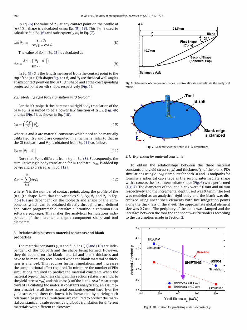
Fig. 6. Schematic of component shapes used to calibrate and validate the analyticalmodel.
along the thickness of the sheet. The approximate global elementsize was 0.7 mm. The periphery of the blank was clamped and theinterface between the tool and the sheet was frictionless accordingto the assumption made in Section 2.
90 D. Xu et al. / Journal of Manufa
In Eq. (6) the value of �OI at any contact point on the profile ofn + 1)th shape is calculated using Eq. (8) [18]. This �OI is used toalculate R in Eq. (6) and subsequently ϕ0 in Eq. (7).
an �OI = sin �1
L�x/� + cos �1(8)
The value of �x in Eq. (8) is calculated as
x =S sin
(∣∣�2 − �1
∣∣)sin �1
(9)
In Eq. (9), S is the length measured from the contact point to theop of the (n + 1)th shape (Fig. 4a). �2 and �1 are the ideal wall anglest any contact point on the (n + 1)th shape and at the correspondingrojected point on nth shape, respectively (Fig. 5).
.2. Modeling rigid body translation in IO toolpath
For the IO toolpath the incremental rigid body translation of thease ıIO is assumed to be a power law function of �y, L (Fig. 4b)nd �IO (Fig. 5), as shown in Eq. (10).
IO =(
�y
La
)�b
IO (10)
here, a and b are material constants which need to be manuallyalibrated, �y and L are computed in a manner similar to that inhe OI toolpath, and �IO is obtained from Eq. (11) as follows
IO =∣∣�2 − �1
∣∣ (11)
Note that �IO is different from �OI in Eq. (8). Subsequently, theumulative rigid body translation for IO toolpath, �IO, is added upy ıIO and expressed as in Eq. (12),
IO =N∑
i=1
(ıIO)i (12)
here, N is the number of contact points along the profile of then + 1)th shape. Note that the variables S, L, �y, �1 and �2 in Eqs.1)–(10) are dependent on the toolpath and shape of the com-onents, which can be obtained directly through a user-definedpplication programmable interface subroutine in common CADoftware packages. This makes the analytical formulations inde-endent of the incremental depth, component shape and tooliameters.
. Relationship between material constants and blankroperties
The material constants � , a and b in Eqs. (1) and (10) are inde-endent of the toolpath and the shape being formed. However,hey do depend on the blank material and blank thickness andave to be manually recalibrated when the blank material or thick-ess is changed. This requires further simulations and increaseshe computational effort required. To minimize the number of FEAimulations required to predict the material constants when theaterial type or thickness changes, this section relates � , a and b to
he yield stress (�y0) and thickness (t) of the blank. As a first attemptoward calculating the material constants analytically, an assump-ion is made that all these material constants depend linearly on the
ield stress and sheet thickness. It is shown that by deriving suchelationships just six simulations are required to predict the mate-ial constants and subsequently rigid body translation for differentaterials with different thicknesses.Fig. 7. Schematic of the setup in FEA simulations.
3.1. Expression for material constants
To obtain the relationships between the three materialconstants and yield stress (�y0) and thickness (t) of the blank, FEAsimulations using ABAQUS implicit for both OI and IO toolpaths forforming a spherical cap shape as the second intermediate shapewith a cone as the first intermediate shape (Fig. 6) were performed(Fig. 7). The diameters of tool and blank were 5.0 mm and 80 mmrespectively and the incremental depth used was 0.4 mm. The toolwas modeled as an analytical rigid body and the blank was dis-cretized using linear shell elements with five integration points
Fig. 8. Illustration for predicting material constant � .

D. Xu et al. / Journal of Manufacturing Processes 14 (2012) 487–494 491
Table 1Material properties used for calibrating the material constant � in OI toolpath andmaterial constants a and b in IO toolpath.
Material �y0 (MPa) t (mm) � a b
rv
rcbTdiTFtc
�
w
A
B
iadfitt
�
(c�
ebcs
w
dwcts
SS304 800 0.4 3.19 1.38 2.70SS304 800 1.0 2.30 1.44 2.90Ti6Al4V 469 0.4 4.24 1.25 3.25
The methodology of obtaining a relationship between the mate-ial constants and the blank properties will now be demonstratedia the example of expressing � as a function of �y0 and t.
Three FEA simulations were performed for two different mate-ials with two different thicknesses. The value of � was manuallyalibrated, as shown in Table 1, by matching predictions of rigidody translations from Eq. (1) with those from FEA predictions.o obtain such a relationship two linear assumptions were made ineriving the relationship between � , �y0 and t. The first assumption
s that the value of � changes linearly with �y0 when t is constant.he � values of SS304 and Ti6Al4V for t = 0.4 mm are plotted inig. 8 and these two points are connected by a straight line. Fromhe equation of this straight line the relationship between materialonstant � and �y0 at a constant t, is expressed as
(�y0) = (�y0 − B)A (13)
here
= (�tbaseline )material 1 − (�tbaseline )material 2(�y0)material 1 − (�y0)material 2
= (�y0)material 1 − 1A
(�tbaseline )material 1
This straight line is set as a baseline. The second assumptions that this baseline will vertically and linearly shift by a certainmount when sheet thickness changes. The shifting amount isetermined by the current sheet thickness t and a shifting coef-cient . Therefore, Eq. (13) is modified to Eq. (14) to take thishickness effect into account. Here tbaseline equals to 0.4 mm. Notehat, in contrast to the material constant � the shifting coefficient
is a constant that is independent of �y0 and t.
(�y0, t) =[(�y0 − B)A
]︸ ︷︷ ︸
Baseline
+ [(t − tbaseline)]︸ ︷︷ ︸Shifting amount
(14)
The manually calibrated value of � for SS304 with t = 1.0 mmTable 1) was used in Eq. (14) to calculate the value of the shiftingoefficient as −1.48. Now, Eq. (14) expresses the material constant
completely as a function of �y0 and t.For IO toolpath, the material constants a and b in Eq. (10) were
xpressed in a similar form. Therefore, a general equation cane used to express the relationship among these three materialonstants, the yield stress and thickness of the blank material ashown in Eq. (15).
= (�y0I − ˝)T + (t − tbaseline)� (15)
here
=
⎡⎣ �
a
b
⎤⎦ , ̋ =
⎡⎣ B 0 0
0 D 0
0 0 F
⎤⎦ , T =
⎡⎣ A
C
E
⎤⎦ , � =
⎡⎣
�
⎤⎦
A, B, C, D, E and F are represented by the material constantserived from FEA simulations and the corresponding yield stress
hen blank thickness is a constant and the values of theseoefficients are listed in Table 2. Only three more simulations forhe materials in Table 1 are required to calculate the correspondinghifting coefficients � and . In Eq. (15), tbaseline equals to 0.4 mm.
Fig. 9. Predictions using established relationship between material constants, yieldstress and sheet thickness for (a) material constant � (b) material constant a (c)material constant b.
492 D. Xu et al. / Journal of Manufacturing Processes 14 (2012) 487–494
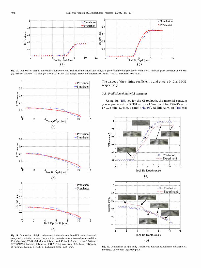
Fig. 10. Comparison of rigid body translation evolutions from FEA simulations and analyt(a) SS304 of thickness 1.5 mm: � = 1.57, max. error = 0.06 mm (b) Ti6Al4V of thickness 0.7
Fig. 11. Comparison of rigid body translation evolutions from FEA simulations andanalytical prediction models (the predicted material constants a and b are used) forIO toolpath (a) SS304 of thickness 1.5 mm: a = 1.49, b = 3.10, max. error = 0.046 mm(b) Ti6Al4V of thickness 1.0 mm: a = 1.31, b = 3.44, max. error = 0.049 mm (c) Ti6Al4Vof thickness 1.5 mm: a = 1.36, b = 3.61, max. error = 0.051 mm.
ical prediction models (the predicted material constant � are used) for OI toolpath5 mm: � = 3.73, max. error = 0.08 mm.
The values of the shifting coefficient � and were 0.10 and 0.33,respectively.
3.2. Prediction of material constants
Using Eq. (15), i.e., for the OI toolpath, the material constant� was predicted for SS304 with t = 1.5 mm and for Ti6Al4V witht = 0.75 mm, 1.0 mm, 1.5 mm (Fig. 9a). Additionally, Eq. (15) was
Fig. 12. Comparison of rigid body translations between experiment and analyticalmodel (a) OI toolpath (b) IO toolpath.

D. Xu et al. / Journal of Manufacturing Processes 14 (2012) 487–494 493
Fig. 13. Effects of yield stress and sheet thickness on the evolution of rigid body translation when (a) OI toolpath (b) IO toolpath is used.
Table 2Coefficient values for establishing the expression for material constants.
A (MPa−1) B (MPa) C (MPa−1) D (MPa) E (MPa−1) F (MPa) Shifting coefficient (mm−1)
uwc
ubicRlcf
fwmbosue
rtnb
4
ibsuwwt
−3.17E−3 1.81E3 3.93E−4 −2.71E3
sed to predict the values of a and b for the IO toolpath, for SS304ith t = 1.5 mm and for Ti6Al4V with t = 1.0 mm, 1.5 mm (Fig. 9b and
).For further validation, the predicted material constants were
sed in analytical formulations (Eqs. (1)–(12)) to predict the rigidody translations when forming the intermediate shapes as shown
n Fig. 6. These analytical predictions of rigid body translation wereompared to those obtained from FEA (Figs. 10 and 11, whereBTran stands for rigid body translation). Observe that these ana-
ytically predicted rigid body translations which use the materialonstant prediction formulations match well with those obtainedrom FEA.
Furthermore, simulations and experiments were performed toorm the same spherical cap geometry (Fig. 6) using AA5052 blankith 1.0 mm sheet thickness. In earlier work [16], the values ofaterial constants � , a and b for this case were manually calibrated
y trial and error to be 5.0, 1.0 and 4.0, correspondingly. The valuesf � , a, and b predicted by Eq. (15) were 4.86, 1.06 and 4.03, corre-pondingly. The analytically predicted rigid body translations thatsed predicted material constants matched well with those fromxperiments, as shown in Fig. 12.
Therefore, the developed relationships are able to predict mate-ial constants for blank with different yield stresses and sheethicknesses quite well. Additionally, only six FEA simulations areow needed to predict the material constants for any material andlank thickness.
. Discussion
In the case of the pure OI toolpath, the rigid body translationncreases with the sheet deformation (Fig. 13a). However, the rigidody translation saturates after a certain tool tip depth. The rea-on is that the accumulation of rigid body translation will make the
nformed region of the nth shape (r < rtool) gradually go downwardshen the (n + 1)th intermediate shape is being formed (Fig. 4a),hich eventually results in contact lost between the sheet and theool after this point during the forming process. In addition, the
�
−1.66E−3 2.42E3 −1.48 0.10 0.33
generated toolpath does not consider the influence of accumula-tion of rigid body translation and the tool still follows the idealtrajectory.
When only the IO toolpath is used, the rigid body translation ofthe base is slightly greater than zero at the beginning (Fig. 13b).This is because the tool indents into the sheet at the first point,which results in the Z depth of tool tip being greater than the Zdepth of the previous component base. Subsequently, the rigid bodytranslation keeps increasing with the tool movement in the positiveZ direction. Compared with the evolution of rigid body translationin OI toolpath, there is no saturation of rigid body translation sincecontact between the sheet and the tool is never lost. This is becausethe unformed region (r > rtool) in IO toolpath as shown in Fig. 4b isnot affected by rigid body translation.
Additionally, the rigid body translation reduces when yieldstress or sheet thickness increases. This is because the stiffnessof the unformed area is enhanced with the increased yield stressand sheet thickness. Furthermore, the rigid body translation pre-dictions can be in fact incorporated into the toolpath generationalgorithm for MSPIF to create a mixed toolpath (Fig. 3a) and thestepped feature generation was minimized as shown in Fig. 3b.
5. Conclusions
This paper enhances the previous work [16] by the authorson analytical prediction of stepped feature formation in MSPIF byreducing the number of prior FEA simulations required. In the priorwork, time-consuming finite element simulations are needed tobe performed every time when the material type or sheet thick-ness of the blank is changed. In this work, the three materialconstants used to predict the rigid body translation and subse-quent stepped feature formation are now related to the yield stressand the sheet thickness of the blank. It is shown that these pre-
dicted material constants can be used in the analytical model topredict the rigid body translation accurately. Since only six sim-ulations are required to establish these relationships for arbitrarymaterial types and thicknesses this methodology is a significant
4 cturing
aorbfmtn
A
Napt
R
[
[
[
[
[
[
[
[17] Yu TX, Zhang LC. Plastic bending: theory and applications. World Scientific;1996.
[18] Cui Z, Ren F, Xia ZC, Gao L. Deformation analysis of multi-stage incremental
94 D. Xu et al. / Journal of Manufa
ddition to the prior work. Furthermore, from a more physical pointf view, it is expected and observed that the rigid body translationeduces when the yield stress or sheet thickness increases sinceoth enhance the stiffness of the unformed region. Future work willocus on including the nonlinear effect of working materials on the
aterial constants � , a, and b. Furthermore, springback will needo be considered in toolpath generation algorithm, particularly, foron-conical shapes.
cknowledgments
The authors are grateful to the financial support from theational Science Foundation, USA, the Ministry of Education, Chinand the Chinese Scholarship Council. We also appreciate the sup-ort provided by the Indo-US Science and Technology Forum andhe Department of Science and Technology of India.
eferences
[1] Allwood JM, Shouler DR. Generalized forming limit diagrams showingincreased forming limits with non-planar stress states. International Journalof Plasticity 2009;25:1207–30.
[2] Allwood JM, Shouler DR, Tekkaya AE. The increased forming limits of incre-mental sheet forming process. Key Engineering Materials 2007;344:621–8.
[3] Malhotra R, Xue L, Belytschko T, Cao J. Mechanics of fracture in sin-gle point incremental forming. Journal of Materials Processing Technology2012;212:1573–90.
[4] Strano M. Technological representation of forming limits for negative incre-mental forming of thin aluminum sheets. Journal of Manufacturing Processes2005;7(2):122–9.
[5] Governale A, Franco AL, Panzeca A, Fratini L, Micari F. Incremental forming pro-
cess for the accomplishment of automotive details. Key Engineering Materials2007;344:559–66.[6] Jeswiet J, Micari F, Hirt G, Bramley A, Duflou A, Allwood J. Asymmetric sin-gle point incremental forming of sheet metal. CIRP Annals: ManufacturingTechnology 2005;54(2):623–49.
Processes 14 (2012) 487–494
[7] Ambrogio G, De Napoli L, Filice L, Gagliardi F, Muzzupappa M. Applica-tion of incremental forming process for high customized medical productmanufacturing. Journal of Materials Processing Technology 2005;162–163:156–62.
[8] Young D, Jeswiet J. Wall thickness variations in single-point incremental form-ing. Proceedings of the Institution of Mechanical Engineers, Part B: Journal ofEngineering Manufacture 2004;128:1453–9.
[9] Hussaiin G, Gao L. A novel method to test thinning limits of sheet metalsin negative incremental forming. International Journal of Machine Tools andManufacture 2007;47(3–4):419–35.
10] Attanasio A, Ceretti E, Giardini C. Optimization of tool path in twopoints incremental forming. Journal of Materials Processing Technology2006;177(1–3):409–12.
11] Malhotra R, Reddy NV, Cao J. Automatic 3D spiral toolpath generation for singlepoint incremental forming. Journal of Manufacturing Science and Engineering,Transactions of the American Society of Mechanical Engineers 2010;132(6),061003-1.
12] Kim TJ, Yang DY. Improvement of formability for the incremental sheetmetal forming process. International Journal of Mechanical Sciences2000;42(7):1271–86.
13] Hirt G, Ames J, Bambach M, Kopp R. Forming strategies and process modelingfor CNC incremental sheet forming. CIRP Annals: Manufacturing Technology2004;53(1):203–6.
14] Skjoedt M, Bay M, Endelt B, Ingarao G. Multi stage strategies for singlepoint incremental forming of a cup. International Journal of Material Forming2008;1(Suppl. 1):1199–202.
15] Duflou JR, Verbert J, Belkassem B, Gu J, Sol H, Henrard C, et al. Pro-cess window enhancement for single point incremental forming throughmulti-step toolpaths. CIRP Annals: Manufacturing Technology 2008;57(1):253–6.
16] Malhotra R, Bhattacharya A, Kumar A, Reddy NV, Cao J. A newmethodology for multi-pass single point incremental forming withmixed toolpaths. CIRP Annals: Manufacturing Technology 2011;60(1):323–6.
forming. Proceedings of the 2010 International Conference on ManufacturingScience and Engineering, 2010 [Paper No. 34040].