Embed Size (px)
Citation preview
Leonardo Electronic Journal of Practices and Technologies
ISSN 1583-1078
Issue 23 July-December 2013
p 63-82
Analytical Model of Underground Train Induced Vibrations on Nearby
Building Structures in Cameroon Assessment and Prediction
Lezin Seba MINSILI1 He XIA2 and Robert Medjo EKO3
1 LMMC-GC National Polytechnic Advanced School The University of Yaoundeacute I Cameroon
2 School of Civil Engineering amp Architecture Beijing Jiaotong University Beijing China 3 Department of Earth Science Faculty of Science The University of Yaounde I Cameroon
E-mails lezinsmyahoocom hxia88163com rmedjoyahoocom Corresponding author Phone +237-77922659
Abstract
The purpose of this research paper was to assess and predict the effect of
vibrations induced by an underground railway on nearby-existing buildings
prior to the construction of projected new railway lines of the National
Railway Master Plan of Cameroon and after upgrading of the railway
conceded to CAMRAIL linking the two most densely populated cities of
Cameroon Douala and Yaoundeacute With the source-transmitter-receiver
mathematical model as the train-soil-structure interaction model taking into
account sub-model parameters such as type of the train-railway system
typical geotechnical conditions of the ground and the sensitivity of the nearby
buildings the analysis is carried out over the entire system using the dynamic
finite element method in the time domain This subdivision of the model is a
powerful tool that allows to consider different alternatives of sub-models with
different characteristics and thus to determine any critical excessive vibration
impact Based on semi-empirical analytical results obtained from presented
models the present work assesses and predicts characteristics of traffic-
induced vibrations as a function of time duration intensity and vehicle speed
as well as their influence on buildings at different levels
Keywords
Railway Train Track Vibration Building Dynamic load Sub-model
Acceleration
63 httplejptacademicdirectorg
Analytical Model of Underground Train Induced Vibrations on Nearby Building Structures in Cameroon Assessment and Prediction
Lezin S MINSILI He XIA and Robert M EKO
Introduction
In 2008 the Cameroon government announced its long-term vision for vitalizing the
economy and developing the nation into a newly industrialized country by the year of 2035
Among a number of strategies devised to bolster the industry the need to expand transport
infrastructures which constitute a major hindrance in its economic progress despite a rich
reserve of mineral resources such as diamonds iron and bauxite Research conducted by
international organizations such as the World Bank or the United Nations [1] also concludes
that the railway network must be modified and renewed for Cameroonrsquos economic
development Cameroon government must lose no time in reforming the railway network in
order to maximize the countryrsquos potentials as the overall backwardness of the national
economy is undermining the effectuality of Cameroonrsquos rich mineral resources As a result
the Cameroon government requested a Korean Consortium KORPEC to conduct a
prefeasibility study leading to the establishment of a National Railway Master Plan (NRMP)
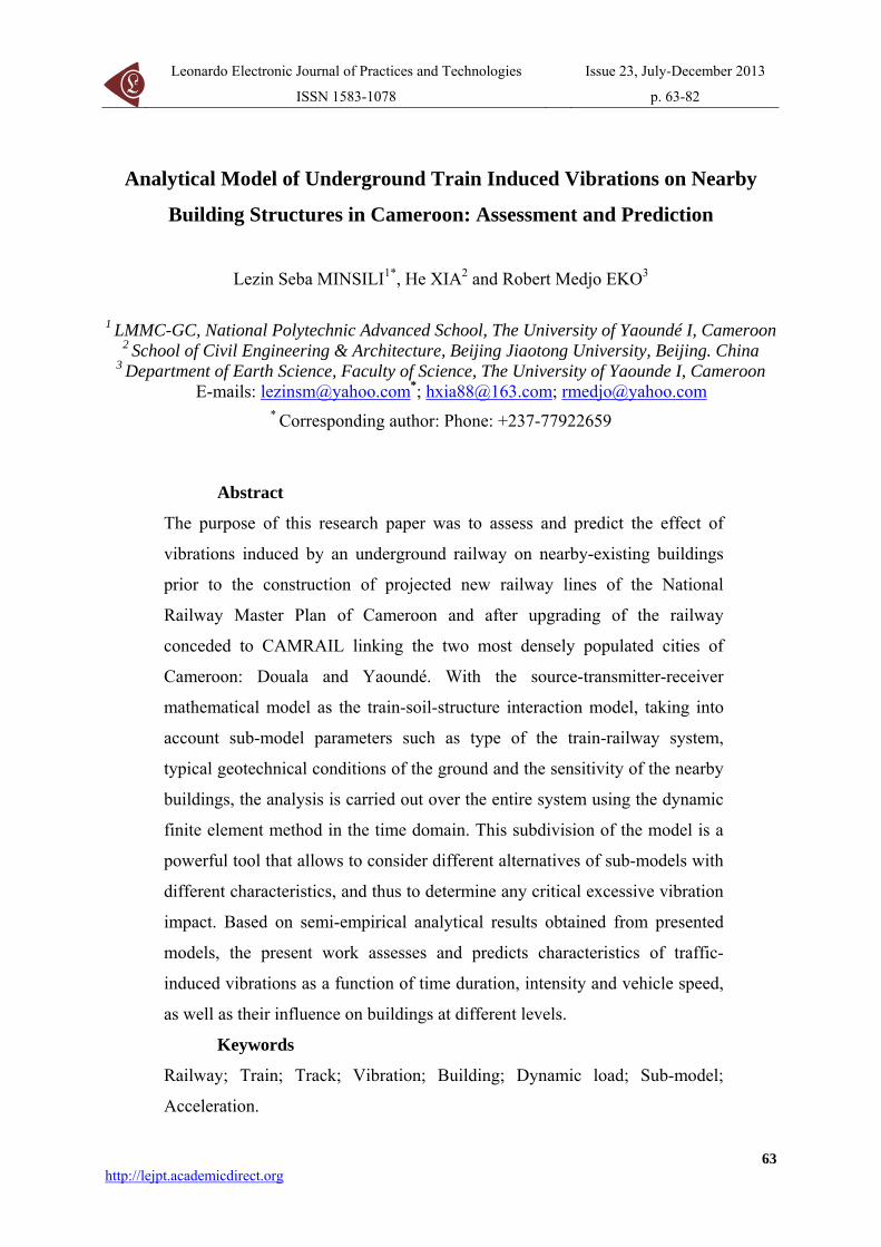
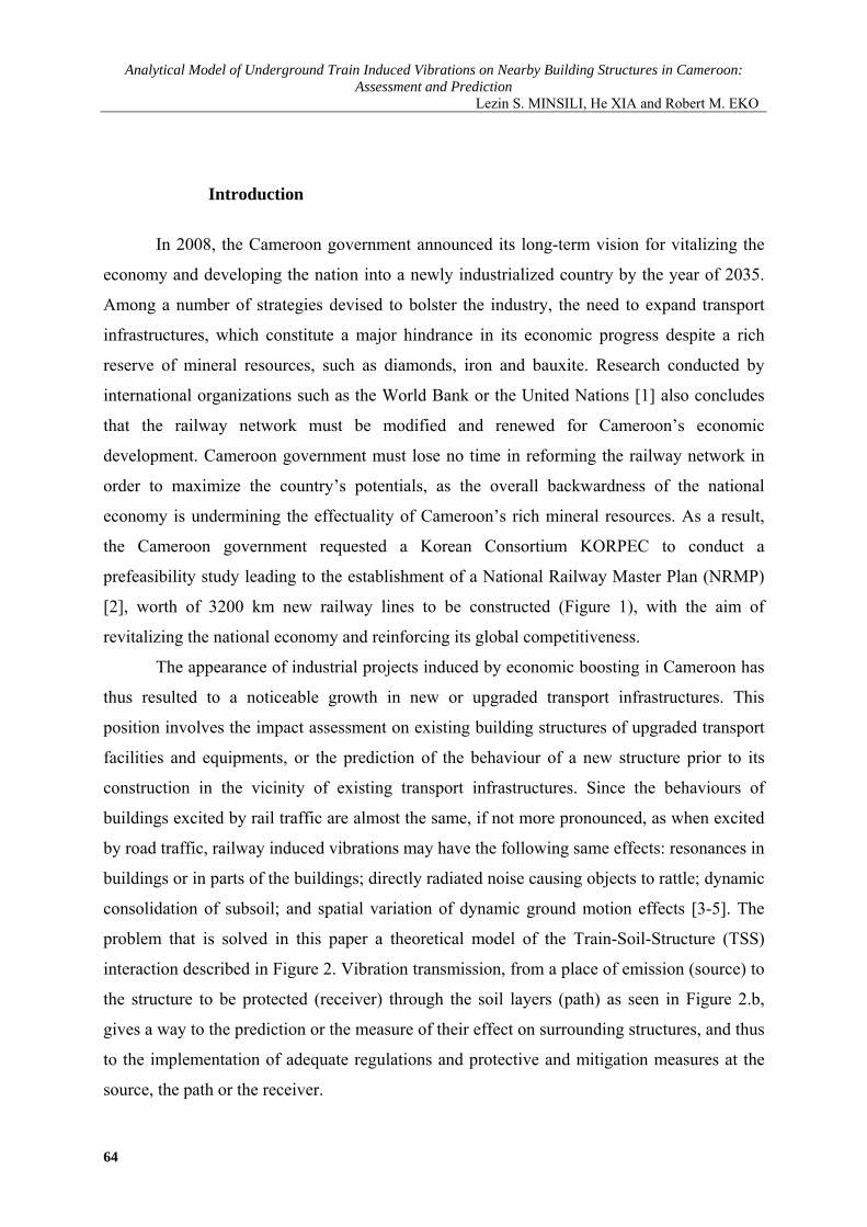
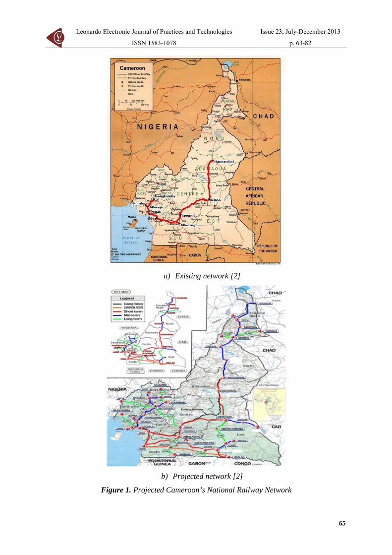
[2] worth of 3200 km new railway lines to be constructed (Figure 1) with the aim of
revitalizing the national economy and reinforcing its global competitiveness
The appearance of industrial projects induced by economic boosting in Cameroon has
thus resulted to a noticeable growth in new or upgraded transport infrastructures This
position involves the impact assessment on existing building structures of upgraded transport
facilities and equipments or the prediction of the behaviour of a new structure prior to its
construction in the vicinity of existing transport infrastructures Since the behaviours of
buildings excited by rail traffic are almost the same if not more pronounced as when excited
by road traffic railway induced vibrations may have the following same effects resonances in
buildings or in parts of the buildings directly radiated noise causing objects to rattle dynamic
consolidation of subsoil and spatial variation of dynamic ground motion effects [3-5] The
problem that is solved in this paper a theoretical model of the Train-Soil-Structure (TSS)
interaction described in Figure 2 Vibration transmission from a place of emission (source) to
the structure to be protected (receiver) through the soil layers (path) as seen in Figure 2b
gives a way to the prediction or the measure of their effect on surrounding structures and thus
to the implementation of adequate regulations and protective and mitigation measures at the
source the path or the receiver
64
Leonardo Electronic Journal of Practices and Technologies
ISSN 1583-1078
Issue 23 July-December 2013
p 63-82
a) Existing network [2]
b) Projected network [2]
Figure 1 Projected Cameroonrsquos National Railway Network
65
Analytical Model of Underground Train Induced Vibrations on Nearby Building Structures in Cameroon Assessment and Prediction
Lezin S MINSILI He XIA and Robert M EKO
a) An abandoned 18-floor story building b) Model of the TSS interaction
Figure 2 Graphical description of the TSS interaction
The aim of the research was to implement in Cameroon a sound expertise and a lasting
experience in making predictions about ground-borne vibration The model adopted in this
work was used by Xia He [6] which has been presented in form of an equation containing the
needed parameters to be used for different types of trains on different soil conditions The
geometry of the model and its parameters are chosen so that the most important aspects of the
issue are considered without making the model too complicated or impractical [7] Numerical
results obtained from the model in the vertical plane allows to predict accelerations as the
main vibration characteristics at any location from the railway track and at any floor level of
the structure taken as an 18-story unused building located above the vicinity of a railway
tunnel as seen in Figure 2
Dynamic Load of Metro Train
Analytical Model of Metro Train-Track-Tunnel System
The train track system receives the load from the wheels and then transfers it to the
substructure The load includes two parts the vertical moving constant load (ie axle load)
and the dynamic load produced by wheel-rail contact To simplify the analytical model the
following hypotheses are made
66
Leonardo Electronic Journal of Practices and Technologies
ISSN 1583-1078
Issue 23 July-December 2013
p 63-82
(1) Because the vertical excitation applied to the substructure by the running train is much
larger than the horizontal excitation the analysis is carried through only in the vertical plane
(2) The rail is simulated as a continuous Euler-Bernoulli beam
(3) The wheel-rail interaction is obtained by using the Hertzian contact theory in which the
Hertzian contact coefficient is expressed as kH
(4) For simplicity the irregularity curve is thought of as a sine wave profile
)]lx2cos(1[
2a)x(w0 πminusminus=
(1)
where w0(x) = the rail irregularity profile at the position of x a = the maximum amplitude of
rail irregularity and l = its wavelength
(5) Because the effective length of the rail deflection is usually much larger than the sleeper
distance the periodic support of sleepers to rails is reasonably neglected in this model [8]
though in fact the rails are supported by a series of sleepers with equal space
(6) The coupling between the track and the tunnel structure is simulated by springs The
spring stiffness ks are called the distributed track spring stiffness [9-10] whose value is equal
to the support stiffness of the rails divided by the sleeper distance And the support stiffness
of the rails is expressed by the series-wound stiffness of the rail fastener stiffness elastic pads
stiffness sleeper stiffness and roadbed-tunnel liner stiffness
According to the above assumptions the analytical model of metro train-track-tunnel
system is established as is shown in figure 3
Rail Dynamic Deflection Induced by Single Wheel
Since the load applied to the rail is moving along x axle with the train speed v the rail
deflection curve cannot be static but a kind of dynamic deflection curve like a wave moving
along x axle with the speed v as is showed in figure 3(b) In this model N specifies the total
number of the wheels Tn and xn are respectively the constant load amplitude and its initial
position of the n-th wheel Based on the theory of Euler-Bernoulli beam the rail dynamic
deflection w(xt) induced by single wheel is governed by the following partial differential
equation
)vtxx()]tx(PT[ wktwm
xwEI nnns2
2
04
4
minusminusδ+=+partpart
+partpart
(2)
where EI = the rail bending stiffness and m0 = the rail mass per unit length (sleepers
67
Analytical Model of Underground Train Induced Vibrations on Nearby Building Structures in Cameroon Assessment and Prediction
Lezin S MINSILI He XIA and Robert M EKO
included) x = the horizontal distance of the constant load Tn = away from coordinate origin
during the process of moving and Pn(xt) = the dynamic contact force between wheel and rail
[11]
a) Geometrical parameters of train and track
(b) Interaction model of metro train-track-tunnel
Figure 3 Analytical model of metro train-track-tunnel system
The initial condition is
0|tw|)tx(w 0t0t =partpart
= == (3)
Also the boundary condition at the infinity is
68
Leonardo Electronic Journal of Practices and Technologies
ISSN 1583-1078
Issue 23 July-December 2013
p 63-82
)3210n(0x
)tx(wlim n
n
x==
partpart
plusmninfinrarr
(4)
Firstly the rail static deflection curve is expressed When the train is static the load
applied to the rail is static constant axle load Tn Correspondingly the rail deformation is
described as a static deflection curve [12-13]
s
0|x|3
nst
kgm|)]x|sin()x[cos(e
EI8Tw +β+βsdottimesβ
= βminus (5)
where the superscript st denotes the static solution and It can be seen from
this equation that the effective length of rail deflection curve is
41s )EI4k(=β
βπ= xst0
Equation (2) shows that the dynamic deflection is induced by two kinds of loads the
moving constant load and the moving dynamic load The solution thus consists of two parts
corresponding to the two loads
For the moving constant load )vtxx(T nn minusminusδ based on Equation (5) the dynamic
deflection curve can be easily expressed as follows
|)]vtxx|sin())vtxx([cos(e]EI8T[)tvtxx(w nn|vtxx|3
nn1n minusminusβη
ηδ
+minusminusβηsdottimesδβ=minusminus minusminusβδminus (6)
where 2min )cv(1minus=δ and 2
min )cv(1+=η with the velocity of
free track waves
4120smin )mEIk4(c =
For the moving dynamic load )vtxx()tx(P nn minusminusδ the Green function of the rail
dynamic deflection induced by unit impulse load is introduced first The dynamic deflection
of the rail under unit impulse load is
)vtxx()tx(Pwkxwm
xwEI nδs2
2
04
4
minusminusδ=+partpart
+partpart
(7)
By using the Laplace transformation Fourier transformation and their corresponding
inverse transformations the final solution of the Green function Equation (7) can be solved
as
ωsdotβminusω
sdotβminusωααπ
= ωinfin+
int de4
)t4sin(m1)tx(G xi
0 44
44
(8)
where mEI=α and 41s )EI4k(=β
69
Analytical Model of Underground Train Induced Vibrations on Nearby Building Structures in Cameroon Assessment and Prediction
Lezin S MINSILI He XIA and Robert M EKO
Based on the generalized Duhamel integral the rail dynamic deflection curve under
the moving dynamic load )vtxx()tx(P nn minusminusδ can be expressed as
ωτsdotβminusω
τminussdotβminusωαtimesτminusminus
απ=
=lowast=minusminus
minusminusωinfin+
int int dde4
)]t(4sin[)vtxx(Pm1
)tx(P)tx(G)tvtxx(w
)vtxx(i
44
44t
0 0 n
n2
n
(9)
Therefore the total dynamic deflection of the rail is the summation of the above two
deflections
)tvtxx(w)tvtxx(w)tvtxx(w n2n1n minusminus+minusminus=minusminus (10)
Since the load applied to rail is moving along x axle with the speed v by introducing
the local coordinate system xloc = x-xn-vt the dynamic deflection of the rail induced by single
wheel can be expressed as
)tx(w)tx(w)tx(w loc2loc1ocl += (11)
where
|)]x|sin()x[cos(e]EI8T[)tx(w locloc|x|3
nloc1loc βη
ηδ
+βηtimestimesδβ= βδminus (12)
ωτsdotβminusω
τminussdotβminusωαtimesτ
απ= ωinfin+
int int dde4
)]t(4sin[)x(Pm1)tx(w locxi
44
44t
0 0 locloc2 (13)
Dynamic Load Applied onto Tunnel
As shown in figure 3(b) the downward force transferred onto the tunnel from each
sleeper equals to the upward spring force bore on this sleeper width expressed as
f(t)=ksΔdw(xloc) herein Δd is the sleeper width and its acting point lies under the sleeper
On the other hand it is not all sleepers but a certain number of sleepers at the range of the
deflection curve effective length that are involved in the distribution of this force endured by
the rail These involved sleepers are called the effective sleepers and if Neff denotes the
number of effective sleepers it can be seen from the model figure that d2xN st0eff asymp
In order to eliminate Δd from the expression of f(t) the rail static deflection equation
(7) is integrated along x in which the influence of m0g is neglected considering that m0g is
much smaller than Tn Due to the non-continuous support of actual sleepers the integral can
be written as the summation of Neff integrals and so there is the expression of
70
Leonardo Electronic Journal of Practices and Technologies
ISSN 1583-1078
Issue 23 July-December 2013
p 63-82
)t(PTdNΔwk nneffstmaxs += The substitution of it into f (t) results in
stmax
loc
eff
nn
w)x(w
N)t(PT)t(f +
= (14)
If gn(xloct) is used to denote the dynamic load at the point of xloc applied onto tunnel
by the n-th wheel the following solution can be obtained by all the above derivations
)xvtxx()idx(w
)x(wN
)t(PT)tx(g nlocstmax
loc
eff
nnlocn minus++δminusδ
+=
(15)
where δ function is introduced to explain that the acting point of this force is below under the
sleeper n = the serial number of the wheel and i = the serial number of the sleeper
corresponding to the force position
The final dynamic force F(xt) applied onto the tunnel by all the N wheels can be
obtained by means of the superposition principle (the original coordinate system is reverted)
)tx(g)vtxxx()idx()tx(F locnn
N
1nloc minusminusminusδminusδ=sum
=
(16)
Substitute Equation (15) into Equation (16) the following expression can be obtained
stmax
nN
1n eff
nn
w)vtxx(w
N)t(PT)idx()tx(F minusminus+
minusδ= sum=
(17)
Discrete Dynamic Model of the System
Ground-born vibrations are the result of the train-track structure exciting the tunnel
and adjacent soil layers and creating waves that propagate to the foundations of nearby
buildings These received vibrations at the foundation propagate throughout other parts of the
building structure [14-19] are showing that the ground-borne vibration due to wheel-tract
trains is function of the geology condition the covering depth the train-track system Since
the response from this vibration input depends on building structural characteristics the
dynamic model is subdivided into different sub-models the train model the track model and
the building model
The train model is composed by a series of wagons each consisting of car body
bogies wheel sets springs and dashpots To simplify to analysis the following hypotheses
71
Analytical Model of Underground Train Induced Vibrations on Nearby Building Structures in Cameroon Assessment and Prediction
Lezin S MINSILI He XIA and Robert M EKO
developed by Xia [20] are made on the vehicle (1) car bodies bogie frame and wheel sets are
rigid without elastic deformation (2) all dampers are viscous (3) lateral movements and
vertical movements of the vehicles are not coupled with each other Thus there are two
degrees of freedom (DOF) (floating and nodding) for each car body and bogie represented by
Zc φc and ZT φT respectively and one DOF for each wheel set (floating Zw) The total DOF
number for a 4-axle train vehicle therefore is ten
The track model consists of rail and rubber pads as seen in figure 4 The assumptions
for the track model are (1) the rail is taken as an endless beam on elastic supports its mass
and stiffness matrix in the dynamic equations while the damping matrix is formed by the
assumption of Rayleigh damping (2) the stiffness and damping of the pads and fasteners are
simplified into a set of compound masses springs and dampers represented by mi ki and ci
respectively (3) The analysis is carried out only in the vertical plane According to these
assumptions there are 2 DOFs (vertical displacement and rotation) for each rail node and one
DOF (vertical movement) for each mass in the elastic support The total number of DOF of
the system therefore is 2N+2n where N is the number of rail nodes and n is the number of
elastic supports sets
Figure 4 Dynamic model of Train-track system
From the assumptions made above the FE dynamic equilibrium equations of the train
and the rail track is assembled into a single relation and the global equilibrium equation of
72
Leonardo Electronic Journal of Practices and Technologies
ISSN 1583-1078
Issue 23 July-December 2013
p 63-82
the train-rail track system is obtained as
)tx(FKZZCZM =++ (18)
Or in matrix form
⎪⎪⎭
⎪⎪⎬
⎫
⎪⎪⎩
⎪⎪⎨
⎧
=
⎪⎪⎭
⎪⎪⎬
⎫
⎪⎪⎩
⎪⎪⎨
⎧
⎥⎥⎥⎥
⎦
⎤
⎢⎢⎢⎢
⎣
⎡
+
⎪⎪⎭
⎪⎪⎬
⎫
⎪⎪⎩
⎪⎪⎨
⎧
⎥⎥⎥⎥
⎦
⎤
⎢⎢⎢⎢
⎣
⎡
+
⎪⎪⎭
⎪⎪⎬
⎫
⎪⎪⎩
⎪⎪⎨
⎧
⎥⎥⎥⎥
⎦
⎤
⎢⎢⎢⎢
⎣
⎡
n
2
1
n
2
1
n
2
1
n
2
1
n
2
1
n
2
1
n
2
1
F
FF
Z
ZZ
K00
0K000K
Z
ZZ
C00
0C000C
Z
ZZ
M00
0M000M
(19)
Where the wheel-rail contact force F(xt) is calculated using the Hertzian contact
theory by using the discrete form of the Train-rail track interaction along the rail axis given
as
[ ]sum δminusminusφ=k
51ijijwijHlijl )x()tx(vZkF (20)
where Zwj(t) = the wheel displacement v(xt) = the rail deflection at the wheel-rail contact
point δ(x) = the wheel or rail profile change kH = the Hertzian contact coefficient n = the
number of vehicles Mi = the mass matrix of the i-th vehicle (being a diagonal matrix we have
Diag Mi=[Mc Jc MT1 MT2 JT2 Mw1 hellip Mw4]) Ki = the vehicle stiffness matrix and Ci =
the damping matrix Zi is the vehicle displacement vector Fi is the force vector of the i-th
vehicle Mn Cn Kn are respectively the mass damping and the stiffness matrices of the track
are respectively the nodal acceleration velocity and displacement vectors as
given in the FE dynamic equation oslashij is the distributive coefficient of the j-th wheel-set to the
i-th rail node
vandvv
Simulation and Analysis of the TSS Interaction
Simulation by the FEM
The FEM is the most widely used numerical method implemented by researchers and
commercial software producers It can be used to solve complex geometries but it requires an
appropriate discrete form of the media being modelled This makes the FEM computationally
unfeasible for very large scale models such as those involving unbounded domains unless
substantial shortcuts are implemented These may entail the use of coarse elements low
frequency simulations or the introduction of boundary artefacts [21] This not being the case
73
Analytical Model of Underground Train Induced Vibrations on Nearby Building Structures in Cameroon Assessment and Prediction
Lezin S MINSILI He XIA and Robert M EKO
of the present work since the soil sub domain and the building sub domain are bounded with
appropriate boundary conditions as seen in the FE element model of the tunnel-soil-building
system shown in figure 5 assuming a 2-D plane strain state The double-track is inside the
single hollow tunnel with a dimension of 10m (height) times12m (width) and with 14m cover
depth The soil is divided into four layers with their parameters shown in Table 1 An 18-
story building is set at 30m from the tunnel centreline which has the pile foundation with
15m length and whose members are all simulated as beam elements
Figure 5 Finite element model of tunnel-soil-building system
Table 1 Parameters of the building and sub soils Materials Elastic modulus
[MPa] Poisson ratio Density
[Nmiddotm-3]Remarks
C30 Concrete 30000 018 2550 Beam (03mtimes06m) Columns (06mtimes06m)
Backfilling soil 29 040 17000 Arenaceous clay 1 127 033 18800 Moderate fine sand 136 037 20200 Arenaceous clay 2 77 028 20000
74
Leonardo Electronic Journal of Practices and Technologies
ISSN 1583-1078
Issue 23 July-December 2013
p 63-82
The vibration evaluation method is settled in accordance with ISO26311-1985 that
adopts the vertical acceleration level in terms of Lz=20log10(aa0) where a is transient
acceleration of the observation points with the unit of ms2 and a0 is the basic acceleration
with the value of 1times10-5ms2 Since the model is asymmetric the whole system must be
analyzed and the FE model should be as large as possible to contain the train length and to
reduce the effect of the wave reflection at the artificial border In this analysis the model
covers a dimension of 650mtimes80m The bottom is assumed to have fixed constraints and the
two sides are spring elements with the stiffness of 500kNm
The damping behaviour of each basic component j of the rail track-ground system was
modelled using the Rayleigh method The damping matrix C can be obtained from the
relation
KMC jjjj βα += (21)
where Mj and Kj are the j-th components of the mass and the stiffness matrices (respectively)
Determination of the parameters αj and βj (as example αj =004 and βj =001) was carried out
using the procedure described by Di Mino [22]
A train composed of 6 cars running on a track of continuous welded rails of 50 kgm is
considered The mass of concrete sleeper is 251 kg and the sleeper space is d=055m The
distributed rail spring stiffness is ks=20246 MNm2 and the wheel-rail contact stiffness
coefficient is kH=1421MNm Implementing the theory and model described above with the
vehicle and track parameters listed in table 2 the dynamic loads applied to the tunnel is
obtained as shown in figure 6
Table 2 Calculation parameters of underground vehicle Vehicle full length L(m) 1952Bogie centrelinesrsquo distance 2s(m) 1266Fixed axle spacing 2d(m) 230 Car body mass Mc(t) 37 Car mass moment of inertia Jc (t-m2) 1700 Bogie mass Mt(t) 360 Bogie mass moment of inertia Jt(t-m2) 962 Bogie spring stiffness Kt (kNm) 2080 Bogie damping coefficient Ct (kNsm) 240 Wheel set mass Mw (t) 170 Wheel spring stiffness (kNm) 2450 Wheel damping coefficient Kw (kNsm) 240
75
Analytical Model of Underground Train Induced Vibrations on Nearby Building Structures in Cameroon Assessment and Prediction
Lezin S MINSILI He XIA and Robert M EKO
a) Dynamic load of train-track system
b) The spectrum of the train-track dynamic load
Figure 6 Characteristics of the dynamic load applied to the tunnel
Analytical Results
The previous figures describe the calculated dynamic load and its frequency spectrum
when the train speed is 50 kmh which clearly show that the force is mainly induced by the
moving axle loads of vehicles and that the load mainly concentrates at the frequency range of
0 to 10Hz This load is adopted as the dynamic load for the next calculation
Figure 7 shows the distribution of ground vibrations at two locations perpendicular to
76
Leonardo Electronic Journal of Practices and Technologies
ISSN 1583-1078
Issue 23 July-December 2013
p 63-82
the tunnel centreline It can be seen that the maximum acceleration within the distance of 30m
(49cms2) is smaller than the maximum level at 0 m (81cms2) The difference between
computed acceleration time histories computed at these locations is due to the vibration
attenuation with distance This attenuation of the peak acceleration from 81 to 49 might be
dependent on the train speed and train loading the geotechnical conditions of the soil and
possibly to the frequency components of the train-track excitation loading that is filtered
throughout soil layers
a) at 0 m from the tunnel centreline
b) at 30 m from the tunnel centreline
Figure 7 Ground acceleration time histories
77
Analytical Model of Underground Train Induced Vibrations on Nearby Building Structures in Cameroon Assessment and Prediction
Lezin S MINSILI He XIA and Robert M EKO
The train still running at the speed of 50kmh the building acceleration time-histories
of the first floor the 8th floor and the top floor are illustrated in figure 8 It can be seen that
the form of acceleration amplitude changes at different floor With the present vibration
amplification of the maximal acceleration response from the first floor to the top floor level it
is obvious that the building structure generates energy with time increment what is easily
noticed at the first floor level in figure 8a
a) at the first floor
b) at the 8-th floor
Figure 8 The acceleration time history at different floor levels
78
Leonardo Electronic Journal of Practices and Technologies
ISSN 1583-1078
Issue 23 July-December 2013
p 63-82
c) at the top level
Figure 8 The acceleration time history at different floor levels
Many investigations support that in a structure under specific modal vibration some of
its parts or elements can be subjected to local resonance and even self-excitation Thus the
observed acceleration amplification from the 3-rd second in figure 8c is related to local
resonance From literature survey [16-17 23-26] it is known that there are no damages on a
building due to train induced ground-borne vibration even if human occupants of the
buildings might be seriously affected But the computed results from the given model shows
that there is the possibility for an underground train passing through an urban area under
specific sub-models described above to excite a particular building or some of its elements
with one of their natural frequencies thus creating the resonance problem Investigations on
this problem are still going on in the Department
Conclusions
The TSS presented in this paper is subdivided into three main sub-models the source
the propagation path and the receiver in order to study and understand the influence of factors
such as dynamic characteristics of the train the railway structure soil and building
characteristics on ground-born vibrations and their effects on nearby building structures
By dividing the TSS model into sub-models it is possible to replace some parts of the
model with data from a particular site if available Thus if a new railway is being designed
79
Analytical Model of Underground Train Induced Vibrations on Nearby Building Structures in Cameroon Assessment and Prediction
Lezin S MINSILI He XIA and Robert M EKO
close to a building a prediction with good accuracy can be made on the effects of the
anticipated railway on the building
With the limitations of available data on TSS interaction in Cameroon experiments
and measurements are still to be done at sites with different geotechnical conditions different
train-track models and different building types to validate obtained results and thus elucidate
these important facts
Acknowledgements
This paper is a continuation of the study presented at the ldquo3rd International Symposium
on Environmental Vibrations Prediction Monitoring Mitigation and Evaluationrdquo 2007
References
1 The World Bank Cameroon Upgrading Low Income Urban Settlements - Country
Assessment Report 2002 AFTU 1 amp 2 Available at
httpwebmiteduurbanupgradingupgradingcase-examplesoverview-africacountry-
assessmentsdownloadCAMEROONpdf (accessed 08062013)
2 NRMP The National Railway Network Master Plan in Cameroon Final report of the
prefeasibility study conducted by KORPEC (KORea Port Engineering Corporation) and
Validated by the Government of Cameroon 2012 p 390-402
3 Du XT Xu Y L Xia H Dynamic interaction of bridgendashtrain system under non-
uniform seismic ground motion Earthquake Engineering Structural Dynamics 2012
41 p 139-157 DOI 101002eqe1122
4 Rodriacuteguez-Tembleque L Abascal R A 3D FEMndashBEM Rolling Contact Formulation
for Unstructured Meshes International Journal of Solids and Structures 2010 47 p
330-353 Available at
httpwwwsciencedirectcomsciencearticlepiiS0020768309003953 (accessed
08062013)
5 Zolghadr Jahromi H Izzuddin BA Zdravkovic L Partitioned analysis of nonlinear
80
Leonardo Electronic Journal of Practices and Technologies
ISSN 1583-1078
Issue 23 July-December 2013
p 63-82
soil-structure interaction using iterative coupling Interaction and Multiscale
Mechanics 2007 1(1) p 33-51
6 Xia H Dynamic Interaction of Vehicles and Structures Science Press Beijing China
2002
7 Chore HS Ingle RK Sawant VA Building frame - pile foundation - soil interaction
analysis a parametric study Interaction and Multiscale Mechanics 2010 3(1) p 55-
79
8 Krylov VV Effects of track properties on ground vibrations generated by high-speed
trains ACUSTICA-Acta Acustica 1998 84(1) p 78-90
9 Daumueller AN Jauregui DV Strain-Based Evaluation of a Steel Through-Girder
Railroad Bridge Hindawi Publishing Corporation Advances in Civil Engineering
2012 Available at httpwwwhindawicomjournalsamseai(accessed 17062013)
10 Xiaoyan L Numerical Analysis of Track Structures in Railway Beijing China Railway
Press 1998
11 Grassie SL Gregory RW Dynamic response of railway track to high frequency
vertical excitation Journal of Mechanical Engineering Science 1982 24(2) p 77-90
12 Flyacuteba L Vibration of Solids and Structures Under Moving Loads London Thomas
Telford 1999
13 Weitsman Y On foundations that react in compression only Journal of Applied
Mechanics 1970 12 p 1019-1030
14 Wang K Liu P Lateral Stability Analysis of Heavy-Haul Vehicle on Curved Track
Based on WheelRail Coupled Dynamics Journal of Transportation Technologies 2012
2(2) p 150-157 Available at httpwwwSciRPorgjournaljtts (accessed 08062013)
15 Woods RD Screening of Surface Waves in Soils Journal of Soil Mechanics and
Foundation Division Proceedings of the ASCE 1968
16 Woods RD Larry PJ Energy-Attenuation Relationships from Construction
Vibrations Vibration Problems in Geotechnical Engineering ASCE Proceedings
Detroit Michigan 1985
17 Eisenman J Deischl F Structure-Borne Sound from Underground Railway Systems
81
Analytical Model of Underground Train Induced Vibrations on Nearby Building Structures in Cameroon Assessment and Prediction
Lezin S MINSILI He XIA and Robert M EKO
82
Der Eisenbahningenieur 1986 3 p 101-110
18 Alshawi M Underwood J Improving the constructability of design solutions through
an integrated system Journal of Engineering Construction and Architectural
Management 1993 3(1amp2) p 47ndash67 doi101108eb021022
19 Patrick C Low Vibration and Noise Track Systems with Tunable Properties for Modern
LRTStreetcar Track on Surface in Urban Areas TIVCrsquo2001 International Symposium
on Traffic Induced Vibrations amp Controls Beijing China 2001 p 161-176
20 Xia H Cao YM Zhang N Numerical Analysis of Vibration Effects of Metro Trains
on Surrounding Environment Int J of Structural Stability and Dynamics 2007 7 p
45-56
21 Le Kouby A Bourgeois E Rocher-Lacoste F Subgrade Improvement Method for
Existing Railway Lines ndash an Experimental and Numerical Study Electronic Journal of
Geotechnical Engineering 2010 15 p461-494
22 Di Mino G Di Liberto CM Nigrelli J A FEM model of rail track-ground system to
calculate the ground borne vibrations a case of rail track with wooden sleepers and k-
fastenings at Castelvetrano Advanced Characterisation of Pavement and Soil
Engineering Materials Athens Greece 2007 p 1737-1752
23 Chauhan HM Pomal MM Bhuta GN A Comparative Study Of Wind Forces On
High-Rise Buildings as Per Is 875-Iii (1987) and Proposed Draft Code (2011) GRA -
Global Research Analysis 2013 2(5) p 59-60
24 Lei X Zhang B Influence of track stiffness distribution on vehicle and track
interactions in track transition Proceedings of the Institution of Mechanical Engineers
Part F Journal of Rail and Rapid Transit 2010 224592 p 592-604 Available at
httppifsagepubcomcontent2246592 (accessed 28082012)
25 Thorat YV Kadam SS Design and Development of Test Setup for VibrationAnalysis
with Soft Foot Indian Journal of Applied Research 2012 2(3) p 59-62
26 Xiaojing Sun Weining Liu Dawen Xie Yingxuan Jia Vibration impacts on adjacent
sensitive buildings induced by metro trains World Tunnel Congress 2008 -
Underground Facilities for Better Environment and Safety ndash India Agra 2008 p 1382-
1389
Analytical Model of Underground Train Induced Vibrations on Nearby Building Structures in Cameroon Assessment and Prediction
Lezin S MINSILI He XIA and Robert M EKO
Introduction
In 2008 the Cameroon government announced its long-term vision for vitalizing the
economy and developing the nation into a newly industrialized country by the year of 2035
Among a number of strategies devised to bolster the industry the need to expand transport
infrastructures which constitute a major hindrance in its economic progress despite a rich
reserve of mineral resources such as diamonds iron and bauxite Research conducted by
international organizations such as the World Bank or the United Nations [1] also concludes
that the railway network must be modified and renewed for Cameroonrsquos economic
development Cameroon government must lose no time in reforming the railway network in
order to maximize the countryrsquos potentials as the overall backwardness of the national
economy is undermining the effectuality of Cameroonrsquos rich mineral resources As a result
the Cameroon government requested a Korean Consortium KORPEC to conduct a
prefeasibility study leading to the establishment of a National Railway Master Plan (NRMP)
[2] worth of 3200 km new railway lines to be constructed (Figure 1) with the aim of
revitalizing the national economy and reinforcing its global competitiveness
The appearance of industrial projects induced by economic boosting in Cameroon has
thus resulted to a noticeable growth in new or upgraded transport infrastructures This
position involves the impact assessment on existing building structures of upgraded transport
facilities and equipments or the prediction of the behaviour of a new structure prior to its
construction in the vicinity of existing transport infrastructures Since the behaviours of
buildings excited by rail traffic are almost the same if not more pronounced as when excited
by road traffic railway induced vibrations may have the following same effects resonances in
buildings or in parts of the buildings directly radiated noise causing objects to rattle dynamic
consolidation of subsoil and spatial variation of dynamic ground motion effects [3-5] The
problem that is solved in this paper a theoretical model of the Train-Soil-Structure (TSS)
interaction described in Figure 2 Vibration transmission from a place of emission (source) to
the structure to be protected (receiver) through the soil layers (path) as seen in Figure 2b
gives a way to the prediction or the measure of their effect on surrounding structures and thus
to the implementation of adequate regulations and protective and mitigation measures at the
source the path or the receiver
64
Leonardo Electronic Journal of Practices and Technologies
ISSN 1583-1078
Issue 23 July-December 2013
p 63-82
a) Existing network [2]
b) Projected network [2]
Figure 1 Projected Cameroonrsquos National Railway Network
65
Analytical Model of Underground Train Induced Vibrations on Nearby Building Structures in Cameroon Assessment and Prediction
Lezin S MINSILI He XIA and Robert M EKO
a) An abandoned 18-floor story building b) Model of the TSS interaction
Figure 2 Graphical description of the TSS interaction
The aim of the research was to implement in Cameroon a sound expertise and a lasting
experience in making predictions about ground-borne vibration The model adopted in this
work was used by Xia He [6] which has been presented in form of an equation containing the
needed parameters to be used for different types of trains on different soil conditions The
geometry of the model and its parameters are chosen so that the most important aspects of the
issue are considered without making the model too complicated or impractical [7] Numerical
results obtained from the model in the vertical plane allows to predict accelerations as the
main vibration characteristics at any location from the railway track and at any floor level of
the structure taken as an 18-story unused building located above the vicinity of a railway
tunnel as seen in Figure 2
Dynamic Load of Metro Train
Analytical Model of Metro Train-Track-Tunnel System
The train track system receives the load from the wheels and then transfers it to the
substructure The load includes two parts the vertical moving constant load (ie axle load)
and the dynamic load produced by wheel-rail contact To simplify the analytical model the
following hypotheses are made
66
Leonardo Electronic Journal of Practices and Technologies
ISSN 1583-1078
Issue 23 July-December 2013
p 63-82
(1) Because the vertical excitation applied to the substructure by the running train is much
larger than the horizontal excitation the analysis is carried through only in the vertical plane
(2) The rail is simulated as a continuous Euler-Bernoulli beam
(3) The wheel-rail interaction is obtained by using the Hertzian contact theory in which the
Hertzian contact coefficient is expressed as kH
(4) For simplicity the irregularity curve is thought of as a sine wave profile
)]lx2cos(1[
2a)x(w0 πminusminus=
(1)
where w0(x) = the rail irregularity profile at the position of x a = the maximum amplitude of
rail irregularity and l = its wavelength
(5) Because the effective length of the rail deflection is usually much larger than the sleeper
distance the periodic support of sleepers to rails is reasonably neglected in this model [8]
though in fact the rails are supported by a series of sleepers with equal space
(6) The coupling between the track and the tunnel structure is simulated by springs The
spring stiffness ks are called the distributed track spring stiffness [9-10] whose value is equal
to the support stiffness of the rails divided by the sleeper distance And the support stiffness
of the rails is expressed by the series-wound stiffness of the rail fastener stiffness elastic pads
stiffness sleeper stiffness and roadbed-tunnel liner stiffness
According to the above assumptions the analytical model of metro train-track-tunnel
system is established as is shown in figure 3
Rail Dynamic Deflection Induced by Single Wheel
Since the load applied to the rail is moving along x axle with the train speed v the rail
deflection curve cannot be static but a kind of dynamic deflection curve like a wave moving
along x axle with the speed v as is showed in figure 3(b) In this model N specifies the total
number of the wheels Tn and xn are respectively the constant load amplitude and its initial
position of the n-th wheel Based on the theory of Euler-Bernoulli beam the rail dynamic
deflection w(xt) induced by single wheel is governed by the following partial differential
equation
)vtxx()]tx(PT[ wktwm
xwEI nnns2
2
04
4
minusminusδ+=+partpart
+partpart
(2)
where EI = the rail bending stiffness and m0 = the rail mass per unit length (sleepers
67
Analytical Model of Underground Train Induced Vibrations on Nearby Building Structures in Cameroon Assessment and Prediction
Lezin S MINSILI He XIA and Robert M EKO
included) x = the horizontal distance of the constant load Tn = away from coordinate origin
during the process of moving and Pn(xt) = the dynamic contact force between wheel and rail
[11]
a) Geometrical parameters of train and track
(b) Interaction model of metro train-track-tunnel
Figure 3 Analytical model of metro train-track-tunnel system
The initial condition is
0|tw|)tx(w 0t0t =partpart
= == (3)
Also the boundary condition at the infinity is
68
Leonardo Electronic Journal of Practices and Technologies
ISSN 1583-1078
Issue 23 July-December 2013
p 63-82
)3210n(0x
)tx(wlim n
n
x==
partpart
plusmninfinrarr
(4)
Firstly the rail static deflection curve is expressed When the train is static the load
applied to the rail is static constant axle load Tn Correspondingly the rail deformation is
described as a static deflection curve [12-13]
s
0|x|3
nst
kgm|)]x|sin()x[cos(e
EI8Tw +β+βsdottimesβ
= βminus (5)
where the superscript st denotes the static solution and It can be seen from
this equation that the effective length of rail deflection curve is
41s )EI4k(=β
βπ= xst0
Equation (2) shows that the dynamic deflection is induced by two kinds of loads the
moving constant load and the moving dynamic load The solution thus consists of two parts
corresponding to the two loads
For the moving constant load )vtxx(T nn minusminusδ based on Equation (5) the dynamic
deflection curve can be easily expressed as follows
|)]vtxx|sin())vtxx([cos(e]EI8T[)tvtxx(w nn|vtxx|3
nn1n minusminusβη
ηδ
+minusminusβηsdottimesδβ=minusminus minusminusβδminus (6)
where 2min )cv(1minus=δ and 2
min )cv(1+=η with the velocity of
free track waves
4120smin )mEIk4(c =
For the moving dynamic load )vtxx()tx(P nn minusminusδ the Green function of the rail
dynamic deflection induced by unit impulse load is introduced first The dynamic deflection
of the rail under unit impulse load is
)vtxx()tx(Pwkxwm
xwEI nδs2
2
04
4
minusminusδ=+partpart
+partpart
(7)
By using the Laplace transformation Fourier transformation and their corresponding
inverse transformations the final solution of the Green function Equation (7) can be solved
as
ωsdotβminusω
sdotβminusωααπ
= ωinfin+
int de4
)t4sin(m1)tx(G xi
0 44
44
(8)
where mEI=α and 41s )EI4k(=β
69
Analytical Model of Underground Train Induced Vibrations on Nearby Building Structures in Cameroon Assessment and Prediction
Lezin S MINSILI He XIA and Robert M EKO
Based on the generalized Duhamel integral the rail dynamic deflection curve under
the moving dynamic load )vtxx()tx(P nn minusminusδ can be expressed as
ωτsdotβminusω
τminussdotβminusωαtimesτminusminus
απ=
=lowast=minusminus
minusminusωinfin+
int int dde4
)]t(4sin[)vtxx(Pm1
)tx(P)tx(G)tvtxx(w
)vtxx(i
44
44t
0 0 n
n2
n
(9)
Therefore the total dynamic deflection of the rail is the summation of the above two
deflections
)tvtxx(w)tvtxx(w)tvtxx(w n2n1n minusminus+minusminus=minusminus (10)
Since the load applied to rail is moving along x axle with the speed v by introducing
the local coordinate system xloc = x-xn-vt the dynamic deflection of the rail induced by single
wheel can be expressed as
)tx(w)tx(w)tx(w loc2loc1ocl += (11)
where
|)]x|sin()x[cos(e]EI8T[)tx(w locloc|x|3
nloc1loc βη
ηδ
+βηtimestimesδβ= βδminus (12)
ωτsdotβminusω
τminussdotβminusωαtimesτ
απ= ωinfin+
int int dde4
)]t(4sin[)x(Pm1)tx(w locxi
44
44t
0 0 locloc2 (13)
Dynamic Load Applied onto Tunnel
As shown in figure 3(b) the downward force transferred onto the tunnel from each
sleeper equals to the upward spring force bore on this sleeper width expressed as
f(t)=ksΔdw(xloc) herein Δd is the sleeper width and its acting point lies under the sleeper
On the other hand it is not all sleepers but a certain number of sleepers at the range of the
deflection curve effective length that are involved in the distribution of this force endured by
the rail These involved sleepers are called the effective sleepers and if Neff denotes the
number of effective sleepers it can be seen from the model figure that d2xN st0eff asymp
In order to eliminate Δd from the expression of f(t) the rail static deflection equation
(7) is integrated along x in which the influence of m0g is neglected considering that m0g is
much smaller than Tn Due to the non-continuous support of actual sleepers the integral can
be written as the summation of Neff integrals and so there is the expression of
70
Leonardo Electronic Journal of Practices and Technologies
ISSN 1583-1078
Issue 23 July-December 2013
p 63-82
)t(PTdNΔwk nneffstmaxs += The substitution of it into f (t) results in
stmax
loc
eff
nn
w)x(w
N)t(PT)t(f +
= (14)
If gn(xloct) is used to denote the dynamic load at the point of xloc applied onto tunnel
by the n-th wheel the following solution can be obtained by all the above derivations
)xvtxx()idx(w
)x(wN
)t(PT)tx(g nlocstmax
loc
eff
nnlocn minus++δminusδ
+=
(15)
where δ function is introduced to explain that the acting point of this force is below under the
sleeper n = the serial number of the wheel and i = the serial number of the sleeper
corresponding to the force position
The final dynamic force F(xt) applied onto the tunnel by all the N wheels can be
obtained by means of the superposition principle (the original coordinate system is reverted)
)tx(g)vtxxx()idx()tx(F locnn
N
1nloc minusminusminusδminusδ=sum
=
(16)
Substitute Equation (15) into Equation (16) the following expression can be obtained
stmax
nN
1n eff
nn
w)vtxx(w
N)t(PT)idx()tx(F minusminus+
minusδ= sum=
(17)
Discrete Dynamic Model of the System
Ground-born vibrations are the result of the train-track structure exciting the tunnel
and adjacent soil layers and creating waves that propagate to the foundations of nearby
buildings These received vibrations at the foundation propagate throughout other parts of the
building structure [14-19] are showing that the ground-borne vibration due to wheel-tract
trains is function of the geology condition the covering depth the train-track system Since
the response from this vibration input depends on building structural characteristics the
dynamic model is subdivided into different sub-models the train model the track model and
the building model
The train model is composed by a series of wagons each consisting of car body
bogies wheel sets springs and dashpots To simplify to analysis the following hypotheses
71
Analytical Model of Underground Train Induced Vibrations on Nearby Building Structures in Cameroon Assessment and Prediction
Lezin S MINSILI He XIA and Robert M EKO
developed by Xia [20] are made on the vehicle (1) car bodies bogie frame and wheel sets are
rigid without elastic deformation (2) all dampers are viscous (3) lateral movements and
vertical movements of the vehicles are not coupled with each other Thus there are two
degrees of freedom (DOF) (floating and nodding) for each car body and bogie represented by
Zc φc and ZT φT respectively and one DOF for each wheel set (floating Zw) The total DOF
number for a 4-axle train vehicle therefore is ten
The track model consists of rail and rubber pads as seen in figure 4 The assumptions
for the track model are (1) the rail is taken as an endless beam on elastic supports its mass
and stiffness matrix in the dynamic equations while the damping matrix is formed by the
assumption of Rayleigh damping (2) the stiffness and damping of the pads and fasteners are
simplified into a set of compound masses springs and dampers represented by mi ki and ci
respectively (3) The analysis is carried out only in the vertical plane According to these
assumptions there are 2 DOFs (vertical displacement and rotation) for each rail node and one
DOF (vertical movement) for each mass in the elastic support The total number of DOF of
the system therefore is 2N+2n where N is the number of rail nodes and n is the number of
elastic supports sets
Figure 4 Dynamic model of Train-track system
From the assumptions made above the FE dynamic equilibrium equations of the train
and the rail track is assembled into a single relation and the global equilibrium equation of
72
Leonardo Electronic Journal of Practices and Technologies
ISSN 1583-1078
Issue 23 July-December 2013
p 63-82
the train-rail track system is obtained as
)tx(FKZZCZM =++ (18)
Or in matrix form
⎪⎪⎭
⎪⎪⎬
⎫
⎪⎪⎩
⎪⎪⎨
⎧
=
⎪⎪⎭
⎪⎪⎬
⎫
⎪⎪⎩
⎪⎪⎨
⎧
⎥⎥⎥⎥
⎦
⎤
⎢⎢⎢⎢
⎣
⎡
+
⎪⎪⎭
⎪⎪⎬
⎫
⎪⎪⎩
⎪⎪⎨
⎧
⎥⎥⎥⎥
⎦
⎤
⎢⎢⎢⎢
⎣
⎡
+
⎪⎪⎭
⎪⎪⎬
⎫
⎪⎪⎩
⎪⎪⎨
⎧
⎥⎥⎥⎥
⎦
⎤
⎢⎢⎢⎢
⎣
⎡
n
2
1
n
2
1
n
2
1
n
2
1
n
2
1
n
2
1
n
2
1
F
FF
Z
ZZ
K00
0K000K
Z
ZZ
C00
0C000C
Z
ZZ
M00
0M000M
(19)
Where the wheel-rail contact force F(xt) is calculated using the Hertzian contact
theory by using the discrete form of the Train-rail track interaction along the rail axis given
as
[ ]sum δminusminusφ=k
51ijijwijHlijl )x()tx(vZkF (20)
where Zwj(t) = the wheel displacement v(xt) = the rail deflection at the wheel-rail contact
point δ(x) = the wheel or rail profile change kH = the Hertzian contact coefficient n = the
number of vehicles Mi = the mass matrix of the i-th vehicle (being a diagonal matrix we have
Diag Mi=[Mc Jc MT1 MT2 JT2 Mw1 hellip Mw4]) Ki = the vehicle stiffness matrix and Ci =
the damping matrix Zi is the vehicle displacement vector Fi is the force vector of the i-th
vehicle Mn Cn Kn are respectively the mass damping and the stiffness matrices of the track
are respectively the nodal acceleration velocity and displacement vectors as
given in the FE dynamic equation oslashij is the distributive coefficient of the j-th wheel-set to the
i-th rail node
vandvv
Simulation and Analysis of the TSS Interaction
Simulation by the FEM
The FEM is the most widely used numerical method implemented by researchers and
commercial software producers It can be used to solve complex geometries but it requires an
appropriate discrete form of the media being modelled This makes the FEM computationally
unfeasible for very large scale models such as those involving unbounded domains unless
substantial shortcuts are implemented These may entail the use of coarse elements low
frequency simulations or the introduction of boundary artefacts [21] This not being the case
73
Analytical Model of Underground Train Induced Vibrations on Nearby Building Structures in Cameroon Assessment and Prediction
Lezin S MINSILI He XIA and Robert M EKO
of the present work since the soil sub domain and the building sub domain are bounded with
appropriate boundary conditions as seen in the FE element model of the tunnel-soil-building
system shown in figure 5 assuming a 2-D plane strain state The double-track is inside the
single hollow tunnel with a dimension of 10m (height) times12m (width) and with 14m cover
depth The soil is divided into four layers with their parameters shown in Table 1 An 18-
story building is set at 30m from the tunnel centreline which has the pile foundation with
15m length and whose members are all simulated as beam elements
Figure 5 Finite element model of tunnel-soil-building system
Table 1 Parameters of the building and sub soils Materials Elastic modulus
[MPa] Poisson ratio Density
[Nmiddotm-3]Remarks
C30 Concrete 30000 018 2550 Beam (03mtimes06m) Columns (06mtimes06m)
Backfilling soil 29 040 17000 Arenaceous clay 1 127 033 18800 Moderate fine sand 136 037 20200 Arenaceous clay 2 77 028 20000
74
Leonardo Electronic Journal of Practices and Technologies
ISSN 1583-1078
Issue 23 July-December 2013
p 63-82
The vibration evaluation method is settled in accordance with ISO26311-1985 that
adopts the vertical acceleration level in terms of Lz=20log10(aa0) where a is transient
acceleration of the observation points with the unit of ms2 and a0 is the basic acceleration
with the value of 1times10-5ms2 Since the model is asymmetric the whole system must be
analyzed and the FE model should be as large as possible to contain the train length and to
reduce the effect of the wave reflection at the artificial border In this analysis the model
covers a dimension of 650mtimes80m The bottom is assumed to have fixed constraints and the
two sides are spring elements with the stiffness of 500kNm
The damping behaviour of each basic component j of the rail track-ground system was
modelled using the Rayleigh method The damping matrix C can be obtained from the
relation
KMC jjjj βα += (21)
where Mj and Kj are the j-th components of the mass and the stiffness matrices (respectively)
Determination of the parameters αj and βj (as example αj =004 and βj =001) was carried out
using the procedure described by Di Mino [22]
A train composed of 6 cars running on a track of continuous welded rails of 50 kgm is
considered The mass of concrete sleeper is 251 kg and the sleeper space is d=055m The
distributed rail spring stiffness is ks=20246 MNm2 and the wheel-rail contact stiffness
coefficient is kH=1421MNm Implementing the theory and model described above with the
vehicle and track parameters listed in table 2 the dynamic loads applied to the tunnel is
obtained as shown in figure 6
Table 2 Calculation parameters of underground vehicle Vehicle full length L(m) 1952Bogie centrelinesrsquo distance 2s(m) 1266Fixed axle spacing 2d(m) 230 Car body mass Mc(t) 37 Car mass moment of inertia Jc (t-m2) 1700 Bogie mass Mt(t) 360 Bogie mass moment of inertia Jt(t-m2) 962 Bogie spring stiffness Kt (kNm) 2080 Bogie damping coefficient Ct (kNsm) 240 Wheel set mass Mw (t) 170 Wheel spring stiffness (kNm) 2450 Wheel damping coefficient Kw (kNsm) 240
75
Analytical Model of Underground Train Induced Vibrations on Nearby Building Structures in Cameroon Assessment and Prediction
Lezin S MINSILI He XIA and Robert M EKO
a) Dynamic load of train-track system
b) The spectrum of the train-track dynamic load
Figure 6 Characteristics of the dynamic load applied to the tunnel
Analytical Results
The previous figures describe the calculated dynamic load and its frequency spectrum
when the train speed is 50 kmh which clearly show that the force is mainly induced by the
moving axle loads of vehicles and that the load mainly concentrates at the frequency range of
0 to 10Hz This load is adopted as the dynamic load for the next calculation
Figure 7 shows the distribution of ground vibrations at two locations perpendicular to
76
Leonardo Electronic Journal of Practices and Technologies
ISSN 1583-1078
Issue 23 July-December 2013
p 63-82
the tunnel centreline It can be seen that the maximum acceleration within the distance of 30m
(49cms2) is smaller than the maximum level at 0 m (81cms2) The difference between
computed acceleration time histories computed at these locations is due to the vibration
attenuation with distance This attenuation of the peak acceleration from 81 to 49 might be
dependent on the train speed and train loading the geotechnical conditions of the soil and
possibly to the frequency components of the train-track excitation loading that is filtered
throughout soil layers
a) at 0 m from the tunnel centreline
b) at 30 m from the tunnel centreline
Figure 7 Ground acceleration time histories
77
Analytical Model of Underground Train Induced Vibrations on Nearby Building Structures in Cameroon Assessment and Prediction
Lezin S MINSILI He XIA and Robert M EKO
The train still running at the speed of 50kmh the building acceleration time-histories
of the first floor the 8th floor and the top floor are illustrated in figure 8 It can be seen that
the form of acceleration amplitude changes at different floor With the present vibration
amplification of the maximal acceleration response from the first floor to the top floor level it
is obvious that the building structure generates energy with time increment what is easily
noticed at the first floor level in figure 8a
a) at the first floor
b) at the 8-th floor
Figure 8 The acceleration time history at different floor levels
78
Leonardo Electronic Journal of Practices and Technologies
ISSN 1583-1078
Issue 23 July-December 2013
p 63-82
c) at the top level
Figure 8 The acceleration time history at different floor levels
Many investigations support that in a structure under specific modal vibration some of
its parts or elements can be subjected to local resonance and even self-excitation Thus the
observed acceleration amplification from the 3-rd second in figure 8c is related to local
resonance From literature survey [16-17 23-26] it is known that there are no damages on a
building due to train induced ground-borne vibration even if human occupants of the
buildings might be seriously affected But the computed results from the given model shows
that there is the possibility for an underground train passing through an urban area under
specific sub-models described above to excite a particular building or some of its elements
with one of their natural frequencies thus creating the resonance problem Investigations on
this problem are still going on in the Department
Conclusions
The TSS presented in this paper is subdivided into three main sub-models the source
the propagation path and the receiver in order to study and understand the influence of factors
such as dynamic characteristics of the train the railway structure soil and building
characteristics on ground-born vibrations and their effects on nearby building structures
By dividing the TSS model into sub-models it is possible to replace some parts of the
model with data from a particular site if available Thus if a new railway is being designed
79
Analytical Model of Underground Train Induced Vibrations on Nearby Building Structures in Cameroon Assessment and Prediction
Lezin S MINSILI He XIA and Robert M EKO
close to a building a prediction with good accuracy can be made on the effects of the
anticipated railway on the building
With the limitations of available data on TSS interaction in Cameroon experiments
and measurements are still to be done at sites with different geotechnical conditions different
train-track models and different building types to validate obtained results and thus elucidate
these important facts
Acknowledgements
This paper is a continuation of the study presented at the ldquo3rd International Symposium
on Environmental Vibrations Prediction Monitoring Mitigation and Evaluationrdquo 2007
References
1 The World Bank Cameroon Upgrading Low Income Urban Settlements - Country
Assessment Report 2002 AFTU 1 amp 2 Available at
httpwebmiteduurbanupgradingupgradingcase-examplesoverview-africacountry-
assessmentsdownloadCAMEROONpdf (accessed 08062013)
2 NRMP The National Railway Network Master Plan in Cameroon Final report of the
prefeasibility study conducted by KORPEC (KORea Port Engineering Corporation) and
Validated by the Government of Cameroon 2012 p 390-402
3 Du XT Xu Y L Xia H Dynamic interaction of bridgendashtrain system under non-
uniform seismic ground motion Earthquake Engineering Structural Dynamics 2012
41 p 139-157 DOI 101002eqe1122
4 Rodriacuteguez-Tembleque L Abascal R A 3D FEMndashBEM Rolling Contact Formulation
for Unstructured Meshes International Journal of Solids and Structures 2010 47 p
330-353 Available at
httpwwwsciencedirectcomsciencearticlepiiS0020768309003953 (accessed
08062013)
5 Zolghadr Jahromi H Izzuddin BA Zdravkovic L Partitioned analysis of nonlinear
80
Leonardo Electronic Journal of Practices and Technologies
ISSN 1583-1078
Issue 23 July-December 2013
p 63-82
soil-structure interaction using iterative coupling Interaction and Multiscale
Mechanics 2007 1(1) p 33-51
6 Xia H Dynamic Interaction of Vehicles and Structures Science Press Beijing China
2002
7 Chore HS Ingle RK Sawant VA Building frame - pile foundation - soil interaction
analysis a parametric study Interaction and Multiscale Mechanics 2010 3(1) p 55-
79
8 Krylov VV Effects of track properties on ground vibrations generated by high-speed
trains ACUSTICA-Acta Acustica 1998 84(1) p 78-90
9 Daumueller AN Jauregui DV Strain-Based Evaluation of a Steel Through-Girder
Railroad Bridge Hindawi Publishing Corporation Advances in Civil Engineering
2012 Available at httpwwwhindawicomjournalsamseai(accessed 17062013)
10 Xiaoyan L Numerical Analysis of Track Structures in Railway Beijing China Railway
Press 1998
11 Grassie SL Gregory RW Dynamic response of railway track to high frequency
vertical excitation Journal of Mechanical Engineering Science 1982 24(2) p 77-90
12 Flyacuteba L Vibration of Solids and Structures Under Moving Loads London Thomas
Telford 1999
13 Weitsman Y On foundations that react in compression only Journal of Applied
Mechanics 1970 12 p 1019-1030
14 Wang K Liu P Lateral Stability Analysis of Heavy-Haul Vehicle on Curved Track
Based on WheelRail Coupled Dynamics Journal of Transportation Technologies 2012
2(2) p 150-157 Available at httpwwwSciRPorgjournaljtts (accessed 08062013)
15 Woods RD Screening of Surface Waves in Soils Journal of Soil Mechanics and
Foundation Division Proceedings of the ASCE 1968
16 Woods RD Larry PJ Energy-Attenuation Relationships from Construction
Vibrations Vibration Problems in Geotechnical Engineering ASCE Proceedings
Detroit Michigan 1985
17 Eisenman J Deischl F Structure-Borne Sound from Underground Railway Systems
81
Analytical Model of Underground Train Induced Vibrations on Nearby Building Structures in Cameroon Assessment and Prediction
Lezin S MINSILI He XIA and Robert M EKO
82
Der Eisenbahningenieur 1986 3 p 101-110
18 Alshawi M Underwood J Improving the constructability of design solutions through
an integrated system Journal of Engineering Construction and Architectural
Management 1993 3(1amp2) p 47ndash67 doi101108eb021022
19 Patrick C Low Vibration and Noise Track Systems with Tunable Properties for Modern
LRTStreetcar Track on Surface in Urban Areas TIVCrsquo2001 International Symposium
on Traffic Induced Vibrations amp Controls Beijing China 2001 p 161-176
20 Xia H Cao YM Zhang N Numerical Analysis of Vibration Effects of Metro Trains
on Surrounding Environment Int J of Structural Stability and Dynamics 2007 7 p
45-56
21 Le Kouby A Bourgeois E Rocher-Lacoste F Subgrade Improvement Method for
Existing Railway Lines ndash an Experimental and Numerical Study Electronic Journal of
Geotechnical Engineering 2010 15 p461-494
22 Di Mino G Di Liberto CM Nigrelli J A FEM model of rail track-ground system to
calculate the ground borne vibrations a case of rail track with wooden sleepers and k-
fastenings at Castelvetrano Advanced Characterisation of Pavement and Soil
Engineering Materials Athens Greece 2007 p 1737-1752
23 Chauhan HM Pomal MM Bhuta GN A Comparative Study Of Wind Forces On
High-Rise Buildings as Per Is 875-Iii (1987) and Proposed Draft Code (2011) GRA -
Global Research Analysis 2013 2(5) p 59-60
24 Lei X Zhang B Influence of track stiffness distribution on vehicle and track
interactions in track transition Proceedings of the Institution of Mechanical Engineers
Part F Journal of Rail and Rapid Transit 2010 224592 p 592-604 Available at
httppifsagepubcomcontent2246592 (accessed 28082012)
25 Thorat YV Kadam SS Design and Development of Test Setup for VibrationAnalysis
with Soft Foot Indian Journal of Applied Research 2012 2(3) p 59-62
26 Xiaojing Sun Weining Liu Dawen Xie Yingxuan Jia Vibration impacts on adjacent
sensitive buildings induced by metro trains World Tunnel Congress 2008 -
Underground Facilities for Better Environment and Safety ndash India Agra 2008 p 1382-
1389
Leonardo Electronic Journal of Practices and Technologies
ISSN 1583-1078
Issue 23 July-December 2013
p 63-82
a) Existing network [2]
b) Projected network [2]
Figure 1 Projected Cameroonrsquos National Railway Network
65
Analytical Model of Underground Train Induced Vibrations on Nearby Building Structures in Cameroon Assessment and Prediction
Lezin S MINSILI He XIA and Robert M EKO
a) An abandoned 18-floor story building b) Model of the TSS interaction
Figure 2 Graphical description of the TSS interaction
The aim of the research was to implement in Cameroon a sound expertise and a lasting
experience in making predictions about ground-borne vibration The model adopted in this
work was used by Xia He [6] which has been presented in form of an equation containing the
needed parameters to be used for different types of trains on different soil conditions The
geometry of the model and its parameters are chosen so that the most important aspects of the
issue are considered without making the model too complicated or impractical [7] Numerical
results obtained from the model in the vertical plane allows to predict accelerations as the
main vibration characteristics at any location from the railway track and at any floor level of
the structure taken as an 18-story unused building located above the vicinity of a railway
tunnel as seen in Figure 2
Dynamic Load of Metro Train
Analytical Model of Metro Train-Track-Tunnel System
The train track system receives the load from the wheels and then transfers it to the
substructure The load includes two parts the vertical moving constant load (ie axle load)
and the dynamic load produced by wheel-rail contact To simplify the analytical model the
following hypotheses are made
66
Leonardo Electronic Journal of Practices and Technologies
ISSN 1583-1078
Issue 23 July-December 2013
p 63-82
(1) Because the vertical excitation applied to the substructure by the running train is much
larger than the horizontal excitation the analysis is carried through only in the vertical plane
(2) The rail is simulated as a continuous Euler-Bernoulli beam
(3) The wheel-rail interaction is obtained by using the Hertzian contact theory in which the
Hertzian contact coefficient is expressed as kH
(4) For simplicity the irregularity curve is thought of as a sine wave profile
)]lx2cos(1[
2a)x(w0 πminusminus=
(1)
where w0(x) = the rail irregularity profile at the position of x a = the maximum amplitude of
rail irregularity and l = its wavelength
(5) Because the effective length of the rail deflection is usually much larger than the sleeper
distance the periodic support of sleepers to rails is reasonably neglected in this model [8]
though in fact the rails are supported by a series of sleepers with equal space
(6) The coupling between the track and the tunnel structure is simulated by springs The
spring stiffness ks are called the distributed track spring stiffness [9-10] whose value is equal
to the support stiffness of the rails divided by the sleeper distance And the support stiffness
of the rails is expressed by the series-wound stiffness of the rail fastener stiffness elastic pads
stiffness sleeper stiffness and roadbed-tunnel liner stiffness
According to the above assumptions the analytical model of metro train-track-tunnel
system is established as is shown in figure 3
Rail Dynamic Deflection Induced by Single Wheel
Since the load applied to the rail is moving along x axle with the train speed v the rail
deflection curve cannot be static but a kind of dynamic deflection curve like a wave moving
along x axle with the speed v as is showed in figure 3(b) In this model N specifies the total
number of the wheels Tn and xn are respectively the constant load amplitude and its initial
position of the n-th wheel Based on the theory of Euler-Bernoulli beam the rail dynamic
deflection w(xt) induced by single wheel is governed by the following partial differential
equation
)vtxx()]tx(PT[ wktwm
xwEI nnns2
2
04
4
minusminusδ+=+partpart
+partpart
(2)
where EI = the rail bending stiffness and m0 = the rail mass per unit length (sleepers
67
Analytical Model of Underground Train Induced Vibrations on Nearby Building Structures in Cameroon Assessment and Prediction
Lezin S MINSILI He XIA and Robert M EKO
included) x = the horizontal distance of the constant load Tn = away from coordinate origin
during the process of moving and Pn(xt) = the dynamic contact force between wheel and rail
[11]
a) Geometrical parameters of train and track
(b) Interaction model of metro train-track-tunnel
Figure 3 Analytical model of metro train-track-tunnel system
The initial condition is
0|tw|)tx(w 0t0t =partpart
= == (3)
Also the boundary condition at the infinity is
68
Leonardo Electronic Journal of Practices and Technologies
ISSN 1583-1078
Issue 23 July-December 2013
p 63-82
)3210n(0x
)tx(wlim n
n
x==
partpart
plusmninfinrarr
(4)
Firstly the rail static deflection curve is expressed When the train is static the load
applied to the rail is static constant axle load Tn Correspondingly the rail deformation is
described as a static deflection curve [12-13]
s
0|x|3
nst
kgm|)]x|sin()x[cos(e
EI8Tw +β+βsdottimesβ
= βminus (5)
where the superscript st denotes the static solution and It can be seen from
this equation that the effective length of rail deflection curve is
41s )EI4k(=β
βπ= xst0
Equation (2) shows that the dynamic deflection is induced by two kinds of loads the
moving constant load and the moving dynamic load The solution thus consists of two parts
corresponding to the two loads
For the moving constant load )vtxx(T nn minusminusδ based on Equation (5) the dynamic
deflection curve can be easily expressed as follows
|)]vtxx|sin())vtxx([cos(e]EI8T[)tvtxx(w nn|vtxx|3
nn1n minusminusβη
ηδ
+minusminusβηsdottimesδβ=minusminus minusminusβδminus (6)
where 2min )cv(1minus=δ and 2
min )cv(1+=η with the velocity of
free track waves
4120smin )mEIk4(c =
For the moving dynamic load )vtxx()tx(P nn minusminusδ the Green function of the rail
dynamic deflection induced by unit impulse load is introduced first The dynamic deflection
of the rail under unit impulse load is
)vtxx()tx(Pwkxwm
xwEI nδs2
2
04
4
minusminusδ=+partpart
+partpart
(7)
By using the Laplace transformation Fourier transformation and their corresponding
inverse transformations the final solution of the Green function Equation (7) can be solved
as
ωsdotβminusω
sdotβminusωααπ
= ωinfin+
int de4
)t4sin(m1)tx(G xi
0 44
44
(8)
where mEI=α and 41s )EI4k(=β
69
Analytical Model of Underground Train Induced Vibrations on Nearby Building Structures in Cameroon Assessment and Prediction
Lezin S MINSILI He XIA and Robert M EKO
Based on the generalized Duhamel integral the rail dynamic deflection curve under
the moving dynamic load )vtxx()tx(P nn minusminusδ can be expressed as
ωτsdotβminusω
τminussdotβminusωαtimesτminusminus
απ=
=lowast=minusminus
minusminusωinfin+
int int dde4
)]t(4sin[)vtxx(Pm1
)tx(P)tx(G)tvtxx(w
)vtxx(i
44
44t
0 0 n
n2
n
(9)
Therefore the total dynamic deflection of the rail is the summation of the above two
deflections
)tvtxx(w)tvtxx(w)tvtxx(w n2n1n minusminus+minusminus=minusminus (10)
Since the load applied to rail is moving along x axle with the speed v by introducing
the local coordinate system xloc = x-xn-vt the dynamic deflection of the rail induced by single
wheel can be expressed as
)tx(w)tx(w)tx(w loc2loc1ocl += (11)
where
|)]x|sin()x[cos(e]EI8T[)tx(w locloc|x|3
nloc1loc βη
ηδ
+βηtimestimesδβ= βδminus (12)
ωτsdotβminusω
τminussdotβminusωαtimesτ
απ= ωinfin+
int int dde4
)]t(4sin[)x(Pm1)tx(w locxi
44
44t
0 0 locloc2 (13)
Dynamic Load Applied onto Tunnel
As shown in figure 3(b) the downward force transferred onto the tunnel from each
sleeper equals to the upward spring force bore on this sleeper width expressed as
f(t)=ksΔdw(xloc) herein Δd is the sleeper width and its acting point lies under the sleeper
On the other hand it is not all sleepers but a certain number of sleepers at the range of the
deflection curve effective length that are involved in the distribution of this force endured by
the rail These involved sleepers are called the effective sleepers and if Neff denotes the
number of effective sleepers it can be seen from the model figure that d2xN st0eff asymp
In order to eliminate Δd from the expression of f(t) the rail static deflection equation
(7) is integrated along x in which the influence of m0g is neglected considering that m0g is
much smaller than Tn Due to the non-continuous support of actual sleepers the integral can
be written as the summation of Neff integrals and so there is the expression of
70
Leonardo Electronic Journal of Practices and Technologies
ISSN 1583-1078
Issue 23 July-December 2013
p 63-82
)t(PTdNΔwk nneffstmaxs += The substitution of it into f (t) results in
stmax
loc
eff
nn
w)x(w
N)t(PT)t(f +
= (14)
If gn(xloct) is used to denote the dynamic load at the point of xloc applied onto tunnel
by the n-th wheel the following solution can be obtained by all the above derivations
)xvtxx()idx(w
)x(wN
)t(PT)tx(g nlocstmax
loc
eff
nnlocn minus++δminusδ
+=
(15)
where δ function is introduced to explain that the acting point of this force is below under the
sleeper n = the serial number of the wheel and i = the serial number of the sleeper
corresponding to the force position
The final dynamic force F(xt) applied onto the tunnel by all the N wheels can be
obtained by means of the superposition principle (the original coordinate system is reverted)
)tx(g)vtxxx()idx()tx(F locnn
N
1nloc minusminusminusδminusδ=sum
=
(16)
Substitute Equation (15) into Equation (16) the following expression can be obtained
stmax
nN
1n eff
nn
w)vtxx(w
N)t(PT)idx()tx(F minusminus+
minusδ= sum=
(17)
Discrete Dynamic Model of the System
Ground-born vibrations are the result of the train-track structure exciting the tunnel
and adjacent soil layers and creating waves that propagate to the foundations of nearby
buildings These received vibrations at the foundation propagate throughout other parts of the
building structure [14-19] are showing that the ground-borne vibration due to wheel-tract
trains is function of the geology condition the covering depth the train-track system Since
the response from this vibration input depends on building structural characteristics the
dynamic model is subdivided into different sub-models the train model the track model and
the building model
The train model is composed by a series of wagons each consisting of car body
bogies wheel sets springs and dashpots To simplify to analysis the following hypotheses
71
Analytical Model of Underground Train Induced Vibrations on Nearby Building Structures in Cameroon Assessment and Prediction
Lezin S MINSILI He XIA and Robert M EKO
developed by Xia [20] are made on the vehicle (1) car bodies bogie frame and wheel sets are
rigid without elastic deformation (2) all dampers are viscous (3) lateral movements and
vertical movements of the vehicles are not coupled with each other Thus there are two
degrees of freedom (DOF) (floating and nodding) for each car body and bogie represented by
Zc φc and ZT φT respectively and one DOF for each wheel set (floating Zw) The total DOF
number for a 4-axle train vehicle therefore is ten
The track model consists of rail and rubber pads as seen in figure 4 The assumptions
for the track model are (1) the rail is taken as an endless beam on elastic supports its mass
and stiffness matrix in the dynamic equations while the damping matrix is formed by the
assumption of Rayleigh damping (2) the stiffness and damping of the pads and fasteners are
simplified into a set of compound masses springs and dampers represented by mi ki and ci
respectively (3) The analysis is carried out only in the vertical plane According to these
assumptions there are 2 DOFs (vertical displacement and rotation) for each rail node and one
DOF (vertical movement) for each mass in the elastic support The total number of DOF of
the system therefore is 2N+2n where N is the number of rail nodes and n is the number of
elastic supports sets
Figure 4 Dynamic model of Train-track system
From the assumptions made above the FE dynamic equilibrium equations of the train
and the rail track is assembled into a single relation and the global equilibrium equation of
72
Leonardo Electronic Journal of Practices and Technologies
ISSN 1583-1078
Issue 23 July-December 2013
p 63-82
the train-rail track system is obtained as
)tx(FKZZCZM =++ (18)
Or in matrix form
⎪⎪⎭
⎪⎪⎬
⎫
⎪⎪⎩
⎪⎪⎨
⎧
=
⎪⎪⎭
⎪⎪⎬
⎫
⎪⎪⎩
⎪⎪⎨
⎧
⎥⎥⎥⎥
⎦
⎤
⎢⎢⎢⎢
⎣
⎡
+
⎪⎪⎭
⎪⎪⎬
⎫
⎪⎪⎩
⎪⎪⎨
⎧
⎥⎥⎥⎥
⎦
⎤
⎢⎢⎢⎢
⎣
⎡
+
⎪⎪⎭
⎪⎪⎬
⎫
⎪⎪⎩
⎪⎪⎨
⎧
⎥⎥⎥⎥
⎦
⎤
⎢⎢⎢⎢
⎣
⎡
n
2
1
n
2
1
n
2
1
n
2
1
n
2
1
n
2
1
n
2
1
F
FF
Z
ZZ
K00
0K000K
Z
ZZ
C00
0C000C
Z
ZZ
M00
0M000M
(19)
Where the wheel-rail contact force F(xt) is calculated using the Hertzian contact
theory by using the discrete form of the Train-rail track interaction along the rail axis given
as
[ ]sum δminusminusφ=k
51ijijwijHlijl )x()tx(vZkF (20)
where Zwj(t) = the wheel displacement v(xt) = the rail deflection at the wheel-rail contact
point δ(x) = the wheel or rail profile change kH = the Hertzian contact coefficient n = the
number of vehicles Mi = the mass matrix of the i-th vehicle (being a diagonal matrix we have
Diag Mi=[Mc Jc MT1 MT2 JT2 Mw1 hellip Mw4]) Ki = the vehicle stiffness matrix and Ci =
the damping matrix Zi is the vehicle displacement vector Fi is the force vector of the i-th
vehicle Mn Cn Kn are respectively the mass damping and the stiffness matrices of the track
are respectively the nodal acceleration velocity and displacement vectors as
given in the FE dynamic equation oslashij is the distributive coefficient of the j-th wheel-set to the
i-th rail node
vandvv
Simulation and Analysis of the TSS Interaction
Simulation by the FEM
The FEM is the most widely used numerical method implemented by researchers and
commercial software producers It can be used to solve complex geometries but it requires an
appropriate discrete form of the media being modelled This makes the FEM computationally
unfeasible for very large scale models such as those involving unbounded domains unless
substantial shortcuts are implemented These may entail the use of coarse elements low
frequency simulations or the introduction of boundary artefacts [21] This not being the case
73
Analytical Model of Underground Train Induced Vibrations on Nearby Building Structures in Cameroon Assessment and Prediction
Lezin S MINSILI He XIA and Robert M EKO
of the present work since the soil sub domain and the building sub domain are bounded with
appropriate boundary conditions as seen in the FE element model of the tunnel-soil-building
system shown in figure 5 assuming a 2-D plane strain state The double-track is inside the
single hollow tunnel with a dimension of 10m (height) times12m (width) and with 14m cover
depth The soil is divided into four layers with their parameters shown in Table 1 An 18-
story building is set at 30m from the tunnel centreline which has the pile foundation with
15m length and whose members are all simulated as beam elements
Figure 5 Finite element model of tunnel-soil-building system
Table 1 Parameters of the building and sub soils Materials Elastic modulus
[MPa] Poisson ratio Density
[Nmiddotm-3]Remarks
C30 Concrete 30000 018 2550 Beam (03mtimes06m) Columns (06mtimes06m)
Backfilling soil 29 040 17000 Arenaceous clay 1 127 033 18800 Moderate fine sand 136 037 20200 Arenaceous clay 2 77 028 20000
74
Leonardo Electronic Journal of Practices and Technologies
ISSN 1583-1078
Issue 23 July-December 2013
p 63-82
The vibration evaluation method is settled in accordance with ISO26311-1985 that
adopts the vertical acceleration level in terms of Lz=20log10(aa0) where a is transient
acceleration of the observation points with the unit of ms2 and a0 is the basic acceleration
with the value of 1times10-5ms2 Since the model is asymmetric the whole system must be
analyzed and the FE model should be as large as possible to contain the train length and to
reduce the effect of the wave reflection at the artificial border In this analysis the model
covers a dimension of 650mtimes80m The bottom is assumed to have fixed constraints and the
two sides are spring elements with the stiffness of 500kNm
The damping behaviour of each basic component j of the rail track-ground system was
modelled using the Rayleigh method The damping matrix C can be obtained from the
relation
KMC jjjj βα += (21)
where Mj and Kj are the j-th components of the mass and the stiffness matrices (respectively)
Determination of the parameters αj and βj (as example αj =004 and βj =001) was carried out
using the procedure described by Di Mino [22]
A train composed of 6 cars running on a track of continuous welded rails of 50 kgm is
considered The mass of concrete sleeper is 251 kg and the sleeper space is d=055m The
distributed rail spring stiffness is ks=20246 MNm2 and the wheel-rail contact stiffness
coefficient is kH=1421MNm Implementing the theory and model described above with the
vehicle and track parameters listed in table 2 the dynamic loads applied to the tunnel is
obtained as shown in figure 6
Table 2 Calculation parameters of underground vehicle Vehicle full length L(m) 1952Bogie centrelinesrsquo distance 2s(m) 1266Fixed axle spacing 2d(m) 230 Car body mass Mc(t) 37 Car mass moment of inertia Jc (t-m2) 1700 Bogie mass Mt(t) 360 Bogie mass moment of inertia Jt(t-m2) 962 Bogie spring stiffness Kt (kNm) 2080 Bogie damping coefficient Ct (kNsm) 240 Wheel set mass Mw (t) 170 Wheel spring stiffness (kNm) 2450 Wheel damping coefficient Kw (kNsm) 240
75
Analytical Model of Underground Train Induced Vibrations on Nearby Building Structures in Cameroon Assessment and Prediction
Lezin S MINSILI He XIA and Robert M EKO
a) Dynamic load of train-track system
b) The spectrum of the train-track dynamic load
Figure 6 Characteristics of the dynamic load applied to the tunnel
Analytical Results
The previous figures describe the calculated dynamic load and its frequency spectrum
when the train speed is 50 kmh which clearly show that the force is mainly induced by the
moving axle loads of vehicles and that the load mainly concentrates at the frequency range of
0 to 10Hz This load is adopted as the dynamic load for the next calculation
Figure 7 shows the distribution of ground vibrations at two locations perpendicular to
76
Leonardo Electronic Journal of Practices and Technologies
ISSN 1583-1078
Issue 23 July-December 2013
p 63-82
the tunnel centreline It can be seen that the maximum acceleration within the distance of 30m
(49cms2) is smaller than the maximum level at 0 m (81cms2) The difference between
computed acceleration time histories computed at these locations is due to the vibration
attenuation with distance This attenuation of the peak acceleration from 81 to 49 might be
dependent on the train speed and train loading the geotechnical conditions of the soil and
possibly to the frequency components of the train-track excitation loading that is filtered
throughout soil layers
a) at 0 m from the tunnel centreline
b) at 30 m from the tunnel centreline
Figure 7 Ground acceleration time histories
77
Analytical Model of Underground Train Induced Vibrations on Nearby Building Structures in Cameroon Assessment and Prediction
Lezin S MINSILI He XIA and Robert M EKO
The train still running at the speed of 50kmh the building acceleration time-histories
of the first floor the 8th floor and the top floor are illustrated in figure 8 It can be seen that
the form of acceleration amplitude changes at different floor With the present vibration
amplification of the maximal acceleration response from the first floor to the top floor level it
is obvious that the building structure generates energy with time increment what is easily
noticed at the first floor level in figure 8a
a) at the first floor
b) at the 8-th floor
Figure 8 The acceleration time history at different floor levels
78
Leonardo Electronic Journal of Practices and Technologies
ISSN 1583-1078
Issue 23 July-December 2013
p 63-82
c) at the top level
Figure 8 The acceleration time history at different floor levels
Many investigations support that in a structure under specific modal vibration some of
its parts or elements can be subjected to local resonance and even self-excitation Thus the
observed acceleration amplification from the 3-rd second in figure 8c is related to local
resonance From literature survey [16-17 23-26] it is known that there are no damages on a
building due to train induced ground-borne vibration even if human occupants of the
buildings might be seriously affected But the computed results from the given model shows
that there is the possibility for an underground train passing through an urban area under
specific sub-models described above to excite a particular building or some of its elements
with one of their natural frequencies thus creating the resonance problem Investigations on
this problem are still going on in the Department
Conclusions
The TSS presented in this paper is subdivided into three main sub-models the source
the propagation path and the receiver in order to study and understand the influence of factors
such as dynamic characteristics of the train the railway structure soil and building
characteristics on ground-born vibrations and their effects on nearby building structures
By dividing the TSS model into sub-models it is possible to replace some parts of the
model with data from a particular site if available Thus if a new railway is being designed
79
Analytical Model of Underground Train Induced Vibrations on Nearby Building Structures in Cameroon Assessment and Prediction
Lezin S MINSILI He XIA and Robert M EKO
close to a building a prediction with good accuracy can be made on the effects of the
anticipated railway on the building
With the limitations of available data on TSS interaction in Cameroon experiments
and measurements are still to be done at sites with different geotechnical conditions different
train-track models and different building types to validate obtained results and thus elucidate
these important facts
Acknowledgements
This paper is a continuation of the study presented at the ldquo3rd International Symposium
on Environmental Vibrations Prediction Monitoring Mitigation and Evaluationrdquo 2007
References
1 The World Bank Cameroon Upgrading Low Income Urban Settlements - Country
Assessment Report 2002 AFTU 1 amp 2 Available at
httpwebmiteduurbanupgradingupgradingcase-examplesoverview-africacountry-
assessmentsdownloadCAMEROONpdf (accessed 08062013)
2 NRMP The National Railway Network Master Plan in Cameroon Final report of the
prefeasibility study conducted by KORPEC (KORea Port Engineering Corporation) and
Validated by the Government of Cameroon 2012 p 390-402
3 Du XT Xu Y L Xia H Dynamic interaction of bridgendashtrain system under non-
uniform seismic ground motion Earthquake Engineering Structural Dynamics 2012
41 p 139-157 DOI 101002eqe1122
4 Rodriacuteguez-Tembleque L Abascal R A 3D FEMndashBEM Rolling Contact Formulation
for Unstructured Meshes International Journal of Solids and Structures 2010 47 p
330-353 Available at
httpwwwsciencedirectcomsciencearticlepiiS0020768309003953 (accessed
08062013)
5 Zolghadr Jahromi H Izzuddin BA Zdravkovic L Partitioned analysis of nonlinear
80
Leonardo Electronic Journal of Practices and Technologies
ISSN 1583-1078
Issue 23 July-December 2013
p 63-82
soil-structure interaction using iterative coupling Interaction and Multiscale
Mechanics 2007 1(1) p 33-51
6 Xia H Dynamic Interaction of Vehicles and Structures Science Press Beijing China
2002
7 Chore HS Ingle RK Sawant VA Building frame - pile foundation - soil interaction
analysis a parametric study Interaction and Multiscale Mechanics 2010 3(1) p 55-
79
8 Krylov VV Effects of track properties on ground vibrations generated by high-speed
trains ACUSTICA-Acta Acustica 1998 84(1) p 78-90
9 Daumueller AN Jauregui DV Strain-Based Evaluation of a Steel Through-Girder
Railroad Bridge Hindawi Publishing Corporation Advances in Civil Engineering
2012 Available at httpwwwhindawicomjournalsamseai(accessed 17062013)
10 Xiaoyan L Numerical Analysis of Track Structures in Railway Beijing China Railway
Press 1998
11 Grassie SL Gregory RW Dynamic response of railway track to high frequency
vertical excitation Journal of Mechanical Engineering Science 1982 24(2) p 77-90
12 Flyacuteba L Vibration of Solids and Structures Under Moving Loads London Thomas
Telford 1999
13 Weitsman Y On foundations that react in compression only Journal of Applied
Mechanics 1970 12 p 1019-1030
14 Wang K Liu P Lateral Stability Analysis of Heavy-Haul Vehicle on Curved Track
Based on WheelRail Coupled Dynamics Journal of Transportation Technologies 2012
2(2) p 150-157 Available at httpwwwSciRPorgjournaljtts (accessed 08062013)
15 Woods RD Screening of Surface Waves in Soils Journal of Soil Mechanics and
Foundation Division Proceedings of the ASCE 1968
16 Woods RD Larry PJ Energy-Attenuation Relationships from Construction
Vibrations Vibration Problems in Geotechnical Engineering ASCE Proceedings
Detroit Michigan 1985
17 Eisenman J Deischl F Structure-Borne Sound from Underground Railway Systems
81
Analytical Model of Underground Train Induced Vibrations on Nearby Building Structures in Cameroon Assessment and Prediction
Lezin S MINSILI He XIA and Robert M EKO
82
Der Eisenbahningenieur 1986 3 p 101-110
18 Alshawi M Underwood J Improving the constructability of design solutions through
an integrated system Journal of Engineering Construction and Architectural
Management 1993 3(1amp2) p 47ndash67 doi101108eb021022
19 Patrick C Low Vibration and Noise Track Systems with Tunable Properties for Modern
LRTStreetcar Track on Surface in Urban Areas TIVCrsquo2001 International Symposium
on Traffic Induced Vibrations amp Controls Beijing China 2001 p 161-176
20 Xia H Cao YM Zhang N Numerical Analysis of Vibration Effects of Metro Trains
on Surrounding Environment Int J of Structural Stability and Dynamics 2007 7 p
45-56
21 Le Kouby A Bourgeois E Rocher-Lacoste F Subgrade Improvement Method for
Existing Railway Lines ndash an Experimental and Numerical Study Electronic Journal of
Geotechnical Engineering 2010 15 p461-494
22 Di Mino G Di Liberto CM Nigrelli J A FEM model of rail track-ground system to
calculate the ground borne vibrations a case of rail track with wooden sleepers and k-
fastenings at Castelvetrano Advanced Characterisation of Pavement and Soil
Engineering Materials Athens Greece 2007 p 1737-1752
23 Chauhan HM Pomal MM Bhuta GN A Comparative Study Of Wind Forces On
High-Rise Buildings as Per Is 875-Iii (1987) and Proposed Draft Code (2011) GRA -
Global Research Analysis 2013 2(5) p 59-60
24 Lei X Zhang B Influence of track stiffness distribution on vehicle and track
interactions in track transition Proceedings of the Institution of Mechanical Engineers
Part F Journal of Rail and Rapid Transit 2010 224592 p 592-604 Available at
httppifsagepubcomcontent2246592 (accessed 28082012)
25 Thorat YV Kadam SS Design and Development of Test Setup for VibrationAnalysis
with Soft Foot Indian Journal of Applied Research 2012 2(3) p 59-62
26 Xiaojing Sun Weining Liu Dawen Xie Yingxuan Jia Vibration impacts on adjacent
sensitive buildings induced by metro trains World Tunnel Congress 2008 -
Underground Facilities for Better Environment and Safety ndash India Agra 2008 p 1382-
1389

Analytical Model of Underground Train Induced Vibrations on Nearby Building Structures in Cameroon Assessment and Prediction
Lezin S MINSILI He XIA and Robert M EKO
a) An abandoned 18-floor story building b) Model of the TSS interaction
Figure 2 Graphical description of the TSS interaction
The aim of the research was to implement in Cameroon a sound expertise and a lasting
experience in making predictions about ground-borne vibration The model adopted in this
work was used by Xia He [6] which has been presented in form of an equation containing the
needed parameters to be used for different types of trains on different soil conditions The
geometry of the model and its parameters are chosen so that the most important aspects of the
issue are considered without making the model too complicated or impractical [7] Numerical
results obtained from the model in the vertical plane allows to predict accelerations as the
main vibration characteristics at any location from the railway track and at any floor level of
the structure taken as an 18-story unused building located above the vicinity of a railway
tunnel as seen in Figure 2
Dynamic Load of Metro Train
Analytical Model of Metro Train-Track-Tunnel System
The train track system receives the load from the wheels and then transfers it to the
substructure The load includes two parts the vertical moving constant load (ie axle load)
and the dynamic load produced by wheel-rail contact To simplify the analytical model the
following hypotheses are made
66
Leonardo Electronic Journal of Practices and Technologies
ISSN 1583-1078
Issue 23 July-December 2013
p 63-82
(1) Because the vertical excitation applied to the substructure by the running train is much
larger than the horizontal excitation the analysis is carried through only in the vertical plane
(2) The rail is simulated as a continuous Euler-Bernoulli beam
(3) The wheel-rail interaction is obtained by using the Hertzian contact theory in which the
Hertzian contact coefficient is expressed as kH
(4) For simplicity the irregularity curve is thought of as a sine wave profile
)]lx2cos(1[
2a)x(w0 πminusminus=
(1)
where w0(x) = the rail irregularity profile at the position of x a = the maximum amplitude of
rail irregularity and l = its wavelength
(5) Because the effective length of the rail deflection is usually much larger than the sleeper
distance the periodic support of sleepers to rails is reasonably neglected in this model [8]
though in fact the rails are supported by a series of sleepers with equal space
(6) The coupling between the track and the tunnel structure is simulated by springs The
spring stiffness ks are called the distributed track spring stiffness [9-10] whose value is equal
to the support stiffness of the rails divided by the sleeper distance And the support stiffness
of the rails is expressed by the series-wound stiffness of the rail fastener stiffness elastic pads
stiffness sleeper stiffness and roadbed-tunnel liner stiffness
According to the above assumptions the analytical model of metro train-track-tunnel
system is established as is shown in figure 3
Rail Dynamic Deflection Induced by Single Wheel
Since the load applied to the rail is moving along x axle with the train speed v the rail
deflection curve cannot be static but a kind of dynamic deflection curve like a wave moving
along x axle with the speed v as is showed in figure 3(b) In this model N specifies the total
number of the wheels Tn and xn are respectively the constant load amplitude and its initial
position of the n-th wheel Based on the theory of Euler-Bernoulli beam the rail dynamic
deflection w(xt) induced by single wheel is governed by the following partial differential
equation
)vtxx()]tx(PT[ wktwm
xwEI nnns2
2
04
4
minusminusδ+=+partpart
+partpart
(2)
where EI = the rail bending stiffness and m0 = the rail mass per unit length (sleepers
67
Analytical Model of Underground Train Induced Vibrations on Nearby Building Structures in Cameroon Assessment and Prediction
Lezin S MINSILI He XIA and Robert M EKO
included) x = the horizontal distance of the constant load Tn = away from coordinate origin
during the process of moving and Pn(xt) = the dynamic contact force between wheel and rail
[11]
a) Geometrical parameters of train and track
(b) Interaction model of metro train-track-tunnel
Figure 3 Analytical model of metro train-track-tunnel system
The initial condition is
0|tw|)tx(w 0t0t =partpart
= == (3)
Also the boundary condition at the infinity is
68
Leonardo Electronic Journal of Practices and Technologies
ISSN 1583-1078
Issue 23 July-December 2013
p 63-82
)3210n(0x
)tx(wlim n
n
x==
partpart
plusmninfinrarr
(4)
Firstly the rail static deflection curve is expressed When the train is static the load
applied to the rail is static constant axle load Tn Correspondingly the rail deformation is
described as a static deflection curve [12-13]
s
0|x|3
nst
kgm|)]x|sin()x[cos(e
EI8Tw +β+βsdottimesβ
= βminus (5)
where the superscript st denotes the static solution and It can be seen from
this equation that the effective length of rail deflection curve is
41s )EI4k(=β
βπ= xst0
Equation (2) shows that the dynamic deflection is induced by two kinds of loads the
moving constant load and the moving dynamic load The solution thus consists of two parts
corresponding to the two loads
For the moving constant load )vtxx(T nn minusminusδ based on Equation (5) the dynamic
deflection curve can be easily expressed as follows
|)]vtxx|sin())vtxx([cos(e]EI8T[)tvtxx(w nn|vtxx|3
nn1n minusminusβη
ηδ
+minusminusβηsdottimesδβ=minusminus minusminusβδminus (6)
where 2min )cv(1minus=δ and 2
min )cv(1+=η with the velocity of
free track waves
4120smin )mEIk4(c =
For the moving dynamic load )vtxx()tx(P nn minusminusδ the Green function of the rail
dynamic deflection induced by unit impulse load is introduced first The dynamic deflection
of the rail under unit impulse load is
)vtxx()tx(Pwkxwm
xwEI nδs2
2
04
4
minusminusδ=+partpart
+partpart
(7)
By using the Laplace transformation Fourier transformation and their corresponding
inverse transformations the final solution of the Green function Equation (7) can be solved
as
ωsdotβminusω
sdotβminusωααπ
= ωinfin+
int de4
)t4sin(m1)tx(G xi
0 44
44
(8)
where mEI=α and 41s )EI4k(=β
69
Analytical Model of Underground Train Induced Vibrations on Nearby Building Structures in Cameroon Assessment and Prediction
Lezin S MINSILI He XIA and Robert M EKO
Based on the generalized Duhamel integral the rail dynamic deflection curve under
the moving dynamic load )vtxx()tx(P nn minusminusδ can be expressed as
ωτsdotβminusω
τminussdotβminusωαtimesτminusminus
απ=
=lowast=minusminus
minusminusωinfin+
int int dde4
)]t(4sin[)vtxx(Pm1
)tx(P)tx(G)tvtxx(w
)vtxx(i
44
44t
0 0 n
n2
n
(9)
Therefore the total dynamic deflection of the rail is the summation of the above two
deflections
)tvtxx(w)tvtxx(w)tvtxx(w n2n1n minusminus+minusminus=minusminus (10)
Since the load applied to rail is moving along x axle with the speed v by introducing
the local coordinate system xloc = x-xn-vt the dynamic deflection of the rail induced by single
wheel can be expressed as
)tx(w)tx(w)tx(w loc2loc1ocl += (11)
where
|)]x|sin()x[cos(e]EI8T[)tx(w locloc|x|3
nloc1loc βη
ηδ
+βηtimestimesδβ= βδminus (12)
ωτsdotβminusω
τminussdotβminusωαtimesτ
απ= ωinfin+
int int dde4
)]t(4sin[)x(Pm1)tx(w locxi
44
44t
0 0 locloc2 (13)
Dynamic Load Applied onto Tunnel
As shown in figure 3(b) the downward force transferred onto the tunnel from each
sleeper equals to the upward spring force bore on this sleeper width expressed as
f(t)=ksΔdw(xloc) herein Δd is the sleeper width and its acting point lies under the sleeper
On the other hand it is not all sleepers but a certain number of sleepers at the range of the
deflection curve effective length that are involved in the distribution of this force endured by
the rail These involved sleepers are called the effective sleepers and if Neff denotes the
number of effective sleepers it can be seen from the model figure that d2xN st0eff asymp
In order to eliminate Δd from the expression of f(t) the rail static deflection equation
(7) is integrated along x in which the influence of m0g is neglected considering that m0g is
much smaller than Tn Due to the non-continuous support of actual sleepers the integral can
be written as the summation of Neff integrals and so there is the expression of
70
Leonardo Electronic Journal of Practices and Technologies
ISSN 1583-1078
Issue 23 July-December 2013
p 63-82
)t(PTdNΔwk nneffstmaxs += The substitution of it into f (t) results in
stmax
loc
eff
nn
w)x(w
N)t(PT)t(f +
= (14)
If gn(xloct) is used to denote the dynamic load at the point of xloc applied onto tunnel
by the n-th wheel the following solution can be obtained by all the above derivations
)xvtxx()idx(w
)x(wN
)t(PT)tx(g nlocstmax
loc
eff
nnlocn minus++δminusδ
+=
(15)
where δ function is introduced to explain that the acting point of this force is below under the
sleeper n = the serial number of the wheel and i = the serial number of the sleeper
corresponding to the force position
The final dynamic force F(xt) applied onto the tunnel by all the N wheels can be
obtained by means of the superposition principle (the original coordinate system is reverted)
)tx(g)vtxxx()idx()tx(F locnn
N
1nloc minusminusminusδminusδ=sum
=
(16)
Substitute Equation (15) into Equation (16) the following expression can be obtained
stmax
nN
1n eff
nn
w)vtxx(w
N)t(PT)idx()tx(F minusminus+
minusδ= sum=
(17)
Discrete Dynamic Model of the System
Ground-born vibrations are the result of the train-track structure exciting the tunnel
and adjacent soil layers and creating waves that propagate to the foundations of nearby
buildings These received vibrations at the foundation propagate throughout other parts of the
building structure [14-19] are showing that the ground-borne vibration due to wheel-tract
trains is function of the geology condition the covering depth the train-track system Since
the response from this vibration input depends on building structural characteristics the
dynamic model is subdivided into different sub-models the train model the track model and
the building model
The train model is composed by a series of wagons each consisting of car body
bogies wheel sets springs and dashpots To simplify to analysis the following hypotheses
71
Analytical Model of Underground Train Induced Vibrations on Nearby Building Structures in Cameroon Assessment and Prediction
Lezin S MINSILI He XIA and Robert M EKO
developed by Xia [20] are made on the vehicle (1) car bodies bogie frame and wheel sets are
rigid without elastic deformation (2) all dampers are viscous (3) lateral movements and
vertical movements of the vehicles are not coupled with each other Thus there are two
degrees of freedom (DOF) (floating and nodding) for each car body and bogie represented by
Zc φc and ZT φT respectively and one DOF for each wheel set (floating Zw) The total DOF
number for a 4-axle train vehicle therefore is ten
The track model consists of rail and rubber pads as seen in figure 4 The assumptions
for the track model are (1) the rail is taken as an endless beam on elastic supports its mass
and stiffness matrix in the dynamic equations while the damping matrix is formed by the
assumption of Rayleigh damping (2) the stiffness and damping of the pads and fasteners are
simplified into a set of compound masses springs and dampers represented by mi ki and ci
respectively (3) The analysis is carried out only in the vertical plane According to these
assumptions there are 2 DOFs (vertical displacement and rotation) for each rail node and one
DOF (vertical movement) for each mass in the elastic support The total number of DOF of
the system therefore is 2N+2n where N is the number of rail nodes and n is the number of
elastic supports sets
Figure 4 Dynamic model of Train-track system
From the assumptions made above the FE dynamic equilibrium equations of the train
and the rail track is assembled into a single relation and the global equilibrium equation of
72
Leonardo Electronic Journal of Practices and Technologies
ISSN 1583-1078
Issue 23 July-December 2013
p 63-82
the train-rail track system is obtained as
)tx(FKZZCZM =++ (18)
Or in matrix form
⎪⎪⎭
⎪⎪⎬
⎫
⎪⎪⎩
⎪⎪⎨
⎧
=
⎪⎪⎭
⎪⎪⎬
⎫
⎪⎪⎩
⎪⎪⎨
⎧
⎥⎥⎥⎥
⎦
⎤
⎢⎢⎢⎢
⎣
⎡
+
⎪⎪⎭
⎪⎪⎬
⎫
⎪⎪⎩
⎪⎪⎨
⎧
⎥⎥⎥⎥
⎦
⎤
⎢⎢⎢⎢
⎣
⎡
+
⎪⎪⎭
⎪⎪⎬
⎫
⎪⎪⎩
⎪⎪⎨
⎧
⎥⎥⎥⎥
⎦
⎤
⎢⎢⎢⎢
⎣
⎡
n
2
1
n
2
1
n
2
1
n
2
1
n
2
1
n
2
1
n
2
1
F
FF
Z
ZZ
K00
0K000K
Z
ZZ
C00
0C000C
Z
ZZ
M00
0M000M
(19)
Where the wheel-rail contact force F(xt) is calculated using the Hertzian contact
theory by using the discrete form of the Train-rail track interaction along the rail axis given
as
[ ]sum δminusminusφ=k
51ijijwijHlijl )x()tx(vZkF (20)
where Zwj(t) = the wheel displacement v(xt) = the rail deflection at the wheel-rail contact
point δ(x) = the wheel or rail profile change kH = the Hertzian contact coefficient n = the
number of vehicles Mi = the mass matrix of the i-th vehicle (being a diagonal matrix we have
Diag Mi=[Mc Jc MT1 MT2 JT2 Mw1 hellip Mw4]) Ki = the vehicle stiffness matrix and Ci =
the damping matrix Zi is the vehicle displacement vector Fi is the force vector of the i-th
vehicle Mn Cn Kn are respectively the mass damping and the stiffness matrices of the track
are respectively the nodal acceleration velocity and displacement vectors as
given in the FE dynamic equation oslashij is the distributive coefficient of the j-th wheel-set to the
i-th rail node
vandvv
Simulation and Analysis of the TSS Interaction
Simulation by the FEM
The FEM is the most widely used numerical method implemented by researchers and
commercial software producers It can be used to solve complex geometries but it requires an
appropriate discrete form of the media being modelled This makes the FEM computationally
unfeasible for very large scale models such as those involving unbounded domains unless
substantial shortcuts are implemented These may entail the use of coarse elements low
frequency simulations or the introduction of boundary artefacts [21] This not being the case
73
Analytical Model of Underground Train Induced Vibrations on Nearby Building Structures in Cameroon Assessment and Prediction
Lezin S MINSILI He XIA and Robert M EKO
of the present work since the soil sub domain and the building sub domain are bounded with
appropriate boundary conditions as seen in the FE element model of the tunnel-soil-building
system shown in figure 5 assuming a 2-D plane strain state The double-track is inside the
single hollow tunnel with a dimension of 10m (height) times12m (width) and with 14m cover
depth The soil is divided into four layers with their parameters shown in Table 1 An 18-
story building is set at 30m from the tunnel centreline which has the pile foundation with
15m length and whose members are all simulated as beam elements
Figure 5 Finite element model of tunnel-soil-building system
Table 1 Parameters of the building and sub soils Materials Elastic modulus
[MPa] Poisson ratio Density
[Nmiddotm-3]Remarks
C30 Concrete 30000 018 2550 Beam (03mtimes06m) Columns (06mtimes06m)
Backfilling soil 29 040 17000 Arenaceous clay 1 127 033 18800 Moderate fine sand 136 037 20200 Arenaceous clay 2 77 028 20000
74
Leonardo Electronic Journal of Practices and Technologies
ISSN 1583-1078
Issue 23 July-December 2013
p 63-82
The vibration evaluation method is settled in accordance with ISO26311-1985 that
adopts the vertical acceleration level in terms of Lz=20log10(aa0) where a is transient
acceleration of the observation points with the unit of ms2 and a0 is the basic acceleration
with the value of 1times10-5ms2 Since the model is asymmetric the whole system must be
analyzed and the FE model should be as large as possible to contain the train length and to
reduce the effect of the wave reflection at the artificial border In this analysis the model
covers a dimension of 650mtimes80m The bottom is assumed to have fixed constraints and the
two sides are spring elements with the stiffness of 500kNm
The damping behaviour of each basic component j of the rail track-ground system was
modelled using the Rayleigh method The damping matrix C can be obtained from the
relation
KMC jjjj βα += (21)
where Mj and Kj are the j-th components of the mass and the stiffness matrices (respectively)
Determination of the parameters αj and βj (as example αj =004 and βj =001) was carried out
using the procedure described by Di Mino [22]
A train composed of 6 cars running on a track of continuous welded rails of 50 kgm is
considered The mass of concrete sleeper is 251 kg and the sleeper space is d=055m The
distributed rail spring stiffness is ks=20246 MNm2 and the wheel-rail contact stiffness
coefficient is kH=1421MNm Implementing the theory and model described above with the
vehicle and track parameters listed in table 2 the dynamic loads applied to the tunnel is
obtained as shown in figure 6
Table 2 Calculation parameters of underground vehicle Vehicle full length L(m) 1952Bogie centrelinesrsquo distance 2s(m) 1266Fixed axle spacing 2d(m) 230 Car body mass Mc(t) 37 Car mass moment of inertia Jc (t-m2) 1700 Bogie mass Mt(t) 360 Bogie mass moment of inertia Jt(t-m2) 962 Bogie spring stiffness Kt (kNm) 2080 Bogie damping coefficient Ct (kNsm) 240 Wheel set mass Mw (t) 170 Wheel spring stiffness (kNm) 2450 Wheel damping coefficient Kw (kNsm) 240
75
Analytical Model of Underground Train Induced Vibrations on Nearby Building Structures in Cameroon Assessment and Prediction
Lezin S MINSILI He XIA and Robert M EKO
a) Dynamic load of train-track system
b) The spectrum of the train-track dynamic load
Figure 6 Characteristics of the dynamic load applied to the tunnel
Analytical Results
The previous figures describe the calculated dynamic load and its frequency spectrum
when the train speed is 50 kmh which clearly show that the force is mainly induced by the
moving axle loads of vehicles and that the load mainly concentrates at the frequency range of
0 to 10Hz This load is adopted as the dynamic load for the next calculation
Figure 7 shows the distribution of ground vibrations at two locations perpendicular to
76
Leonardo Electronic Journal of Practices and Technologies
ISSN 1583-1078
Issue 23 July-December 2013
p 63-82
the tunnel centreline It can be seen that the maximum acceleration within the distance of 30m
(49cms2) is smaller than the maximum level at 0 m (81cms2) The difference between
computed acceleration time histories computed at these locations is due to the vibration
attenuation with distance This attenuation of the peak acceleration from 81 to 49 might be
dependent on the train speed and train loading the geotechnical conditions of the soil and
possibly to the frequency components of the train-track excitation loading that is filtered
throughout soil layers
a) at 0 m from the tunnel centreline
b) at 30 m from the tunnel centreline
Figure 7 Ground acceleration time histories
77
Analytical Model of Underground Train Induced Vibrations on Nearby Building Structures in Cameroon Assessment and Prediction
Lezin S MINSILI He XIA and Robert M EKO
The train still running at the speed of 50kmh the building acceleration time-histories
of the first floor the 8th floor and the top floor are illustrated in figure 8 It can be seen that
the form of acceleration amplitude changes at different floor With the present vibration
amplification of the maximal acceleration response from the first floor to the top floor level it
is obvious that the building structure generates energy with time increment what is easily
noticed at the first floor level in figure 8a
a) at the first floor
b) at the 8-th floor
Figure 8 The acceleration time history at different floor levels
78
Leonardo Electronic Journal of Practices and Technologies
ISSN 1583-1078
Issue 23 July-December 2013
p 63-82
c) at the top level
Figure 8 The acceleration time history at different floor levels
Many investigations support that in a structure under specific modal vibration some of
its parts or elements can be subjected to local resonance and even self-excitation Thus the
observed acceleration amplification from the 3-rd second in figure 8c is related to local
resonance From literature survey [16-17 23-26] it is known that there are no damages on a
building due to train induced ground-borne vibration even if human occupants of the
buildings might be seriously affected But the computed results from the given model shows
that there is the possibility for an underground train passing through an urban area under
specific sub-models described above to excite a particular building or some of its elements
with one of their natural frequencies thus creating the resonance problem Investigations on
this problem are still going on in the Department
Conclusions
The TSS presented in this paper is subdivided into three main sub-models the source
the propagation path and the receiver in order to study and understand the influence of factors
such as dynamic characteristics of the train the railway structure soil and building
characteristics on ground-born vibrations and their effects on nearby building structures
By dividing the TSS model into sub-models it is possible to replace some parts of the
model with data from a particular site if available Thus if a new railway is being designed
79
Analytical Model of Underground Train Induced Vibrations on Nearby Building Structures in Cameroon Assessment and Prediction
Lezin S MINSILI He XIA and Robert M EKO
close to a building a prediction with good accuracy can be made on the effects of the
anticipated railway on the building
With the limitations of available data on TSS interaction in Cameroon experiments
and measurements are still to be done at sites with different geotechnical conditions different
train-track models and different building types to validate obtained results and thus elucidate
these important facts
Acknowledgements
This paper is a continuation of the study presented at the ldquo3rd International Symposium
on Environmental Vibrations Prediction Monitoring Mitigation and Evaluationrdquo 2007
References
1 The World Bank Cameroon Upgrading Low Income Urban Settlements - Country
Assessment Report 2002 AFTU 1 amp 2 Available at
httpwebmiteduurbanupgradingupgradingcase-examplesoverview-africacountry-
assessmentsdownloadCAMEROONpdf (accessed 08062013)
2 NRMP The National Railway Network Master Plan in Cameroon Final report of the
prefeasibility study conducted by KORPEC (KORea Port Engineering Corporation) and
Validated by the Government of Cameroon 2012 p 390-402
3 Du XT Xu Y L Xia H Dynamic interaction of bridgendashtrain system under non-
uniform seismic ground motion Earthquake Engineering Structural Dynamics 2012
41 p 139-157 DOI 101002eqe1122
4 Rodriacuteguez-Tembleque L Abascal R A 3D FEMndashBEM Rolling Contact Formulation
for Unstructured Meshes International Journal of Solids and Structures 2010 47 p
330-353 Available at
httpwwwsciencedirectcomsciencearticlepiiS0020768309003953 (accessed
08062013)
5 Zolghadr Jahromi H Izzuddin BA Zdravkovic L Partitioned analysis of nonlinear
80
Leonardo Electronic Journal of Practices and Technologies
ISSN 1583-1078
Issue 23 July-December 2013
p 63-82
soil-structure interaction using iterative coupling Interaction and Multiscale
Mechanics 2007 1(1) p 33-51
6 Xia H Dynamic Interaction of Vehicles and Structures Science Press Beijing China
2002
7 Chore HS Ingle RK Sawant VA Building frame - pile foundation - soil interaction
analysis a parametric study Interaction and Multiscale Mechanics 2010 3(1) p 55-
79
8 Krylov VV Effects of track properties on ground vibrations generated by high-speed
trains ACUSTICA-Acta Acustica 1998 84(1) p 78-90
9 Daumueller AN Jauregui DV Strain-Based Evaluation of a Steel Through-Girder
Railroad Bridge Hindawi Publishing Corporation Advances in Civil Engineering
2012 Available at httpwwwhindawicomjournalsamseai(accessed 17062013)
10 Xiaoyan L Numerical Analysis of Track Structures in Railway Beijing China Railway
Press 1998
11 Grassie SL Gregory RW Dynamic response of railway track to high frequency
vertical excitation Journal of Mechanical Engineering Science 1982 24(2) p 77-90
12 Flyacuteba L Vibration of Solids and Structures Under Moving Loads London Thomas
Telford 1999
13 Weitsman Y On foundations that react in compression only Journal of Applied
Mechanics 1970 12 p 1019-1030
14 Wang K Liu P Lateral Stability Analysis of Heavy-Haul Vehicle on Curved Track
Based on WheelRail Coupled Dynamics Journal of Transportation Technologies 2012
2(2) p 150-157 Available at httpwwwSciRPorgjournaljtts (accessed 08062013)
15 Woods RD Screening of Surface Waves in Soils Journal of Soil Mechanics and
Foundation Division Proceedings of the ASCE 1968
16 Woods RD Larry PJ Energy-Attenuation Relationships from Construction
Vibrations Vibration Problems in Geotechnical Engineering ASCE Proceedings
Detroit Michigan 1985
17 Eisenman J Deischl F Structure-Borne Sound from Underground Railway Systems
81
Analytical Model of Underground Train Induced Vibrations on Nearby Building Structures in Cameroon Assessment and Prediction
Lezin S MINSILI He XIA and Robert M EKO
82
Der Eisenbahningenieur 1986 3 p 101-110
18 Alshawi M Underwood J Improving the constructability of design solutions through
an integrated system Journal of Engineering Construction and Architectural
Management 1993 3(1amp2) p 47ndash67 doi101108eb021022
19 Patrick C Low Vibration and Noise Track Systems with Tunable Properties for Modern
LRTStreetcar Track on Surface in Urban Areas TIVCrsquo2001 International Symposium
on Traffic Induced Vibrations amp Controls Beijing China 2001 p 161-176
20 Xia H Cao YM Zhang N Numerical Analysis of Vibration Effects of Metro Trains
on Surrounding Environment Int J of Structural Stability and Dynamics 2007 7 p
45-56
21 Le Kouby A Bourgeois E Rocher-Lacoste F Subgrade Improvement Method for
Existing Railway Lines ndash an Experimental and Numerical Study Electronic Journal of
Geotechnical Engineering 2010 15 p461-494
22 Di Mino G Di Liberto CM Nigrelli J A FEM model of rail track-ground system to
calculate the ground borne vibrations a case of rail track with wooden sleepers and k-
fastenings at Castelvetrano Advanced Characterisation of Pavement and Soil
Engineering Materials Athens Greece 2007 p 1737-1752
23 Chauhan HM Pomal MM Bhuta GN A Comparative Study Of Wind Forces On
High-Rise Buildings as Per Is 875-Iii (1987) and Proposed Draft Code (2011) GRA -
Global Research Analysis 2013 2(5) p 59-60
24 Lei X Zhang B Influence of track stiffness distribution on vehicle and track
interactions in track transition Proceedings of the Institution of Mechanical Engineers
Part F Journal of Rail and Rapid Transit 2010 224592 p 592-604 Available at
httppifsagepubcomcontent2246592 (accessed 28082012)
25 Thorat YV Kadam SS Design and Development of Test Setup for VibrationAnalysis
with Soft Foot Indian Journal of Applied Research 2012 2(3) p 59-62
26 Xiaojing Sun Weining Liu Dawen Xie Yingxuan Jia Vibration impacts on adjacent
sensitive buildings induced by metro trains World Tunnel Congress 2008 -
Underground Facilities for Better Environment and Safety ndash India Agra 2008 p 1382-
1389
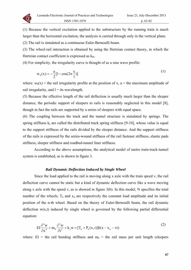
Leonardo Electronic Journal of Practices and Technologies
ISSN 1583-1078
Issue 23 July-December 2013
p 63-82
(1) Because the vertical excitation applied to the substructure by the running train is much
larger than the horizontal excitation the analysis is carried through only in the vertical plane
(2) The rail is simulated as a continuous Euler-Bernoulli beam
(3) The wheel-rail interaction is obtained by using the Hertzian contact theory in which the
Hertzian contact coefficient is expressed as kH
(4) For simplicity the irregularity curve is thought of as a sine wave profile
)]lx2cos(1[
2a)x(w0 πminusminus=
(1)
where w0(x) = the rail irregularity profile at the position of x a = the maximum amplitude of
rail irregularity and l = its wavelength
(5) Because the effective length of the rail deflection is usually much larger than the sleeper
distance the periodic support of sleepers to rails is reasonably neglected in this model [8]
though in fact the rails are supported by a series of sleepers with equal space
(6) The coupling between the track and the tunnel structure is simulated by springs The
spring stiffness ks are called the distributed track spring stiffness [9-10] whose value is equal
to the support stiffness of the rails divided by the sleeper distance And the support stiffness
of the rails is expressed by the series-wound stiffness of the rail fastener stiffness elastic pads
stiffness sleeper stiffness and roadbed-tunnel liner stiffness
According to the above assumptions the analytical model of metro train-track-tunnel
system is established as is shown in figure 3
Rail Dynamic Deflection Induced by Single Wheel
Since the load applied to the rail is moving along x axle with the train speed v the rail
deflection curve cannot be static but a kind of dynamic deflection curve like a wave moving
along x axle with the speed v as is showed in figure 3(b) In this model N specifies the total
number of the wheels Tn and xn are respectively the constant load amplitude and its initial
position of the n-th wheel Based on the theory of Euler-Bernoulli beam the rail dynamic
deflection w(xt) induced by single wheel is governed by the following partial differential
equation
)vtxx()]tx(PT[ wktwm
xwEI nnns2
2
04
4
minusminusδ+=+partpart
+partpart
(2)
where EI = the rail bending stiffness and m0 = the rail mass per unit length (sleepers
67
Analytical Model of Underground Train Induced Vibrations on Nearby Building Structures in Cameroon Assessment and Prediction
Lezin S MINSILI He XIA and Robert M EKO
included) x = the horizontal distance of the constant load Tn = away from coordinate origin
during the process of moving and Pn(xt) = the dynamic contact force between wheel and rail
[11]
a) Geometrical parameters of train and track
(b) Interaction model of metro train-track-tunnel
Figure 3 Analytical model of metro train-track-tunnel system
The initial condition is
0|tw|)tx(w 0t0t =partpart
= == (3)
Also the boundary condition at the infinity is
68
Leonardo Electronic Journal of Practices and Technologies
ISSN 1583-1078
Issue 23 July-December 2013
p 63-82
)3210n(0x
)tx(wlim n
n
x==
partpart
plusmninfinrarr
(4)
Firstly the rail static deflection curve is expressed When the train is static the load
applied to the rail is static constant axle load Tn Correspondingly the rail deformation is
described as a static deflection curve [12-13]
s
0|x|3
nst
kgm|)]x|sin()x[cos(e
EI8Tw +β+βsdottimesβ
= βminus (5)
where the superscript st denotes the static solution and It can be seen from
this equation that the effective length of rail deflection curve is
41s )EI4k(=β
βπ= xst0
Equation (2) shows that the dynamic deflection is induced by two kinds of loads the
moving constant load and the moving dynamic load The solution thus consists of two parts
corresponding to the two loads
For the moving constant load )vtxx(T nn minusminusδ based on Equation (5) the dynamic
deflection curve can be easily expressed as follows
|)]vtxx|sin())vtxx([cos(e]EI8T[)tvtxx(w nn|vtxx|3
nn1n minusminusβη
ηδ
+minusminusβηsdottimesδβ=minusminus minusminusβδminus (6)
where 2min )cv(1minus=δ and 2
min )cv(1+=η with the velocity of
free track waves
4120smin )mEIk4(c =
For the moving dynamic load )vtxx()tx(P nn minusminusδ the Green function of the rail
dynamic deflection induced by unit impulse load is introduced first The dynamic deflection
of the rail under unit impulse load is
)vtxx()tx(Pwkxwm
xwEI nδs2
2
04
4
minusminusδ=+partpart
+partpart
(7)
By using the Laplace transformation Fourier transformation and their corresponding
inverse transformations the final solution of the Green function Equation (7) can be solved
as
ωsdotβminusω
sdotβminusωααπ
= ωinfin+
int de4
)t4sin(m1)tx(G xi
0 44
44
(8)
where mEI=α and 41s )EI4k(=β
69
Analytical Model of Underground Train Induced Vibrations on Nearby Building Structures in Cameroon Assessment and Prediction
Lezin S MINSILI He XIA and Robert M EKO
Based on the generalized Duhamel integral the rail dynamic deflection curve under
the moving dynamic load )vtxx()tx(P nn minusminusδ can be expressed as
ωτsdotβminusω
τminussdotβminusωαtimesτminusminus
απ=
=lowast=minusminus
minusminusωinfin+
int int dde4
)]t(4sin[)vtxx(Pm1
)tx(P)tx(G)tvtxx(w
)vtxx(i
44
44t
0 0 n
n2
n
(9)
Therefore the total dynamic deflection of the rail is the summation of the above two
deflections
)tvtxx(w)tvtxx(w)tvtxx(w n2n1n minusminus+minusminus=minusminus (10)
Since the load applied to rail is moving along x axle with the speed v by introducing
the local coordinate system xloc = x-xn-vt the dynamic deflection of the rail induced by single
wheel can be expressed as
)tx(w)tx(w)tx(w loc2loc1ocl += (11)
where
|)]x|sin()x[cos(e]EI8T[)tx(w locloc|x|3
nloc1loc βη
ηδ
+βηtimestimesδβ= βδminus (12)
ωτsdotβminusω
τminussdotβminusωαtimesτ
απ= ωinfin+
int int dde4
)]t(4sin[)x(Pm1)tx(w locxi
44
44t
0 0 locloc2 (13)
Dynamic Load Applied onto Tunnel
As shown in figure 3(b) the downward force transferred onto the tunnel from each
sleeper equals to the upward spring force bore on this sleeper width expressed as
f(t)=ksΔdw(xloc) herein Δd is the sleeper width and its acting point lies under the sleeper
On the other hand it is not all sleepers but a certain number of sleepers at the range of the
deflection curve effective length that are involved in the distribution of this force endured by
the rail These involved sleepers are called the effective sleepers and if Neff denotes the
number of effective sleepers it can be seen from the model figure that d2xN st0eff asymp
In order to eliminate Δd from the expression of f(t) the rail static deflection equation
(7) is integrated along x in which the influence of m0g is neglected considering that m0g is
much smaller than Tn Due to the non-continuous support of actual sleepers the integral can
be written as the summation of Neff integrals and so there is the expression of
70
Leonardo Electronic Journal of Practices and Technologies
ISSN 1583-1078
Issue 23 July-December 2013
p 63-82
)t(PTdNΔwk nneffstmaxs += The substitution of it into f (t) results in
stmax
loc
eff
nn
w)x(w
N)t(PT)t(f +
= (14)
If gn(xloct) is used to denote the dynamic load at the point of xloc applied onto tunnel
by the n-th wheel the following solution can be obtained by all the above derivations
)xvtxx()idx(w
)x(wN
)t(PT)tx(g nlocstmax
loc
eff
nnlocn minus++δminusδ
+=
(15)
where δ function is introduced to explain that the acting point of this force is below under the
sleeper n = the serial number of the wheel and i = the serial number of the sleeper
corresponding to the force position
The final dynamic force F(xt) applied onto the tunnel by all the N wheels can be
obtained by means of the superposition principle (the original coordinate system is reverted)
)tx(g)vtxxx()idx()tx(F locnn
N
1nloc minusminusminusδminusδ=sum
=
(16)
Substitute Equation (15) into Equation (16) the following expression can be obtained
stmax
nN
1n eff
nn
w)vtxx(w
N)t(PT)idx()tx(F minusminus+
minusδ= sum=
(17)
Discrete Dynamic Model of the System
Ground-born vibrations are the result of the train-track structure exciting the tunnel
and adjacent soil layers and creating waves that propagate to the foundations of nearby
buildings These received vibrations at the foundation propagate throughout other parts of the
building structure [14-19] are showing that the ground-borne vibration due to wheel-tract
trains is function of the geology condition the covering depth the train-track system Since
the response from this vibration input depends on building structural characteristics the
dynamic model is subdivided into different sub-models the train model the track model and
the building model
The train model is composed by a series of wagons each consisting of car body
bogies wheel sets springs and dashpots To simplify to analysis the following hypotheses
71
Analytical Model of Underground Train Induced Vibrations on Nearby Building Structures in Cameroon Assessment and Prediction
Lezin S MINSILI He XIA and Robert M EKO
developed by Xia [20] are made on the vehicle (1) car bodies bogie frame and wheel sets are
rigid without elastic deformation (2) all dampers are viscous (3) lateral movements and
vertical movements of the vehicles are not coupled with each other Thus there are two
degrees of freedom (DOF) (floating and nodding) for each car body and bogie represented by
Zc φc and ZT φT respectively and one DOF for each wheel set (floating Zw) The total DOF
number for a 4-axle train vehicle therefore is ten
The track model consists of rail and rubber pads as seen in figure 4 The assumptions
for the track model are (1) the rail is taken as an endless beam on elastic supports its mass
and stiffness matrix in the dynamic equations while the damping matrix is formed by the
assumption of Rayleigh damping (2) the stiffness and damping of the pads and fasteners are
simplified into a set of compound masses springs and dampers represented by mi ki and ci
respectively (3) The analysis is carried out only in the vertical plane According to these
assumptions there are 2 DOFs (vertical displacement and rotation) for each rail node and one
DOF (vertical movement) for each mass in the elastic support The total number of DOF of
the system therefore is 2N+2n where N is the number of rail nodes and n is the number of
elastic supports sets
Figure 4 Dynamic model of Train-track system
From the assumptions made above the FE dynamic equilibrium equations of the train
and the rail track is assembled into a single relation and the global equilibrium equation of
72
Leonardo Electronic Journal of Practices and Technologies
ISSN 1583-1078
Issue 23 July-December 2013
p 63-82
the train-rail track system is obtained as
)tx(FKZZCZM =++ (18)
Or in matrix form
⎪⎪⎭
⎪⎪⎬
⎫
⎪⎪⎩
⎪⎪⎨
⎧
=
⎪⎪⎭
⎪⎪⎬
⎫
⎪⎪⎩
⎪⎪⎨
⎧
⎥⎥⎥⎥
⎦
⎤
⎢⎢⎢⎢
⎣
⎡
+
⎪⎪⎭
⎪⎪⎬
⎫
⎪⎪⎩
⎪⎪⎨
⎧
⎥⎥⎥⎥
⎦
⎤
⎢⎢⎢⎢
⎣
⎡
+
⎪⎪⎭
⎪⎪⎬
⎫
⎪⎪⎩
⎪⎪⎨
⎧
⎥⎥⎥⎥
⎦
⎤
⎢⎢⎢⎢
⎣
⎡
n
2
1
n
2
1
n
2
1
n
2
1
n
2
1
n
2
1
n
2
1
F
FF
Z
ZZ
K00
0K000K
Z
ZZ
C00
0C000C
Z
ZZ
M00
0M000M
(19)
Where the wheel-rail contact force F(xt) is calculated using the Hertzian contact
theory by using the discrete form of the Train-rail track interaction along the rail axis given
as
[ ]sum δminusminusφ=k
51ijijwijHlijl )x()tx(vZkF (20)
where Zwj(t) = the wheel displacement v(xt) = the rail deflection at the wheel-rail contact
point δ(x) = the wheel or rail profile change kH = the Hertzian contact coefficient n = the
number of vehicles Mi = the mass matrix of the i-th vehicle (being a diagonal matrix we have
Diag Mi=[Mc Jc MT1 MT2 JT2 Mw1 hellip Mw4]) Ki = the vehicle stiffness matrix and Ci =
the damping matrix Zi is the vehicle displacement vector Fi is the force vector of the i-th
vehicle Mn Cn Kn are respectively the mass damping and the stiffness matrices of the track
are respectively the nodal acceleration velocity and displacement vectors as
given in the FE dynamic equation oslashij is the distributive coefficient of the j-th wheel-set to the
i-th rail node
vandvv
Simulation and Analysis of the TSS Interaction
Simulation by the FEM
The FEM is the most widely used numerical method implemented by researchers and
commercial software producers It can be used to solve complex geometries but it requires an
appropriate discrete form of the media being modelled This makes the FEM computationally
unfeasible for very large scale models such as those involving unbounded domains unless
substantial shortcuts are implemented These may entail the use of coarse elements low
frequency simulations or the introduction of boundary artefacts [21] This not being the case
73
Analytical Model of Underground Train Induced Vibrations on Nearby Building Structures in Cameroon Assessment and Prediction
Lezin S MINSILI He XIA and Robert M EKO
of the present work since the soil sub domain and the building sub domain are bounded with
appropriate boundary conditions as seen in the FE element model of the tunnel-soil-building
system shown in figure 5 assuming a 2-D plane strain state The double-track is inside the
single hollow tunnel with a dimension of 10m (height) times12m (width) and with 14m cover
depth The soil is divided into four layers with their parameters shown in Table 1 An 18-
story building is set at 30m from the tunnel centreline which has the pile foundation with
15m length and whose members are all simulated as beam elements
Figure 5 Finite element model of tunnel-soil-building system
Table 1 Parameters of the building and sub soils Materials Elastic modulus
[MPa] Poisson ratio Density
[Nmiddotm-3]Remarks
C30 Concrete 30000 018 2550 Beam (03mtimes06m) Columns (06mtimes06m)
Backfilling soil 29 040 17000 Arenaceous clay 1 127 033 18800 Moderate fine sand 136 037 20200 Arenaceous clay 2 77 028 20000
74
Leonardo Electronic Journal of Practices and Technologies
ISSN 1583-1078
Issue 23 July-December 2013
p 63-82
The vibration evaluation method is settled in accordance with ISO26311-1985 that
adopts the vertical acceleration level in terms of Lz=20log10(aa0) where a is transient
acceleration of the observation points with the unit of ms2 and a0 is the basic acceleration
with the value of 1times10-5ms2 Since the model is asymmetric the whole system must be
analyzed and the FE model should be as large as possible to contain the train length and to
reduce the effect of the wave reflection at the artificial border In this analysis the model
covers a dimension of 650mtimes80m The bottom is assumed to have fixed constraints and the
two sides are spring elements with the stiffness of 500kNm
The damping behaviour of each basic component j of the rail track-ground system was
modelled using the Rayleigh method The damping matrix C can be obtained from the
relation
KMC jjjj βα += (21)
where Mj and Kj are the j-th components of the mass and the stiffness matrices (respectively)
Determination of the parameters αj and βj (as example αj =004 and βj =001) was carried out
using the procedure described by Di Mino [22]
A train composed of 6 cars running on a track of continuous welded rails of 50 kgm is
considered The mass of concrete sleeper is 251 kg and the sleeper space is d=055m The
distributed rail spring stiffness is ks=20246 MNm2 and the wheel-rail contact stiffness
coefficient is kH=1421MNm Implementing the theory and model described above with the
vehicle and track parameters listed in table 2 the dynamic loads applied to the tunnel is
obtained as shown in figure 6
Table 2 Calculation parameters of underground vehicle Vehicle full length L(m) 1952Bogie centrelinesrsquo distance 2s(m) 1266Fixed axle spacing 2d(m) 230 Car body mass Mc(t) 37 Car mass moment of inertia Jc (t-m2) 1700 Bogie mass Mt(t) 360 Bogie mass moment of inertia Jt(t-m2) 962 Bogie spring stiffness Kt (kNm) 2080 Bogie damping coefficient Ct (kNsm) 240 Wheel set mass Mw (t) 170 Wheel spring stiffness (kNm) 2450 Wheel damping coefficient Kw (kNsm) 240
75
Analytical Model of Underground Train Induced Vibrations on Nearby Building Structures in Cameroon Assessment and Prediction
Lezin S MINSILI He XIA and Robert M EKO
a) Dynamic load of train-track system
b) The spectrum of the train-track dynamic load
Figure 6 Characteristics of the dynamic load applied to the tunnel
Analytical Results
The previous figures describe the calculated dynamic load and its frequency spectrum
when the train speed is 50 kmh which clearly show that the force is mainly induced by the
moving axle loads of vehicles and that the load mainly concentrates at the frequency range of
0 to 10Hz This load is adopted as the dynamic load for the next calculation
Figure 7 shows the distribution of ground vibrations at two locations perpendicular to
76
Leonardo Electronic Journal of Practices and Technologies
ISSN 1583-1078
Issue 23 July-December 2013
p 63-82
the tunnel centreline It can be seen that the maximum acceleration within the distance of 30m
(49cms2) is smaller than the maximum level at 0 m (81cms2) The difference between
computed acceleration time histories computed at these locations is due to the vibration
attenuation with distance This attenuation of the peak acceleration from 81 to 49 might be
dependent on the train speed and train loading the geotechnical conditions of the soil and
possibly to the frequency components of the train-track excitation loading that is filtered
throughout soil layers
a) at 0 m from the tunnel centreline
b) at 30 m from the tunnel centreline
Figure 7 Ground acceleration time histories
77
Analytical Model of Underground Train Induced Vibrations on Nearby Building Structures in Cameroon Assessment and Prediction
Lezin S MINSILI He XIA and Robert M EKO
The train still running at the speed of 50kmh the building acceleration time-histories
of the first floor the 8th floor and the top floor are illustrated in figure 8 It can be seen that
the form of acceleration amplitude changes at different floor With the present vibration
amplification of the maximal acceleration response from the first floor to the top floor level it
is obvious that the building structure generates energy with time increment what is easily
noticed at the first floor level in figure 8a
a) at the first floor
b) at the 8-th floor
Figure 8 The acceleration time history at different floor levels
78
Leonardo Electronic Journal of Practices and Technologies
ISSN 1583-1078
Issue 23 July-December 2013
p 63-82
c) at the top level
Figure 8 The acceleration time history at different floor levels
Many investigations support that in a structure under specific modal vibration some of
its parts or elements can be subjected to local resonance and even self-excitation Thus the
observed acceleration amplification from the 3-rd second in figure 8c is related to local
resonance From literature survey [16-17 23-26] it is known that there are no damages on a
building due to train induced ground-borne vibration even if human occupants of the
buildings might be seriously affected But the computed results from the given model shows
that there is the possibility for an underground train passing through an urban area under
specific sub-models described above to excite a particular building or some of its elements
with one of their natural frequencies thus creating the resonance problem Investigations on
this problem are still going on in the Department
Conclusions
The TSS presented in this paper is subdivided into three main sub-models the source
the propagation path and the receiver in order to study and understand the influence of factors
such as dynamic characteristics of the train the railway structure soil and building
characteristics on ground-born vibrations and their effects on nearby building structures
By dividing the TSS model into sub-models it is possible to replace some parts of the
model with data from a particular site if available Thus if a new railway is being designed
79
Analytical Model of Underground Train Induced Vibrations on Nearby Building Structures in Cameroon Assessment and Prediction
Lezin S MINSILI He XIA and Robert M EKO
close to a building a prediction with good accuracy can be made on the effects of the
anticipated railway on the building
With the limitations of available data on TSS interaction in Cameroon experiments
and measurements are still to be done at sites with different geotechnical conditions different
train-track models and different building types to validate obtained results and thus elucidate
these important facts
Acknowledgements
This paper is a continuation of the study presented at the ldquo3rd International Symposium
on Environmental Vibrations Prediction Monitoring Mitigation and Evaluationrdquo 2007
References
1 The World Bank Cameroon Upgrading Low Income Urban Settlements - Country
Assessment Report 2002 AFTU 1 amp 2 Available at
httpwebmiteduurbanupgradingupgradingcase-examplesoverview-africacountry-
assessmentsdownloadCAMEROONpdf (accessed 08062013)
2 NRMP The National Railway Network Master Plan in Cameroon Final report of the
prefeasibility study conducted by KORPEC (KORea Port Engineering Corporation) and
Validated by the Government of Cameroon 2012 p 390-402
3 Du XT Xu Y L Xia H Dynamic interaction of bridgendashtrain system under non-
uniform seismic ground motion Earthquake Engineering Structural Dynamics 2012
41 p 139-157 DOI 101002eqe1122
4 Rodriacuteguez-Tembleque L Abascal R A 3D FEMndashBEM Rolling Contact Formulation
for Unstructured Meshes International Journal of Solids and Structures 2010 47 p
330-353 Available at
httpwwwsciencedirectcomsciencearticlepiiS0020768309003953 (accessed
08062013)
5 Zolghadr Jahromi H Izzuddin BA Zdravkovic L Partitioned analysis of nonlinear
80
Leonardo Electronic Journal of Practices and Technologies
ISSN 1583-1078
Issue 23 July-December 2013
p 63-82
soil-structure interaction using iterative coupling Interaction and Multiscale
Mechanics 2007 1(1) p 33-51
6 Xia H Dynamic Interaction of Vehicles and Structures Science Press Beijing China
2002
7 Chore HS Ingle RK Sawant VA Building frame - pile foundation - soil interaction
analysis a parametric study Interaction and Multiscale Mechanics 2010 3(1) p 55-
79
8 Krylov VV Effects of track properties on ground vibrations generated by high-speed
trains ACUSTICA-Acta Acustica 1998 84(1) p 78-90
9 Daumueller AN Jauregui DV Strain-Based Evaluation of a Steel Through-Girder
Railroad Bridge Hindawi Publishing Corporation Advances in Civil Engineering
2012 Available at httpwwwhindawicomjournalsamseai(accessed 17062013)
10 Xiaoyan L Numerical Analysis of Track Structures in Railway Beijing China Railway
Press 1998
11 Grassie SL Gregory RW Dynamic response of railway track to high frequency
vertical excitation Journal of Mechanical Engineering Science 1982 24(2) p 77-90
12 Flyacuteba L Vibration of Solids and Structures Under Moving Loads London Thomas
Telford 1999
13 Weitsman Y On foundations that react in compression only Journal of Applied
Mechanics 1970 12 p 1019-1030
14 Wang K Liu P Lateral Stability Analysis of Heavy-Haul Vehicle on Curved Track
Based on WheelRail Coupled Dynamics Journal of Transportation Technologies 2012
2(2) p 150-157 Available at httpwwwSciRPorgjournaljtts (accessed 08062013)
15 Woods RD Screening of Surface Waves in Soils Journal of Soil Mechanics and
Foundation Division Proceedings of the ASCE 1968
16 Woods RD Larry PJ Energy-Attenuation Relationships from Construction
Vibrations Vibration Problems in Geotechnical Engineering ASCE Proceedings
Detroit Michigan 1985
17 Eisenman J Deischl F Structure-Borne Sound from Underground Railway Systems
81
Analytical Model of Underground Train Induced Vibrations on Nearby Building Structures in Cameroon Assessment and Prediction
Lezin S MINSILI He XIA and Robert M EKO
82
Der Eisenbahningenieur 1986 3 p 101-110
18 Alshawi M Underwood J Improving the constructability of design solutions through
an integrated system Journal of Engineering Construction and Architectural
Management 1993 3(1amp2) p 47ndash67 doi101108eb021022
19 Patrick C Low Vibration and Noise Track Systems with Tunable Properties for Modern
LRTStreetcar Track on Surface in Urban Areas TIVCrsquo2001 International Symposium
on Traffic Induced Vibrations amp Controls Beijing China 2001 p 161-176
20 Xia H Cao YM Zhang N Numerical Analysis of Vibration Effects of Metro Trains
on Surrounding Environment Int J of Structural Stability and Dynamics 2007 7 p
45-56
21 Le Kouby A Bourgeois E Rocher-Lacoste F Subgrade Improvement Method for
Existing Railway Lines ndash an Experimental and Numerical Study Electronic Journal of
Geotechnical Engineering 2010 15 p461-494
22 Di Mino G Di Liberto CM Nigrelli J A FEM model of rail track-ground system to
calculate the ground borne vibrations a case of rail track with wooden sleepers and k-
fastenings at Castelvetrano Advanced Characterisation of Pavement and Soil
Engineering Materials Athens Greece 2007 p 1737-1752
23 Chauhan HM Pomal MM Bhuta GN A Comparative Study Of Wind Forces On
High-Rise Buildings as Per Is 875-Iii (1987) and Proposed Draft Code (2011) GRA -
Global Research Analysis 2013 2(5) p 59-60
24 Lei X Zhang B Influence of track stiffness distribution on vehicle and track
interactions in track transition Proceedings of the Institution of Mechanical Engineers
Part F Journal of Rail and Rapid Transit 2010 224592 p 592-604 Available at
httppifsagepubcomcontent2246592 (accessed 28082012)
25 Thorat YV Kadam SS Design and Development of Test Setup for VibrationAnalysis
with Soft Foot Indian Journal of Applied Research 2012 2(3) p 59-62
26 Xiaojing Sun Weining Liu Dawen Xie Yingxuan Jia Vibration impacts on adjacent
sensitive buildings induced by metro trains World Tunnel Congress 2008 -
Underground Facilities for Better Environment and Safety ndash India Agra 2008 p 1382-
1389
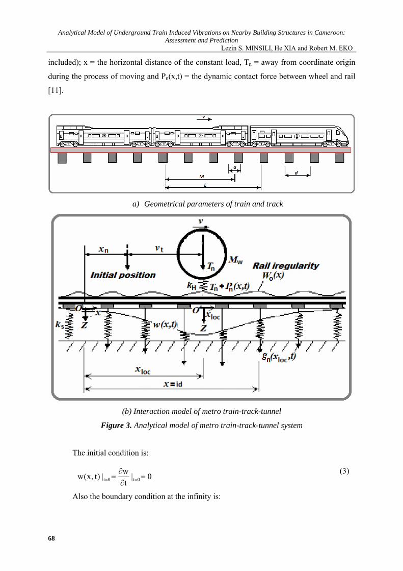
Analytical Model of Underground Train Induced Vibrations on Nearby Building Structures in Cameroon Assessment and Prediction
Lezin S MINSILI He XIA and Robert M EKO
included) x = the horizontal distance of the constant load Tn = away from coordinate origin
during the process of moving and Pn(xt) = the dynamic contact force between wheel and rail
[11]
a) Geometrical parameters of train and track
(b) Interaction model of metro train-track-tunnel
Figure 3 Analytical model of metro train-track-tunnel system
The initial condition is
0|tw|)tx(w 0t0t =partpart
= == (3)
Also the boundary condition at the infinity is
68
Leonardo Electronic Journal of Practices and Technologies
ISSN 1583-1078
Issue 23 July-December 2013
p 63-82
)3210n(0x
)tx(wlim n
n
x==
partpart
plusmninfinrarr
(4)
Firstly the rail static deflection curve is expressed When the train is static the load
applied to the rail is static constant axle load Tn Correspondingly the rail deformation is
described as a static deflection curve [12-13]
s
0|x|3
nst
kgm|)]x|sin()x[cos(e
EI8Tw +β+βsdottimesβ
= βminus (5)
where the superscript st denotes the static solution and It can be seen from
this equation that the effective length of rail deflection curve is
41s )EI4k(=β
βπ= xst0
Equation (2) shows that the dynamic deflection is induced by two kinds of loads the
moving constant load and the moving dynamic load The solution thus consists of two parts
corresponding to the two loads
For the moving constant load )vtxx(T nn minusminusδ based on Equation (5) the dynamic
deflection curve can be easily expressed as follows
|)]vtxx|sin())vtxx([cos(e]EI8T[)tvtxx(w nn|vtxx|3
nn1n minusminusβη
ηδ
+minusminusβηsdottimesδβ=minusminus minusminusβδminus (6)
where 2min )cv(1minus=δ and 2
min )cv(1+=η with the velocity of
free track waves
4120smin )mEIk4(c =
For the moving dynamic load )vtxx()tx(P nn minusminusδ the Green function of the rail
dynamic deflection induced by unit impulse load is introduced first The dynamic deflection
of the rail under unit impulse load is
)vtxx()tx(Pwkxwm
xwEI nδs2
2
04
4
minusminusδ=+partpart
+partpart
(7)
By using the Laplace transformation Fourier transformation and their corresponding
inverse transformations the final solution of the Green function Equation (7) can be solved
as
ωsdotβminusω
sdotβminusωααπ
= ωinfin+
int de4
)t4sin(m1)tx(G xi
0 44
44
(8)
where mEI=α and 41s )EI4k(=β
69
Analytical Model of Underground Train Induced Vibrations on Nearby Building Structures in Cameroon Assessment and Prediction
Lezin S MINSILI He XIA and Robert M EKO
Based on the generalized Duhamel integral the rail dynamic deflection curve under
the moving dynamic load )vtxx()tx(P nn minusminusδ can be expressed as
ωτsdotβminusω
τminussdotβminusωαtimesτminusminus
απ=
=lowast=minusminus
minusminusωinfin+
int int dde4
)]t(4sin[)vtxx(Pm1
)tx(P)tx(G)tvtxx(w
)vtxx(i
44
44t
0 0 n
n2
n
(9)
Therefore the total dynamic deflection of the rail is the summation of the above two
deflections
)tvtxx(w)tvtxx(w)tvtxx(w n2n1n minusminus+minusminus=minusminus (10)
Since the load applied to rail is moving along x axle with the speed v by introducing
the local coordinate system xloc = x-xn-vt the dynamic deflection of the rail induced by single
wheel can be expressed as
)tx(w)tx(w)tx(w loc2loc1ocl += (11)
where
|)]x|sin()x[cos(e]EI8T[)tx(w locloc|x|3
nloc1loc βη
ηδ
+βηtimestimesδβ= βδminus (12)
ωτsdotβminusω
τminussdotβminusωαtimesτ
απ= ωinfin+
int int dde4
)]t(4sin[)x(Pm1)tx(w locxi
44
44t
0 0 locloc2 (13)
Dynamic Load Applied onto Tunnel
As shown in figure 3(b) the downward force transferred onto the tunnel from each
sleeper equals to the upward spring force bore on this sleeper width expressed as
f(t)=ksΔdw(xloc) herein Δd is the sleeper width and its acting point lies under the sleeper
On the other hand it is not all sleepers but a certain number of sleepers at the range of the
deflection curve effective length that are involved in the distribution of this force endured by
the rail These involved sleepers are called the effective sleepers and if Neff denotes the
number of effective sleepers it can be seen from the model figure that d2xN st0eff asymp
In order to eliminate Δd from the expression of f(t) the rail static deflection equation
(7) is integrated along x in which the influence of m0g is neglected considering that m0g is
much smaller than Tn Due to the non-continuous support of actual sleepers the integral can
be written as the summation of Neff integrals and so there is the expression of
70
Leonardo Electronic Journal of Practices and Technologies
ISSN 1583-1078
Issue 23 July-December 2013
p 63-82
)t(PTdNΔwk nneffstmaxs += The substitution of it into f (t) results in
stmax
loc
eff
nn
w)x(w
N)t(PT)t(f +
= (14)
If gn(xloct) is used to denote the dynamic load at the point of xloc applied onto tunnel
by the n-th wheel the following solution can be obtained by all the above derivations
)xvtxx()idx(w
)x(wN
)t(PT)tx(g nlocstmax
loc
eff
nnlocn minus++δminusδ
+=
(15)
where δ function is introduced to explain that the acting point of this force is below under the
sleeper n = the serial number of the wheel and i = the serial number of the sleeper
corresponding to the force position
The final dynamic force F(xt) applied onto the tunnel by all the N wheels can be
obtained by means of the superposition principle (the original coordinate system is reverted)
)tx(g)vtxxx()idx()tx(F locnn
N
1nloc minusminusminusδminusδ=sum
=
(16)
Substitute Equation (15) into Equation (16) the following expression can be obtained
stmax
nN
1n eff
nn
w)vtxx(w
N)t(PT)idx()tx(F minusminus+
minusδ= sum=
(17)
Discrete Dynamic Model of the System
Ground-born vibrations are the result of the train-track structure exciting the tunnel
and adjacent soil layers and creating waves that propagate to the foundations of nearby
buildings These received vibrations at the foundation propagate throughout other parts of the
building structure [14-19] are showing that the ground-borne vibration due to wheel-tract
trains is function of the geology condition the covering depth the train-track system Since
the response from this vibration input depends on building structural characteristics the
dynamic model is subdivided into different sub-models the train model the track model and
the building model
The train model is composed by a series of wagons each consisting of car body
bogies wheel sets springs and dashpots To simplify to analysis the following hypotheses
71
Analytical Model of Underground Train Induced Vibrations on Nearby Building Structures in Cameroon Assessment and Prediction
Lezin S MINSILI He XIA and Robert M EKO
developed by Xia [20] are made on the vehicle (1) car bodies bogie frame and wheel sets are
rigid without elastic deformation (2) all dampers are viscous (3) lateral movements and
vertical movements of the vehicles are not coupled with each other Thus there are two
degrees of freedom (DOF) (floating and nodding) for each car body and bogie represented by
Zc φc and ZT φT respectively and one DOF for each wheel set (floating Zw) The total DOF
number for a 4-axle train vehicle therefore is ten
The track model consists of rail and rubber pads as seen in figure 4 The assumptions
for the track model are (1) the rail is taken as an endless beam on elastic supports its mass
and stiffness matrix in the dynamic equations while the damping matrix is formed by the
assumption of Rayleigh damping (2) the stiffness and damping of the pads and fasteners are
simplified into a set of compound masses springs and dampers represented by mi ki and ci
respectively (3) The analysis is carried out only in the vertical plane According to these
assumptions there are 2 DOFs (vertical displacement and rotation) for each rail node and one
DOF (vertical movement) for each mass in the elastic support The total number of DOF of
the system therefore is 2N+2n where N is the number of rail nodes and n is the number of
elastic supports sets
Figure 4 Dynamic model of Train-track system
From the assumptions made above the FE dynamic equilibrium equations of the train
and the rail track is assembled into a single relation and the global equilibrium equation of
72
Leonardo Electronic Journal of Practices and Technologies
ISSN 1583-1078
Issue 23 July-December 2013
p 63-82
the train-rail track system is obtained as
)tx(FKZZCZM =++ (18)
Or in matrix form
⎪⎪⎭
⎪⎪⎬
⎫
⎪⎪⎩
⎪⎪⎨
⎧
=
⎪⎪⎭
⎪⎪⎬
⎫
⎪⎪⎩
⎪⎪⎨
⎧
⎥⎥⎥⎥
⎦
⎤
⎢⎢⎢⎢
⎣
⎡
+
⎪⎪⎭
⎪⎪⎬
⎫
⎪⎪⎩
⎪⎪⎨
⎧
⎥⎥⎥⎥
⎦
⎤
⎢⎢⎢⎢
⎣
⎡
+
⎪⎪⎭
⎪⎪⎬
⎫
⎪⎪⎩
⎪⎪⎨
⎧
⎥⎥⎥⎥
⎦
⎤
⎢⎢⎢⎢
⎣
⎡
n
2
1
n
2
1
n
2
1
n
2
1
n
2
1
n
2
1
n
2
1
F
FF
Z
ZZ
K00
0K000K
Z
ZZ
C00
0C000C
Z
ZZ
M00
0M000M
(19)
Where the wheel-rail contact force F(xt) is calculated using the Hertzian contact
theory by using the discrete form of the Train-rail track interaction along the rail axis given
as
[ ]sum δminusminusφ=k
51ijijwijHlijl )x()tx(vZkF (20)
where Zwj(t) = the wheel displacement v(xt) = the rail deflection at the wheel-rail contact
point δ(x) = the wheel or rail profile change kH = the Hertzian contact coefficient n = the
number of vehicles Mi = the mass matrix of the i-th vehicle (being a diagonal matrix we have
Diag Mi=[Mc Jc MT1 MT2 JT2 Mw1 hellip Mw4]) Ki = the vehicle stiffness matrix and Ci =
the damping matrix Zi is the vehicle displacement vector Fi is the force vector of the i-th
vehicle Mn Cn Kn are respectively the mass damping and the stiffness matrices of the track
are respectively the nodal acceleration velocity and displacement vectors as
given in the FE dynamic equation oslashij is the distributive coefficient of the j-th wheel-set to the
i-th rail node
vandvv
Simulation and Analysis of the TSS Interaction
Simulation by the FEM
The FEM is the most widely used numerical method implemented by researchers and
commercial software producers It can be used to solve complex geometries but it requires an
appropriate discrete form of the media being modelled This makes the FEM computationally
unfeasible for very large scale models such as those involving unbounded domains unless
substantial shortcuts are implemented These may entail the use of coarse elements low
frequency simulations or the introduction of boundary artefacts [21] This not being the case
73
Analytical Model of Underground Train Induced Vibrations on Nearby Building Structures in Cameroon Assessment and Prediction
Lezin S MINSILI He XIA and Robert M EKO
of the present work since the soil sub domain and the building sub domain are bounded with
appropriate boundary conditions as seen in the FE element model of the tunnel-soil-building
system shown in figure 5 assuming a 2-D plane strain state The double-track is inside the
single hollow tunnel with a dimension of 10m (height) times12m (width) and with 14m cover
depth The soil is divided into four layers with their parameters shown in Table 1 An 18-
story building is set at 30m from the tunnel centreline which has the pile foundation with
15m length and whose members are all simulated as beam elements
Figure 5 Finite element model of tunnel-soil-building system
Table 1 Parameters of the building and sub soils Materials Elastic modulus
[MPa] Poisson ratio Density
[Nmiddotm-3]Remarks
C30 Concrete 30000 018 2550 Beam (03mtimes06m) Columns (06mtimes06m)
Backfilling soil 29 040 17000 Arenaceous clay 1 127 033 18800 Moderate fine sand 136 037 20200 Arenaceous clay 2 77 028 20000
74
Leonardo Electronic Journal of Practices and Technologies
ISSN 1583-1078
Issue 23 July-December 2013
p 63-82
The vibration evaluation method is settled in accordance with ISO26311-1985 that
adopts the vertical acceleration level in terms of Lz=20log10(aa0) where a is transient
acceleration of the observation points with the unit of ms2 and a0 is the basic acceleration
with the value of 1times10-5ms2 Since the model is asymmetric the whole system must be
analyzed and the FE model should be as large as possible to contain the train length and to
reduce the effect of the wave reflection at the artificial border In this analysis the model
covers a dimension of 650mtimes80m The bottom is assumed to have fixed constraints and the
two sides are spring elements with the stiffness of 500kNm
The damping behaviour of each basic component j of the rail track-ground system was
modelled using the Rayleigh method The damping matrix C can be obtained from the
relation
KMC jjjj βα += (21)
where Mj and Kj are the j-th components of the mass and the stiffness matrices (respectively)
Determination of the parameters αj and βj (as example αj =004 and βj =001) was carried out
using the procedure described by Di Mino [22]
A train composed of 6 cars running on a track of continuous welded rails of 50 kgm is
considered The mass of concrete sleeper is 251 kg and the sleeper space is d=055m The
distributed rail spring stiffness is ks=20246 MNm2 and the wheel-rail contact stiffness
coefficient is kH=1421MNm Implementing the theory and model described above with the
vehicle and track parameters listed in table 2 the dynamic loads applied to the tunnel is
obtained as shown in figure 6
Table 2 Calculation parameters of underground vehicle Vehicle full length L(m) 1952Bogie centrelinesrsquo distance 2s(m) 1266Fixed axle spacing 2d(m) 230 Car body mass Mc(t) 37 Car mass moment of inertia Jc (t-m2) 1700 Bogie mass Mt(t) 360 Bogie mass moment of inertia Jt(t-m2) 962 Bogie spring stiffness Kt (kNm) 2080 Bogie damping coefficient Ct (kNsm) 240 Wheel set mass Mw (t) 170 Wheel spring stiffness (kNm) 2450 Wheel damping coefficient Kw (kNsm) 240
75
Analytical Model of Underground Train Induced Vibrations on Nearby Building Structures in Cameroon Assessment and Prediction
Lezin S MINSILI He XIA and Robert M EKO
a) Dynamic load of train-track system
b) The spectrum of the train-track dynamic load
Figure 6 Characteristics of the dynamic load applied to the tunnel
Analytical Results
The previous figures describe the calculated dynamic load and its frequency spectrum
when the train speed is 50 kmh which clearly show that the force is mainly induced by the
moving axle loads of vehicles and that the load mainly concentrates at the frequency range of
0 to 10Hz This load is adopted as the dynamic load for the next calculation
Figure 7 shows the distribution of ground vibrations at two locations perpendicular to
76
Leonardo Electronic Journal of Practices and Technologies
ISSN 1583-1078
Issue 23 July-December 2013
p 63-82
the tunnel centreline It can be seen that the maximum acceleration within the distance of 30m
(49cms2) is smaller than the maximum level at 0 m (81cms2) The difference between
computed acceleration time histories computed at these locations is due to the vibration
attenuation with distance This attenuation of the peak acceleration from 81 to 49 might be
dependent on the train speed and train loading the geotechnical conditions of the soil and
possibly to the frequency components of the train-track excitation loading that is filtered
throughout soil layers
a) at 0 m from the tunnel centreline
b) at 30 m from the tunnel centreline
Figure 7 Ground acceleration time histories
77
Analytical Model of Underground Train Induced Vibrations on Nearby Building Structures in Cameroon Assessment and Prediction
Lezin S MINSILI He XIA and Robert M EKO
The train still running at the speed of 50kmh the building acceleration time-histories
of the first floor the 8th floor and the top floor are illustrated in figure 8 It can be seen that
the form of acceleration amplitude changes at different floor With the present vibration
amplification of the maximal acceleration response from the first floor to the top floor level it
is obvious that the building structure generates energy with time increment what is easily
noticed at the first floor level in figure 8a
a) at the first floor
b) at the 8-th floor
Figure 8 The acceleration time history at different floor levels
78
Leonardo Electronic Journal of Practices and Technologies
ISSN 1583-1078
Issue 23 July-December 2013
p 63-82
c) at the top level
Figure 8 The acceleration time history at different floor levels
Many investigations support that in a structure under specific modal vibration some of
its parts or elements can be subjected to local resonance and even self-excitation Thus the
observed acceleration amplification from the 3-rd second in figure 8c is related to local
resonance From literature survey [16-17 23-26] it is known that there are no damages on a
building due to train induced ground-borne vibration even if human occupants of the
buildings might be seriously affected But the computed results from the given model shows
that there is the possibility for an underground train passing through an urban area under
specific sub-models described above to excite a particular building or some of its elements
with one of their natural frequencies thus creating the resonance problem Investigations on
this problem are still going on in the Department
Conclusions
The TSS presented in this paper is subdivided into three main sub-models the source
the propagation path and the receiver in order to study and understand the influence of factors
such as dynamic characteristics of the train the railway structure soil and building
characteristics on ground-born vibrations and their effects on nearby building structures
By dividing the TSS model into sub-models it is possible to replace some parts of the
model with data from a particular site if available Thus if a new railway is being designed
79
Analytical Model of Underground Train Induced Vibrations on Nearby Building Structures in Cameroon Assessment and Prediction
Lezin S MINSILI He XIA and Robert M EKO
close to a building a prediction with good accuracy can be made on the effects of the
anticipated railway on the building
With the limitations of available data on TSS interaction in Cameroon experiments
and measurements are still to be done at sites with different geotechnical conditions different
train-track models and different building types to validate obtained results and thus elucidate
these important facts
Acknowledgements
This paper is a continuation of the study presented at the ldquo3rd International Symposium
on Environmental Vibrations Prediction Monitoring Mitigation and Evaluationrdquo 2007
References
1 The World Bank Cameroon Upgrading Low Income Urban Settlements - Country
Assessment Report 2002 AFTU 1 amp 2 Available at
httpwebmiteduurbanupgradingupgradingcase-examplesoverview-africacountry-
assessmentsdownloadCAMEROONpdf (accessed 08062013)
2 NRMP The National Railway Network Master Plan in Cameroon Final report of the
prefeasibility study conducted by KORPEC (KORea Port Engineering Corporation) and
Validated by the Government of Cameroon 2012 p 390-402
3 Du XT Xu Y L Xia H Dynamic interaction of bridgendashtrain system under non-
uniform seismic ground motion Earthquake Engineering Structural Dynamics 2012
41 p 139-157 DOI 101002eqe1122
4 Rodriacuteguez-Tembleque L Abascal R A 3D FEMndashBEM Rolling Contact Formulation
for Unstructured Meshes International Journal of Solids and Structures 2010 47 p
330-353 Available at
httpwwwsciencedirectcomsciencearticlepiiS0020768309003953 (accessed
08062013)
5 Zolghadr Jahromi H Izzuddin BA Zdravkovic L Partitioned analysis of nonlinear
80
Leonardo Electronic Journal of Practices and Technologies
ISSN 1583-1078
Issue 23 July-December 2013
p 63-82
soil-structure interaction using iterative coupling Interaction and Multiscale
Mechanics 2007 1(1) p 33-51
6 Xia H Dynamic Interaction of Vehicles and Structures Science Press Beijing China
2002
7 Chore HS Ingle RK Sawant VA Building frame - pile foundation - soil interaction
analysis a parametric study Interaction and Multiscale Mechanics 2010 3(1) p 55-
79
8 Krylov VV Effects of track properties on ground vibrations generated by high-speed
trains ACUSTICA-Acta Acustica 1998 84(1) p 78-90
9 Daumueller AN Jauregui DV Strain-Based Evaluation of a Steel Through-Girder
Railroad Bridge Hindawi Publishing Corporation Advances in Civil Engineering
2012 Available at httpwwwhindawicomjournalsamseai(accessed 17062013)
10 Xiaoyan L Numerical Analysis of Track Structures in Railway Beijing China Railway
Press 1998
11 Grassie SL Gregory RW Dynamic response of railway track to high frequency
vertical excitation Journal of Mechanical Engineering Science 1982 24(2) p 77-90
12 Flyacuteba L Vibration of Solids and Structures Under Moving Loads London Thomas
Telford 1999
13 Weitsman Y On foundations that react in compression only Journal of Applied
Mechanics 1970 12 p 1019-1030
14 Wang K Liu P Lateral Stability Analysis of Heavy-Haul Vehicle on Curved Track
Based on WheelRail Coupled Dynamics Journal of Transportation Technologies 2012
2(2) p 150-157 Available at httpwwwSciRPorgjournaljtts (accessed 08062013)
15 Woods RD Screening of Surface Waves in Soils Journal of Soil Mechanics and
Foundation Division Proceedings of the ASCE 1968
16 Woods RD Larry PJ Energy-Attenuation Relationships from Construction
Vibrations Vibration Problems in Geotechnical Engineering ASCE Proceedings
Detroit Michigan 1985
17 Eisenman J Deischl F Structure-Borne Sound from Underground Railway Systems
81
Analytical Model of Underground Train Induced Vibrations on Nearby Building Structures in Cameroon Assessment and Prediction
Lezin S MINSILI He XIA and Robert M EKO
82
Der Eisenbahningenieur 1986 3 p 101-110
18 Alshawi M Underwood J Improving the constructability of design solutions through
an integrated system Journal of Engineering Construction and Architectural
Management 1993 3(1amp2) p 47ndash67 doi101108eb021022
19 Patrick C Low Vibration and Noise Track Systems with Tunable Properties for Modern
LRTStreetcar Track on Surface in Urban Areas TIVCrsquo2001 International Symposium
on Traffic Induced Vibrations amp Controls Beijing China 2001 p 161-176
20 Xia H Cao YM Zhang N Numerical Analysis of Vibration Effects of Metro Trains
on Surrounding Environment Int J of Structural Stability and Dynamics 2007 7 p
45-56
21 Le Kouby A Bourgeois E Rocher-Lacoste F Subgrade Improvement Method for
Existing Railway Lines ndash an Experimental and Numerical Study Electronic Journal of
Geotechnical Engineering 2010 15 p461-494
22 Di Mino G Di Liberto CM Nigrelli J A FEM model of rail track-ground system to
calculate the ground borne vibrations a case of rail track with wooden sleepers and k-
fastenings at Castelvetrano Advanced Characterisation of Pavement and Soil
Engineering Materials Athens Greece 2007 p 1737-1752
23 Chauhan HM Pomal MM Bhuta GN A Comparative Study Of Wind Forces On
High-Rise Buildings as Per Is 875-Iii (1987) and Proposed Draft Code (2011) GRA -
Global Research Analysis 2013 2(5) p 59-60
24 Lei X Zhang B Influence of track stiffness distribution on vehicle and track
interactions in track transition Proceedings of the Institution of Mechanical Engineers
Part F Journal of Rail and Rapid Transit 2010 224592 p 592-604 Available at
httppifsagepubcomcontent2246592 (accessed 28082012)
25 Thorat YV Kadam SS Design and Development of Test Setup for VibrationAnalysis
with Soft Foot Indian Journal of Applied Research 2012 2(3) p 59-62
26 Xiaojing Sun Weining Liu Dawen Xie Yingxuan Jia Vibration impacts on adjacent
sensitive buildings induced by metro trains World Tunnel Congress 2008 -
Underground Facilities for Better Environment and Safety ndash India Agra 2008 p 1382-
1389
Leonardo Electronic Journal of Practices and Technologies
ISSN 1583-1078
Issue 23 July-December 2013
p 63-82
)3210n(0x
)tx(wlim n
n
x==
partpart
plusmninfinrarr
(4)
Firstly the rail static deflection curve is expressed When the train is static the load
applied to the rail is static constant axle load Tn Correspondingly the rail deformation is
described as a static deflection curve [12-13]
s
0|x|3
nst
kgm|)]x|sin()x[cos(e
EI8Tw +β+βsdottimesβ
= βminus (5)
where the superscript st denotes the static solution and It can be seen from
this equation that the effective length of rail deflection curve is
41s )EI4k(=β
βπ= xst0
Equation (2) shows that the dynamic deflection is induced by two kinds of loads the
moving constant load and the moving dynamic load The solution thus consists of two parts
corresponding to the two loads
For the moving constant load )vtxx(T nn minusminusδ based on Equation (5) the dynamic
deflection curve can be easily expressed as follows
|)]vtxx|sin())vtxx([cos(e]EI8T[)tvtxx(w nn|vtxx|3
nn1n minusminusβη
ηδ
+minusminusβηsdottimesδβ=minusminus minusminusβδminus (6)
where 2min )cv(1minus=δ and 2
min )cv(1+=η with the velocity of
free track waves
4120smin )mEIk4(c =
For the moving dynamic load )vtxx()tx(P nn minusminusδ the Green function of the rail
dynamic deflection induced by unit impulse load is introduced first The dynamic deflection
of the rail under unit impulse load is
)vtxx()tx(Pwkxwm
xwEI nδs2
2
04
4
minusminusδ=+partpart
+partpart
(7)
By using the Laplace transformation Fourier transformation and their corresponding
inverse transformations the final solution of the Green function Equation (7) can be solved
as
ωsdotβminusω
sdotβminusωααπ
= ωinfin+
int de4
)t4sin(m1)tx(G xi
0 44
44
(8)
where mEI=α and 41s )EI4k(=β
69
Analytical Model of Underground Train Induced Vibrations on Nearby Building Structures in Cameroon Assessment and Prediction
Lezin S MINSILI He XIA and Robert M EKO
Based on the generalized Duhamel integral the rail dynamic deflection curve under
the moving dynamic load )vtxx()tx(P nn minusminusδ can be expressed as
ωτsdotβminusω
τminussdotβminusωαtimesτminusminus
απ=
=lowast=minusminus
minusminusωinfin+
int int dde4
)]t(4sin[)vtxx(Pm1
)tx(P)tx(G)tvtxx(w
)vtxx(i
44
44t
0 0 n
n2
n
(9)
Therefore the total dynamic deflection of the rail is the summation of the above two
deflections
)tvtxx(w)tvtxx(w)tvtxx(w n2n1n minusminus+minusminus=minusminus (10)
Since the load applied to rail is moving along x axle with the speed v by introducing
the local coordinate system xloc = x-xn-vt the dynamic deflection of the rail induced by single
wheel can be expressed as
)tx(w)tx(w)tx(w loc2loc1ocl += (11)
where
|)]x|sin()x[cos(e]EI8T[)tx(w locloc|x|3
nloc1loc βη
ηδ
+βηtimestimesδβ= βδminus (12)
ωτsdotβminusω
τminussdotβminusωαtimesτ
απ= ωinfin+
int int dde4
)]t(4sin[)x(Pm1)tx(w locxi
44
44t
0 0 locloc2 (13)
Dynamic Load Applied onto Tunnel
As shown in figure 3(b) the downward force transferred onto the tunnel from each
sleeper equals to the upward spring force bore on this sleeper width expressed as
f(t)=ksΔdw(xloc) herein Δd is the sleeper width and its acting point lies under the sleeper
On the other hand it is not all sleepers but a certain number of sleepers at the range of the
deflection curve effective length that are involved in the distribution of this force endured by
the rail These involved sleepers are called the effective sleepers and if Neff denotes the
number of effective sleepers it can be seen from the model figure that d2xN st0eff asymp
In order to eliminate Δd from the expression of f(t) the rail static deflection equation
(7) is integrated along x in which the influence of m0g is neglected considering that m0g is
much smaller than Tn Due to the non-continuous support of actual sleepers the integral can
be written as the summation of Neff integrals and so there is the expression of
70
Leonardo Electronic Journal of Practices and Technologies
ISSN 1583-1078
Issue 23 July-December 2013
p 63-82
)t(PTdNΔwk nneffstmaxs += The substitution of it into f (t) results in
stmax
loc
eff
nn
w)x(w
N)t(PT)t(f +
= (14)
If gn(xloct) is used to denote the dynamic load at the point of xloc applied onto tunnel
by the n-th wheel the following solution can be obtained by all the above derivations
)xvtxx()idx(w
)x(wN
)t(PT)tx(g nlocstmax
loc
eff
nnlocn minus++δminusδ
+=
(15)
where δ function is introduced to explain that the acting point of this force is below under the
sleeper n = the serial number of the wheel and i = the serial number of the sleeper
corresponding to the force position
The final dynamic force F(xt) applied onto the tunnel by all the N wheels can be
obtained by means of the superposition principle (the original coordinate system is reverted)
)tx(g)vtxxx()idx()tx(F locnn
N
1nloc minusminusminusδminusδ=sum
=
(16)
Substitute Equation (15) into Equation (16) the following expression can be obtained
stmax
nN
1n eff
nn
w)vtxx(w
N)t(PT)idx()tx(F minusminus+
minusδ= sum=
(17)
Discrete Dynamic Model of the System
Ground-born vibrations are the result of the train-track structure exciting the tunnel
and adjacent soil layers and creating waves that propagate to the foundations of nearby
buildings These received vibrations at the foundation propagate throughout other parts of the
building structure [14-19] are showing that the ground-borne vibration due to wheel-tract
trains is function of the geology condition the covering depth the train-track system Since
the response from this vibration input depends on building structural characteristics the
dynamic model is subdivided into different sub-models the train model the track model and
the building model
The train model is composed by a series of wagons each consisting of car body
bogies wheel sets springs and dashpots To simplify to analysis the following hypotheses
71
Analytical Model of Underground Train Induced Vibrations on Nearby Building Structures in Cameroon Assessment and Prediction
Lezin S MINSILI He XIA and Robert M EKO
developed by Xia [20] are made on the vehicle (1) car bodies bogie frame and wheel sets are
rigid without elastic deformation (2) all dampers are viscous (3) lateral movements and
vertical movements of the vehicles are not coupled with each other Thus there are two
degrees of freedom (DOF) (floating and nodding) for each car body and bogie represented by
Zc φc and ZT φT respectively and one DOF for each wheel set (floating Zw) The total DOF
number for a 4-axle train vehicle therefore is ten
The track model consists of rail and rubber pads as seen in figure 4 The assumptions
for the track model are (1) the rail is taken as an endless beam on elastic supports its mass
and stiffness matrix in the dynamic equations while the damping matrix is formed by the
assumption of Rayleigh damping (2) the stiffness and damping of the pads and fasteners are
simplified into a set of compound masses springs and dampers represented by mi ki and ci
respectively (3) The analysis is carried out only in the vertical plane According to these
assumptions there are 2 DOFs (vertical displacement and rotation) for each rail node and one
DOF (vertical movement) for each mass in the elastic support The total number of DOF of
the system therefore is 2N+2n where N is the number of rail nodes and n is the number of
elastic supports sets
Figure 4 Dynamic model of Train-track system
From the assumptions made above the FE dynamic equilibrium equations of the train
and the rail track is assembled into a single relation and the global equilibrium equation of
72
Leonardo Electronic Journal of Practices and Technologies
ISSN 1583-1078
Issue 23 July-December 2013
p 63-82
the train-rail track system is obtained as
)tx(FKZZCZM =++ (18)
Or in matrix form
⎪⎪⎭
⎪⎪⎬
⎫
⎪⎪⎩
⎪⎪⎨
⎧
=
⎪⎪⎭
⎪⎪⎬
⎫
⎪⎪⎩
⎪⎪⎨
⎧
⎥⎥⎥⎥
⎦
⎤
⎢⎢⎢⎢
⎣
⎡
+
⎪⎪⎭
⎪⎪⎬
⎫
⎪⎪⎩
⎪⎪⎨
⎧
⎥⎥⎥⎥
⎦
⎤
⎢⎢⎢⎢
⎣
⎡
+
⎪⎪⎭
⎪⎪⎬
⎫
⎪⎪⎩
⎪⎪⎨
⎧
⎥⎥⎥⎥
⎦
⎤
⎢⎢⎢⎢
⎣
⎡
n
2
1
n
2
1
n
2
1
n
2
1
n
2
1
n
2
1
n
2
1
F
FF
Z
ZZ
K00
0K000K
Z
ZZ
C00
0C000C
Z
ZZ
M00
0M000M
(19)
Where the wheel-rail contact force F(xt) is calculated using the Hertzian contact
theory by using the discrete form of the Train-rail track interaction along the rail axis given
as
[ ]sum δminusminusφ=k
51ijijwijHlijl )x()tx(vZkF (20)
where Zwj(t) = the wheel displacement v(xt) = the rail deflection at the wheel-rail contact
point δ(x) = the wheel or rail profile change kH = the Hertzian contact coefficient n = the
number of vehicles Mi = the mass matrix of the i-th vehicle (being a diagonal matrix we have
Diag Mi=[Mc Jc MT1 MT2 JT2 Mw1 hellip Mw4]) Ki = the vehicle stiffness matrix and Ci =
the damping matrix Zi is the vehicle displacement vector Fi is the force vector of the i-th
vehicle Mn Cn Kn are respectively the mass damping and the stiffness matrices of the track
are respectively the nodal acceleration velocity and displacement vectors as
given in the FE dynamic equation oslashij is the distributive coefficient of the j-th wheel-set to the
i-th rail node
vandvv
Simulation and Analysis of the TSS Interaction
Simulation by the FEM
The FEM is the most widely used numerical method implemented by researchers and
commercial software producers It can be used to solve complex geometries but it requires an
appropriate discrete form of the media being modelled This makes the FEM computationally
unfeasible for very large scale models such as those involving unbounded domains unless
substantial shortcuts are implemented These may entail the use of coarse elements low
frequency simulations or the introduction of boundary artefacts [21] This not being the case
73
Analytical Model of Underground Train Induced Vibrations on Nearby Building Structures in Cameroon Assessment and Prediction
Lezin S MINSILI He XIA and Robert M EKO
of the present work since the soil sub domain and the building sub domain are bounded with
appropriate boundary conditions as seen in the FE element model of the tunnel-soil-building
system shown in figure 5 assuming a 2-D plane strain state The double-track is inside the
single hollow tunnel with a dimension of 10m (height) times12m (width) and with 14m cover
depth The soil is divided into four layers with their parameters shown in Table 1 An 18-
story building is set at 30m from the tunnel centreline which has the pile foundation with
15m length and whose members are all simulated as beam elements
Figure 5 Finite element model of tunnel-soil-building system
Table 1 Parameters of the building and sub soils Materials Elastic modulus
[MPa] Poisson ratio Density
[Nmiddotm-3]Remarks
C30 Concrete 30000 018 2550 Beam (03mtimes06m) Columns (06mtimes06m)
Backfilling soil 29 040 17000 Arenaceous clay 1 127 033 18800 Moderate fine sand 136 037 20200 Arenaceous clay 2 77 028 20000
74
Leonardo Electronic Journal of Practices and Technologies
ISSN 1583-1078
Issue 23 July-December 2013
p 63-82
The vibration evaluation method is settled in accordance with ISO26311-1985 that
adopts the vertical acceleration level in terms of Lz=20log10(aa0) where a is transient
acceleration of the observation points with the unit of ms2 and a0 is the basic acceleration
with the value of 1times10-5ms2 Since the model is asymmetric the whole system must be
analyzed and the FE model should be as large as possible to contain the train length and to
reduce the effect of the wave reflection at the artificial border In this analysis the model
covers a dimension of 650mtimes80m The bottom is assumed to have fixed constraints and the
two sides are spring elements with the stiffness of 500kNm
The damping behaviour of each basic component j of the rail track-ground system was
modelled using the Rayleigh method The damping matrix C can be obtained from the
relation
KMC jjjj βα += (21)
where Mj and Kj are the j-th components of the mass and the stiffness matrices (respectively)
Determination of the parameters αj and βj (as example αj =004 and βj =001) was carried out
using the procedure described by Di Mino [22]
A train composed of 6 cars running on a track of continuous welded rails of 50 kgm is
considered The mass of concrete sleeper is 251 kg and the sleeper space is d=055m The
distributed rail spring stiffness is ks=20246 MNm2 and the wheel-rail contact stiffness
coefficient is kH=1421MNm Implementing the theory and model described above with the
vehicle and track parameters listed in table 2 the dynamic loads applied to the tunnel is
obtained as shown in figure 6
Table 2 Calculation parameters of underground vehicle Vehicle full length L(m) 1952Bogie centrelinesrsquo distance 2s(m) 1266Fixed axle spacing 2d(m) 230 Car body mass Mc(t) 37 Car mass moment of inertia Jc (t-m2) 1700 Bogie mass Mt(t) 360 Bogie mass moment of inertia Jt(t-m2) 962 Bogie spring stiffness Kt (kNm) 2080 Bogie damping coefficient Ct (kNsm) 240 Wheel set mass Mw (t) 170 Wheel spring stiffness (kNm) 2450 Wheel damping coefficient Kw (kNsm) 240
75
Analytical Model of Underground Train Induced Vibrations on Nearby Building Structures in Cameroon Assessment and Prediction
Lezin S MINSILI He XIA and Robert M EKO
a) Dynamic load of train-track system
b) The spectrum of the train-track dynamic load
Figure 6 Characteristics of the dynamic load applied to the tunnel
Analytical Results
The previous figures describe the calculated dynamic load and its frequency spectrum
when the train speed is 50 kmh which clearly show that the force is mainly induced by the
moving axle loads of vehicles and that the load mainly concentrates at the frequency range of
0 to 10Hz This load is adopted as the dynamic load for the next calculation
Figure 7 shows the distribution of ground vibrations at two locations perpendicular to
76
Leonardo Electronic Journal of Practices and Technologies
ISSN 1583-1078
Issue 23 July-December 2013
p 63-82
the tunnel centreline It can be seen that the maximum acceleration within the distance of 30m
(49cms2) is smaller than the maximum level at 0 m (81cms2) The difference between
computed acceleration time histories computed at these locations is due to the vibration
attenuation with distance This attenuation of the peak acceleration from 81 to 49 might be
dependent on the train speed and train loading the geotechnical conditions of the soil and
possibly to the frequency components of the train-track excitation loading that is filtered
throughout soil layers
a) at 0 m from the tunnel centreline
b) at 30 m from the tunnel centreline
Figure 7 Ground acceleration time histories
77
Analytical Model of Underground Train Induced Vibrations on Nearby Building Structures in Cameroon Assessment and Prediction
Lezin S MINSILI He XIA and Robert M EKO
The train still running at the speed of 50kmh the building acceleration time-histories
of the first floor the 8th floor and the top floor are illustrated in figure 8 It can be seen that
the form of acceleration amplitude changes at different floor With the present vibration
amplification of the maximal acceleration response from the first floor to the top floor level it
is obvious that the building structure generates energy with time increment what is easily
noticed at the first floor level in figure 8a
a) at the first floor
b) at the 8-th floor
Figure 8 The acceleration time history at different floor levels
78
Leonardo Electronic Journal of Practices and Technologies
ISSN 1583-1078
Issue 23 July-December 2013
p 63-82
c) at the top level
Figure 8 The acceleration time history at different floor levels
Many investigations support that in a structure under specific modal vibration some of
its parts or elements can be subjected to local resonance and even self-excitation Thus the
observed acceleration amplification from the 3-rd second in figure 8c is related to local
resonance From literature survey [16-17 23-26] it is known that there are no damages on a
building due to train induced ground-borne vibration even if human occupants of the
buildings might be seriously affected But the computed results from the given model shows
that there is the possibility for an underground train passing through an urban area under
specific sub-models described above to excite a particular building or some of its elements
with one of their natural frequencies thus creating the resonance problem Investigations on
this problem are still going on in the Department
Conclusions
The TSS presented in this paper is subdivided into three main sub-models the source
the propagation path and the receiver in order to study and understand the influence of factors
such as dynamic characteristics of the train the railway structure soil and building
characteristics on ground-born vibrations and their effects on nearby building structures
By dividing the TSS model into sub-models it is possible to replace some parts of the
model with data from a particular site if available Thus if a new railway is being designed
79
Analytical Model of Underground Train Induced Vibrations on Nearby Building Structures in Cameroon Assessment and Prediction
Lezin S MINSILI He XIA and Robert M EKO
close to a building a prediction with good accuracy can be made on the effects of the
anticipated railway on the building
With the limitations of available data on TSS interaction in Cameroon experiments
and measurements are still to be done at sites with different geotechnical conditions different
train-track models and different building types to validate obtained results and thus elucidate
these important facts
Acknowledgements
This paper is a continuation of the study presented at the ldquo3rd International Symposium
on Environmental Vibrations Prediction Monitoring Mitigation and Evaluationrdquo 2007
References
1 The World Bank Cameroon Upgrading Low Income Urban Settlements - Country
Assessment Report 2002 AFTU 1 amp 2 Available at
httpwebmiteduurbanupgradingupgradingcase-examplesoverview-africacountry-
assessmentsdownloadCAMEROONpdf (accessed 08062013)
2 NRMP The National Railway Network Master Plan in Cameroon Final report of the
prefeasibility study conducted by KORPEC (KORea Port Engineering Corporation) and
Validated by the Government of Cameroon 2012 p 390-402
3 Du XT Xu Y L Xia H Dynamic interaction of bridgendashtrain system under non-
uniform seismic ground motion Earthquake Engineering Structural Dynamics 2012
41 p 139-157 DOI 101002eqe1122
4 Rodriacuteguez-Tembleque L Abascal R A 3D FEMndashBEM Rolling Contact Formulation
for Unstructured Meshes International Journal of Solids and Structures 2010 47 p
330-353 Available at
httpwwwsciencedirectcomsciencearticlepiiS0020768309003953 (accessed
08062013)
5 Zolghadr Jahromi H Izzuddin BA Zdravkovic L Partitioned analysis of nonlinear
80
Leonardo Electronic Journal of Practices and Technologies
ISSN 1583-1078
Issue 23 July-December 2013
p 63-82
soil-structure interaction using iterative coupling Interaction and Multiscale
Mechanics 2007 1(1) p 33-51
6 Xia H Dynamic Interaction of Vehicles and Structures Science Press Beijing China
2002
7 Chore HS Ingle RK Sawant VA Building frame - pile foundation - soil interaction
analysis a parametric study Interaction and Multiscale Mechanics 2010 3(1) p 55-
79
8 Krylov VV Effects of track properties on ground vibrations generated by high-speed
trains ACUSTICA-Acta Acustica 1998 84(1) p 78-90
9 Daumueller AN Jauregui DV Strain-Based Evaluation of a Steel Through-Girder
Railroad Bridge Hindawi Publishing Corporation Advances in Civil Engineering
2012 Available at httpwwwhindawicomjournalsamseai(accessed 17062013)
10 Xiaoyan L Numerical Analysis of Track Structures in Railway Beijing China Railway
Press 1998
11 Grassie SL Gregory RW Dynamic response of railway track to high frequency
vertical excitation Journal of Mechanical Engineering Science 1982 24(2) p 77-90
12 Flyacuteba L Vibration of Solids and Structures Under Moving Loads London Thomas
Telford 1999
13 Weitsman Y On foundations that react in compression only Journal of Applied
Mechanics 1970 12 p 1019-1030
14 Wang K Liu P Lateral Stability Analysis of Heavy-Haul Vehicle on Curved Track
Based on WheelRail Coupled Dynamics Journal of Transportation Technologies 2012
2(2) p 150-157 Available at httpwwwSciRPorgjournaljtts (accessed 08062013)
15 Woods RD Screening of Surface Waves in Soils Journal of Soil Mechanics and
Foundation Division Proceedings of the ASCE 1968
16 Woods RD Larry PJ Energy-Attenuation Relationships from Construction
Vibrations Vibration Problems in Geotechnical Engineering ASCE Proceedings
Detroit Michigan 1985
17 Eisenman J Deischl F Structure-Borne Sound from Underground Railway Systems
81
Analytical Model of Underground Train Induced Vibrations on Nearby Building Structures in Cameroon Assessment and Prediction
Lezin S MINSILI He XIA and Robert M EKO
82
Der Eisenbahningenieur 1986 3 p 101-110
18 Alshawi M Underwood J Improving the constructability of design solutions through
an integrated system Journal of Engineering Construction and Architectural
Management 1993 3(1amp2) p 47ndash67 doi101108eb021022
19 Patrick C Low Vibration and Noise Track Systems with Tunable Properties for Modern
LRTStreetcar Track on Surface in Urban Areas TIVCrsquo2001 International Symposium
on Traffic Induced Vibrations amp Controls Beijing China 2001 p 161-176
20 Xia H Cao YM Zhang N Numerical Analysis of Vibration Effects of Metro Trains
on Surrounding Environment Int J of Structural Stability and Dynamics 2007 7 p
45-56
21 Le Kouby A Bourgeois E Rocher-Lacoste F Subgrade Improvement Method for
Existing Railway Lines ndash an Experimental and Numerical Study Electronic Journal of
Geotechnical Engineering 2010 15 p461-494
22 Di Mino G Di Liberto CM Nigrelli J A FEM model of rail track-ground system to
calculate the ground borne vibrations a case of rail track with wooden sleepers and k-
fastenings at Castelvetrano Advanced Characterisation of Pavement and Soil
Engineering Materials Athens Greece 2007 p 1737-1752
23 Chauhan HM Pomal MM Bhuta GN A Comparative Study Of Wind Forces On
High-Rise Buildings as Per Is 875-Iii (1987) and Proposed Draft Code (2011) GRA -
Global Research Analysis 2013 2(5) p 59-60
24 Lei X Zhang B Influence of track stiffness distribution on vehicle and track
interactions in track transition Proceedings of the Institution of Mechanical Engineers
Part F Journal of Rail and Rapid Transit 2010 224592 p 592-604 Available at
httppifsagepubcomcontent2246592 (accessed 28082012)
25 Thorat YV Kadam SS Design and Development of Test Setup for VibrationAnalysis
with Soft Foot Indian Journal of Applied Research 2012 2(3) p 59-62
26 Xiaojing Sun Weining Liu Dawen Xie Yingxuan Jia Vibration impacts on adjacent
sensitive buildings induced by metro trains World Tunnel Congress 2008 -
Underground Facilities for Better Environment and Safety ndash India Agra 2008 p 1382-
1389
Analytical Model of Underground Train Induced Vibrations on Nearby Building Structures in Cameroon Assessment and Prediction
Lezin S MINSILI He XIA and Robert M EKO
Based on the generalized Duhamel integral the rail dynamic deflection curve under
the moving dynamic load )vtxx()tx(P nn minusminusδ can be expressed as
ωτsdotβminusω
τminussdotβminusωαtimesτminusminus
απ=
=lowast=minusminus
minusminusωinfin+
int int dde4
)]t(4sin[)vtxx(Pm1
)tx(P)tx(G)tvtxx(w
)vtxx(i
44
44t
0 0 n
n2
n
(9)
Therefore the total dynamic deflection of the rail is the summation of the above two
deflections
)tvtxx(w)tvtxx(w)tvtxx(w n2n1n minusminus+minusminus=minusminus (10)
Since the load applied to rail is moving along x axle with the speed v by introducing
the local coordinate system xloc = x-xn-vt the dynamic deflection of the rail induced by single
wheel can be expressed as
)tx(w)tx(w)tx(w loc2loc1ocl += (11)
where
|)]x|sin()x[cos(e]EI8T[)tx(w locloc|x|3
nloc1loc βη
ηδ
+βηtimestimesδβ= βδminus (12)
ωτsdotβminusω
τminussdotβminusωαtimesτ
απ= ωinfin+
int int dde4
)]t(4sin[)x(Pm1)tx(w locxi
44
44t
0 0 locloc2 (13)
Dynamic Load Applied onto Tunnel
As shown in figure 3(b) the downward force transferred onto the tunnel from each
sleeper equals to the upward spring force bore on this sleeper width expressed as
f(t)=ksΔdw(xloc) herein Δd is the sleeper width and its acting point lies under the sleeper
On the other hand it is not all sleepers but a certain number of sleepers at the range of the
deflection curve effective length that are involved in the distribution of this force endured by
the rail These involved sleepers are called the effective sleepers and if Neff denotes the
number of effective sleepers it can be seen from the model figure that d2xN st0eff asymp
In order to eliminate Δd from the expression of f(t) the rail static deflection equation
(7) is integrated along x in which the influence of m0g is neglected considering that m0g is
much smaller than Tn Due to the non-continuous support of actual sleepers the integral can
be written as the summation of Neff integrals and so there is the expression of
70
Leonardo Electronic Journal of Practices and Technologies
ISSN 1583-1078
Issue 23 July-December 2013
p 63-82
)t(PTdNΔwk nneffstmaxs += The substitution of it into f (t) results in
stmax
loc
eff
nn
w)x(w
N)t(PT)t(f +
= (14)
If gn(xloct) is used to denote the dynamic load at the point of xloc applied onto tunnel
by the n-th wheel the following solution can be obtained by all the above derivations
)xvtxx()idx(w
)x(wN
)t(PT)tx(g nlocstmax
loc
eff
nnlocn minus++δminusδ
+=
(15)
where δ function is introduced to explain that the acting point of this force is below under the
sleeper n = the serial number of the wheel and i = the serial number of the sleeper
corresponding to the force position
The final dynamic force F(xt) applied onto the tunnel by all the N wheels can be
obtained by means of the superposition principle (the original coordinate system is reverted)
)tx(g)vtxxx()idx()tx(F locnn
N
1nloc minusminusminusδminusδ=sum
=
(16)
Substitute Equation (15) into Equation (16) the following expression can be obtained
stmax
nN
1n eff
nn
w)vtxx(w
N)t(PT)idx()tx(F minusminus+
minusδ= sum=
(17)
Discrete Dynamic Model of the System
Ground-born vibrations are the result of the train-track structure exciting the tunnel
and adjacent soil layers and creating waves that propagate to the foundations of nearby
buildings These received vibrations at the foundation propagate throughout other parts of the
building structure [14-19] are showing that the ground-borne vibration due to wheel-tract
trains is function of the geology condition the covering depth the train-track system Since
the response from this vibration input depends on building structural characteristics the
dynamic model is subdivided into different sub-models the train model the track model and
the building model
The train model is composed by a series of wagons each consisting of car body
bogies wheel sets springs and dashpots To simplify to analysis the following hypotheses
71
Analytical Model of Underground Train Induced Vibrations on Nearby Building Structures in Cameroon Assessment and Prediction
Lezin S MINSILI He XIA and Robert M EKO
developed by Xia [20] are made on the vehicle (1) car bodies bogie frame and wheel sets are
rigid without elastic deformation (2) all dampers are viscous (3) lateral movements and
vertical movements of the vehicles are not coupled with each other Thus there are two
degrees of freedom (DOF) (floating and nodding) for each car body and bogie represented by
Zc φc and ZT φT respectively and one DOF for each wheel set (floating Zw) The total DOF
number for a 4-axle train vehicle therefore is ten
The track model consists of rail and rubber pads as seen in figure 4 The assumptions
for the track model are (1) the rail is taken as an endless beam on elastic supports its mass
and stiffness matrix in the dynamic equations while the damping matrix is formed by the
assumption of Rayleigh damping (2) the stiffness and damping of the pads and fasteners are
simplified into a set of compound masses springs and dampers represented by mi ki and ci
respectively (3) The analysis is carried out only in the vertical plane According to these
assumptions there are 2 DOFs (vertical displacement and rotation) for each rail node and one
DOF (vertical movement) for each mass in the elastic support The total number of DOF of
the system therefore is 2N+2n where N is the number of rail nodes and n is the number of
elastic supports sets
Figure 4 Dynamic model of Train-track system
From the assumptions made above the FE dynamic equilibrium equations of the train
and the rail track is assembled into a single relation and the global equilibrium equation of
72
Leonardo Electronic Journal of Practices and Technologies
ISSN 1583-1078
Issue 23 July-December 2013
p 63-82
the train-rail track system is obtained as
)tx(FKZZCZM =++ (18)
Or in matrix form
⎪⎪⎭
⎪⎪⎬
⎫
⎪⎪⎩
⎪⎪⎨
⎧
=
⎪⎪⎭
⎪⎪⎬
⎫
⎪⎪⎩
⎪⎪⎨
⎧
⎥⎥⎥⎥
⎦
⎤
⎢⎢⎢⎢
⎣
⎡
+
⎪⎪⎭
⎪⎪⎬
⎫
⎪⎪⎩
⎪⎪⎨
⎧
⎥⎥⎥⎥
⎦
⎤
⎢⎢⎢⎢
⎣
⎡
+
⎪⎪⎭
⎪⎪⎬
⎫
⎪⎪⎩
⎪⎪⎨
⎧
⎥⎥⎥⎥
⎦
⎤
⎢⎢⎢⎢
⎣
⎡
n
2
1
n
2
1
n
2
1
n
2
1
n
2
1
n
2
1
n
2
1
F
FF
Z
ZZ
K00
0K000K
Z
ZZ
C00
0C000C
Z
ZZ
M00
0M000M
(19)
Where the wheel-rail contact force F(xt) is calculated using the Hertzian contact
theory by using the discrete form of the Train-rail track interaction along the rail axis given
as
[ ]sum δminusminusφ=k
51ijijwijHlijl )x()tx(vZkF (20)
where Zwj(t) = the wheel displacement v(xt) = the rail deflection at the wheel-rail contact
point δ(x) = the wheel or rail profile change kH = the Hertzian contact coefficient n = the
number of vehicles Mi = the mass matrix of the i-th vehicle (being a diagonal matrix we have
Diag Mi=[Mc Jc MT1 MT2 JT2 Mw1 hellip Mw4]) Ki = the vehicle stiffness matrix and Ci =
the damping matrix Zi is the vehicle displacement vector Fi is the force vector of the i-th
vehicle Mn Cn Kn are respectively the mass damping and the stiffness matrices of the track
are respectively the nodal acceleration velocity and displacement vectors as
given in the FE dynamic equation oslashij is the distributive coefficient of the j-th wheel-set to the
i-th rail node
vandvv
Simulation and Analysis of the TSS Interaction
Simulation by the FEM
The FEM is the most widely used numerical method implemented by researchers and
commercial software producers It can be used to solve complex geometries but it requires an
appropriate discrete form of the media being modelled This makes the FEM computationally
unfeasible for very large scale models such as those involving unbounded domains unless
substantial shortcuts are implemented These may entail the use of coarse elements low
frequency simulations or the introduction of boundary artefacts [21] This not being the case
73
Analytical Model of Underground Train Induced Vibrations on Nearby Building Structures in Cameroon Assessment and Prediction
Lezin S MINSILI He XIA and Robert M EKO
of the present work since the soil sub domain and the building sub domain are bounded with
appropriate boundary conditions as seen in the FE element model of the tunnel-soil-building
system shown in figure 5 assuming a 2-D plane strain state The double-track is inside the
single hollow tunnel with a dimension of 10m (height) times12m (width) and with 14m cover
depth The soil is divided into four layers with their parameters shown in Table 1 An 18-
story building is set at 30m from the tunnel centreline which has the pile foundation with
15m length and whose members are all simulated as beam elements
Figure 5 Finite element model of tunnel-soil-building system
Table 1 Parameters of the building and sub soils Materials Elastic modulus
[MPa] Poisson ratio Density
[Nmiddotm-3]Remarks
C30 Concrete 30000 018 2550 Beam (03mtimes06m) Columns (06mtimes06m)
Backfilling soil 29 040 17000 Arenaceous clay 1 127 033 18800 Moderate fine sand 136 037 20200 Arenaceous clay 2 77 028 20000
74
Leonardo Electronic Journal of Practices and Technologies
ISSN 1583-1078
Issue 23 July-December 2013
p 63-82
The vibration evaluation method is settled in accordance with ISO26311-1985 that
adopts the vertical acceleration level in terms of Lz=20log10(aa0) where a is transient
acceleration of the observation points with the unit of ms2 and a0 is the basic acceleration
with the value of 1times10-5ms2 Since the model is asymmetric the whole system must be
analyzed and the FE model should be as large as possible to contain the train length and to
reduce the effect of the wave reflection at the artificial border In this analysis the model
covers a dimension of 650mtimes80m The bottom is assumed to have fixed constraints and the
two sides are spring elements with the stiffness of 500kNm
The damping behaviour of each basic component j of the rail track-ground system was
modelled using the Rayleigh method The damping matrix C can be obtained from the
relation
KMC jjjj βα += (21)
where Mj and Kj are the j-th components of the mass and the stiffness matrices (respectively)
Determination of the parameters αj and βj (as example αj =004 and βj =001) was carried out
using the procedure described by Di Mino [22]
A train composed of 6 cars running on a track of continuous welded rails of 50 kgm is
considered The mass of concrete sleeper is 251 kg and the sleeper space is d=055m The
distributed rail spring stiffness is ks=20246 MNm2 and the wheel-rail contact stiffness
coefficient is kH=1421MNm Implementing the theory and model described above with the
vehicle and track parameters listed in table 2 the dynamic loads applied to the tunnel is
obtained as shown in figure 6
Table 2 Calculation parameters of underground vehicle Vehicle full length L(m) 1952Bogie centrelinesrsquo distance 2s(m) 1266Fixed axle spacing 2d(m) 230 Car body mass Mc(t) 37 Car mass moment of inertia Jc (t-m2) 1700 Bogie mass Mt(t) 360 Bogie mass moment of inertia Jt(t-m2) 962 Bogie spring stiffness Kt (kNm) 2080 Bogie damping coefficient Ct (kNsm) 240 Wheel set mass Mw (t) 170 Wheel spring stiffness (kNm) 2450 Wheel damping coefficient Kw (kNsm) 240
75
Analytical Model of Underground Train Induced Vibrations on Nearby Building Structures in Cameroon Assessment and Prediction
Lezin S MINSILI He XIA and Robert M EKO
a) Dynamic load of train-track system
b) The spectrum of the train-track dynamic load
Figure 6 Characteristics of the dynamic load applied to the tunnel
Analytical Results
The previous figures describe the calculated dynamic load and its frequency spectrum
when the train speed is 50 kmh which clearly show that the force is mainly induced by the
moving axle loads of vehicles and that the load mainly concentrates at the frequency range of
0 to 10Hz This load is adopted as the dynamic load for the next calculation
Figure 7 shows the distribution of ground vibrations at two locations perpendicular to
76
Leonardo Electronic Journal of Practices and Technologies
ISSN 1583-1078
Issue 23 July-December 2013
p 63-82
the tunnel centreline It can be seen that the maximum acceleration within the distance of 30m
(49cms2) is smaller than the maximum level at 0 m (81cms2) The difference between
computed acceleration time histories computed at these locations is due to the vibration
attenuation with distance This attenuation of the peak acceleration from 81 to 49 might be
dependent on the train speed and train loading the geotechnical conditions of the soil and
possibly to the frequency components of the train-track excitation loading that is filtered
throughout soil layers
a) at 0 m from the tunnel centreline
b) at 30 m from the tunnel centreline
Figure 7 Ground acceleration time histories
77
Analytical Model of Underground Train Induced Vibrations on Nearby Building Structures in Cameroon Assessment and Prediction
Lezin S MINSILI He XIA and Robert M EKO
The train still running at the speed of 50kmh the building acceleration time-histories
of the first floor the 8th floor and the top floor are illustrated in figure 8 It can be seen that
the form of acceleration amplitude changes at different floor With the present vibration
amplification of the maximal acceleration response from the first floor to the top floor level it
is obvious that the building structure generates energy with time increment what is easily
noticed at the first floor level in figure 8a
a) at the first floor
b) at the 8-th floor
Figure 8 The acceleration time history at different floor levels
78
Leonardo Electronic Journal of Practices and Technologies
ISSN 1583-1078
Issue 23 July-December 2013
p 63-82
c) at the top level
Figure 8 The acceleration time history at different floor levels
Many investigations support that in a structure under specific modal vibration some of
its parts or elements can be subjected to local resonance and even self-excitation Thus the
observed acceleration amplification from the 3-rd second in figure 8c is related to local
resonance From literature survey [16-17 23-26] it is known that there are no damages on a
building due to train induced ground-borne vibration even if human occupants of the
buildings might be seriously affected But the computed results from the given model shows
that there is the possibility for an underground train passing through an urban area under
specific sub-models described above to excite a particular building or some of its elements
with one of their natural frequencies thus creating the resonance problem Investigations on
this problem are still going on in the Department
Conclusions
The TSS presented in this paper is subdivided into three main sub-models the source
the propagation path and the receiver in order to study and understand the influence of factors
such as dynamic characteristics of the train the railway structure soil and building
characteristics on ground-born vibrations and their effects on nearby building structures
By dividing the TSS model into sub-models it is possible to replace some parts of the
model with data from a particular site if available Thus if a new railway is being designed
79
Analytical Model of Underground Train Induced Vibrations on Nearby Building Structures in Cameroon Assessment and Prediction
Lezin S MINSILI He XIA and Robert M EKO
close to a building a prediction with good accuracy can be made on the effects of the
anticipated railway on the building
With the limitations of available data on TSS interaction in Cameroon experiments
and measurements are still to be done at sites with different geotechnical conditions different
train-track models and different building types to validate obtained results and thus elucidate
these important facts
Acknowledgements
This paper is a continuation of the study presented at the ldquo3rd International Symposium
on Environmental Vibrations Prediction Monitoring Mitigation and Evaluationrdquo 2007
References
1 The World Bank Cameroon Upgrading Low Income Urban Settlements - Country
Assessment Report 2002 AFTU 1 amp 2 Available at
httpwebmiteduurbanupgradingupgradingcase-examplesoverview-africacountry-
assessmentsdownloadCAMEROONpdf (accessed 08062013)
2 NRMP The National Railway Network Master Plan in Cameroon Final report of the
prefeasibility study conducted by KORPEC (KORea Port Engineering Corporation) and
Validated by the Government of Cameroon 2012 p 390-402
3 Du XT Xu Y L Xia H Dynamic interaction of bridgendashtrain system under non-
uniform seismic ground motion Earthquake Engineering Structural Dynamics 2012
41 p 139-157 DOI 101002eqe1122
4 Rodriacuteguez-Tembleque L Abascal R A 3D FEMndashBEM Rolling Contact Formulation
for Unstructured Meshes International Journal of Solids and Structures 2010 47 p
330-353 Available at
httpwwwsciencedirectcomsciencearticlepiiS0020768309003953 (accessed
08062013)
5 Zolghadr Jahromi H Izzuddin BA Zdravkovic L Partitioned analysis of nonlinear
80
Leonardo Electronic Journal of Practices and Technologies
ISSN 1583-1078
Issue 23 July-December 2013
p 63-82
soil-structure interaction using iterative coupling Interaction and Multiscale
Mechanics 2007 1(1) p 33-51
6 Xia H Dynamic Interaction of Vehicles and Structures Science Press Beijing China
2002
7 Chore HS Ingle RK Sawant VA Building frame - pile foundation - soil interaction
analysis a parametric study Interaction and Multiscale Mechanics 2010 3(1) p 55-
79
8 Krylov VV Effects of track properties on ground vibrations generated by high-speed
trains ACUSTICA-Acta Acustica 1998 84(1) p 78-90
9 Daumueller AN Jauregui DV Strain-Based Evaluation of a Steel Through-Girder
Railroad Bridge Hindawi Publishing Corporation Advances in Civil Engineering
2012 Available at httpwwwhindawicomjournalsamseai(accessed 17062013)
10 Xiaoyan L Numerical Analysis of Track Structures in Railway Beijing China Railway
Press 1998
11 Grassie SL Gregory RW Dynamic response of railway track to high frequency
vertical excitation Journal of Mechanical Engineering Science 1982 24(2) p 77-90
12 Flyacuteba L Vibration of Solids and Structures Under Moving Loads London Thomas
Telford 1999
13 Weitsman Y On foundations that react in compression only Journal of Applied
Mechanics 1970 12 p 1019-1030
14 Wang K Liu P Lateral Stability Analysis of Heavy-Haul Vehicle on Curved Track
Based on WheelRail Coupled Dynamics Journal of Transportation Technologies 2012
2(2) p 150-157 Available at httpwwwSciRPorgjournaljtts (accessed 08062013)
15 Woods RD Screening of Surface Waves in Soils Journal of Soil Mechanics and
Foundation Division Proceedings of the ASCE 1968
16 Woods RD Larry PJ Energy-Attenuation Relationships from Construction
Vibrations Vibration Problems in Geotechnical Engineering ASCE Proceedings
Detroit Michigan 1985
17 Eisenman J Deischl F Structure-Borne Sound from Underground Railway Systems
81
Analytical Model of Underground Train Induced Vibrations on Nearby Building Structures in Cameroon Assessment and Prediction
Lezin S MINSILI He XIA and Robert M EKO
82
Der Eisenbahningenieur 1986 3 p 101-110
18 Alshawi M Underwood J Improving the constructability of design solutions through
an integrated system Journal of Engineering Construction and Architectural
Management 1993 3(1amp2) p 47ndash67 doi101108eb021022
19 Patrick C Low Vibration and Noise Track Systems with Tunable Properties for Modern
LRTStreetcar Track on Surface in Urban Areas TIVCrsquo2001 International Symposium
on Traffic Induced Vibrations amp Controls Beijing China 2001 p 161-176
20 Xia H Cao YM Zhang N Numerical Analysis of Vibration Effects of Metro Trains
on Surrounding Environment Int J of Structural Stability and Dynamics 2007 7 p
45-56
21 Le Kouby A Bourgeois E Rocher-Lacoste F Subgrade Improvement Method for
Existing Railway Lines ndash an Experimental and Numerical Study Electronic Journal of
Geotechnical Engineering 2010 15 p461-494
22 Di Mino G Di Liberto CM Nigrelli J A FEM model of rail track-ground system to
calculate the ground borne vibrations a case of rail track with wooden sleepers and k-
fastenings at Castelvetrano Advanced Characterisation of Pavement and Soil
Engineering Materials Athens Greece 2007 p 1737-1752
23 Chauhan HM Pomal MM Bhuta GN A Comparative Study Of Wind Forces On
High-Rise Buildings as Per Is 875-Iii (1987) and Proposed Draft Code (2011) GRA -
Global Research Analysis 2013 2(5) p 59-60
24 Lei X Zhang B Influence of track stiffness distribution on vehicle and track
interactions in track transition Proceedings of the Institution of Mechanical Engineers
Part F Journal of Rail and Rapid Transit 2010 224592 p 592-604 Available at
httppifsagepubcomcontent2246592 (accessed 28082012)
25 Thorat YV Kadam SS Design and Development of Test Setup for VibrationAnalysis
with Soft Foot Indian Journal of Applied Research 2012 2(3) p 59-62
26 Xiaojing Sun Weining Liu Dawen Xie Yingxuan Jia Vibration impacts on adjacent
sensitive buildings induced by metro trains World Tunnel Congress 2008 -
Underground Facilities for Better Environment and Safety ndash India Agra 2008 p 1382-
1389

Leonardo Electronic Journal of Practices and Technologies
ISSN 1583-1078
Issue 23 July-December 2013
p 63-82
)t(PTdNΔwk nneffstmaxs += The substitution of it into f (t) results in
stmax
loc
eff
nn
w)x(w
N)t(PT)t(f +
= (14)
If gn(xloct) is used to denote the dynamic load at the point of xloc applied onto tunnel
by the n-th wheel the following solution can be obtained by all the above derivations
)xvtxx()idx(w
)x(wN
)t(PT)tx(g nlocstmax
loc
eff
nnlocn minus++δminusδ
+=
(15)
where δ function is introduced to explain that the acting point of this force is below under the
sleeper n = the serial number of the wheel and i = the serial number of the sleeper
corresponding to the force position
The final dynamic force F(xt) applied onto the tunnel by all the N wheels can be
obtained by means of the superposition principle (the original coordinate system is reverted)
)tx(g)vtxxx()idx()tx(F locnn
N
1nloc minusminusminusδminusδ=sum
=
(16)
Substitute Equation (15) into Equation (16) the following expression can be obtained
stmax
nN
1n eff
nn
w)vtxx(w
N)t(PT)idx()tx(F minusminus+
minusδ= sum=
(17)
Discrete Dynamic Model of the System
Ground-born vibrations are the result of the train-track structure exciting the tunnel
and adjacent soil layers and creating waves that propagate to the foundations of nearby
buildings These received vibrations at the foundation propagate throughout other parts of the
building structure [14-19] are showing that the ground-borne vibration due to wheel-tract
trains is function of the geology condition the covering depth the train-track system Since
the response from this vibration input depends on building structural characteristics the
dynamic model is subdivided into different sub-models the train model the track model and
the building model
The train model is composed by a series of wagons each consisting of car body
bogies wheel sets springs and dashpots To simplify to analysis the following hypotheses
71
Analytical Model of Underground Train Induced Vibrations on Nearby Building Structures in Cameroon Assessment and Prediction
Lezin S MINSILI He XIA and Robert M EKO
developed by Xia [20] are made on the vehicle (1) car bodies bogie frame and wheel sets are
rigid without elastic deformation (2) all dampers are viscous (3) lateral movements and
vertical movements of the vehicles are not coupled with each other Thus there are two
degrees of freedom (DOF) (floating and nodding) for each car body and bogie represented by
Zc φc and ZT φT respectively and one DOF for each wheel set (floating Zw) The total DOF
number for a 4-axle train vehicle therefore is ten
The track model consists of rail and rubber pads as seen in figure 4 The assumptions
for the track model are (1) the rail is taken as an endless beam on elastic supports its mass
and stiffness matrix in the dynamic equations while the damping matrix is formed by the
assumption of Rayleigh damping (2) the stiffness and damping of the pads and fasteners are
simplified into a set of compound masses springs and dampers represented by mi ki and ci
respectively (3) The analysis is carried out only in the vertical plane According to these
assumptions there are 2 DOFs (vertical displacement and rotation) for each rail node and one
DOF (vertical movement) for each mass in the elastic support The total number of DOF of
the system therefore is 2N+2n where N is the number of rail nodes and n is the number of
elastic supports sets
Figure 4 Dynamic model of Train-track system
From the assumptions made above the FE dynamic equilibrium equations of the train
and the rail track is assembled into a single relation and the global equilibrium equation of
72
Leonardo Electronic Journal of Practices and Technologies
ISSN 1583-1078
Issue 23 July-December 2013
p 63-82
the train-rail track system is obtained as
)tx(FKZZCZM =++ (18)
Or in matrix form
⎪⎪⎭
⎪⎪⎬
⎫
⎪⎪⎩
⎪⎪⎨
⎧
=
⎪⎪⎭
⎪⎪⎬
⎫
⎪⎪⎩
⎪⎪⎨
⎧
⎥⎥⎥⎥
⎦
⎤
⎢⎢⎢⎢
⎣
⎡
+
⎪⎪⎭
⎪⎪⎬
⎫
⎪⎪⎩
⎪⎪⎨
⎧
⎥⎥⎥⎥
⎦
⎤
⎢⎢⎢⎢
⎣
⎡
+
⎪⎪⎭
⎪⎪⎬
⎫
⎪⎪⎩
⎪⎪⎨
⎧
⎥⎥⎥⎥
⎦
⎤
⎢⎢⎢⎢
⎣
⎡
n
2
1
n
2
1
n
2
1
n
2
1
n
2
1
n
2
1
n
2
1
F
FF
Z
ZZ
K00
0K000K
Z
ZZ
C00
0C000C
Z
ZZ
M00
0M000M
(19)
Where the wheel-rail contact force F(xt) is calculated using the Hertzian contact
theory by using the discrete form of the Train-rail track interaction along the rail axis given
as
[ ]sum δminusminusφ=k
51ijijwijHlijl )x()tx(vZkF (20)
where Zwj(t) = the wheel displacement v(xt) = the rail deflection at the wheel-rail contact
point δ(x) = the wheel or rail profile change kH = the Hertzian contact coefficient n = the
number of vehicles Mi = the mass matrix of the i-th vehicle (being a diagonal matrix we have
Diag Mi=[Mc Jc MT1 MT2 JT2 Mw1 hellip Mw4]) Ki = the vehicle stiffness matrix and Ci =
the damping matrix Zi is the vehicle displacement vector Fi is the force vector of the i-th
vehicle Mn Cn Kn are respectively the mass damping and the stiffness matrices of the track
are respectively the nodal acceleration velocity and displacement vectors as
given in the FE dynamic equation oslashij is the distributive coefficient of the j-th wheel-set to the
i-th rail node
vandvv
Simulation and Analysis of the TSS Interaction
Simulation by the FEM
The FEM is the most widely used numerical method implemented by researchers and
commercial software producers It can be used to solve complex geometries but it requires an
appropriate discrete form of the media being modelled This makes the FEM computationally
unfeasible for very large scale models such as those involving unbounded domains unless
substantial shortcuts are implemented These may entail the use of coarse elements low
frequency simulations or the introduction of boundary artefacts [21] This not being the case
73
Analytical Model of Underground Train Induced Vibrations on Nearby Building Structures in Cameroon Assessment and Prediction
Lezin S MINSILI He XIA and Robert M EKO
of the present work since the soil sub domain and the building sub domain are bounded with
appropriate boundary conditions as seen in the FE element model of the tunnel-soil-building
system shown in figure 5 assuming a 2-D plane strain state The double-track is inside the
single hollow tunnel with a dimension of 10m (height) times12m (width) and with 14m cover
depth The soil is divided into four layers with their parameters shown in Table 1 An 18-
story building is set at 30m from the tunnel centreline which has the pile foundation with
15m length and whose members are all simulated as beam elements
Figure 5 Finite element model of tunnel-soil-building system
Table 1 Parameters of the building and sub soils Materials Elastic modulus
[MPa] Poisson ratio Density
[Nmiddotm-3]Remarks
C30 Concrete 30000 018 2550 Beam (03mtimes06m) Columns (06mtimes06m)
Backfilling soil 29 040 17000 Arenaceous clay 1 127 033 18800 Moderate fine sand 136 037 20200 Arenaceous clay 2 77 028 20000
74
Leonardo Electronic Journal of Practices and Technologies
ISSN 1583-1078
Issue 23 July-December 2013
p 63-82
The vibration evaluation method is settled in accordance with ISO26311-1985 that
adopts the vertical acceleration level in terms of Lz=20log10(aa0) where a is transient
acceleration of the observation points with the unit of ms2 and a0 is the basic acceleration
with the value of 1times10-5ms2 Since the model is asymmetric the whole system must be
analyzed and the FE model should be as large as possible to contain the train length and to
reduce the effect of the wave reflection at the artificial border In this analysis the model
covers a dimension of 650mtimes80m The bottom is assumed to have fixed constraints and the
two sides are spring elements with the stiffness of 500kNm
The damping behaviour of each basic component j of the rail track-ground system was
modelled using the Rayleigh method The damping matrix C can be obtained from the
relation
KMC jjjj βα += (21)
where Mj and Kj are the j-th components of the mass and the stiffness matrices (respectively)
Determination of the parameters αj and βj (as example αj =004 and βj =001) was carried out
using the procedure described by Di Mino [22]
A train composed of 6 cars running on a track of continuous welded rails of 50 kgm is
considered The mass of concrete sleeper is 251 kg and the sleeper space is d=055m The
distributed rail spring stiffness is ks=20246 MNm2 and the wheel-rail contact stiffness
coefficient is kH=1421MNm Implementing the theory and model described above with the
vehicle and track parameters listed in table 2 the dynamic loads applied to the tunnel is
obtained as shown in figure 6
Table 2 Calculation parameters of underground vehicle Vehicle full length L(m) 1952Bogie centrelinesrsquo distance 2s(m) 1266Fixed axle spacing 2d(m) 230 Car body mass Mc(t) 37 Car mass moment of inertia Jc (t-m2) 1700 Bogie mass Mt(t) 360 Bogie mass moment of inertia Jt(t-m2) 962 Bogie spring stiffness Kt (kNm) 2080 Bogie damping coefficient Ct (kNsm) 240 Wheel set mass Mw (t) 170 Wheel spring stiffness (kNm) 2450 Wheel damping coefficient Kw (kNsm) 240
75
Analytical Model of Underground Train Induced Vibrations on Nearby Building Structures in Cameroon Assessment and Prediction
Lezin S MINSILI He XIA and Robert M EKO
a) Dynamic load of train-track system
b) The spectrum of the train-track dynamic load
Figure 6 Characteristics of the dynamic load applied to the tunnel
Analytical Results
The previous figures describe the calculated dynamic load and its frequency spectrum
when the train speed is 50 kmh which clearly show that the force is mainly induced by the
moving axle loads of vehicles and that the load mainly concentrates at the frequency range of
0 to 10Hz This load is adopted as the dynamic load for the next calculation
Figure 7 shows the distribution of ground vibrations at two locations perpendicular to
76
Leonardo Electronic Journal of Practices and Technologies
ISSN 1583-1078
Issue 23 July-December 2013
p 63-82
the tunnel centreline It can be seen that the maximum acceleration within the distance of 30m
(49cms2) is smaller than the maximum level at 0 m (81cms2) The difference between
computed acceleration time histories computed at these locations is due to the vibration
attenuation with distance This attenuation of the peak acceleration from 81 to 49 might be
dependent on the train speed and train loading the geotechnical conditions of the soil and
possibly to the frequency components of the train-track excitation loading that is filtered
throughout soil layers
a) at 0 m from the tunnel centreline
b) at 30 m from the tunnel centreline
Figure 7 Ground acceleration time histories
77
Analytical Model of Underground Train Induced Vibrations on Nearby Building Structures in Cameroon Assessment and Prediction
Lezin S MINSILI He XIA and Robert M EKO
The train still running at the speed of 50kmh the building acceleration time-histories
of the first floor the 8th floor and the top floor are illustrated in figure 8 It can be seen that
the form of acceleration amplitude changes at different floor With the present vibration
amplification of the maximal acceleration response from the first floor to the top floor level it
is obvious that the building structure generates energy with time increment what is easily
noticed at the first floor level in figure 8a
a) at the first floor
b) at the 8-th floor
Figure 8 The acceleration time history at different floor levels
78
Leonardo Electronic Journal of Practices and Technologies
ISSN 1583-1078
Issue 23 July-December 2013
p 63-82
c) at the top level
Figure 8 The acceleration time history at different floor levels
Many investigations support that in a structure under specific modal vibration some of
its parts or elements can be subjected to local resonance and even self-excitation Thus the
observed acceleration amplification from the 3-rd second in figure 8c is related to local
resonance From literature survey [16-17 23-26] it is known that there are no damages on a
building due to train induced ground-borne vibration even if human occupants of the
buildings might be seriously affected But the computed results from the given model shows
that there is the possibility for an underground train passing through an urban area under
specific sub-models described above to excite a particular building or some of its elements
with one of their natural frequencies thus creating the resonance problem Investigations on
this problem are still going on in the Department
Conclusions
The TSS presented in this paper is subdivided into three main sub-models the source
the propagation path and the receiver in order to study and understand the influence of factors
such as dynamic characteristics of the train the railway structure soil and building
characteristics on ground-born vibrations and their effects on nearby building structures
By dividing the TSS model into sub-models it is possible to replace some parts of the
model with data from a particular site if available Thus if a new railway is being designed
79
Analytical Model of Underground Train Induced Vibrations on Nearby Building Structures in Cameroon Assessment and Prediction
Lezin S MINSILI He XIA and Robert M EKO
close to a building a prediction with good accuracy can be made on the effects of the
anticipated railway on the building
With the limitations of available data on TSS interaction in Cameroon experiments
and measurements are still to be done at sites with different geotechnical conditions different
train-track models and different building types to validate obtained results and thus elucidate
these important facts
Acknowledgements
This paper is a continuation of the study presented at the ldquo3rd International Symposium
on Environmental Vibrations Prediction Monitoring Mitigation and Evaluationrdquo 2007
References
1 The World Bank Cameroon Upgrading Low Income Urban Settlements - Country
Assessment Report 2002 AFTU 1 amp 2 Available at
httpwebmiteduurbanupgradingupgradingcase-examplesoverview-africacountry-
assessmentsdownloadCAMEROONpdf (accessed 08062013)
2 NRMP The National Railway Network Master Plan in Cameroon Final report of the
prefeasibility study conducted by KORPEC (KORea Port Engineering Corporation) and
Validated by the Government of Cameroon 2012 p 390-402
3 Du XT Xu Y L Xia H Dynamic interaction of bridgendashtrain system under non-
uniform seismic ground motion Earthquake Engineering Structural Dynamics 2012
41 p 139-157 DOI 101002eqe1122
4 Rodriacuteguez-Tembleque L Abascal R A 3D FEMndashBEM Rolling Contact Formulation
for Unstructured Meshes International Journal of Solids and Structures 2010 47 p
330-353 Available at
httpwwwsciencedirectcomsciencearticlepiiS0020768309003953 (accessed
08062013)
5 Zolghadr Jahromi H Izzuddin BA Zdravkovic L Partitioned analysis of nonlinear
80
Leonardo Electronic Journal of Practices and Technologies
ISSN 1583-1078
Issue 23 July-December 2013
p 63-82
soil-structure interaction using iterative coupling Interaction and Multiscale
Mechanics 2007 1(1) p 33-51
6 Xia H Dynamic Interaction of Vehicles and Structures Science Press Beijing China
2002
7 Chore HS Ingle RK Sawant VA Building frame - pile foundation - soil interaction
analysis a parametric study Interaction and Multiscale Mechanics 2010 3(1) p 55-
79
8 Krylov VV Effects of track properties on ground vibrations generated by high-speed
trains ACUSTICA-Acta Acustica 1998 84(1) p 78-90
9 Daumueller AN Jauregui DV Strain-Based Evaluation of a Steel Through-Girder
Railroad Bridge Hindawi Publishing Corporation Advances in Civil Engineering
2012 Available at httpwwwhindawicomjournalsamseai(accessed 17062013)
10 Xiaoyan L Numerical Analysis of Track Structures in Railway Beijing China Railway
Press 1998
11 Grassie SL Gregory RW Dynamic response of railway track to high frequency
vertical excitation Journal of Mechanical Engineering Science 1982 24(2) p 77-90
12 Flyacuteba L Vibration of Solids and Structures Under Moving Loads London Thomas
Telford 1999
13 Weitsman Y On foundations that react in compression only Journal of Applied
Mechanics 1970 12 p 1019-1030
14 Wang K Liu P Lateral Stability Analysis of Heavy-Haul Vehicle on Curved Track
Based on WheelRail Coupled Dynamics Journal of Transportation Technologies 2012
2(2) p 150-157 Available at httpwwwSciRPorgjournaljtts (accessed 08062013)
15 Woods RD Screening of Surface Waves in Soils Journal of Soil Mechanics and
Foundation Division Proceedings of the ASCE 1968
16 Woods RD Larry PJ Energy-Attenuation Relationships from Construction
Vibrations Vibration Problems in Geotechnical Engineering ASCE Proceedings
Detroit Michigan 1985
17 Eisenman J Deischl F Structure-Borne Sound from Underground Railway Systems
81
Analytical Model of Underground Train Induced Vibrations on Nearby Building Structures in Cameroon Assessment and Prediction
Lezin S MINSILI He XIA and Robert M EKO
82
Der Eisenbahningenieur 1986 3 p 101-110
18 Alshawi M Underwood J Improving the constructability of design solutions through
an integrated system Journal of Engineering Construction and Architectural
Management 1993 3(1amp2) p 47ndash67 doi101108eb021022
19 Patrick C Low Vibration and Noise Track Systems with Tunable Properties for Modern
LRTStreetcar Track on Surface in Urban Areas TIVCrsquo2001 International Symposium
on Traffic Induced Vibrations amp Controls Beijing China 2001 p 161-176
20 Xia H Cao YM Zhang N Numerical Analysis of Vibration Effects of Metro Trains
on Surrounding Environment Int J of Structural Stability and Dynamics 2007 7 p
45-56
21 Le Kouby A Bourgeois E Rocher-Lacoste F Subgrade Improvement Method for
Existing Railway Lines ndash an Experimental and Numerical Study Electronic Journal of
Geotechnical Engineering 2010 15 p461-494
22 Di Mino G Di Liberto CM Nigrelli J A FEM model of rail track-ground system to
calculate the ground borne vibrations a case of rail track with wooden sleepers and k-
fastenings at Castelvetrano Advanced Characterisation of Pavement and Soil
Engineering Materials Athens Greece 2007 p 1737-1752
23 Chauhan HM Pomal MM Bhuta GN A Comparative Study Of Wind Forces On
High-Rise Buildings as Per Is 875-Iii (1987) and Proposed Draft Code (2011) GRA -
Global Research Analysis 2013 2(5) p 59-60
24 Lei X Zhang B Influence of track stiffness distribution on vehicle and track
interactions in track transition Proceedings of the Institution of Mechanical Engineers
Part F Journal of Rail and Rapid Transit 2010 224592 p 592-604 Available at
httppifsagepubcomcontent2246592 (accessed 28082012)
25 Thorat YV Kadam SS Design and Development of Test Setup for VibrationAnalysis
with Soft Foot Indian Journal of Applied Research 2012 2(3) p 59-62
26 Xiaojing Sun Weining Liu Dawen Xie Yingxuan Jia Vibration impacts on adjacent
sensitive buildings induced by metro trains World Tunnel Congress 2008 -
Underground Facilities for Better Environment and Safety ndash India Agra 2008 p 1382-
1389
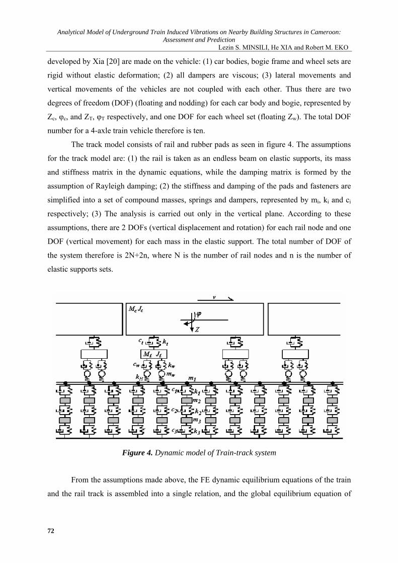
Analytical Model of Underground Train Induced Vibrations on Nearby Building Structures in Cameroon Assessment and Prediction
Lezin S MINSILI He XIA and Robert M EKO
developed by Xia [20] are made on the vehicle (1) car bodies bogie frame and wheel sets are
rigid without elastic deformation (2) all dampers are viscous (3) lateral movements and
vertical movements of the vehicles are not coupled with each other Thus there are two
degrees of freedom (DOF) (floating and nodding) for each car body and bogie represented by
Zc φc and ZT φT respectively and one DOF for each wheel set (floating Zw) The total DOF
number for a 4-axle train vehicle therefore is ten
The track model consists of rail and rubber pads as seen in figure 4 The assumptions
for the track model are (1) the rail is taken as an endless beam on elastic supports its mass
and stiffness matrix in the dynamic equations while the damping matrix is formed by the
assumption of Rayleigh damping (2) the stiffness and damping of the pads and fasteners are
simplified into a set of compound masses springs and dampers represented by mi ki and ci
respectively (3) The analysis is carried out only in the vertical plane According to these
assumptions there are 2 DOFs (vertical displacement and rotation) for each rail node and one
DOF (vertical movement) for each mass in the elastic support The total number of DOF of
the system therefore is 2N+2n where N is the number of rail nodes and n is the number of
elastic supports sets
Figure 4 Dynamic model of Train-track system
From the assumptions made above the FE dynamic equilibrium equations of the train
and the rail track is assembled into a single relation and the global equilibrium equation of
72
Leonardo Electronic Journal of Practices and Technologies
ISSN 1583-1078
Issue 23 July-December 2013
p 63-82
the train-rail track system is obtained as
)tx(FKZZCZM =++ (18)
Or in matrix form
⎪⎪⎭
⎪⎪⎬
⎫
⎪⎪⎩
⎪⎪⎨
⎧
=
⎪⎪⎭
⎪⎪⎬
⎫
⎪⎪⎩
⎪⎪⎨
⎧
⎥⎥⎥⎥
⎦
⎤
⎢⎢⎢⎢
⎣
⎡
+
⎪⎪⎭
⎪⎪⎬
⎫
⎪⎪⎩
⎪⎪⎨
⎧
⎥⎥⎥⎥
⎦
⎤
⎢⎢⎢⎢
⎣
⎡
+
⎪⎪⎭
⎪⎪⎬
⎫
⎪⎪⎩
⎪⎪⎨
⎧
⎥⎥⎥⎥
⎦
⎤
⎢⎢⎢⎢
⎣
⎡
n
2
1
n
2
1
n
2
1
n
2
1
n
2
1
n
2
1
n
2
1
F
FF
Z
ZZ
K00
0K000K
Z
ZZ
C00
0C000C
Z
ZZ
M00
0M000M
(19)
Where the wheel-rail contact force F(xt) is calculated using the Hertzian contact
theory by using the discrete form of the Train-rail track interaction along the rail axis given
as
[ ]sum δminusminusφ=k
51ijijwijHlijl )x()tx(vZkF (20)
where Zwj(t) = the wheel displacement v(xt) = the rail deflection at the wheel-rail contact
point δ(x) = the wheel or rail profile change kH = the Hertzian contact coefficient n = the
number of vehicles Mi = the mass matrix of the i-th vehicle (being a diagonal matrix we have
Diag Mi=[Mc Jc MT1 MT2 JT2 Mw1 hellip Mw4]) Ki = the vehicle stiffness matrix and Ci =
the damping matrix Zi is the vehicle displacement vector Fi is the force vector of the i-th
vehicle Mn Cn Kn are respectively the mass damping and the stiffness matrices of the track
are respectively the nodal acceleration velocity and displacement vectors as
given in the FE dynamic equation oslashij is the distributive coefficient of the j-th wheel-set to the
i-th rail node
vandvv
Simulation and Analysis of the TSS Interaction
Simulation by the FEM
The FEM is the most widely used numerical method implemented by researchers and
commercial software producers It can be used to solve complex geometries but it requires an
appropriate discrete form of the media being modelled This makes the FEM computationally
unfeasible for very large scale models such as those involving unbounded domains unless
substantial shortcuts are implemented These may entail the use of coarse elements low
frequency simulations or the introduction of boundary artefacts [21] This not being the case
73
Analytical Model of Underground Train Induced Vibrations on Nearby Building Structures in Cameroon Assessment and Prediction
Lezin S MINSILI He XIA and Robert M EKO
of the present work since the soil sub domain and the building sub domain are bounded with
appropriate boundary conditions as seen in the FE element model of the tunnel-soil-building
system shown in figure 5 assuming a 2-D plane strain state The double-track is inside the
single hollow tunnel with a dimension of 10m (height) times12m (width) and with 14m cover
depth The soil is divided into four layers with their parameters shown in Table 1 An 18-
story building is set at 30m from the tunnel centreline which has the pile foundation with
15m length and whose members are all simulated as beam elements
Figure 5 Finite element model of tunnel-soil-building system
Table 1 Parameters of the building and sub soils Materials Elastic modulus
[MPa] Poisson ratio Density
[Nmiddotm-3]Remarks
C30 Concrete 30000 018 2550 Beam (03mtimes06m) Columns (06mtimes06m)
Backfilling soil 29 040 17000 Arenaceous clay 1 127 033 18800 Moderate fine sand 136 037 20200 Arenaceous clay 2 77 028 20000
74
Leonardo Electronic Journal of Practices and Technologies
ISSN 1583-1078
Issue 23 July-December 2013
p 63-82
The vibration evaluation method is settled in accordance with ISO26311-1985 that
adopts the vertical acceleration level in terms of Lz=20log10(aa0) where a is transient
acceleration of the observation points with the unit of ms2 and a0 is the basic acceleration
with the value of 1times10-5ms2 Since the model is asymmetric the whole system must be
analyzed and the FE model should be as large as possible to contain the train length and to
reduce the effect of the wave reflection at the artificial border In this analysis the model
covers a dimension of 650mtimes80m The bottom is assumed to have fixed constraints and the
two sides are spring elements with the stiffness of 500kNm
The damping behaviour of each basic component j of the rail track-ground system was
modelled using the Rayleigh method The damping matrix C can be obtained from the
relation
KMC jjjj βα += (21)
where Mj and Kj are the j-th components of the mass and the stiffness matrices (respectively)
Determination of the parameters αj and βj (as example αj =004 and βj =001) was carried out
using the procedure described by Di Mino [22]
A train composed of 6 cars running on a track of continuous welded rails of 50 kgm is
considered The mass of concrete sleeper is 251 kg and the sleeper space is d=055m The
distributed rail spring stiffness is ks=20246 MNm2 and the wheel-rail contact stiffness
coefficient is kH=1421MNm Implementing the theory and model described above with the
vehicle and track parameters listed in table 2 the dynamic loads applied to the tunnel is
obtained as shown in figure 6
Table 2 Calculation parameters of underground vehicle Vehicle full length L(m) 1952Bogie centrelinesrsquo distance 2s(m) 1266Fixed axle spacing 2d(m) 230 Car body mass Mc(t) 37 Car mass moment of inertia Jc (t-m2) 1700 Bogie mass Mt(t) 360 Bogie mass moment of inertia Jt(t-m2) 962 Bogie spring stiffness Kt (kNm) 2080 Bogie damping coefficient Ct (kNsm) 240 Wheel set mass Mw (t) 170 Wheel spring stiffness (kNm) 2450 Wheel damping coefficient Kw (kNsm) 240
75
Analytical Model of Underground Train Induced Vibrations on Nearby Building Structures in Cameroon Assessment and Prediction
Lezin S MINSILI He XIA and Robert M EKO
a) Dynamic load of train-track system
b) The spectrum of the train-track dynamic load
Figure 6 Characteristics of the dynamic load applied to the tunnel
Analytical Results
The previous figures describe the calculated dynamic load and its frequency spectrum
when the train speed is 50 kmh which clearly show that the force is mainly induced by the
moving axle loads of vehicles and that the load mainly concentrates at the frequency range of
0 to 10Hz This load is adopted as the dynamic load for the next calculation
Figure 7 shows the distribution of ground vibrations at two locations perpendicular to
76
Leonardo Electronic Journal of Practices and Technologies
ISSN 1583-1078
Issue 23 July-December 2013
p 63-82
the tunnel centreline It can be seen that the maximum acceleration within the distance of 30m
(49cms2) is smaller than the maximum level at 0 m (81cms2) The difference between
computed acceleration time histories computed at these locations is due to the vibration
attenuation with distance This attenuation of the peak acceleration from 81 to 49 might be
dependent on the train speed and train loading the geotechnical conditions of the soil and
possibly to the frequency components of the train-track excitation loading that is filtered
throughout soil layers
a) at 0 m from the tunnel centreline
b) at 30 m from the tunnel centreline
Figure 7 Ground acceleration time histories
77
Analytical Model of Underground Train Induced Vibrations on Nearby Building Structures in Cameroon Assessment and Prediction
Lezin S MINSILI He XIA and Robert M EKO
The train still running at the speed of 50kmh the building acceleration time-histories
of the first floor the 8th floor and the top floor are illustrated in figure 8 It can be seen that
the form of acceleration amplitude changes at different floor With the present vibration
amplification of the maximal acceleration response from the first floor to the top floor level it
is obvious that the building structure generates energy with time increment what is easily
noticed at the first floor level in figure 8a
a) at the first floor
b) at the 8-th floor
Figure 8 The acceleration time history at different floor levels
78
Leonardo Electronic Journal of Practices and Technologies
ISSN 1583-1078
Issue 23 July-December 2013
p 63-82
c) at the top level
Figure 8 The acceleration time history at different floor levels
Many investigations support that in a structure under specific modal vibration some of
its parts or elements can be subjected to local resonance and even self-excitation Thus the
observed acceleration amplification from the 3-rd second in figure 8c is related to local
resonance From literature survey [16-17 23-26] it is known that there are no damages on a
building due to train induced ground-borne vibration even if human occupants of the
buildings might be seriously affected But the computed results from the given model shows
that there is the possibility for an underground train passing through an urban area under
specific sub-models described above to excite a particular building or some of its elements
with one of their natural frequencies thus creating the resonance problem Investigations on
this problem are still going on in the Department
Conclusions
The TSS presented in this paper is subdivided into three main sub-models the source
the propagation path and the receiver in order to study and understand the influence of factors
such as dynamic characteristics of the train the railway structure soil and building
characteristics on ground-born vibrations and their effects on nearby building structures
By dividing the TSS model into sub-models it is possible to replace some parts of the
model with data from a particular site if available Thus if a new railway is being designed
79
Analytical Model of Underground Train Induced Vibrations on Nearby Building Structures in Cameroon Assessment and Prediction
Lezin S MINSILI He XIA and Robert M EKO
close to a building a prediction with good accuracy can be made on the effects of the
anticipated railway on the building
With the limitations of available data on TSS interaction in Cameroon experiments
and measurements are still to be done at sites with different geotechnical conditions different
train-track models and different building types to validate obtained results and thus elucidate
these important facts
Acknowledgements
This paper is a continuation of the study presented at the ldquo3rd International Symposium
on Environmental Vibrations Prediction Monitoring Mitigation and Evaluationrdquo 2007
References
1 The World Bank Cameroon Upgrading Low Income Urban Settlements - Country
Assessment Report 2002 AFTU 1 amp 2 Available at
httpwebmiteduurbanupgradingupgradingcase-examplesoverview-africacountry-
assessmentsdownloadCAMEROONpdf (accessed 08062013)
2 NRMP The National Railway Network Master Plan in Cameroon Final report of the
prefeasibility study conducted by KORPEC (KORea Port Engineering Corporation) and
Validated by the Government of Cameroon 2012 p 390-402
3 Du XT Xu Y L Xia H Dynamic interaction of bridgendashtrain system under non-
uniform seismic ground motion Earthquake Engineering Structural Dynamics 2012
41 p 139-157 DOI 101002eqe1122
4 Rodriacuteguez-Tembleque L Abascal R A 3D FEMndashBEM Rolling Contact Formulation
for Unstructured Meshes International Journal of Solids and Structures 2010 47 p
330-353 Available at
httpwwwsciencedirectcomsciencearticlepiiS0020768309003953 (accessed
08062013)
5 Zolghadr Jahromi H Izzuddin BA Zdravkovic L Partitioned analysis of nonlinear
80
Leonardo Electronic Journal of Practices and Technologies
ISSN 1583-1078
Issue 23 July-December 2013
p 63-82
soil-structure interaction using iterative coupling Interaction and Multiscale
Mechanics 2007 1(1) p 33-51
6 Xia H Dynamic Interaction of Vehicles and Structures Science Press Beijing China
2002
7 Chore HS Ingle RK Sawant VA Building frame - pile foundation - soil interaction
analysis a parametric study Interaction and Multiscale Mechanics 2010 3(1) p 55-
79
8 Krylov VV Effects of track properties on ground vibrations generated by high-speed
trains ACUSTICA-Acta Acustica 1998 84(1) p 78-90
9 Daumueller AN Jauregui DV Strain-Based Evaluation of a Steel Through-Girder
Railroad Bridge Hindawi Publishing Corporation Advances in Civil Engineering
2012 Available at httpwwwhindawicomjournalsamseai(accessed 17062013)
10 Xiaoyan L Numerical Analysis of Track Structures in Railway Beijing China Railway
Press 1998
11 Grassie SL Gregory RW Dynamic response of railway track to high frequency
vertical excitation Journal of Mechanical Engineering Science 1982 24(2) p 77-90
12 Flyacuteba L Vibration of Solids and Structures Under Moving Loads London Thomas
Telford 1999
13 Weitsman Y On foundations that react in compression only Journal of Applied
Mechanics 1970 12 p 1019-1030
14 Wang K Liu P Lateral Stability Analysis of Heavy-Haul Vehicle on Curved Track
Based on WheelRail Coupled Dynamics Journal of Transportation Technologies 2012
2(2) p 150-157 Available at httpwwwSciRPorgjournaljtts (accessed 08062013)
15 Woods RD Screening of Surface Waves in Soils Journal of Soil Mechanics and
Foundation Division Proceedings of the ASCE 1968
16 Woods RD Larry PJ Energy-Attenuation Relationships from Construction
Vibrations Vibration Problems in Geotechnical Engineering ASCE Proceedings
Detroit Michigan 1985
17 Eisenman J Deischl F Structure-Borne Sound from Underground Railway Systems
81
Analytical Model of Underground Train Induced Vibrations on Nearby Building Structures in Cameroon Assessment and Prediction
Lezin S MINSILI He XIA and Robert M EKO
82
Der Eisenbahningenieur 1986 3 p 101-110
18 Alshawi M Underwood J Improving the constructability of design solutions through
an integrated system Journal of Engineering Construction and Architectural
Management 1993 3(1amp2) p 47ndash67 doi101108eb021022
19 Patrick C Low Vibration and Noise Track Systems with Tunable Properties for Modern
LRTStreetcar Track on Surface in Urban Areas TIVCrsquo2001 International Symposium
on Traffic Induced Vibrations amp Controls Beijing China 2001 p 161-176
20 Xia H Cao YM Zhang N Numerical Analysis of Vibration Effects of Metro Trains
on Surrounding Environment Int J of Structural Stability and Dynamics 2007 7 p
45-56
21 Le Kouby A Bourgeois E Rocher-Lacoste F Subgrade Improvement Method for
Existing Railway Lines ndash an Experimental and Numerical Study Electronic Journal of
Geotechnical Engineering 2010 15 p461-494
22 Di Mino G Di Liberto CM Nigrelli J A FEM model of rail track-ground system to
calculate the ground borne vibrations a case of rail track with wooden sleepers and k-
fastenings at Castelvetrano Advanced Characterisation of Pavement and Soil
Engineering Materials Athens Greece 2007 p 1737-1752
23 Chauhan HM Pomal MM Bhuta GN A Comparative Study Of Wind Forces On
High-Rise Buildings as Per Is 875-Iii (1987) and Proposed Draft Code (2011) GRA -
Global Research Analysis 2013 2(5) p 59-60
24 Lei X Zhang B Influence of track stiffness distribution on vehicle and track
interactions in track transition Proceedings of the Institution of Mechanical Engineers
Part F Journal of Rail and Rapid Transit 2010 224592 p 592-604 Available at
httppifsagepubcomcontent2246592 (accessed 28082012)
25 Thorat YV Kadam SS Design and Development of Test Setup for VibrationAnalysis
with Soft Foot Indian Journal of Applied Research 2012 2(3) p 59-62
26 Xiaojing Sun Weining Liu Dawen Xie Yingxuan Jia Vibration impacts on adjacent
sensitive buildings induced by metro trains World Tunnel Congress 2008 -
Underground Facilities for Better Environment and Safety ndash India Agra 2008 p 1382-
1389

Leonardo Electronic Journal of Practices and Technologies
ISSN 1583-1078
Issue 23 July-December 2013
p 63-82
the train-rail track system is obtained as
)tx(FKZZCZM =++ (18)
Or in matrix form
⎪⎪⎭
⎪⎪⎬
⎫
⎪⎪⎩
⎪⎪⎨
⎧
=
⎪⎪⎭
⎪⎪⎬
⎫
⎪⎪⎩
⎪⎪⎨
⎧
⎥⎥⎥⎥
⎦
⎤
⎢⎢⎢⎢
⎣
⎡
+
⎪⎪⎭
⎪⎪⎬
⎫
⎪⎪⎩
⎪⎪⎨
⎧
⎥⎥⎥⎥
⎦
⎤
⎢⎢⎢⎢
⎣
⎡
+
⎪⎪⎭
⎪⎪⎬
⎫
⎪⎪⎩
⎪⎪⎨
⎧
⎥⎥⎥⎥
⎦
⎤
⎢⎢⎢⎢
⎣
⎡
n
2
1
n
2
1
n
2
1
n
2
1
n
2
1
n
2
1
n
2
1
F
FF
Z
ZZ
K00
0K000K
Z
ZZ
C00
0C000C
Z
ZZ
M00
0M000M
(19)
Where the wheel-rail contact force F(xt) is calculated using the Hertzian contact
theory by using the discrete form of the Train-rail track interaction along the rail axis given
as
[ ]sum δminusminusφ=k
51ijijwijHlijl )x()tx(vZkF (20)
where Zwj(t) = the wheel displacement v(xt) = the rail deflection at the wheel-rail contact
point δ(x) = the wheel or rail profile change kH = the Hertzian contact coefficient n = the
number of vehicles Mi = the mass matrix of the i-th vehicle (being a diagonal matrix we have
Diag Mi=[Mc Jc MT1 MT2 JT2 Mw1 hellip Mw4]) Ki = the vehicle stiffness matrix and Ci =
the damping matrix Zi is the vehicle displacement vector Fi is the force vector of the i-th
vehicle Mn Cn Kn are respectively the mass damping and the stiffness matrices of the track
are respectively the nodal acceleration velocity and displacement vectors as
given in the FE dynamic equation oslashij is the distributive coefficient of the j-th wheel-set to the
i-th rail node
vandvv
Simulation and Analysis of the TSS Interaction
Simulation by the FEM
The FEM is the most widely used numerical method implemented by researchers and
commercial software producers It can be used to solve complex geometries but it requires an
appropriate discrete form of the media being modelled This makes the FEM computationally
unfeasible for very large scale models such as those involving unbounded domains unless
substantial shortcuts are implemented These may entail the use of coarse elements low
frequency simulations or the introduction of boundary artefacts [21] This not being the case
73
Analytical Model of Underground Train Induced Vibrations on Nearby Building Structures in Cameroon Assessment and Prediction
Lezin S MINSILI He XIA and Robert M EKO
of the present work since the soil sub domain and the building sub domain are bounded with
appropriate boundary conditions as seen in the FE element model of the tunnel-soil-building
system shown in figure 5 assuming a 2-D plane strain state The double-track is inside the
single hollow tunnel with a dimension of 10m (height) times12m (width) and with 14m cover
depth The soil is divided into four layers with their parameters shown in Table 1 An 18-
story building is set at 30m from the tunnel centreline which has the pile foundation with
15m length and whose members are all simulated as beam elements
Figure 5 Finite element model of tunnel-soil-building system
Table 1 Parameters of the building and sub soils Materials Elastic modulus
[MPa] Poisson ratio Density
[Nmiddotm-3]Remarks
C30 Concrete 30000 018 2550 Beam (03mtimes06m) Columns (06mtimes06m)
Backfilling soil 29 040 17000 Arenaceous clay 1 127 033 18800 Moderate fine sand 136 037 20200 Arenaceous clay 2 77 028 20000
74
Leonardo Electronic Journal of Practices and Technologies
ISSN 1583-1078
Issue 23 July-December 2013
p 63-82
The vibration evaluation method is settled in accordance with ISO26311-1985 that
adopts the vertical acceleration level in terms of Lz=20log10(aa0) where a is transient
acceleration of the observation points with the unit of ms2 and a0 is the basic acceleration
with the value of 1times10-5ms2 Since the model is asymmetric the whole system must be
analyzed and the FE model should be as large as possible to contain the train length and to
reduce the effect of the wave reflection at the artificial border In this analysis the model
covers a dimension of 650mtimes80m The bottom is assumed to have fixed constraints and the
two sides are spring elements with the stiffness of 500kNm
The damping behaviour of each basic component j of the rail track-ground system was
modelled using the Rayleigh method The damping matrix C can be obtained from the
relation
KMC jjjj βα += (21)
where Mj and Kj are the j-th components of the mass and the stiffness matrices (respectively)
Determination of the parameters αj and βj (as example αj =004 and βj =001) was carried out
using the procedure described by Di Mino [22]
A train composed of 6 cars running on a track of continuous welded rails of 50 kgm is
considered The mass of concrete sleeper is 251 kg and the sleeper space is d=055m The
distributed rail spring stiffness is ks=20246 MNm2 and the wheel-rail contact stiffness
coefficient is kH=1421MNm Implementing the theory and model described above with the
vehicle and track parameters listed in table 2 the dynamic loads applied to the tunnel is
obtained as shown in figure 6
Table 2 Calculation parameters of underground vehicle Vehicle full length L(m) 1952Bogie centrelinesrsquo distance 2s(m) 1266Fixed axle spacing 2d(m) 230 Car body mass Mc(t) 37 Car mass moment of inertia Jc (t-m2) 1700 Bogie mass Mt(t) 360 Bogie mass moment of inertia Jt(t-m2) 962 Bogie spring stiffness Kt (kNm) 2080 Bogie damping coefficient Ct (kNsm) 240 Wheel set mass Mw (t) 170 Wheel spring stiffness (kNm) 2450 Wheel damping coefficient Kw (kNsm) 240
75
Analytical Model of Underground Train Induced Vibrations on Nearby Building Structures in Cameroon Assessment and Prediction
Lezin S MINSILI He XIA and Robert M EKO
a) Dynamic load of train-track system
b) The spectrum of the train-track dynamic load
Figure 6 Characteristics of the dynamic load applied to the tunnel
Analytical Results
The previous figures describe the calculated dynamic load and its frequency spectrum
when the train speed is 50 kmh which clearly show that the force is mainly induced by the
moving axle loads of vehicles and that the load mainly concentrates at the frequency range of
0 to 10Hz This load is adopted as the dynamic load for the next calculation
Figure 7 shows the distribution of ground vibrations at two locations perpendicular to
76
Leonardo Electronic Journal of Practices and Technologies
ISSN 1583-1078
Issue 23 July-December 2013
p 63-82
the tunnel centreline It can be seen that the maximum acceleration within the distance of 30m
(49cms2) is smaller than the maximum level at 0 m (81cms2) The difference between
computed acceleration time histories computed at these locations is due to the vibration
attenuation with distance This attenuation of the peak acceleration from 81 to 49 might be
dependent on the train speed and train loading the geotechnical conditions of the soil and
possibly to the frequency components of the train-track excitation loading that is filtered
throughout soil layers
a) at 0 m from the tunnel centreline
b) at 30 m from the tunnel centreline
Figure 7 Ground acceleration time histories
77
Analytical Model of Underground Train Induced Vibrations on Nearby Building Structures in Cameroon Assessment and Prediction
Lezin S MINSILI He XIA and Robert M EKO
The train still running at the speed of 50kmh the building acceleration time-histories
of the first floor the 8th floor and the top floor are illustrated in figure 8 It can be seen that
the form of acceleration amplitude changes at different floor With the present vibration
amplification of the maximal acceleration response from the first floor to the top floor level it
is obvious that the building structure generates energy with time increment what is easily
noticed at the first floor level in figure 8a
a) at the first floor
b) at the 8-th floor
Figure 8 The acceleration time history at different floor levels
78
Leonardo Electronic Journal of Practices and Technologies
ISSN 1583-1078
Issue 23 July-December 2013
p 63-82
c) at the top level
Figure 8 The acceleration time history at different floor levels
Many investigations support that in a structure under specific modal vibration some of
its parts or elements can be subjected to local resonance and even self-excitation Thus the
observed acceleration amplification from the 3-rd second in figure 8c is related to local
resonance From literature survey [16-17 23-26] it is known that there are no damages on a
building due to train induced ground-borne vibration even if human occupants of the
buildings might be seriously affected But the computed results from the given model shows
that there is the possibility for an underground train passing through an urban area under
specific sub-models described above to excite a particular building or some of its elements
with one of their natural frequencies thus creating the resonance problem Investigations on
this problem are still going on in the Department
Conclusions
The TSS presented in this paper is subdivided into three main sub-models the source
the propagation path and the receiver in order to study and understand the influence of factors
such as dynamic characteristics of the train the railway structure soil and building
characteristics on ground-born vibrations and their effects on nearby building structures
By dividing the TSS model into sub-models it is possible to replace some parts of the
model with data from a particular site if available Thus if a new railway is being designed
79
Analytical Model of Underground Train Induced Vibrations on Nearby Building Structures in Cameroon Assessment and Prediction
Lezin S MINSILI He XIA and Robert M EKO
close to a building a prediction with good accuracy can be made on the effects of the
anticipated railway on the building
With the limitations of available data on TSS interaction in Cameroon experiments
and measurements are still to be done at sites with different geotechnical conditions different
train-track models and different building types to validate obtained results and thus elucidate
these important facts
Acknowledgements
This paper is a continuation of the study presented at the ldquo3rd International Symposium
on Environmental Vibrations Prediction Monitoring Mitigation and Evaluationrdquo 2007
References
1 The World Bank Cameroon Upgrading Low Income Urban Settlements - Country
Assessment Report 2002 AFTU 1 amp 2 Available at
httpwebmiteduurbanupgradingupgradingcase-examplesoverview-africacountry-
assessmentsdownloadCAMEROONpdf (accessed 08062013)
2 NRMP The National Railway Network Master Plan in Cameroon Final report of the
prefeasibility study conducted by KORPEC (KORea Port Engineering Corporation) and
Validated by the Government of Cameroon 2012 p 390-402
3 Du XT Xu Y L Xia H Dynamic interaction of bridgendashtrain system under non-
uniform seismic ground motion Earthquake Engineering Structural Dynamics 2012
41 p 139-157 DOI 101002eqe1122
4 Rodriacuteguez-Tembleque L Abascal R A 3D FEMndashBEM Rolling Contact Formulation
for Unstructured Meshes International Journal of Solids and Structures 2010 47 p
330-353 Available at
httpwwwsciencedirectcomsciencearticlepiiS0020768309003953 (accessed
08062013)
5 Zolghadr Jahromi H Izzuddin BA Zdravkovic L Partitioned analysis of nonlinear
80
Leonardo Electronic Journal of Practices and Technologies
ISSN 1583-1078
Issue 23 July-December 2013
p 63-82
soil-structure interaction using iterative coupling Interaction and Multiscale
Mechanics 2007 1(1) p 33-51
6 Xia H Dynamic Interaction of Vehicles and Structures Science Press Beijing China
2002
7 Chore HS Ingle RK Sawant VA Building frame - pile foundation - soil interaction
analysis a parametric study Interaction and Multiscale Mechanics 2010 3(1) p 55-
79
8 Krylov VV Effects of track properties on ground vibrations generated by high-speed
trains ACUSTICA-Acta Acustica 1998 84(1) p 78-90
9 Daumueller AN Jauregui DV Strain-Based Evaluation of a Steel Through-Girder
Railroad Bridge Hindawi Publishing Corporation Advances in Civil Engineering
2012 Available at httpwwwhindawicomjournalsamseai(accessed 17062013)
10 Xiaoyan L Numerical Analysis of Track Structures in Railway Beijing China Railway
Press 1998
11 Grassie SL Gregory RW Dynamic response of railway track to high frequency
vertical excitation Journal of Mechanical Engineering Science 1982 24(2) p 77-90
12 Flyacuteba L Vibration of Solids and Structures Under Moving Loads London Thomas
Telford 1999
13 Weitsman Y On foundations that react in compression only Journal of Applied
Mechanics 1970 12 p 1019-1030
14 Wang K Liu P Lateral Stability Analysis of Heavy-Haul Vehicle on Curved Track
Based on WheelRail Coupled Dynamics Journal of Transportation Technologies 2012
2(2) p 150-157 Available at httpwwwSciRPorgjournaljtts (accessed 08062013)
15 Woods RD Screening of Surface Waves in Soils Journal of Soil Mechanics and
Foundation Division Proceedings of the ASCE 1968
16 Woods RD Larry PJ Energy-Attenuation Relationships from Construction
Vibrations Vibration Problems in Geotechnical Engineering ASCE Proceedings
Detroit Michigan 1985
17 Eisenman J Deischl F Structure-Borne Sound from Underground Railway Systems
81
Analytical Model of Underground Train Induced Vibrations on Nearby Building Structures in Cameroon Assessment and Prediction
Lezin S MINSILI He XIA and Robert M EKO
82
Der Eisenbahningenieur 1986 3 p 101-110
18 Alshawi M Underwood J Improving the constructability of design solutions through
an integrated system Journal of Engineering Construction and Architectural
Management 1993 3(1amp2) p 47ndash67 doi101108eb021022
19 Patrick C Low Vibration and Noise Track Systems with Tunable Properties for Modern
LRTStreetcar Track on Surface in Urban Areas TIVCrsquo2001 International Symposium
on Traffic Induced Vibrations amp Controls Beijing China 2001 p 161-176
20 Xia H Cao YM Zhang N Numerical Analysis of Vibration Effects of Metro Trains
on Surrounding Environment Int J of Structural Stability and Dynamics 2007 7 p
45-56
21 Le Kouby A Bourgeois E Rocher-Lacoste F Subgrade Improvement Method for
Existing Railway Lines ndash an Experimental and Numerical Study Electronic Journal of
Geotechnical Engineering 2010 15 p461-494
22 Di Mino G Di Liberto CM Nigrelli J A FEM model of rail track-ground system to
calculate the ground borne vibrations a case of rail track with wooden sleepers and k-
fastenings at Castelvetrano Advanced Characterisation of Pavement and Soil
Engineering Materials Athens Greece 2007 p 1737-1752
23 Chauhan HM Pomal MM Bhuta GN A Comparative Study Of Wind Forces On
High-Rise Buildings as Per Is 875-Iii (1987) and Proposed Draft Code (2011) GRA -
Global Research Analysis 2013 2(5) p 59-60
24 Lei X Zhang B Influence of track stiffness distribution on vehicle and track
interactions in track transition Proceedings of the Institution of Mechanical Engineers
Part F Journal of Rail and Rapid Transit 2010 224592 p 592-604 Available at
httppifsagepubcomcontent2246592 (accessed 28082012)
25 Thorat YV Kadam SS Design and Development of Test Setup for VibrationAnalysis
with Soft Foot Indian Journal of Applied Research 2012 2(3) p 59-62
26 Xiaojing Sun Weining Liu Dawen Xie Yingxuan Jia Vibration impacts on adjacent
sensitive buildings induced by metro trains World Tunnel Congress 2008 -
Underground Facilities for Better Environment and Safety ndash India Agra 2008 p 1382-
1389

Analytical Model of Underground Train Induced Vibrations on Nearby Building Structures in Cameroon Assessment and Prediction
Lezin S MINSILI He XIA and Robert M EKO
of the present work since the soil sub domain and the building sub domain are bounded with
appropriate boundary conditions as seen in the FE element model of the tunnel-soil-building
system shown in figure 5 assuming a 2-D plane strain state The double-track is inside the
single hollow tunnel with a dimension of 10m (height) times12m (width) and with 14m cover
depth The soil is divided into four layers with their parameters shown in Table 1 An 18-
story building is set at 30m from the tunnel centreline which has the pile foundation with
15m length and whose members are all simulated as beam elements
Figure 5 Finite element model of tunnel-soil-building system
Table 1 Parameters of the building and sub soils Materials Elastic modulus
[MPa] Poisson ratio Density
[Nmiddotm-3]Remarks
C30 Concrete 30000 018 2550 Beam (03mtimes06m) Columns (06mtimes06m)
Backfilling soil 29 040 17000 Arenaceous clay 1 127 033 18800 Moderate fine sand 136 037 20200 Arenaceous clay 2 77 028 20000
74
Leonardo Electronic Journal of Practices and Technologies
ISSN 1583-1078
Issue 23 July-December 2013
p 63-82
The vibration evaluation method is settled in accordance with ISO26311-1985 that
adopts the vertical acceleration level in terms of Lz=20log10(aa0) where a is transient
acceleration of the observation points with the unit of ms2 and a0 is the basic acceleration
with the value of 1times10-5ms2 Since the model is asymmetric the whole system must be
analyzed and the FE model should be as large as possible to contain the train length and to
reduce the effect of the wave reflection at the artificial border In this analysis the model
covers a dimension of 650mtimes80m The bottom is assumed to have fixed constraints and the
two sides are spring elements with the stiffness of 500kNm
The damping behaviour of each basic component j of the rail track-ground system was
modelled using the Rayleigh method The damping matrix C can be obtained from the
relation
KMC jjjj βα += (21)
where Mj and Kj are the j-th components of the mass and the stiffness matrices (respectively)
Determination of the parameters αj and βj (as example αj =004 and βj =001) was carried out
using the procedure described by Di Mino [22]
A train composed of 6 cars running on a track of continuous welded rails of 50 kgm is
considered The mass of concrete sleeper is 251 kg and the sleeper space is d=055m The
distributed rail spring stiffness is ks=20246 MNm2 and the wheel-rail contact stiffness
coefficient is kH=1421MNm Implementing the theory and model described above with the
vehicle and track parameters listed in table 2 the dynamic loads applied to the tunnel is
obtained as shown in figure 6
Table 2 Calculation parameters of underground vehicle Vehicle full length L(m) 1952Bogie centrelinesrsquo distance 2s(m) 1266Fixed axle spacing 2d(m) 230 Car body mass Mc(t) 37 Car mass moment of inertia Jc (t-m2) 1700 Bogie mass Mt(t) 360 Bogie mass moment of inertia Jt(t-m2) 962 Bogie spring stiffness Kt (kNm) 2080 Bogie damping coefficient Ct (kNsm) 240 Wheel set mass Mw (t) 170 Wheel spring stiffness (kNm) 2450 Wheel damping coefficient Kw (kNsm) 240
75
Analytical Model of Underground Train Induced Vibrations on Nearby Building Structures in Cameroon Assessment and Prediction
Lezin S MINSILI He XIA and Robert M EKO
a) Dynamic load of train-track system
b) The spectrum of the train-track dynamic load
Figure 6 Characteristics of the dynamic load applied to the tunnel
Analytical Results
The previous figures describe the calculated dynamic load and its frequency spectrum
when the train speed is 50 kmh which clearly show that the force is mainly induced by the
moving axle loads of vehicles and that the load mainly concentrates at the frequency range of
0 to 10Hz This load is adopted as the dynamic load for the next calculation
Figure 7 shows the distribution of ground vibrations at two locations perpendicular to
76
Leonardo Electronic Journal of Practices and Technologies
ISSN 1583-1078
Issue 23 July-December 2013
p 63-82
the tunnel centreline It can be seen that the maximum acceleration within the distance of 30m
(49cms2) is smaller than the maximum level at 0 m (81cms2) The difference between
computed acceleration time histories computed at these locations is due to the vibration
attenuation with distance This attenuation of the peak acceleration from 81 to 49 might be
dependent on the train speed and train loading the geotechnical conditions of the soil and
possibly to the frequency components of the train-track excitation loading that is filtered
throughout soil layers
a) at 0 m from the tunnel centreline
b) at 30 m from the tunnel centreline
Figure 7 Ground acceleration time histories
77
Analytical Model of Underground Train Induced Vibrations on Nearby Building Structures in Cameroon Assessment and Prediction
Lezin S MINSILI He XIA and Robert M EKO
The train still running at the speed of 50kmh the building acceleration time-histories
of the first floor the 8th floor and the top floor are illustrated in figure 8 It can be seen that
the form of acceleration amplitude changes at different floor With the present vibration
amplification of the maximal acceleration response from the first floor to the top floor level it
is obvious that the building structure generates energy with time increment what is easily
noticed at the first floor level in figure 8a
a) at the first floor
b) at the 8-th floor
Figure 8 The acceleration time history at different floor levels
78
Leonardo Electronic Journal of Practices and Technologies
ISSN 1583-1078
Issue 23 July-December 2013
p 63-82
c) at the top level
Figure 8 The acceleration time history at different floor levels
Many investigations support that in a structure under specific modal vibration some of
its parts or elements can be subjected to local resonance and even self-excitation Thus the
observed acceleration amplification from the 3-rd second in figure 8c is related to local
resonance From literature survey [16-17 23-26] it is known that there are no damages on a
building due to train induced ground-borne vibration even if human occupants of the
buildings might be seriously affected But the computed results from the given model shows
that there is the possibility for an underground train passing through an urban area under
specific sub-models described above to excite a particular building or some of its elements
with one of their natural frequencies thus creating the resonance problem Investigations on
this problem are still going on in the Department
Conclusions
The TSS presented in this paper is subdivided into three main sub-models the source
the propagation path and the receiver in order to study and understand the influence of factors
such as dynamic characteristics of the train the railway structure soil and building
characteristics on ground-born vibrations and their effects on nearby building structures
By dividing the TSS model into sub-models it is possible to replace some parts of the
model with data from a particular site if available Thus if a new railway is being designed
79
Analytical Model of Underground Train Induced Vibrations on Nearby Building Structures in Cameroon Assessment and Prediction
Lezin S MINSILI He XIA and Robert M EKO
close to a building a prediction with good accuracy can be made on the effects of the
anticipated railway on the building
With the limitations of available data on TSS interaction in Cameroon experiments
and measurements are still to be done at sites with different geotechnical conditions different
train-track models and different building types to validate obtained results and thus elucidate
these important facts
Acknowledgements
This paper is a continuation of the study presented at the ldquo3rd International Symposium
on Environmental Vibrations Prediction Monitoring Mitigation and Evaluationrdquo 2007
References
1 The World Bank Cameroon Upgrading Low Income Urban Settlements - Country
Assessment Report 2002 AFTU 1 amp 2 Available at
httpwebmiteduurbanupgradingupgradingcase-examplesoverview-africacountry-
assessmentsdownloadCAMEROONpdf (accessed 08062013)
2 NRMP The National Railway Network Master Plan in Cameroon Final report of the
prefeasibility study conducted by KORPEC (KORea Port Engineering Corporation) and
Validated by the Government of Cameroon 2012 p 390-402
3 Du XT Xu Y L Xia H Dynamic interaction of bridgendashtrain system under non-
uniform seismic ground motion Earthquake Engineering Structural Dynamics 2012
41 p 139-157 DOI 101002eqe1122
4 Rodriacuteguez-Tembleque L Abascal R A 3D FEMndashBEM Rolling Contact Formulation
for Unstructured Meshes International Journal of Solids and Structures 2010 47 p
330-353 Available at
httpwwwsciencedirectcomsciencearticlepiiS0020768309003953 (accessed
08062013)
5 Zolghadr Jahromi H Izzuddin BA Zdravkovic L Partitioned analysis of nonlinear
80
Leonardo Electronic Journal of Practices and Technologies
ISSN 1583-1078
Issue 23 July-December 2013
p 63-82
soil-structure interaction using iterative coupling Interaction and Multiscale
Mechanics 2007 1(1) p 33-51
6 Xia H Dynamic Interaction of Vehicles and Structures Science Press Beijing China
2002
7 Chore HS Ingle RK Sawant VA Building frame - pile foundation - soil interaction
analysis a parametric study Interaction and Multiscale Mechanics 2010 3(1) p 55-
79
8 Krylov VV Effects of track properties on ground vibrations generated by high-speed
trains ACUSTICA-Acta Acustica 1998 84(1) p 78-90
9 Daumueller AN Jauregui DV Strain-Based Evaluation of a Steel Through-Girder
Railroad Bridge Hindawi Publishing Corporation Advances in Civil Engineering
2012 Available at httpwwwhindawicomjournalsamseai(accessed 17062013)
10 Xiaoyan L Numerical Analysis of Track Structures in Railway Beijing China Railway
Press 1998
11 Grassie SL Gregory RW Dynamic response of railway track to high frequency
vertical excitation Journal of Mechanical Engineering Science 1982 24(2) p 77-90
12 Flyacuteba L Vibration of Solids and Structures Under Moving Loads London Thomas
Telford 1999
13 Weitsman Y On foundations that react in compression only Journal of Applied
Mechanics 1970 12 p 1019-1030
14 Wang K Liu P Lateral Stability Analysis of Heavy-Haul Vehicle on Curved Track
Based on WheelRail Coupled Dynamics Journal of Transportation Technologies 2012
2(2) p 150-157 Available at httpwwwSciRPorgjournaljtts (accessed 08062013)
15 Woods RD Screening of Surface Waves in Soils Journal of Soil Mechanics and
Foundation Division Proceedings of the ASCE 1968
16 Woods RD Larry PJ Energy-Attenuation Relationships from Construction
Vibrations Vibration Problems in Geotechnical Engineering ASCE Proceedings
Detroit Michigan 1985
17 Eisenman J Deischl F Structure-Borne Sound from Underground Railway Systems
81
Analytical Model of Underground Train Induced Vibrations on Nearby Building Structures in Cameroon Assessment and Prediction
Lezin S MINSILI He XIA and Robert M EKO
82
Der Eisenbahningenieur 1986 3 p 101-110
18 Alshawi M Underwood J Improving the constructability of design solutions through
an integrated system Journal of Engineering Construction and Architectural
Management 1993 3(1amp2) p 47ndash67 doi101108eb021022
19 Patrick C Low Vibration and Noise Track Systems with Tunable Properties for Modern
LRTStreetcar Track on Surface in Urban Areas TIVCrsquo2001 International Symposium
on Traffic Induced Vibrations amp Controls Beijing China 2001 p 161-176
20 Xia H Cao YM Zhang N Numerical Analysis of Vibration Effects of Metro Trains
on Surrounding Environment Int J of Structural Stability and Dynamics 2007 7 p
45-56
21 Le Kouby A Bourgeois E Rocher-Lacoste F Subgrade Improvement Method for
Existing Railway Lines ndash an Experimental and Numerical Study Electronic Journal of
Geotechnical Engineering 2010 15 p461-494
22 Di Mino G Di Liberto CM Nigrelli J A FEM model of rail track-ground system to
calculate the ground borne vibrations a case of rail track with wooden sleepers and k-
fastenings at Castelvetrano Advanced Characterisation of Pavement and Soil
Engineering Materials Athens Greece 2007 p 1737-1752
23 Chauhan HM Pomal MM Bhuta GN A Comparative Study Of Wind Forces On
High-Rise Buildings as Per Is 875-Iii (1987) and Proposed Draft Code (2011) GRA -
Global Research Analysis 2013 2(5) p 59-60
24 Lei X Zhang B Influence of track stiffness distribution on vehicle and track
interactions in track transition Proceedings of the Institution of Mechanical Engineers
Part F Journal of Rail and Rapid Transit 2010 224592 p 592-604 Available at
httppifsagepubcomcontent2246592 (accessed 28082012)
25 Thorat YV Kadam SS Design and Development of Test Setup for VibrationAnalysis
with Soft Foot Indian Journal of Applied Research 2012 2(3) p 59-62
26 Xiaojing Sun Weining Liu Dawen Xie Yingxuan Jia Vibration impacts on adjacent
sensitive buildings induced by metro trains World Tunnel Congress 2008 -
Underground Facilities for Better Environment and Safety ndash India Agra 2008 p 1382-
1389
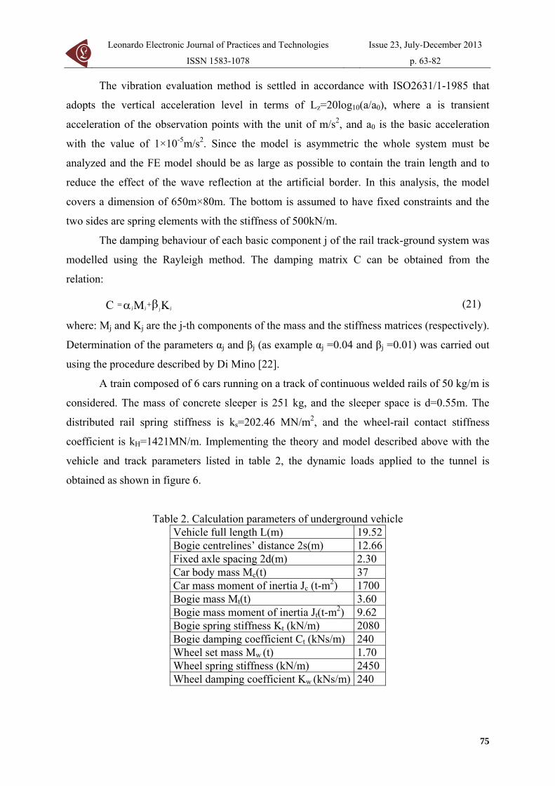
Leonardo Electronic Journal of Practices and Technologies
ISSN 1583-1078
Issue 23 July-December 2013
p 63-82
The vibration evaluation method is settled in accordance with ISO26311-1985 that
adopts the vertical acceleration level in terms of Lz=20log10(aa0) where a is transient
acceleration of the observation points with the unit of ms2 and a0 is the basic acceleration
with the value of 1times10-5ms2 Since the model is asymmetric the whole system must be
analyzed and the FE model should be as large as possible to contain the train length and to
reduce the effect of the wave reflection at the artificial border In this analysis the model
covers a dimension of 650mtimes80m The bottom is assumed to have fixed constraints and the
two sides are spring elements with the stiffness of 500kNm
The damping behaviour of each basic component j of the rail track-ground system was
modelled using the Rayleigh method The damping matrix C can be obtained from the
relation
KMC jjjj βα += (21)
where Mj and Kj are the j-th components of the mass and the stiffness matrices (respectively)
Determination of the parameters αj and βj (as example αj =004 and βj =001) was carried out
using the procedure described by Di Mino [22]
A train composed of 6 cars running on a track of continuous welded rails of 50 kgm is
considered The mass of concrete sleeper is 251 kg and the sleeper space is d=055m The
distributed rail spring stiffness is ks=20246 MNm2 and the wheel-rail contact stiffness
coefficient is kH=1421MNm Implementing the theory and model described above with the
vehicle and track parameters listed in table 2 the dynamic loads applied to the tunnel is
obtained as shown in figure 6
Table 2 Calculation parameters of underground vehicle Vehicle full length L(m) 1952Bogie centrelinesrsquo distance 2s(m) 1266Fixed axle spacing 2d(m) 230 Car body mass Mc(t) 37 Car mass moment of inertia Jc (t-m2) 1700 Bogie mass Mt(t) 360 Bogie mass moment of inertia Jt(t-m2) 962 Bogie spring stiffness Kt (kNm) 2080 Bogie damping coefficient Ct (kNsm) 240 Wheel set mass Mw (t) 170 Wheel spring stiffness (kNm) 2450 Wheel damping coefficient Kw (kNsm) 240
75
Analytical Model of Underground Train Induced Vibrations on Nearby Building Structures in Cameroon Assessment and Prediction
Lezin S MINSILI He XIA and Robert M EKO
a) Dynamic load of train-track system
b) The spectrum of the train-track dynamic load
Figure 6 Characteristics of the dynamic load applied to the tunnel
Analytical Results
The previous figures describe the calculated dynamic load and its frequency spectrum
when the train speed is 50 kmh which clearly show that the force is mainly induced by the
moving axle loads of vehicles and that the load mainly concentrates at the frequency range of
0 to 10Hz This load is adopted as the dynamic load for the next calculation
Figure 7 shows the distribution of ground vibrations at two locations perpendicular to
76
Leonardo Electronic Journal of Practices and Technologies
ISSN 1583-1078
Issue 23 July-December 2013
p 63-82
the tunnel centreline It can be seen that the maximum acceleration within the distance of 30m
(49cms2) is smaller than the maximum level at 0 m (81cms2) The difference between
computed acceleration time histories computed at these locations is due to the vibration
attenuation with distance This attenuation of the peak acceleration from 81 to 49 might be
dependent on the train speed and train loading the geotechnical conditions of the soil and
possibly to the frequency components of the train-track excitation loading that is filtered
throughout soil layers
a) at 0 m from the tunnel centreline
b) at 30 m from the tunnel centreline
Figure 7 Ground acceleration time histories
77
Analytical Model of Underground Train Induced Vibrations on Nearby Building Structures in Cameroon Assessment and Prediction
Lezin S MINSILI He XIA and Robert M EKO
The train still running at the speed of 50kmh the building acceleration time-histories
of the first floor the 8th floor and the top floor are illustrated in figure 8 It can be seen that
the form of acceleration amplitude changes at different floor With the present vibration
amplification of the maximal acceleration response from the first floor to the top floor level it
is obvious that the building structure generates energy with time increment what is easily
noticed at the first floor level in figure 8a
a) at the first floor
b) at the 8-th floor
Figure 8 The acceleration time history at different floor levels
78
Leonardo Electronic Journal of Practices and Technologies
ISSN 1583-1078
Issue 23 July-December 2013
p 63-82
c) at the top level
Figure 8 The acceleration time history at different floor levels
Many investigations support that in a structure under specific modal vibration some of
its parts or elements can be subjected to local resonance and even self-excitation Thus the
observed acceleration amplification from the 3-rd second in figure 8c is related to local
resonance From literature survey [16-17 23-26] it is known that there are no damages on a
building due to train induced ground-borne vibration even if human occupants of the
buildings might be seriously affected But the computed results from the given model shows
that there is the possibility for an underground train passing through an urban area under
specific sub-models described above to excite a particular building or some of its elements
with one of their natural frequencies thus creating the resonance problem Investigations on
this problem are still going on in the Department
Conclusions
The TSS presented in this paper is subdivided into three main sub-models the source
the propagation path and the receiver in order to study and understand the influence of factors
such as dynamic characteristics of the train the railway structure soil and building
characteristics on ground-born vibrations and their effects on nearby building structures
By dividing the TSS model into sub-models it is possible to replace some parts of the
model with data from a particular site if available Thus if a new railway is being designed
79
Analytical Model of Underground Train Induced Vibrations on Nearby Building Structures in Cameroon Assessment and Prediction
Lezin S MINSILI He XIA and Robert M EKO
close to a building a prediction with good accuracy can be made on the effects of the
anticipated railway on the building
With the limitations of available data on TSS interaction in Cameroon experiments
and measurements are still to be done at sites with different geotechnical conditions different
train-track models and different building types to validate obtained results and thus elucidate
these important facts
Acknowledgements
This paper is a continuation of the study presented at the ldquo3rd International Symposium
on Environmental Vibrations Prediction Monitoring Mitigation and Evaluationrdquo 2007
References
1 The World Bank Cameroon Upgrading Low Income Urban Settlements - Country
Assessment Report 2002 AFTU 1 amp 2 Available at
httpwebmiteduurbanupgradingupgradingcase-examplesoverview-africacountry-
assessmentsdownloadCAMEROONpdf (accessed 08062013)
2 NRMP The National Railway Network Master Plan in Cameroon Final report of the
prefeasibility study conducted by KORPEC (KORea Port Engineering Corporation) and
Validated by the Government of Cameroon 2012 p 390-402
3 Du XT Xu Y L Xia H Dynamic interaction of bridgendashtrain system under non-
uniform seismic ground motion Earthquake Engineering Structural Dynamics 2012
41 p 139-157 DOI 101002eqe1122
4 Rodriacuteguez-Tembleque L Abascal R A 3D FEMndashBEM Rolling Contact Formulation
for Unstructured Meshes International Journal of Solids and Structures 2010 47 p
330-353 Available at
httpwwwsciencedirectcomsciencearticlepiiS0020768309003953 (accessed
08062013)
5 Zolghadr Jahromi H Izzuddin BA Zdravkovic L Partitioned analysis of nonlinear
80
Leonardo Electronic Journal of Practices and Technologies
ISSN 1583-1078
Issue 23 July-December 2013
p 63-82
soil-structure interaction using iterative coupling Interaction and Multiscale
Mechanics 2007 1(1) p 33-51
6 Xia H Dynamic Interaction of Vehicles and Structures Science Press Beijing China
2002
7 Chore HS Ingle RK Sawant VA Building frame - pile foundation - soil interaction
analysis a parametric study Interaction and Multiscale Mechanics 2010 3(1) p 55-
79
8 Krylov VV Effects of track properties on ground vibrations generated by high-speed
trains ACUSTICA-Acta Acustica 1998 84(1) p 78-90
9 Daumueller AN Jauregui DV Strain-Based Evaluation of a Steel Through-Girder
Railroad Bridge Hindawi Publishing Corporation Advances in Civil Engineering
2012 Available at httpwwwhindawicomjournalsamseai(accessed 17062013)
10 Xiaoyan L Numerical Analysis of Track Structures in Railway Beijing China Railway
Press 1998
11 Grassie SL Gregory RW Dynamic response of railway track to high frequency
vertical excitation Journal of Mechanical Engineering Science 1982 24(2) p 77-90
12 Flyacuteba L Vibration of Solids and Structures Under Moving Loads London Thomas
Telford 1999
13 Weitsman Y On foundations that react in compression only Journal of Applied
Mechanics 1970 12 p 1019-1030
14 Wang K Liu P Lateral Stability Analysis of Heavy-Haul Vehicle on Curved Track
Based on WheelRail Coupled Dynamics Journal of Transportation Technologies 2012
2(2) p 150-157 Available at httpwwwSciRPorgjournaljtts (accessed 08062013)
15 Woods RD Screening of Surface Waves in Soils Journal of Soil Mechanics and
Foundation Division Proceedings of the ASCE 1968
16 Woods RD Larry PJ Energy-Attenuation Relationships from Construction
Vibrations Vibration Problems in Geotechnical Engineering ASCE Proceedings
Detroit Michigan 1985
17 Eisenman J Deischl F Structure-Borne Sound from Underground Railway Systems
81
Analytical Model of Underground Train Induced Vibrations on Nearby Building Structures in Cameroon Assessment and Prediction
Lezin S MINSILI He XIA and Robert M EKO
82
Der Eisenbahningenieur 1986 3 p 101-110
18 Alshawi M Underwood J Improving the constructability of design solutions through
an integrated system Journal of Engineering Construction and Architectural
Management 1993 3(1amp2) p 47ndash67 doi101108eb021022
19 Patrick C Low Vibration and Noise Track Systems with Tunable Properties for Modern
LRTStreetcar Track on Surface in Urban Areas TIVCrsquo2001 International Symposium
on Traffic Induced Vibrations amp Controls Beijing China 2001 p 161-176
20 Xia H Cao YM Zhang N Numerical Analysis of Vibration Effects of Metro Trains
on Surrounding Environment Int J of Structural Stability and Dynamics 2007 7 p
45-56
21 Le Kouby A Bourgeois E Rocher-Lacoste F Subgrade Improvement Method for
Existing Railway Lines ndash an Experimental and Numerical Study Electronic Journal of
Geotechnical Engineering 2010 15 p461-494
22 Di Mino G Di Liberto CM Nigrelli J A FEM model of rail track-ground system to
calculate the ground borne vibrations a case of rail track with wooden sleepers and k-
fastenings at Castelvetrano Advanced Characterisation of Pavement and Soil
Engineering Materials Athens Greece 2007 p 1737-1752
23 Chauhan HM Pomal MM Bhuta GN A Comparative Study Of Wind Forces On
High-Rise Buildings as Per Is 875-Iii (1987) and Proposed Draft Code (2011) GRA -
Global Research Analysis 2013 2(5) p 59-60
24 Lei X Zhang B Influence of track stiffness distribution on vehicle and track
interactions in track transition Proceedings of the Institution of Mechanical Engineers
Part F Journal of Rail and Rapid Transit 2010 224592 p 592-604 Available at
httppifsagepubcomcontent2246592 (accessed 28082012)
25 Thorat YV Kadam SS Design and Development of Test Setup for VibrationAnalysis
with Soft Foot Indian Journal of Applied Research 2012 2(3) p 59-62
26 Xiaojing Sun Weining Liu Dawen Xie Yingxuan Jia Vibration impacts on adjacent
sensitive buildings induced by metro trains World Tunnel Congress 2008 -
Underground Facilities for Better Environment and Safety ndash India Agra 2008 p 1382-
1389

Analytical Model of Underground Train Induced Vibrations on Nearby Building Structures in Cameroon Assessment and Prediction
Lezin S MINSILI He XIA and Robert M EKO
a) Dynamic load of train-track system
b) The spectrum of the train-track dynamic load
Figure 6 Characteristics of the dynamic load applied to the tunnel
Analytical Results
The previous figures describe the calculated dynamic load and its frequency spectrum
when the train speed is 50 kmh which clearly show that the force is mainly induced by the
moving axle loads of vehicles and that the load mainly concentrates at the frequency range of
0 to 10Hz This load is adopted as the dynamic load for the next calculation
Figure 7 shows the distribution of ground vibrations at two locations perpendicular to
76
Leonardo Electronic Journal of Practices and Technologies
ISSN 1583-1078
Issue 23 July-December 2013
p 63-82
the tunnel centreline It can be seen that the maximum acceleration within the distance of 30m
(49cms2) is smaller than the maximum level at 0 m (81cms2) The difference between
computed acceleration time histories computed at these locations is due to the vibration
attenuation with distance This attenuation of the peak acceleration from 81 to 49 might be
dependent on the train speed and train loading the geotechnical conditions of the soil and
possibly to the frequency components of the train-track excitation loading that is filtered
throughout soil layers
a) at 0 m from the tunnel centreline
b) at 30 m from the tunnel centreline
Figure 7 Ground acceleration time histories
77
Analytical Model of Underground Train Induced Vibrations on Nearby Building Structures in Cameroon Assessment and Prediction
Lezin S MINSILI He XIA and Robert M EKO
The train still running at the speed of 50kmh the building acceleration time-histories
of the first floor the 8th floor and the top floor are illustrated in figure 8 It can be seen that
the form of acceleration amplitude changes at different floor With the present vibration
amplification of the maximal acceleration response from the first floor to the top floor level it
is obvious that the building structure generates energy with time increment what is easily
noticed at the first floor level in figure 8a
a) at the first floor
b) at the 8-th floor
Figure 8 The acceleration time history at different floor levels
78
Leonardo Electronic Journal of Practices and Technologies
ISSN 1583-1078
Issue 23 July-December 2013
p 63-82
c) at the top level
Figure 8 The acceleration time history at different floor levels
Many investigations support that in a structure under specific modal vibration some of
its parts or elements can be subjected to local resonance and even self-excitation Thus the
observed acceleration amplification from the 3-rd second in figure 8c is related to local
resonance From literature survey [16-17 23-26] it is known that there are no damages on a
building due to train induced ground-borne vibration even if human occupants of the
buildings might be seriously affected But the computed results from the given model shows
that there is the possibility for an underground train passing through an urban area under
specific sub-models described above to excite a particular building or some of its elements
with one of their natural frequencies thus creating the resonance problem Investigations on
this problem are still going on in the Department
Conclusions
The TSS presented in this paper is subdivided into three main sub-models the source
the propagation path and the receiver in order to study and understand the influence of factors
such as dynamic characteristics of the train the railway structure soil and building
characteristics on ground-born vibrations and their effects on nearby building structures
By dividing the TSS model into sub-models it is possible to replace some parts of the
model with data from a particular site if available Thus if a new railway is being designed
79
Analytical Model of Underground Train Induced Vibrations on Nearby Building Structures in Cameroon Assessment and Prediction
Lezin S MINSILI He XIA and Robert M EKO
close to a building a prediction with good accuracy can be made on the effects of the
anticipated railway on the building
With the limitations of available data on TSS interaction in Cameroon experiments
and measurements are still to be done at sites with different geotechnical conditions different
train-track models and different building types to validate obtained results and thus elucidate
these important facts
Acknowledgements
This paper is a continuation of the study presented at the ldquo3rd International Symposium
on Environmental Vibrations Prediction Monitoring Mitigation and Evaluationrdquo 2007
References
1 The World Bank Cameroon Upgrading Low Income Urban Settlements - Country
Assessment Report 2002 AFTU 1 amp 2 Available at
httpwebmiteduurbanupgradingupgradingcase-examplesoverview-africacountry-
assessmentsdownloadCAMEROONpdf (accessed 08062013)
2 NRMP The National Railway Network Master Plan in Cameroon Final report of the
prefeasibility study conducted by KORPEC (KORea Port Engineering Corporation) and
Validated by the Government of Cameroon 2012 p 390-402
3 Du XT Xu Y L Xia H Dynamic interaction of bridgendashtrain system under non-
uniform seismic ground motion Earthquake Engineering Structural Dynamics 2012
41 p 139-157 DOI 101002eqe1122
4 Rodriacuteguez-Tembleque L Abascal R A 3D FEMndashBEM Rolling Contact Formulation
for Unstructured Meshes International Journal of Solids and Structures 2010 47 p
330-353 Available at
httpwwwsciencedirectcomsciencearticlepiiS0020768309003953 (accessed
08062013)
5 Zolghadr Jahromi H Izzuddin BA Zdravkovic L Partitioned analysis of nonlinear
80
Leonardo Electronic Journal of Practices and Technologies
ISSN 1583-1078
Issue 23 July-December 2013
p 63-82
soil-structure interaction using iterative coupling Interaction and Multiscale
Mechanics 2007 1(1) p 33-51
6 Xia H Dynamic Interaction of Vehicles and Structures Science Press Beijing China
2002
7 Chore HS Ingle RK Sawant VA Building frame - pile foundation - soil interaction
analysis a parametric study Interaction and Multiscale Mechanics 2010 3(1) p 55-
79
8 Krylov VV Effects of track properties on ground vibrations generated by high-speed
trains ACUSTICA-Acta Acustica 1998 84(1) p 78-90
9 Daumueller AN Jauregui DV Strain-Based Evaluation of a Steel Through-Girder
Railroad Bridge Hindawi Publishing Corporation Advances in Civil Engineering
2012 Available at httpwwwhindawicomjournalsamseai(accessed 17062013)
10 Xiaoyan L Numerical Analysis of Track Structures in Railway Beijing China Railway
Press 1998
11 Grassie SL Gregory RW Dynamic response of railway track to high frequency
vertical excitation Journal of Mechanical Engineering Science 1982 24(2) p 77-90
12 Flyacuteba L Vibration of Solids and Structures Under Moving Loads London Thomas
Telford 1999
13 Weitsman Y On foundations that react in compression only Journal of Applied
Mechanics 1970 12 p 1019-1030
14 Wang K Liu P Lateral Stability Analysis of Heavy-Haul Vehicle on Curved Track
Based on WheelRail Coupled Dynamics Journal of Transportation Technologies 2012
2(2) p 150-157 Available at httpwwwSciRPorgjournaljtts (accessed 08062013)
15 Woods RD Screening of Surface Waves in Soils Journal of Soil Mechanics and
Foundation Division Proceedings of the ASCE 1968
16 Woods RD Larry PJ Energy-Attenuation Relationships from Construction
Vibrations Vibration Problems in Geotechnical Engineering ASCE Proceedings
Detroit Michigan 1985
17 Eisenman J Deischl F Structure-Borne Sound from Underground Railway Systems
81
Analytical Model of Underground Train Induced Vibrations on Nearby Building Structures in Cameroon Assessment and Prediction
Lezin S MINSILI He XIA and Robert M EKO
82
Der Eisenbahningenieur 1986 3 p 101-110
18 Alshawi M Underwood J Improving the constructability of design solutions through
an integrated system Journal of Engineering Construction and Architectural
Management 1993 3(1amp2) p 47ndash67 doi101108eb021022
19 Patrick C Low Vibration and Noise Track Systems with Tunable Properties for Modern
LRTStreetcar Track on Surface in Urban Areas TIVCrsquo2001 International Symposium
on Traffic Induced Vibrations amp Controls Beijing China 2001 p 161-176
20 Xia H Cao YM Zhang N Numerical Analysis of Vibration Effects of Metro Trains
on Surrounding Environment Int J of Structural Stability and Dynamics 2007 7 p
45-56
21 Le Kouby A Bourgeois E Rocher-Lacoste F Subgrade Improvement Method for
Existing Railway Lines ndash an Experimental and Numerical Study Electronic Journal of
Geotechnical Engineering 2010 15 p461-494
22 Di Mino G Di Liberto CM Nigrelli J A FEM model of rail track-ground system to
calculate the ground borne vibrations a case of rail track with wooden sleepers and k-
fastenings at Castelvetrano Advanced Characterisation of Pavement and Soil
Engineering Materials Athens Greece 2007 p 1737-1752
23 Chauhan HM Pomal MM Bhuta GN A Comparative Study Of Wind Forces On
High-Rise Buildings as Per Is 875-Iii (1987) and Proposed Draft Code (2011) GRA -
Global Research Analysis 2013 2(5) p 59-60
24 Lei X Zhang B Influence of track stiffness distribution on vehicle and track
interactions in track transition Proceedings of the Institution of Mechanical Engineers
Part F Journal of Rail and Rapid Transit 2010 224592 p 592-604 Available at
httppifsagepubcomcontent2246592 (accessed 28082012)
25 Thorat YV Kadam SS Design and Development of Test Setup for VibrationAnalysis
with Soft Foot Indian Journal of Applied Research 2012 2(3) p 59-62
26 Xiaojing Sun Weining Liu Dawen Xie Yingxuan Jia Vibration impacts on adjacent
sensitive buildings induced by metro trains World Tunnel Congress 2008 -
Underground Facilities for Better Environment and Safety ndash India Agra 2008 p 1382-
1389

Leonardo Electronic Journal of Practices and Technologies
ISSN 1583-1078
Issue 23 July-December 2013
p 63-82
the tunnel centreline It can be seen that the maximum acceleration within the distance of 30m
(49cms2) is smaller than the maximum level at 0 m (81cms2) The difference between
computed acceleration time histories computed at these locations is due to the vibration
attenuation with distance This attenuation of the peak acceleration from 81 to 49 might be
dependent on the train speed and train loading the geotechnical conditions of the soil and
possibly to the frequency components of the train-track excitation loading that is filtered
throughout soil layers
a) at 0 m from the tunnel centreline
b) at 30 m from the tunnel centreline
Figure 7 Ground acceleration time histories
77
Analytical Model of Underground Train Induced Vibrations on Nearby Building Structures in Cameroon Assessment and Prediction
Lezin S MINSILI He XIA and Robert M EKO
The train still running at the speed of 50kmh the building acceleration time-histories
of the first floor the 8th floor and the top floor are illustrated in figure 8 It can be seen that
the form of acceleration amplitude changes at different floor With the present vibration
amplification of the maximal acceleration response from the first floor to the top floor level it
is obvious that the building structure generates energy with time increment what is easily
noticed at the first floor level in figure 8a
a) at the first floor
b) at the 8-th floor
Figure 8 The acceleration time history at different floor levels
78
Leonardo Electronic Journal of Practices and Technologies
ISSN 1583-1078
Issue 23 July-December 2013
p 63-82
c) at the top level
Figure 8 The acceleration time history at different floor levels
Many investigations support that in a structure under specific modal vibration some of
its parts or elements can be subjected to local resonance and even self-excitation Thus the
observed acceleration amplification from the 3-rd second in figure 8c is related to local
resonance From literature survey [16-17 23-26] it is known that there are no damages on a
building due to train induced ground-borne vibration even if human occupants of the
buildings might be seriously affected But the computed results from the given model shows
that there is the possibility for an underground train passing through an urban area under
specific sub-models described above to excite a particular building or some of its elements
with one of their natural frequencies thus creating the resonance problem Investigations on
this problem are still going on in the Department
Conclusions
The TSS presented in this paper is subdivided into three main sub-models the source
the propagation path and the receiver in order to study and understand the influence of factors
such as dynamic characteristics of the train the railway structure soil and building
characteristics on ground-born vibrations and their effects on nearby building structures
By dividing the TSS model into sub-models it is possible to replace some parts of the
model with data from a particular site if available Thus if a new railway is being designed
79
Analytical Model of Underground Train Induced Vibrations on Nearby Building Structures in Cameroon Assessment and Prediction
Lezin S MINSILI He XIA and Robert M EKO
close to a building a prediction with good accuracy can be made on the effects of the
anticipated railway on the building
With the limitations of available data on TSS interaction in Cameroon experiments
and measurements are still to be done at sites with different geotechnical conditions different
train-track models and different building types to validate obtained results and thus elucidate
these important facts
Acknowledgements
This paper is a continuation of the study presented at the ldquo3rd International Symposium
on Environmental Vibrations Prediction Monitoring Mitigation and Evaluationrdquo 2007
References
1 The World Bank Cameroon Upgrading Low Income Urban Settlements - Country
Assessment Report 2002 AFTU 1 amp 2 Available at
httpwebmiteduurbanupgradingupgradingcase-examplesoverview-africacountry-
assessmentsdownloadCAMEROONpdf (accessed 08062013)
2 NRMP The National Railway Network Master Plan in Cameroon Final report of the
prefeasibility study conducted by KORPEC (KORea Port Engineering Corporation) and
Validated by the Government of Cameroon 2012 p 390-402
3 Du XT Xu Y L Xia H Dynamic interaction of bridgendashtrain system under non-
uniform seismic ground motion Earthquake Engineering Structural Dynamics 2012
41 p 139-157 DOI 101002eqe1122
4 Rodriacuteguez-Tembleque L Abascal R A 3D FEMndashBEM Rolling Contact Formulation
for Unstructured Meshes International Journal of Solids and Structures 2010 47 p
330-353 Available at
httpwwwsciencedirectcomsciencearticlepiiS0020768309003953 (accessed
08062013)
5 Zolghadr Jahromi H Izzuddin BA Zdravkovic L Partitioned analysis of nonlinear
80
Leonardo Electronic Journal of Practices and Technologies
ISSN 1583-1078
Issue 23 July-December 2013
p 63-82
soil-structure interaction using iterative coupling Interaction and Multiscale
Mechanics 2007 1(1) p 33-51
6 Xia H Dynamic Interaction of Vehicles and Structures Science Press Beijing China
2002
7 Chore HS Ingle RK Sawant VA Building frame - pile foundation - soil interaction
analysis a parametric study Interaction and Multiscale Mechanics 2010 3(1) p 55-
79
8 Krylov VV Effects of track properties on ground vibrations generated by high-speed
trains ACUSTICA-Acta Acustica 1998 84(1) p 78-90
9 Daumueller AN Jauregui DV Strain-Based Evaluation of a Steel Through-Girder
Railroad Bridge Hindawi Publishing Corporation Advances in Civil Engineering
2012 Available at httpwwwhindawicomjournalsamseai(accessed 17062013)
10 Xiaoyan L Numerical Analysis of Track Structures in Railway Beijing China Railway
Press 1998
11 Grassie SL Gregory RW Dynamic response of railway track to high frequency
vertical excitation Journal of Mechanical Engineering Science 1982 24(2) p 77-90
12 Flyacuteba L Vibration of Solids and Structures Under Moving Loads London Thomas
Telford 1999
13 Weitsman Y On foundations that react in compression only Journal of Applied
Mechanics 1970 12 p 1019-1030
14 Wang K Liu P Lateral Stability Analysis of Heavy-Haul Vehicle on Curved Track
Based on WheelRail Coupled Dynamics Journal of Transportation Technologies 2012
2(2) p 150-157 Available at httpwwwSciRPorgjournaljtts (accessed 08062013)
15 Woods RD Screening of Surface Waves in Soils Journal of Soil Mechanics and
Foundation Division Proceedings of the ASCE 1968
16 Woods RD Larry PJ Energy-Attenuation Relationships from Construction
Vibrations Vibration Problems in Geotechnical Engineering ASCE Proceedings
Detroit Michigan 1985
17 Eisenman J Deischl F Structure-Borne Sound from Underground Railway Systems
81
Analytical Model of Underground Train Induced Vibrations on Nearby Building Structures in Cameroon Assessment and Prediction
Lezin S MINSILI He XIA and Robert M EKO
82
Der Eisenbahningenieur 1986 3 p 101-110
18 Alshawi M Underwood J Improving the constructability of design solutions through
an integrated system Journal of Engineering Construction and Architectural
Management 1993 3(1amp2) p 47ndash67 doi101108eb021022
19 Patrick C Low Vibration and Noise Track Systems with Tunable Properties for Modern
LRTStreetcar Track on Surface in Urban Areas TIVCrsquo2001 International Symposium
on Traffic Induced Vibrations amp Controls Beijing China 2001 p 161-176
20 Xia H Cao YM Zhang N Numerical Analysis of Vibration Effects of Metro Trains
on Surrounding Environment Int J of Structural Stability and Dynamics 2007 7 p
45-56
21 Le Kouby A Bourgeois E Rocher-Lacoste F Subgrade Improvement Method for
Existing Railway Lines ndash an Experimental and Numerical Study Electronic Journal of
Geotechnical Engineering 2010 15 p461-494
22 Di Mino G Di Liberto CM Nigrelli J A FEM model of rail track-ground system to
calculate the ground borne vibrations a case of rail track with wooden sleepers and k-
fastenings at Castelvetrano Advanced Characterisation of Pavement and Soil
Engineering Materials Athens Greece 2007 p 1737-1752
23 Chauhan HM Pomal MM Bhuta GN A Comparative Study Of Wind Forces On
High-Rise Buildings as Per Is 875-Iii (1987) and Proposed Draft Code (2011) GRA -
Global Research Analysis 2013 2(5) p 59-60
24 Lei X Zhang B Influence of track stiffness distribution on vehicle and track
interactions in track transition Proceedings of the Institution of Mechanical Engineers
Part F Journal of Rail and Rapid Transit 2010 224592 p 592-604 Available at
httppifsagepubcomcontent2246592 (accessed 28082012)
25 Thorat YV Kadam SS Design and Development of Test Setup for VibrationAnalysis
with Soft Foot Indian Journal of Applied Research 2012 2(3) p 59-62
26 Xiaojing Sun Weining Liu Dawen Xie Yingxuan Jia Vibration impacts on adjacent
sensitive buildings induced by metro trains World Tunnel Congress 2008 -
Underground Facilities for Better Environment and Safety ndash India Agra 2008 p 1382-
1389
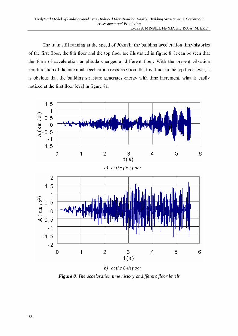
Analytical Model of Underground Train Induced Vibrations on Nearby Building Structures in Cameroon Assessment and Prediction
Lezin S MINSILI He XIA and Robert M EKO
The train still running at the speed of 50kmh the building acceleration time-histories
of the first floor the 8th floor and the top floor are illustrated in figure 8 It can be seen that
the form of acceleration amplitude changes at different floor With the present vibration
amplification of the maximal acceleration response from the first floor to the top floor level it
is obvious that the building structure generates energy with time increment what is easily
noticed at the first floor level in figure 8a
a) at the first floor
b) at the 8-th floor
Figure 8 The acceleration time history at different floor levels
78
Leonardo Electronic Journal of Practices and Technologies
ISSN 1583-1078
Issue 23 July-December 2013
p 63-82
c) at the top level
Figure 8 The acceleration time history at different floor levels
Many investigations support that in a structure under specific modal vibration some of
its parts or elements can be subjected to local resonance and even self-excitation Thus the
observed acceleration amplification from the 3-rd second in figure 8c is related to local
resonance From literature survey [16-17 23-26] it is known that there are no damages on a
building due to train induced ground-borne vibration even if human occupants of the
buildings might be seriously affected But the computed results from the given model shows
that there is the possibility for an underground train passing through an urban area under
specific sub-models described above to excite a particular building or some of its elements
with one of their natural frequencies thus creating the resonance problem Investigations on
this problem are still going on in the Department
Conclusions
The TSS presented in this paper is subdivided into three main sub-models the source
the propagation path and the receiver in order to study and understand the influence of factors
such as dynamic characteristics of the train the railway structure soil and building
characteristics on ground-born vibrations and their effects on nearby building structures
By dividing the TSS model into sub-models it is possible to replace some parts of the
model with data from a particular site if available Thus if a new railway is being designed
79
Analytical Model of Underground Train Induced Vibrations on Nearby Building Structures in Cameroon Assessment and Prediction
Lezin S MINSILI He XIA and Robert M EKO
close to a building a prediction with good accuracy can be made on the effects of the
anticipated railway on the building
With the limitations of available data on TSS interaction in Cameroon experiments
and measurements are still to be done at sites with different geotechnical conditions different
train-track models and different building types to validate obtained results and thus elucidate
these important facts
Acknowledgements
This paper is a continuation of the study presented at the ldquo3rd International Symposium
on Environmental Vibrations Prediction Monitoring Mitigation and Evaluationrdquo 2007
References
1 The World Bank Cameroon Upgrading Low Income Urban Settlements - Country
Assessment Report 2002 AFTU 1 amp 2 Available at
httpwebmiteduurbanupgradingupgradingcase-examplesoverview-africacountry-
assessmentsdownloadCAMEROONpdf (accessed 08062013)
2 NRMP The National Railway Network Master Plan in Cameroon Final report of the
prefeasibility study conducted by KORPEC (KORea Port Engineering Corporation) and
Validated by the Government of Cameroon 2012 p 390-402
3 Du XT Xu Y L Xia H Dynamic interaction of bridgendashtrain system under non-
uniform seismic ground motion Earthquake Engineering Structural Dynamics 2012
41 p 139-157 DOI 101002eqe1122
4 Rodriacuteguez-Tembleque L Abascal R A 3D FEMndashBEM Rolling Contact Formulation
for Unstructured Meshes International Journal of Solids and Structures 2010 47 p
330-353 Available at
httpwwwsciencedirectcomsciencearticlepiiS0020768309003953 (accessed
08062013)
5 Zolghadr Jahromi H Izzuddin BA Zdravkovic L Partitioned analysis of nonlinear
80
Leonardo Electronic Journal of Practices and Technologies
ISSN 1583-1078
Issue 23 July-December 2013
p 63-82
soil-structure interaction using iterative coupling Interaction and Multiscale
Mechanics 2007 1(1) p 33-51
6 Xia H Dynamic Interaction of Vehicles and Structures Science Press Beijing China
2002
7 Chore HS Ingle RK Sawant VA Building frame - pile foundation - soil interaction
analysis a parametric study Interaction and Multiscale Mechanics 2010 3(1) p 55-
79
8 Krylov VV Effects of track properties on ground vibrations generated by high-speed
trains ACUSTICA-Acta Acustica 1998 84(1) p 78-90
9 Daumueller AN Jauregui DV Strain-Based Evaluation of a Steel Through-Girder
Railroad Bridge Hindawi Publishing Corporation Advances in Civil Engineering
2012 Available at httpwwwhindawicomjournalsamseai(accessed 17062013)
10 Xiaoyan L Numerical Analysis of Track Structures in Railway Beijing China Railway
Press 1998
11 Grassie SL Gregory RW Dynamic response of railway track to high frequency
vertical excitation Journal of Mechanical Engineering Science 1982 24(2) p 77-90
12 Flyacuteba L Vibration of Solids and Structures Under Moving Loads London Thomas
Telford 1999
13 Weitsman Y On foundations that react in compression only Journal of Applied
Mechanics 1970 12 p 1019-1030
14 Wang K Liu P Lateral Stability Analysis of Heavy-Haul Vehicle on Curved Track
Based on WheelRail Coupled Dynamics Journal of Transportation Technologies 2012
2(2) p 150-157 Available at httpwwwSciRPorgjournaljtts (accessed 08062013)
15 Woods RD Screening of Surface Waves in Soils Journal of Soil Mechanics and
Foundation Division Proceedings of the ASCE 1968
16 Woods RD Larry PJ Energy-Attenuation Relationships from Construction
Vibrations Vibration Problems in Geotechnical Engineering ASCE Proceedings
Detroit Michigan 1985
17 Eisenman J Deischl F Structure-Borne Sound from Underground Railway Systems
81
Analytical Model of Underground Train Induced Vibrations on Nearby Building Structures in Cameroon Assessment and Prediction
Lezin S MINSILI He XIA and Robert M EKO
82
Der Eisenbahningenieur 1986 3 p 101-110
18 Alshawi M Underwood J Improving the constructability of design solutions through
an integrated system Journal of Engineering Construction and Architectural
Management 1993 3(1amp2) p 47ndash67 doi101108eb021022
19 Patrick C Low Vibration and Noise Track Systems with Tunable Properties for Modern
LRTStreetcar Track on Surface in Urban Areas TIVCrsquo2001 International Symposium
on Traffic Induced Vibrations amp Controls Beijing China 2001 p 161-176
20 Xia H Cao YM Zhang N Numerical Analysis of Vibration Effects of Metro Trains
on Surrounding Environment Int J of Structural Stability and Dynamics 2007 7 p
45-56
21 Le Kouby A Bourgeois E Rocher-Lacoste F Subgrade Improvement Method for
Existing Railway Lines ndash an Experimental and Numerical Study Electronic Journal of
Geotechnical Engineering 2010 15 p461-494
22 Di Mino G Di Liberto CM Nigrelli J A FEM model of rail track-ground system to
calculate the ground borne vibrations a case of rail track with wooden sleepers and k-
fastenings at Castelvetrano Advanced Characterisation of Pavement and Soil
Engineering Materials Athens Greece 2007 p 1737-1752
23 Chauhan HM Pomal MM Bhuta GN A Comparative Study Of Wind Forces On
High-Rise Buildings as Per Is 875-Iii (1987) and Proposed Draft Code (2011) GRA -
Global Research Analysis 2013 2(5) p 59-60
24 Lei X Zhang B Influence of track stiffness distribution on vehicle and track
interactions in track transition Proceedings of the Institution of Mechanical Engineers
Part F Journal of Rail and Rapid Transit 2010 224592 p 592-604 Available at
httppifsagepubcomcontent2246592 (accessed 28082012)
25 Thorat YV Kadam SS Design and Development of Test Setup for VibrationAnalysis
with Soft Foot Indian Journal of Applied Research 2012 2(3) p 59-62
26 Xiaojing Sun Weining Liu Dawen Xie Yingxuan Jia Vibration impacts on adjacent
sensitive buildings induced by metro trains World Tunnel Congress 2008 -
Underground Facilities for Better Environment and Safety ndash India Agra 2008 p 1382-
1389

Leonardo Electronic Journal of Practices and Technologies
ISSN 1583-1078
Issue 23 July-December 2013
p 63-82
c) at the top level
Figure 8 The acceleration time history at different floor levels
Many investigations support that in a structure under specific modal vibration some of
its parts or elements can be subjected to local resonance and even self-excitation Thus the
observed acceleration amplification from the 3-rd second in figure 8c is related to local
resonance From literature survey [16-17 23-26] it is known that there are no damages on a
building due to train induced ground-borne vibration even if human occupants of the
buildings might be seriously affected But the computed results from the given model shows
that there is the possibility for an underground train passing through an urban area under
specific sub-models described above to excite a particular building or some of its elements
with one of their natural frequencies thus creating the resonance problem Investigations on
this problem are still going on in the Department
Conclusions
The TSS presented in this paper is subdivided into three main sub-models the source
the propagation path and the receiver in order to study and understand the influence of factors
such as dynamic characteristics of the train the railway structure soil and building
characteristics on ground-born vibrations and their effects on nearby building structures
By dividing the TSS model into sub-models it is possible to replace some parts of the
model with data from a particular site if available Thus if a new railway is being designed
79
Analytical Model of Underground Train Induced Vibrations on Nearby Building Structures in Cameroon Assessment and Prediction
Lezin S MINSILI He XIA and Robert M EKO
close to a building a prediction with good accuracy can be made on the effects of the
anticipated railway on the building
With the limitations of available data on TSS interaction in Cameroon experiments
and measurements are still to be done at sites with different geotechnical conditions different
train-track models and different building types to validate obtained results and thus elucidate
these important facts
Acknowledgements
This paper is a continuation of the study presented at the ldquo3rd International Symposium
on Environmental Vibrations Prediction Monitoring Mitigation and Evaluationrdquo 2007
References
1 The World Bank Cameroon Upgrading Low Income Urban Settlements - Country
Assessment Report 2002 AFTU 1 amp 2 Available at
httpwebmiteduurbanupgradingupgradingcase-examplesoverview-africacountry-
assessmentsdownloadCAMEROONpdf (accessed 08062013)
2 NRMP The National Railway Network Master Plan in Cameroon Final report of the
prefeasibility study conducted by KORPEC (KORea Port Engineering Corporation) and
Validated by the Government of Cameroon 2012 p 390-402
3 Du XT Xu Y L Xia H Dynamic interaction of bridgendashtrain system under non-
uniform seismic ground motion Earthquake Engineering Structural Dynamics 2012
41 p 139-157 DOI 101002eqe1122
4 Rodriacuteguez-Tembleque L Abascal R A 3D FEMndashBEM Rolling Contact Formulation
for Unstructured Meshes International Journal of Solids and Structures 2010 47 p
330-353 Available at
httpwwwsciencedirectcomsciencearticlepiiS0020768309003953 (accessed
08062013)
5 Zolghadr Jahromi H Izzuddin BA Zdravkovic L Partitioned analysis of nonlinear
80
Leonardo Electronic Journal of Practices and Technologies
ISSN 1583-1078
Issue 23 July-December 2013
p 63-82
soil-structure interaction using iterative coupling Interaction and Multiscale
Mechanics 2007 1(1) p 33-51
6 Xia H Dynamic Interaction of Vehicles and Structures Science Press Beijing China
2002
7 Chore HS Ingle RK Sawant VA Building frame - pile foundation - soil interaction
analysis a parametric study Interaction and Multiscale Mechanics 2010 3(1) p 55-
79
8 Krylov VV Effects of track properties on ground vibrations generated by high-speed
trains ACUSTICA-Acta Acustica 1998 84(1) p 78-90
9 Daumueller AN Jauregui DV Strain-Based Evaluation of a Steel Through-Girder
Railroad Bridge Hindawi Publishing Corporation Advances in Civil Engineering
2012 Available at httpwwwhindawicomjournalsamseai(accessed 17062013)
10 Xiaoyan L Numerical Analysis of Track Structures in Railway Beijing China Railway
Press 1998
11 Grassie SL Gregory RW Dynamic response of railway track to high frequency
vertical excitation Journal of Mechanical Engineering Science 1982 24(2) p 77-90
12 Flyacuteba L Vibration of Solids and Structures Under Moving Loads London Thomas
Telford 1999
13 Weitsman Y On foundations that react in compression only Journal of Applied
Mechanics 1970 12 p 1019-1030
14 Wang K Liu P Lateral Stability Analysis of Heavy-Haul Vehicle on Curved Track
Based on WheelRail Coupled Dynamics Journal of Transportation Technologies 2012
2(2) p 150-157 Available at httpwwwSciRPorgjournaljtts (accessed 08062013)
15 Woods RD Screening of Surface Waves in Soils Journal of Soil Mechanics and
Foundation Division Proceedings of the ASCE 1968
16 Woods RD Larry PJ Energy-Attenuation Relationships from Construction
Vibrations Vibration Problems in Geotechnical Engineering ASCE Proceedings
Detroit Michigan 1985
17 Eisenman J Deischl F Structure-Borne Sound from Underground Railway Systems
81
Analytical Model of Underground Train Induced Vibrations on Nearby Building Structures in Cameroon Assessment and Prediction
Lezin S MINSILI He XIA and Robert M EKO
82
Der Eisenbahningenieur 1986 3 p 101-110
18 Alshawi M Underwood J Improving the constructability of design solutions through
an integrated system Journal of Engineering Construction and Architectural
Management 1993 3(1amp2) p 47ndash67 doi101108eb021022
19 Patrick C Low Vibration and Noise Track Systems with Tunable Properties for Modern
LRTStreetcar Track on Surface in Urban Areas TIVCrsquo2001 International Symposium
on Traffic Induced Vibrations amp Controls Beijing China 2001 p 161-176
20 Xia H Cao YM Zhang N Numerical Analysis of Vibration Effects of Metro Trains
on Surrounding Environment Int J of Structural Stability and Dynamics 2007 7 p
45-56
21 Le Kouby A Bourgeois E Rocher-Lacoste F Subgrade Improvement Method for
Existing Railway Lines ndash an Experimental and Numerical Study Electronic Journal of
Geotechnical Engineering 2010 15 p461-494
22 Di Mino G Di Liberto CM Nigrelli J A FEM model of rail track-ground system to
calculate the ground borne vibrations a case of rail track with wooden sleepers and k-
fastenings at Castelvetrano Advanced Characterisation of Pavement and Soil
Engineering Materials Athens Greece 2007 p 1737-1752
23 Chauhan HM Pomal MM Bhuta GN A Comparative Study Of Wind Forces On
High-Rise Buildings as Per Is 875-Iii (1987) and Proposed Draft Code (2011) GRA -
Global Research Analysis 2013 2(5) p 59-60
24 Lei X Zhang B Influence of track stiffness distribution on vehicle and track
interactions in track transition Proceedings of the Institution of Mechanical Engineers
Part F Journal of Rail and Rapid Transit 2010 224592 p 592-604 Available at
httppifsagepubcomcontent2246592 (accessed 28082012)
25 Thorat YV Kadam SS Design and Development of Test Setup for VibrationAnalysis
with Soft Foot Indian Journal of Applied Research 2012 2(3) p 59-62
26 Xiaojing Sun Weining Liu Dawen Xie Yingxuan Jia Vibration impacts on adjacent
sensitive buildings induced by metro trains World Tunnel Congress 2008 -
Underground Facilities for Better Environment and Safety ndash India Agra 2008 p 1382-
1389

Analytical Model of Underground Train Induced Vibrations on Nearby Building Structures in Cameroon Assessment and Prediction
Lezin S MINSILI He XIA and Robert M EKO
close to a building a prediction with good accuracy can be made on the effects of the
anticipated railway on the building
With the limitations of available data on TSS interaction in Cameroon experiments
and measurements are still to be done at sites with different geotechnical conditions different
train-track models and different building types to validate obtained results and thus elucidate
these important facts
Acknowledgements
This paper is a continuation of the study presented at the ldquo3rd International Symposium
on Environmental Vibrations Prediction Monitoring Mitigation and Evaluationrdquo 2007
References
1 The World Bank Cameroon Upgrading Low Income Urban Settlements - Country
Assessment Report 2002 AFTU 1 amp 2 Available at
httpwebmiteduurbanupgradingupgradingcase-examplesoverview-africacountry-
assessmentsdownloadCAMEROONpdf (accessed 08062013)
2 NRMP The National Railway Network Master Plan in Cameroon Final report of the
prefeasibility study conducted by KORPEC (KORea Port Engineering Corporation) and
Validated by the Government of Cameroon 2012 p 390-402
3 Du XT Xu Y L Xia H Dynamic interaction of bridgendashtrain system under non-
uniform seismic ground motion Earthquake Engineering Structural Dynamics 2012
41 p 139-157 DOI 101002eqe1122
4 Rodriacuteguez-Tembleque L Abascal R A 3D FEMndashBEM Rolling Contact Formulation
for Unstructured Meshes International Journal of Solids and Structures 2010 47 p
330-353 Available at
httpwwwsciencedirectcomsciencearticlepiiS0020768309003953 (accessed
08062013)
5 Zolghadr Jahromi H Izzuddin BA Zdravkovic L Partitioned analysis of nonlinear
80
Leonardo Electronic Journal of Practices and Technologies
ISSN 1583-1078
Issue 23 July-December 2013
p 63-82
soil-structure interaction using iterative coupling Interaction and Multiscale
Mechanics 2007 1(1) p 33-51
6 Xia H Dynamic Interaction of Vehicles and Structures Science Press Beijing China
2002
7 Chore HS Ingle RK Sawant VA Building frame - pile foundation - soil interaction
analysis a parametric study Interaction and Multiscale Mechanics 2010 3(1) p 55-
79
8 Krylov VV Effects of track properties on ground vibrations generated by high-speed
trains ACUSTICA-Acta Acustica 1998 84(1) p 78-90
9 Daumueller AN Jauregui DV Strain-Based Evaluation of a Steel Through-Girder
Railroad Bridge Hindawi Publishing Corporation Advances in Civil Engineering
2012 Available at httpwwwhindawicomjournalsamseai(accessed 17062013)
10 Xiaoyan L Numerical Analysis of Track Structures in Railway Beijing China Railway
Press 1998
11 Grassie SL Gregory RW Dynamic response of railway track to high frequency
vertical excitation Journal of Mechanical Engineering Science 1982 24(2) p 77-90
12 Flyacuteba L Vibration of Solids and Structures Under Moving Loads London Thomas
Telford 1999
13 Weitsman Y On foundations that react in compression only Journal of Applied
Mechanics 1970 12 p 1019-1030
14 Wang K Liu P Lateral Stability Analysis of Heavy-Haul Vehicle on Curved Track
Based on WheelRail Coupled Dynamics Journal of Transportation Technologies 2012
2(2) p 150-157 Available at httpwwwSciRPorgjournaljtts (accessed 08062013)
15 Woods RD Screening of Surface Waves in Soils Journal of Soil Mechanics and
Foundation Division Proceedings of the ASCE 1968
16 Woods RD Larry PJ Energy-Attenuation Relationships from Construction
Vibrations Vibration Problems in Geotechnical Engineering ASCE Proceedings
Detroit Michigan 1985
17 Eisenman J Deischl F Structure-Borne Sound from Underground Railway Systems
81
Analytical Model of Underground Train Induced Vibrations on Nearby Building Structures in Cameroon Assessment and Prediction
Lezin S MINSILI He XIA and Robert M EKO
82
Der Eisenbahningenieur 1986 3 p 101-110
18 Alshawi M Underwood J Improving the constructability of design solutions through
an integrated system Journal of Engineering Construction and Architectural
Management 1993 3(1amp2) p 47ndash67 doi101108eb021022
19 Patrick C Low Vibration and Noise Track Systems with Tunable Properties for Modern
LRTStreetcar Track on Surface in Urban Areas TIVCrsquo2001 International Symposium
on Traffic Induced Vibrations amp Controls Beijing China 2001 p 161-176
20 Xia H Cao YM Zhang N Numerical Analysis of Vibration Effects of Metro Trains
on Surrounding Environment Int J of Structural Stability and Dynamics 2007 7 p
45-56
21 Le Kouby A Bourgeois E Rocher-Lacoste F Subgrade Improvement Method for
Existing Railway Lines ndash an Experimental and Numerical Study Electronic Journal of
Geotechnical Engineering 2010 15 p461-494
22 Di Mino G Di Liberto CM Nigrelli J A FEM model of rail track-ground system to
calculate the ground borne vibrations a case of rail track with wooden sleepers and k-
fastenings at Castelvetrano Advanced Characterisation of Pavement and Soil
Engineering Materials Athens Greece 2007 p 1737-1752
23 Chauhan HM Pomal MM Bhuta GN A Comparative Study Of Wind Forces On
High-Rise Buildings as Per Is 875-Iii (1987) and Proposed Draft Code (2011) GRA -
Global Research Analysis 2013 2(5) p 59-60
24 Lei X Zhang B Influence of track stiffness distribution on vehicle and track
interactions in track transition Proceedings of the Institution of Mechanical Engineers
Part F Journal of Rail and Rapid Transit 2010 224592 p 592-604 Available at
httppifsagepubcomcontent2246592 (accessed 28082012)
25 Thorat YV Kadam SS Design and Development of Test Setup for VibrationAnalysis
with Soft Foot Indian Journal of Applied Research 2012 2(3) p 59-62
26 Xiaojing Sun Weining Liu Dawen Xie Yingxuan Jia Vibration impacts on adjacent
sensitive buildings induced by metro trains World Tunnel Congress 2008 -
Underground Facilities for Better Environment and Safety ndash India Agra 2008 p 1382-
1389