Embed Size (px)
Citation preview

ANALYSIS ON THE PERFORMANCES OF A MICRO GAS TURBINE CO-
GENERATION SYSTEM IN SEWAGE TREATMENT PLANTS
MUHAMMAD ZAID BIN NOR AZLAN
A report submitted in partial fulfillment of
The requirements for the award of the degree of
Bachelor of Mechanical Engineering
Faculty of Mechanical Engineering
UNIVERSITI MALAYSIA PAHANG
JUNE 2013

vii
ABSTRACT
The main role of this study is to analyse the economics performances of micro
gas turbine co-generation systems (MGT-CGSs) in order to define the most interesting
solutions from economic point of view. The study consist two type of economic
analysis, simple and advanced economic analysis. The simple economic analysis is
analysis based on the present and previous data collected that no estimation needed. The
advanced economic analysis is the analysis that need to consider the estimation for the
future value or parameter. The advanced economic analysis give better over view of the
economic analysis of the system. Considering operation of the MGT-CGS under various
loads and efficiency of the MGT-CGSs under partial road condition, the optimal
combination of MGT-CGS (MGT-combination) with different sizes, 30 kW, 65 kW and
200 kW. Economic performance of MGT-CGSs under three typical ambient
temperature conditions and three different scale sewage treatment plant was also
investigated. It was found that MGT combination has the highest total capital cost for
every scale and every temperature condition. Futhermore MGT combination has the
highest total electricity sold. Excluding MGT combination total electricity sold higher
when the MGT power output higher.

viii
ABSTRAK
Peranan utama kajian ini adalah untuk menganalisis ekonomi persembahan
sistem penjanaan turbin gas mikro (MGT-CGSS) untuk menentukan penyelesaian yang
paling menarik dari sudut ekonomi. Kajian ini meliputi dua jenis analisis ekonomi,
analisis ekonomi mudah dan maju. Analisis ekonomi yang mudah adalah analisis
berdasarkan data semasa dan sebelumnya dipungut bahawa tiada anggaran yang
diperlukan. Analisis ekonomi maju adalah analisis yang perlu untuk
mempertimbangkan anggaran untuk nilai masa depan atau parameter. Analisis ekonomi
maju memberi lebih baik ke atas memandangkan analisis ekonomi sistem.
Memandangkan operasi MGT-PS di bawah pelbagai beban dan kecekapan MGT-CGSS
di bawah keadaan jalan separa, gabungan optimum MGT-PS (MGT-gabungan) dengan
saiz yang berbeza, 30 kW, 65 kW dan 200 kW. Prestasi ekonomi MGT-CGSS di bawah
tiga keadaan suhu biasa persekitaran dan tiga skala loji rawatan kumbahan yang berbeza
juga disiasat. Ia telah mendapati bahawa gabungan MGT mempunyai kos modal
tertinggi jumlah bagi setiap skala dan setiap keadaan suhu. Gabungan MGT Tambahan
pula mempunyai jumlah tenaga elektrik tertinggi dijual. Tidak termasuk MGT gabungan
jumlah tenaga elektrik yang dijual lebih tinggi apabila kuasa keluaran MGT yang lebih
tinggi.
.
ix
TABLE OF CONTENTS
TITLE PAGE I
EXAMINER DECLARATION II
SUPERVISOR DECLARATION III
STUDENT DECLARATION IV
ACKNOWLEDGEMENT VI
ABSTRACT VII
TABLE OF CONTENTS IX
LIST OF TABLE XIII
LIST OF FIGURES XIV
LIST OF ABBREVIATIONS XVI
LIST OF SYMBOLS XVII
LIST OF APPENDICES XVIII
CHAPTER 1 INTRODUCTION
1.0 INTRODUCTION 1
1.1 PROJECT BACKGROUND 3
1.2 PROBLEM STATEMENT 3
1.3 OBJECTIVES 4
1.4 SCOPE OF STUDY 4
CHAPTER 2 LITERATURE REVIEW
2.0 INTRODUCTION 5
2.1 WASTEWATER TREATMENT BIOGAS 5
2.2 CO-GENERATION SYSYTEM 7
2.3 TYPES OF CO-GENERATION WITH APPLICATIONS 9

x
2.4 MICRO GAS TURBINE 11
2.5 MICRO GAS TURBINE OPERATION SYSTEM. 13
2.6 MICRO GAS TURBINE PART AND IT’S FUNCTION 14
2.6.1 Compressor and Turbine Wheels 15
2.6.2 Combuster 15
2.6.3 Recuperator 16
2.6.4 Bearings 16
2.6.5 High-Speed Generator 17
2.6.6 Power Electronics Package 17
2.6.7 Balance of Plant 17
2.7 COMPONENT COST 17
2.8 COMMERCIAL MICRO GAS TURBINE 17
CHAPTER 3 METHODOLOGY
3.0 INTRODUCTION 20
3.1 METHODOLOGY FLOW CHART 20
3.2 COLLECT INFORMATION 22
3.2.1 Micro gas turbines co-generation system and its
cost 22
3.2.2 Temperature condition 23
3.2.3 Sewage Treatment Plant 24
3.2.4 Operation conditions 25
3.2.4.1 Full load 25
3.2.4.2 Partial Load 26
3.2.5 Power generated 27

xi
3.3 ECONOMICS PERFORMACES ANALYSIS 29
3.3.1 Simple economic performances analysis of MGT-
CGS 29
3.3.1.1 Capital cost calculation 29
3.3.1.2 Operation & maintenance cost
calculation 29
3.3.1.3 Electricity sold calculation 30
3.3.1.4 Payback period calculation 30
3.3.2 Advanced economics performances analysis of
MGT-CGS 30
3.3.2.1 NPV of electricity sold calculation 31
3.3.2.2 NPV of operation and maintenance cost
calculation 32
3.3.2.3 NPV of profit calculation 32
3.4 CHAPTER SUMMARY 32
CHAPTER 4 RESULT AND DISCUSSION
4.1 INTRODUCTION 33
4.2 ECONOMIC PERFORMANCE 33
4.3 CAPITAL COST OF MGT-CGSS IN ALL SCALES
AND UNDER ALL AMBIENT TEMPERATURE
CONDITIONS
34
4.3.1 Low temperature condition 34
4.3.3 Medium temperature condition 35
4.3.3 High temperature condition 36
4.4 TOTAL ELECTRICITY SOLD OF MGT-CGSs IN ALL
SCALE AND UNDER ALL AMBIENT
TEMPERATURE CONDITIONS
37
4.4.1 Low temperature condition 37
4.4.2 Medium temperature condition 38
4.4.3 High temperature condition 40

xii
4.5 TOTAL OPERATION AND MAINTENANCE COST
(O&M) OF MGT-CGSs IN ALL SCALE AND UNDER
ALL AMBIENT TEMPERATURE CONDITIONS.
42
4.5.1 Low temperature condition 42
4.5.2 Medium temperature condition 43
4.5.3 High temperature condition 45
4.6 PAYBACK PERIOD OF MGT-CGSs IN ALL SCALES
AND UNDER ALL AMBIENT TEMPERATURE
CONDITIONS
47
4.6.1 Low temperature condition 47
4.6.2 Medium temperature condition 48
4.6.3 High temperature condition 49
4.7 NPV OF PROFIT OF MGT-CGSs IN ALL SCALES
AND UNDER ALLAMBIENT TEMPERATURE
CONDITIONS
51
4.7.1 Low temperature condition 51
4.7.2 Medium temperature condition 51
4.7.3 High temperature condition 52
CHAPTER 5 CONCLUSSION
5.1 CONCLUSION 54
5.2 RECOMMENDATION 55
REFERENCES 56
APPENDICES A-D 58

xiii
LIST OF TABLE
Table No Title Page
Table 2.1 Micro gas turbine specification based on capstone and
Ingersoll rand power
18
Table 3.1 MGT cost for the analysis
23
Table 3.2 Temperature range conditions for the analysis process
24
Table 3.3 Sewage Treatment plant parameters for analysis process
24
Table 3.4 Total number of MGT used in full load
25
Table 3.5 Total power generated of MGT-CGSs in all scales under
low ambient temperature condition
27
Table 3.6 Total power generated of MGT-CGSs in all scales under
medium ambient temperature condition
28
Table 3.7 Total power generated of MGT-CGSs in all scales under
high ambient temperature condition
28
xiv
LIST OF FIGURES
Figure No Title Page
Figure 2.1 Biogas production from sewage treatment plants 6
Figure 2.2 Co-generation versus conventional generation 8
Figure 2.3 Industrial Co-generation 10
Figure 2.4 Layout of micro gas turbine based CHP unit
(Bowman Power web site)
12
Figure 2.5 Schematic diagram of micro gas turbine 13
Figure 2.6 Capstone Micro Gas Turbine 19
Figure 3.1 Methodology flow chart 21
Figure 3.2 Micro Gas Turbine Co-generation System 22
Figure 3.3 Electrical power efficiency and MGTs operation at
partial load under low temperature condition
26
Figure 3.4 Electrical power efficiency and MGTs operation at
partial load under medium temperature condition
26
Figure 3.5 Electrical power efficiency and MGTs operation at
partial load under high temperature condition.
27
Figure 4.1 Result of total cost of MGT-CGSs under low temperature
condition.
34
Figure 4.2 Result of total cost of MGT-CGSs under medium
temperature condition.
35
Figure 4.3 Result of total cost of MGT-CGSs under high
temperature condition
36
Figure 4.4 Result of total electricity sold of MGT-CGSs under low
temperature condition
38
Figure 4.5 Result of total electricity sold of MGT-CGSs under
medium temperature condition
39
Figure 4.6 Result of total electricity sold of MGT-CGSs under high
temperature condition.
41

xv
Figure 4.7 Result of total O&M cost of MGT-CGSs under low
temperature condition
43
Figure 4.8 Result of total O&M cost of MGT-CGSs under medium
temperature Condition
44
Figure 4.9 Result of total O&M cost of MGT-CGSs under high
temperature condition
46
Figure 4.10 Result of payback period of MGT-CGSs under low
temperature condition
47
Figure 4.11 Result of payback period of MGT-CGSs under medium
temperature condition
48
Figure 4.12 Result of payback period of MGT-CGSs under high
temperature condition
50
Figure 4.13 NPV of profit of MGT-CGSs under low temperature
condition
51
Figure 4.14 NPV of profit of MGT-CGSs under medium temperature
condition
52
Figure 4.15 NPV of profit of MGT-CGSs under high temperature
condition
53

xvi
LIST OF ABBREVIATIONS
MGT Micro Gas Turbine
MGT-CGSs Micro Gas Turbine Co-Generation System
O&M Operation And Maintenance
NPV Net present value
CHP Combined heat and power
IGCC Coal-gasification Combined-cycle
PFBC Pressurized Fluidizied Bed Combustion
EHE Exhaust Heat Exchanger
LCC Life Cycle Costing

xvii
LIST OF SYMBOLS
Capital cost
Operation and maintenance Cost
Total power generated
Total electric power capacity
Total electricity sold

xviii
LIST OF APPENDICES
A NPV for electricity sold
58
B NPV for Operation & Maintenance 59
C NPV for Profit 60
D NPV for Payback Period 61
CHAPTER 1
INTRODUCTION
1.0 INTRODUCTION
Interest has recently been shown in the utilization of biomass by a co-generation
system (CGS) and its applications have been increasing. One of the concept system
used of renewable energy if co-generation system that is combination of heat and power
to produce useful energy for using. Co-generation, when associated with the gas turbine,
is a relatively old technology which dates back to pre-World War II years. The concept
of co-generation involves the generation of steam and electricity in one operation. The
waste heat from the exhaust of the turbine is then recovered in the form of steam or hot
water. In the "bottoming cycle" a gas turbine may be used as a combustor only (Y. H.
Kiang, 1981 ). Co-generation, simply, is the generation of energy for one process from
the excess energy supplied to another process (M. Hall, Co-generation. 1981). Co-
generation, then, is nothing more than an economically sound method for the
conservation of resources. Thus, the benefits from the use of co-generation may be cited
as energy conservation, environmental improvement and financial attractiveness to
investors. In the near future energy efficiency must no longer be a choice, but a
commitment.
Biogas production technology such as anaerobic digestion has been available for
many decades, but it has not been widely used because of the availability of cheap fossil
fuel. Understanding and application of anaerobic treatment have made significant gains
in the past 30 years.

2
One of the sources of energy is from biogas and from sewage and its only one
facility that has been continuously producing biogas by anaerobic digestion is a sewage
treatment plant. Anaerobic digestion is an important process for stabilizing and reducing
municipal sewage sludge. Although some of the biogas produced by anaerobic digestion
has been utilized as fuel to cover the heat demand of the plant, the large amount of
remaining biogas has not been fully utilized. For biogas from a sewage treatment,
amount of biogas produced in plants, is small especially in middle- and small-scale
sewage treatment plants. The application of presently usable prime movers with an
output of more than a few hundred kilowatts is difficult because of small scale and
medium will produce only small amount of energy base on it efficiency.
Another recently developed of new and renewable sustainability energy is from
micro-scale fuel cells, fuel cell micro-grid, reciprocating engines and gas turbines are
prime movers that have output power less than this capacity. Fuel cells are one of the
most promising technologies for the next generation of green hydrogen applications.
They are suitable for many kinds of power plants, ranging from small auxiliary power
units to distributed heat and power co-generation systems. Has been tested that fuel
cells are one of the most promising technology, but they still have disadvantages and
problems in lifetime and cost of production and maintaining (Staffell I, Green R,
Kendall K, 2008).
One of largely used of co-generation system is used of micro gas turbine or gas
turbine because gas turbine and micro gas turbine produce large amount of wasted heat
while it combusted. MGTs are gas turbines that operate on the basis of the Brayton
cycle. The biogas-fuelled Micro Gas Turbine Co-generation Gas System (MGTCGS)
was mainly composed of the MGT, and an exhaust heat exchanger (EHE), and the MGT
was a regenerative single shaft MGT. Atmospheric air enters the MGT passing through
a generator, a compressor, a recuperator, a combustion chamber, a turbine and then the
recuperator. MGT-CGSs have variant electrical power outputs some have the electrical
power outputs of 30 kW (MGT30), 65 kW (MGT-65) and 200 kW (MGT-200). The
application of Micro Gas Turbine-Co-generation system (MGT-CGS) is not largely
used in on sewage system on middle- and small-scale sewage treatment plants for small
office and small building.

3
1.1 PROJECT BACKGROUND
The main idea of this project is to expose student with many expect of
engineering economics that exposure to the costing and estimating of this micro gas
turbine-co-generation system project analysis. First and foremost in importance are the
cost analysis, estimation, and management of the system of the micro gas turbine-co-
generation system. The analysis consist of analysis about simple economic
performance and also some advanced economic performances of micro gas turbine-co-
generation system. The task follows a common product development activity, where
student need to apply all their engineering knowledge and skill to complete this project.
In, random student must know some basic knowledge which about the micro gas
turbine-co-generation system, engineering economics analysis and estimation of current
economic situation.
1.2 PROBLEM STATEMENT
There are different type of MGT with different electricity output capacity that
give different power efficiency. The MGT price and cost also different based on it
electricity output capacity. From the market , the MGT price is higher when the power
output is lower. In this situation how to analyse economic performance of the most
suitable MGT used (single or combination) by considering the cost and the efficiency of
the MGT that operate under different ambient temperature in different scale of sewage
treatment plant with various electricity output capacity of MGT. Based on the
information collected the higher the size of electricity output capacity of MGT the
higher the power can be generated. The MGT-CGSs will generate power based on the
power demand needed and heat demand and power demand of the plant is affected by
ambient temperature.When the power demand is high the MGT-CGSs will generated
more power or more than one MGT-CGSs will operate to support the demand. The
suitable size (electricity output capacity) of micro gas turbine co-generation systems
(MGT-CGSs) depending on scale of the sewage treatment plant was. Considering
operation of the MGT-CGS under various loads and efficiency of the MGT-CGS under
a partial load condition, the optimal combination of MGT-CGSs (MGT-Combination)
with different sizes, 30 kW, 65 kW and 200 kW, was also.

4
What is the result of economics performance of MGT-CGS with different power output
when running at different ambient temperature in different scales sewage treatment
plants.
1.3 OBJECTIVES
Objectives of this project are:
• To evaluate the economic performances of micro gas turbine-co-generation
system (MGT-CGS) in sewage treatment plants
• To compare the economic performances of MGT-CGS base on various
electrical power outputs and different ambient temperature condition.
1.4 SCOPES OF STUDY
The Scopes for this particular research are bounded by these four matters and
therefore will be followed throughout the research which are:
• Analysis the operational system of micro gas turbine-co-generation system
in sewage treatment plants.
• Analysis of the calculation about simple economic analysis (initial cost,
operation & maintenance cost)
• Analysis of the calculation about advance economic analysis (life-cycle
method, by using net present value)
• Analyze and compare the economics performance of micro gas turbine-co-
generation system in sewage treatment base on different ambient
temperature and micro gas turbine output power.

CHAPTER 2
LITERATURE REVIEW
2.0 INTRODUCTION
This chapter is discussed on some literature studies related to the co-generation
system principle, micro gas turbine, micro gas turbine-co-generation system and related
system that related to this topic. Apart from that, this chapter is organized in a
systematic order so that the reader can understand this chapter easily. Other relevant
studies that are related to the performance of this system also been discussed.
2.1 WASTEWATER TREATMENT BIOGAS
Wastewater treatment biogas is produced from the anaerobic digestion of
domestic/industrial wastewater sludge. During the wastewater treatment process, solids
from primary and secondary treatment are collected and further processed, via
digestion, to stabilize and reduce the volume of the sludge. The digestion is performed
either aerobically (in the presence of oxygen) or anaerobically (without oxygen) to
produce biogas. Anaerobic digestion and wastewater treatment take place in a closed or
covered tank to exclude air or oxygen from the waste. Anaerobic treatment has been
historically used to biologically stabilize high-strength wastes at a low cost.
In many cases, the biogas has not been used as an energy resource but has been
burned in a flare and discharged to the atmosphere. Biogas is also generated from other
anaerobic wastewater treatment processes, including anaerobic lagoons and facultative
lagoons. (Dr. N. Lymberopoulos, 2004).

6
Wastewater treatment biogas consists of approximately 55 to 65 percent
methane, 30 percent CO2, and other inert gases such as nitrogen. This composition
results in a heating value of approximately 550 to 650 Btu/scf.40
Today, most
wastewater treatment plants that employ anaerobic digestion collect and use their biogas
on site.
Figure 2.1: Biogas production from sewage treatment plants
There are four main types of biogas applications, production of heat and
steam,electricity Generation co-generation, use as vehicle fuel, and possibly production
of chemicals. These applications are governed by national frameworks like the tax
system, subsidies, green energy certificates and increased feed-in tariffs for electricity,
availability of heat or gas grids. Worldwide, biogas is mainly used in combined heat and
power (CHP) applications, whereas various EU countries have embarked on
programmes to achieve a growing share of biogas in the transport sector, especially
attractive in view of the steady increase of the cost of fossil fuels. (I. BODÍK et al,
2010).
7
2.2 CO-GENERATION SYSYTEM
Co-generation is not a new concept, Co-generation when associated with the gas
turbine, is a relatively old technology which dates back to pre-World War II years. The
concept of co-generation involves the generation of steam and electricity in one
operation. The "topping cycle" generates electricity when the turbine is directly coupled
to a generator. The waste heat from the exhaust of the turbine is then recovered in the
form of steam or hot water. In the "bottoming cycle" a gas turbine may be used as a
combustor only. Industrial plants led to the concept of co-generation back in the1880s
when steam was the primary source of energy in industry, and electricity was just
surfacing as a product for both power and lighting (Orlando JA,1996).The use of co-
generation became common practice as engineers replaced steam driven belt and pulley
mechanisms with electric power and motors, moving from mechanical powered systems
to electrically powered systems. During the early parts of the 20th century, most
electricity generation was from coal fired boilers and steam turbine generators, with the
exhaust steam used for industrial heating applications.
In the early 1900s, as much as 58% of the total power produced in the USA by
on-site industrial power plants was estimated to be cogenerated (Frangopoulos CA,
2001) .with the exhaust t heat also he exhaust from the turbine may be fed to a steam
generator (HRSG), and the resulting steam may be used as process steam or in a steam
Rankine cycle. A secondary cycle with an organic fluid may be used at the condenser
end to drive a turbine for generating byproduct electricity. During the decade of the
1960s, industrial users recognized the gas turbine as a reliable prime mover for base
load process applications. Accordingly, gas turbine co-generation systems were
installed in various industries. More recently, worldwide concern about the cost and
efficient use of energy is providing continuing opportunities for gas turbine co-
generation systems (Y. S. H. Najjar, 1987). In principle, the simplest modification to be
introduced to the simple gas turbine engine cycle was to recover part of the exhaust
energy in the heat exchanger of a recuperative cycle (Y. S. H. Najjar, 1987). Exhaust
energy can be recovered more efficiently, however, in a hot water or heat recovery
steam generator (HRSG).

8
Such a co-generation system may have a power-to-heat ratio of 4 to 5 times that
of steam turbines, in addition to the greater potential for generating power in excess of
on-site needs (R. H. Williams,1978). The steam may be used in heating, cooling and
many other industrial processes.
There is a growing potential in the use of micro-co-generation systems in the
residential sector because they have the ability to produce both useful thermal energy
and electricity from a single source of fuel such as oil or natural gas with a high
efficiency. In co-generation systems, the efficiency of energy conversion increases to
over 80% as compared to an average of 30–35% in conventional fossil fuel fired
electricity generation systems. Fig. 1 illustrates how the internal energy from the fuel is
converted into useful thermal energy and electrical energy for a conventional fossil fuel
fired electricity generation and a co-generation system (European Commission,
Directorate General for Energy ,1999) .
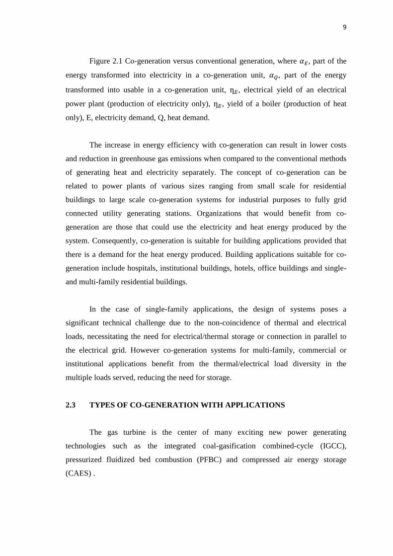
Figure 2.2: Co-generation versus conventional generation
(Source: journal of combined and heat (CHP))
9
Figure 2.1 Co-generation versus conventional generation, where , part of the
energy transformed into electricity in a co-generation unit, , part of the energy
transformed into usable in a co-generation unit, , electrical yield of an electrical
power plant (production of electricity only), , yield of a boiler (production of heat
only), E, electricity demand, Q, heat demand.
The increase in energy efficiency with co-generation can result in lower costs
and reduction in greenhouse gas emissions when compared to the conventional methods
of generating heat and electricity separately. The concept of co-generation can be
related to power plants of various sizes ranging from small scale for residential
buildings to large scale co-generation systems for industrial purposes to fully grid
connected utility generating stations. Organizations that would benefit from co-
generation are those that could use the electricity and heat energy produced by the
system. Consequently, co-generation is suitable for building applications provided that
there is a demand for the heat energy produced. Building applications suitable for co-
generation include hospitals, institutional buildings, hotels, office buildings and single-
and multi-family residential buildings.
In the case of single-family applications, the design of systems poses a
significant technical challenge due to the non-coincidence of thermal and electrical
loads, necessitating the need for electrical/thermal storage or connection in parallel to
the electrical grid. However co-generation systems for multi-family, commercial or
institutional applications benefit from the thermal/electrical load diversity in the
multiple loads served, reducing the need for storage.
2.3 TYPES OF CO-GENERATION WITH APPLICATIONS
The gas turbine is the center of many exciting new power generating
technologies such as the integrated coal-gasification combined-cycle (IGCC),
pressurized fluidized bed combustion (PFBC) and compressed air energy storage
(CAES) .

10
Moreover, gas turbine CHP plants are highly competitive with steam turbines
and internal combustion engines as prime movers, yielding a higher rate of return, better
flexibility, higher efficiency, especially when using aero-derived gas turbines that have
good part-load efficiencies and low downtime, with the aero-derivative type having a
removable gas generator that relates to most of the critical maintenance. Co-generation
with gas turbines encompasses heating air for fired heaters (G. Laquaniello and S.
Guerrini, 1984) ,production of steam for cooling gas turbine blades (K. Takeya and H.
Yasui,1987) using heat rejected from closed-cycle gas turbines (K. Bammert, 1986) ,
producing chilled water or cold air from an absorption system (Y. S. H. Najjar and A.
M. Radhwan,1991) converting heat for space heating by the use of heat pumps (Y. S.
H. Najjar and M. Nahas,1989), using liquefied hydrogen as fuel and coolant producing
air for compressed air storage plants and producing power from an absorption cycle to
drive reverse osmosis desalination .Other co-generation systems include steam power
plants ,diesel power plants ,fuel cells and nuclear power plants .There are many gas
turbine co-generation projects around the world, some producing hot water and steam
for district heating , plus combined-cycle for power, heating and air conditioning and
other applications.
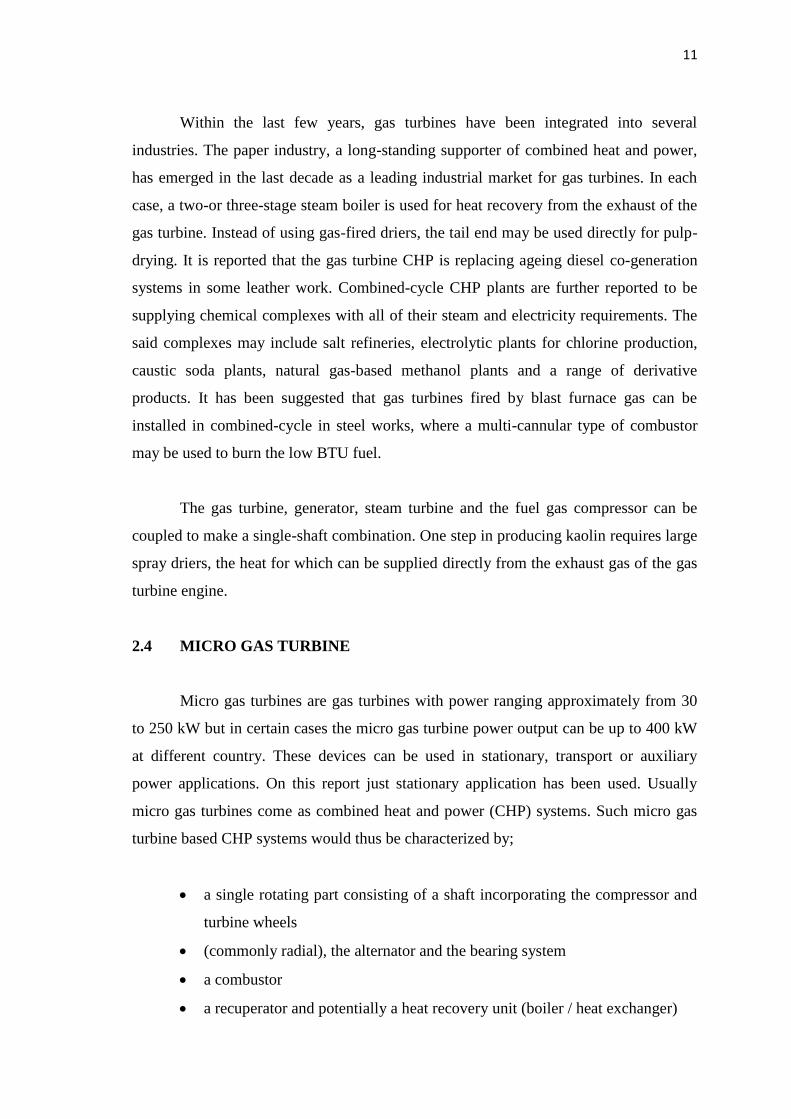
Figure 2.3: Industrial Co-generation
(Source: journal of combined and heat (CHP))
11
Within the last few years, gas turbines have been integrated into several
industries. The paper industry, a long-standing supporter of combined heat and power,
has emerged in the last decade as a leading industrial market for gas turbines. In each
case, a two-or three-stage steam boiler is used for heat recovery from the exhaust of the
gas turbine. Instead of using gas-fired driers, the tail end may be used directly for pulp-
drying. It is reported that the gas turbine CHP is replacing ageing diesel co-generation
systems in some leather work. Combined-cycle CHP plants are further reported to be
supplying chemical complexes with all of their steam and electricity requirements. The
said complexes may include salt refineries, electrolytic plants for chlorine production,
caustic soda plants, natural gas-based methanol plants and a range of derivative
products. It has been suggested that gas turbines fired by blast furnace gas can be
installed in combined-cycle in steel works, where a multi-cannular type of combustor
may be used to burn the low BTU fuel.
The gas turbine, generator, steam turbine and the fuel gas compressor can be
coupled to make a single-shaft combination. One step in producing kaolin requires large
spray driers, the heat for which can be supplied directly from the exhaust gas of the gas
turbine engine.
2.4 MICRO GAS TURBINE
Micro gas turbines are gas turbines with power ranging approximately from 30
to 250 kW but in certain cases the micro gas turbine power output can be up to 400 kW
at different country. These devices can be used in stationary, transport or auxiliary
power applications. On this report just stationary application has been used. Usually
micro gas turbines come as combined heat and power (CHP) systems. Such micro gas
turbine based CHP systems would thus be characterized by;
a single rotating part consisting of a shaft incorporating the compressor and
turbine wheels
(commonly radial), the alternator and the bearing system
a combustor
a recuperator and potentially a heat recovery unit (boiler / heat exchanger)