Embed Size (px)
Citation preview
Analysis of Voided Deck Slab and Cellular Deck
Slab using Midas Civil
Abstract:-The paper deals with analysis of the voided deck slab
and cellular deck slab for medium bridge span ranging from 7.0
m to 15.0 m. The analysis presented illustrates the behavior of
bending moments, Shear Force, displacements, reactions due to
change in Span for various load conditions of voided and
cellular decks. Generally for construction of a medium bridge
idea for selection depends upon various factors. When Solid slab
becomes uneconomical we have to go for the next alternative to
make our deck economical as well as safe. However, Deciding of
deck may become difficult unless we have an idea on its model
and shape. As we know we use voided slab for a void depth upto
60% and cellular deck slab if the void depth is more than
60%.As in any text book it is not clear about the behavior of
using various shapes as voids. In this project an experiment has
been done using Midas civil software by taking void as 60% of
total deck depth and analyzed under various Indian code
loading conditions as per IRC and results has been compared to
know the behavior of the shape constraint for deciding a bridge
deck. A real voided slab model is taken for deciding dimensions
and changed in line with IRCS SP 64-2005. From that model
keeping width of the deck slab as constant (i.e 11.05m) by using
shape of void as circular and rectangular analysis has been
done in Midas civil for various spans ranging from 7.00m to
15.00m for an interval of 0.2m so total (41+41) models analyzed
and their Beam forces, Reactions and Displacements in x,y and z
directions have been compared interms of span wise.
Keywords -Voided Slab deck, Cellular Slab deck, MIDAS-
CIVIL
I. INTRODUCTION
One of the most important factors affecting the design of the
structures is the shape of the structure. The analysis presented
illustrates the behavior of bending moments, Shear Force,
displacements, reactions due to change in Span for various
load conditions and vehicles. Generally for construction of a
medium bridge idea for selection depends upon various
factors. When Solid slab becomes uneconomical we have to
go for the next alternative to make our deck economical as
well as safe. However, Deciding of deck may become
difficult unless we have an idea on its model and shape. As
we know we use voided slab for a void depth upto 60% and
cellular deck slab if the void depth is more than 60%.As in
any text book it is not clear about the behavior of using
various shapes as void. So by using shape of void as circular
and rectangular.
There are several methods available for the analysis of
bridges. In each analysis methods, the three dimensional
bridge structures are usually simplified by means of
assumptions in the Materials, geometry and relationship
between components. The accuracy of the structural analysis
is dependent upon the choice of a particular method and its
assumptions. Available research works on some methods are
grillage analogy method, orthotropic plate theory method,
folded plate method, finite strip method, finite element
method, computer programming and experimental
studies.E.C Hambly et al. applied grillage analogy method to
the multi-cell superstructure. In this I have taken Midas Civil
for analyzing the decks.
II. VOIDED OR CELLULAR DECK SLAB:
A. Need of Voided or cellular Deck Slab
Slab bridges are under-used principally because of lack of
refinement of the preliminary costings carried out by most of
the contractors/Estimators. The unit costs of formwork,
concrete, reinforcement and prestress tendons should be
clearly be lower for a solid slab deck than for more complex
cross sections such as voided slab or multicellular slab decks.
However in early stages of the project when options are being
compared, this is frequently overlooked.
Slabs allow the designer to minimize the depth of
construction and provide a flat soffit where this is
architecturally desirable. Their use is limited principally by
their high self weight. Typical medium-span concrete bridge
decks with twin rib or box cross sections have anequivalent
thickness(cross section area divided by width) that generally
lies between 450mm and 600mm. Thus when the thickness of
slab exceeds about 700 mm, the cost of carrying the self-
weight tends to outweigh its virtues of simplicity.
B. Voids shape and Material:-
Voids may be circular, quasi-circular such as octagonal, or
rectangular. Rectangular voids are assimilated to multicell
boxes.
B.
Vaignan
Department of Civil Engineering
V R Siddhartha Engineering College
Vijayawada, India
Dr.
B.
S.
R.
K Prasad
Department of Civil Engineering
V R Siddhartha Engineering College
Vijayawada, India
International Journal of Engineering Research & Technology (IJERT)
IJERT
IJERT
ISSN: 2278-0181
www.ijert.orgIJERTV3IS090981
(This work is licensed under a Creative Commons Attribution 4.0 International License.)
Vol. 3 Issue 9, September- 2014
1277
C. Methods are used to create voids:-
The commonest is to use expanded polystyrene, which has
advantage that it is light easy to cut. In theory, Polystyrene
voids can be made of any shape, either by building up
rectangular sections, or by sharping standard sections. In
practice, the labour involved in building up or cutting
sections is not economical, and cylindrical voids are usually
used, these cylinders may be cut away locally to widen ribs,
or to accommodate prestress anchors, drainage gullies etc.
D. Development of voided slabs
The development of voided slab is similar to that of solid
slabs. In decks where the maximum stress on the top and
bottom fibers is less than the permissible limit, It is cost
effective to create side cantilevers and to remove material
from the centre of wide slabs, creating effectively a voided
ribbed slab.
In this project the numerous finite element models are
analyzed using Midas civil software by taking void as 60% of
total deck depth and analyzed under various Indian code
loading conditions as per IRC and results has been compared
to know the behavior of the shape constraint for deciding a
bridge deck. A voided slab model is taken for deciding
dimensions as per . From that model keeping width of the
deck slab as constant (i.e 11.05m) analysis on which supports
on two piers of size 625mm and 725mm of 5.5m height has
been taken just for showing supports and analysis has been
done in midas civil for various spans ranging from 7.00m to
15.00m for an interval of 0.2m so total (41+41) models
analyzed and their Beam forces, Reactions and
Displacements in x,y and z directions have been compared
interms of span wise.
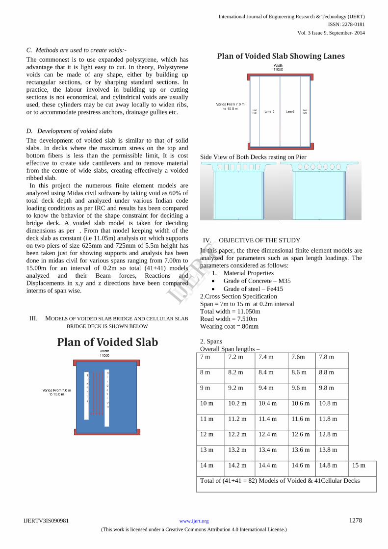
III. MODELS OF VOIDED SLAB BRIDGE AND CELLULAR SLAB
BRIDGE DECK IS SHOWN BELOW
Side View of Both Decks resting on Pier
IV. OBJECTIVE OF THE STUDY
In this paper, the three dimensional finite element models are
analyzed for parameters such as span length loadings. The
parameters considered as follows:
1. Material Properties
Grade of Concrete – M35
Grade of steel – Fe415
2.Cross Section Specification
Span = 7m to 15 m at 0.2m interval
Total width = 11.050m
Road width = 7.510m
Wearing coat = 80mm
2. Spans
Overall Span lengths –
7 m 7.2 m 7.4 m 7.6m 7.8 m
8 m 8.2 m 8.4 m 8.6 m 8.8 m
9 m 9.2 m 9.4 m 9.6 m 9.8 m
10 m 10.2 m 10.4 m 10.6 m 10.8 m
11 m 11.2 m 11.4 m 11.6 m 11.8 m
12 m 12.2 m 12.4 m 12.6 m 12.8 m
13 m 13.2 m 13.4 m 13.6 m 13.8 m
14 m 14.2 m 14.4 m 14.6 m 14.8 m 15 m
Total of (41+41 = 82) Models of Voided & 41Cellular Decks
International Journal of Engineering Research & Technology (IJERT)
IJERT
IJERT
ISSN: 2278-0181
www.ijert.orgIJERTV3IS090981
(This work is licensed under a Creative Commons Attribution 4.0 International License.)
Vol. 3 Issue 9, September- 2014
1278
2. Loadings considered:
a) Self weight of box girder
b) Super-imposed dead load from wearing coat and foot path
c) Live loads as per IRC:6-2010 of following vehicles
Class A Vehicle
Class AA Vehicle
Class B Vehicle
Class 70 R Vehicle
3. Loading considered for lanes
SL.No Lane 1 Lane 2
1. CLASS 70 R CLASS B
2. CLASS A CLASS 70 R
3. CLASS A CLASS AA
4. CLASS B CLASS AA
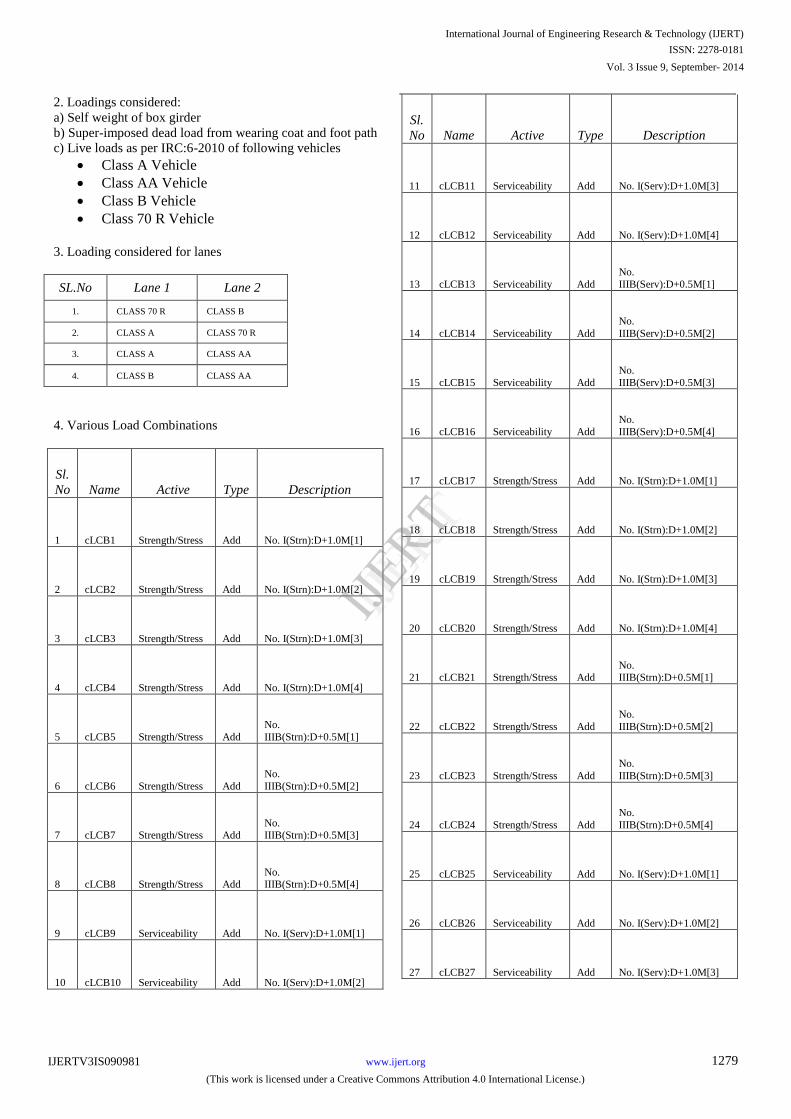
4. Various Load Combinations
Sl.
No Name Active Type Description
1 cLCB1 Strength/Stress Add No. I(Strn):D+1.0M[1]
2 cLCB2 Strength/Stress Add No. I(Strn):D+1.0M[2]
3 cLCB3 Strength/Stress Add No. I(Strn):D+1.0M[3]
4 cLCB4 Strength/Stress Add No. I(Strn):D+1.0M[4]
5 cLCB5 Strength/Stress Add
No.
IIIB(Strn):D+0.5M[1]
6 cLCB6 Strength/Stress Add
No.
IIIB(Strn):D+0.5M[2]
7 cLCB7 Strength/Stress Add No. IIIB(Strn):D+0.5M[3]
8 cLCB8 Strength/Stress Add No. IIIB(Strn):D+0.5M[4]
9 cLCB9 Serviceability Add No. I(Serv):D+1.0M[1]
10 cLCB10 Serviceability Add No. I(Serv):D+1.0M[2]
Sl.
No Name Active Type Description
11 cLCB11 Serviceability Add No. I(Serv):D+1.0M[3]
12 cLCB12 Serviceability Add No. I(Serv):D+1.0M[4]
13 cLCB13 Serviceability Add
No.
IIIB(Serv):D+0.5M[1]
14 cLCB14 Serviceability Add
No.
IIIB(Serv):D+0.5M[2]
15 cLCB15 Serviceability Add
No.
IIIB(Serv):D+0.5M[3]
16 cLCB16 Serviceability Add
No.
IIIB(Serv):D+0.5M[4]
17 cLCB17 Strength/Stress Add No. I(Strn):D+1.0M[1]
18 cLCB18 Strength/Stress Add No. I(Strn):D+1.0M[2]
19 cLCB19 Strength/Stress Add No. I(Strn):D+1.0M[3]
20 cLCB20 Strength/Stress Add No. I(Strn):D+1.0M[4]
21 cLCB21 Strength/Stress Add No. IIIB(Strn):D+0.5M[1]
22 cLCB22 Strength/Stress Add
No.
IIIB(Strn):D+0.5M[2]
23 cLCB23 Strength/Stress Add
No.
IIIB(Strn):D+0.5M[3]
24 cLCB24 Strength/Stress Add
No.
IIIB(Strn):D+0.5M[4]
25 cLCB25 Serviceability Add No. I(Serv):D+1.0M[1]
26 cLCB26 Serviceability Add No. I(Serv):D+1.0M[2]
27 cLCB27 Serviceability Add No. I(Serv):D+1.0M[3]
International Journal of Engineering Research & Technology (IJERT)
IJERT
IJERT
ISSN: 2278-0181
www.ijert.orgIJERTV3IS090981
(This work is licensed under a Creative Commons Attribution 4.0 International License.)
Vol. 3 Issue 9, September- 2014
1279
Sl.
No Name Active Type Description
28 cLCB28 Serviceability Add No. I(Serv):D+1.0M[4]
29 cLCB29 Serviceability Add
No. IIIB(Serv):D+0.5M[1]
30 cLCB30 Serviceability Add
No.
IIIB(Serv):D+0.5M[2]
31 cLCB31 Serviceability Add
No.
IIIB(Serv):D+0.5M[3]
32 cLCB32 Serviceability Add
No.
IIIB(Serv):D+0.5M[4]
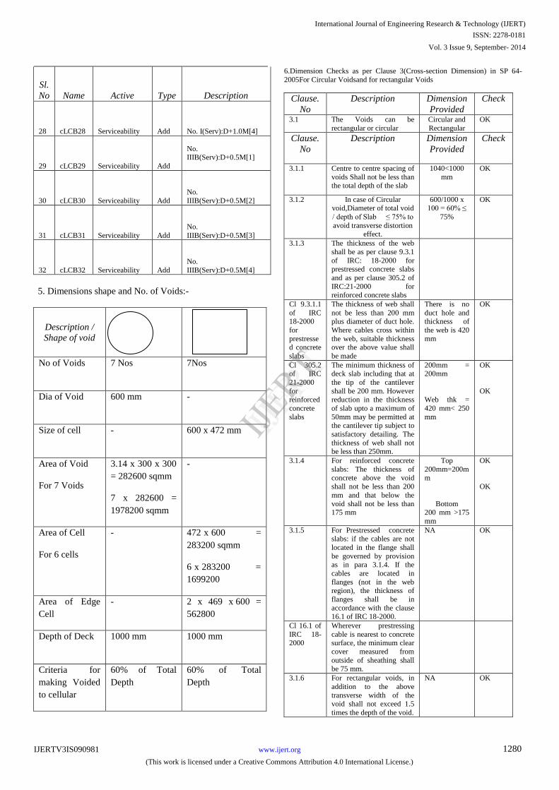
5. Dimensions shape and No. of Voids:-
Description /
Shape of void
No of Voids 7 Nos 7Nos
Dia of Void 600 mm -
Size of cell - 600 x 472 mm
Area of Void
For 7 Voids
3.14 x 300 x 300
= 282600 sqmm
7 x 282600 =
1978200 sqmm
-
Area of Cell
For 6 cells
- 472 x 600 =
283200 sqmm
6 x 283200 =
1699200
Area of Edge
Cell
- 2 x 469 x 600 =
562800
Depth of Deck 1000 mm 1000 mm
Criteria for
making Voided
to cellular
60% of Total
Depth
60% of Total
Depth
6.Dimension Checks as per Clause 3(Cross-section Dimension) in SP 64-
2005For Circular Voids and for rectangular Voids
Clause.
No
Description Dimension
Provided
Check
3.1 The Voids can be
rectangular or circular
Circular and
Rectangular
OK
Clause.
No
Description Dimension
Provided
Check
3.1.1 Centre to centre spacing of
voids Shall not be less than the total depth of the slab
1040<1000
mm
OK
3.1.2 In case of Circular void,Diameter of total void
/ depth of Slab ≤ 75% to
avoid transverse distortion
effect.
600/1000 x 100 = 60% ≤
75%
OK
3.1.3 The thickness of the web
shall be as per clause 9.3.1
of IRC: 18-2000 for prestressed concrete slabs
and as per clause 305.2 of
IRC:21-2000 for reinforced concrete slabs
Cl 9.3.1.1
of IRC 18-2000
for
prestressed concrete
slabs
The thickness of web shall
not be less than 200 mm plus diameter of duct hole.
Where cables cross within
the web, suitable thickness over the above value shall
be made
There is no
duct hole and thickness of
the web is 420
mm
OK
Cl 305.2 of IRC
21-2000
for reinforced
concrete
slabs
The minimum thickness of deck slab including that at
the tip of the cantilever
shall be 200 mm. However reduction in the thickness
of slab upto a maximum of
50mm may be permitted at the cantilever tip subject to
satisfactory detailing. The
thickness of web shall not be less than 250mm.
200mm = 200mm
Web thk =
420 mm< 250
mm
OK
OK
3.1.4 For reinforced concrete
slabs: The thickness of
concrete above the void shall not be less than 200
mm and that below the
void shall not be less than 175 mm
Top
200mm=200m
m
Bottom 200 mm >175
mm
OK
OK
3.1.5 For Prestressed concrete slabs: if the cables are not
located in the flange shall
be governed by provision as in para 3.1.4. If the
cables are located in
flanges (not in the web region), the thickness of
flanges shall be in
accordance with the clause 16.1 of IRC 18-2000.
NA OK
Cl 16.1 of
IRC 18-2000
Wherever prestressing
cable is nearest to concrete surface, the minimum clear
cover measured from
outside of sheathing shall be 75 mm.
3.1.6 For rectangular voids, in
addition to the above
transverse width of the
void shall not exceed 1.5
times the depth of the void.
NA OK
International Journal of Engineering Research & Technology (IJERT)
IJERT
IJERT
ISSN: 2278-0181
www.ijert.orgIJERTV3IS090981
(This work is licensed under a Creative Commons Attribution 4.0 International License.)
Vol. 3 Issue 9, September- 2014
1280
3.2 The portion of the slab
near the supports in the longitudinal direction on
each side shall be made
solid for a minimum length equivalent to the depth of
slab or 5% of the effective
span whichever is greater.
5%of7000=35
0mm < 1555mm
5% of 5000 =750mm<155
5mm
OK
OK
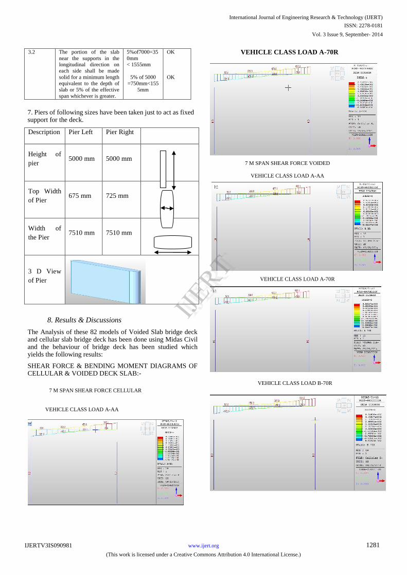
7. Piers of following sizes have been taken just to act as fixed support for the deck.
Description Pier Left Pier Right
Height of
pier 5000 mm 5000 mm
Top Width
of Pier 675 mm 725 mm
Width of
the Pier 7510 mm 7510 mm
3 D View
of Pier
8. Results & Discussions
The Analysis of these 82 models of Voided Slab bridge deck and cellular slab bridge deck has been done using Midas Civil and the behaviour of bridge deck has been studied which yields the following results:
SHEAR FORCE & BENDING MOMENT DIAGRAMS OF CELLULAR & VOIDED DECK SLAB:-
VEHICLE CLASS LOAD B-70R
7 M SPAN SHEAR FORCE CELLULAR
VEHICLE CLASS LOAD A-AA
7 M SPAN SHEAR FORCE VOIDED
VEHICLE CLASS LOAD A-AA
VEHICLE CLASS
LOAD A-70R
VEHICLE CLASS LOAD A-70R
International Journal of Engineering Research & Technology (IJERT)
IJERT
IJERT
ISSN: 2278-0181
www.ijert.orgIJERTV3IS090981
(This work is licensed under a Creative Commons Attribution 4.0 International License.)
Vol. 3 Issue 9, September- 2014
1281
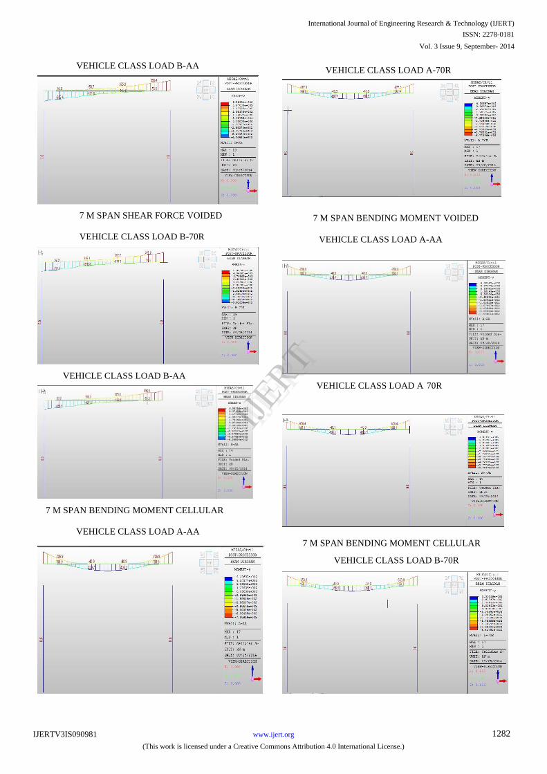
VEHICLE CLASS LOAD B-AA
7 M SPAN SHEAR FORCE VOIDED
VEHICLE CLASS LOAD B-70R
VEHICLE CLASS LOAD B-AA
7 M SPAN BENDING MOMENT CELLULAR
VEHICLE CLASS LOAD A-AA
VEHICLE CLASS LOAD A 70R
VEHICLE CLASS LOAD A-AA
VEHICLE CLASS LOAD A-70R
7 M SPAN BENDING MOMENT VOIDED
7 M SPAN BENDING MOMENT CELLULAR
VEHICLE CLASS LOAD B-70R
International Journal of Engineering Research & Technology (IJERT)
IJERT
IJERT
ISSN: 2278-0181
www.ijert.orgIJERTV3IS090981
(This work is licensed under a Creative Commons Attribution 4.0 International License.)
Vol. 3 Issue 9, September- 2014
1282
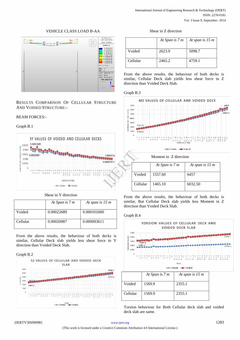
RESULTS COMPARISON OF CELLULAR STRUCTURE
AND VOIDED STRUCTURE:-
BEAM FORCES:-
Graph B.1
Shear in Y direction
At Span is 7 m At span is 15 m
Voided 0.00022689 0.000101600
Cellular 0.00020087 0.000093611
From the above results, the behaviour of both decks is
similar, Cellular Deck slab yields less shear force in Y
direction than Voided Deck Slab.
Graph B.2
Shear in Z direction
At Span is 7 m
At span is 15 m
Voided
2623.9
5098.7
Cellular
2465.2
4759.1
From the above results, the behaviour of both decks is
similar, Cellular Deck slab yields less shear force in Z
direction than Voided Deck Slab.
Graph B.3
Moment in Z direction
At Span is 7 m
At span is 15 m
Voided
1557.60
6457
Cellular
1465.10
6032.50
From the above results, the behaviour of both decks is
similar, But Cellular Deck slab yields less Moment in Z
direction than Voided Deck Slab.
Graph B.4
At Span is 7 m At span is 15 m
Voided 1569.9 2355.1
Cellular 1569.9 2355.1
Torsion behaviour for Both Cellular deck slab and voided
deck slab are same.
VEHICLE CLASS LOAD B-AA
International Journal of Engineering Research & Technology (IJERT)
IJERT
IJERT
ISSN: 2278-0181
www.ijert.orgIJERTV3IS090981
(This work is licensed under a Creative Commons Attribution 4.0 International License.)
Vol. 3 Issue 9, September- 2014
1283
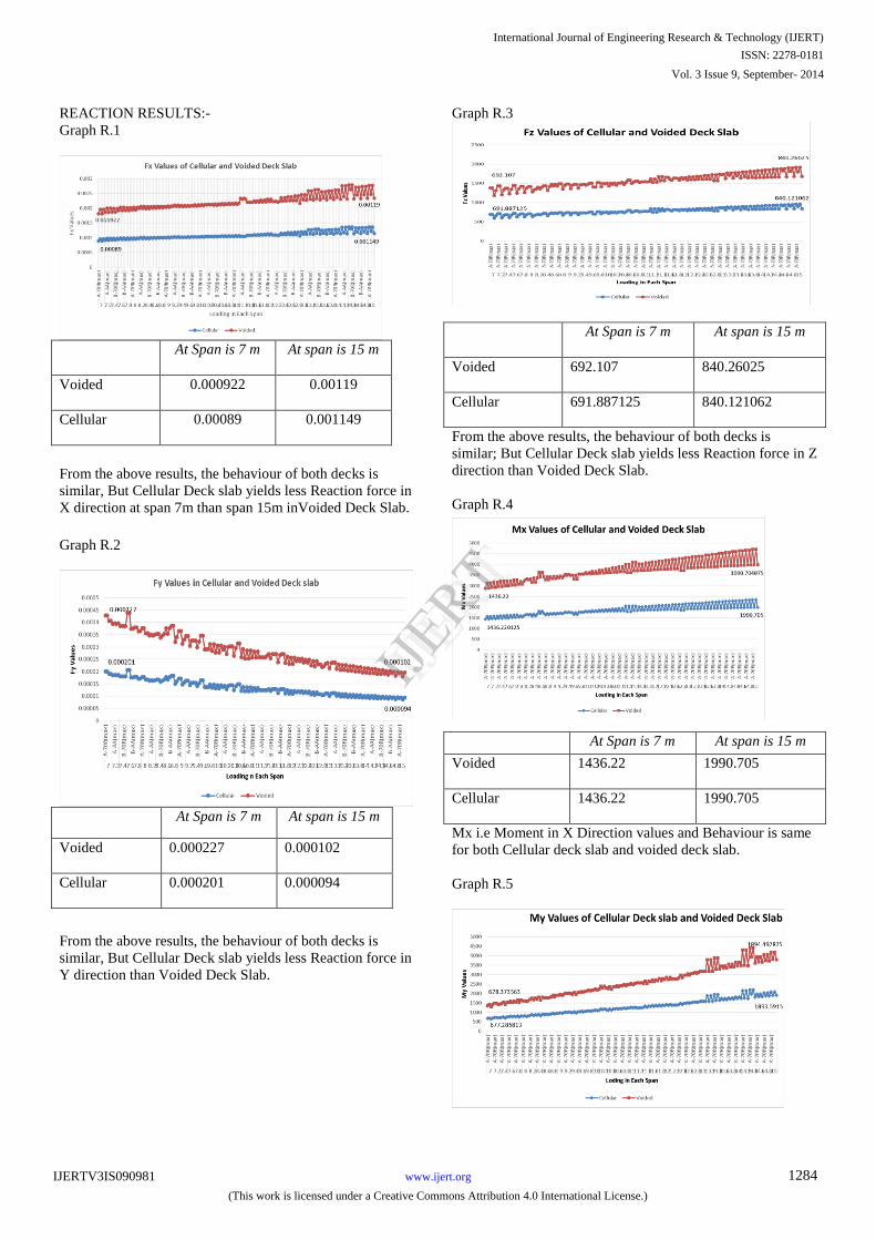
REACTION RESULTS:-
Graph R.1
At Span is 7 m At span is 15 m
Voided 0.000922 0.00119
Cellular 0.00089 0.001149
From the above results, the behaviour of both decks is
similar, But Cellular Deck slab yields less Reaction force in
X direction at span 7m than span 15m inVoided Deck Slab.
Graph R.2
At Span is 7 m At span is 15 m
Voided 0.000227 0.000102
Cellular 0.000201 0.000094
From the above results, the behaviour of both decks is
similar, But Cellular Deck slab yields less Reaction force in
Y direction than Voided Deck Slab.
Graph R.3
At Span is 7 m At span is 15 m
Voided 692.107 840.26025
Cellular 691.887125 840.121062
From the above results, the behaviour of both decks is
similar; But Cellular Deck slab yields less Reaction force in Z
direction than Voided Deck Slab.
Graph R.4
At Span is 7 m At span is 15 m
Voided 1436.22 1990.705
Cellular 1436.22 1990.705
Mx i.e Moment in X Direction values and Behaviour is same
for both Cellular deck slab and voided deck slab.
Graph R.5
International Journal of Engineering Research & Technology (IJERT)
IJERT
IJERT
ISSN: 2278-0181
www.ijert.orgIJERTV3IS090981
(This work is licensed under a Creative Commons Attribution 4.0 International License.)
Vol. 3 Issue 9, September- 2014
1284
At Span is 7 m
At span is 15 m
Voided
678.375
1894.497
Cellular
677.285
1893.5915
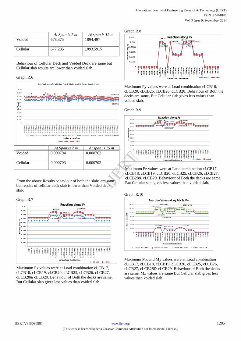
Behaviour of Cellular Deck and Voided Deck are same but
Cellular slab results are lower than voided slab.
Graph R.6
At Span is 7 m
At span is 15 m Voided
0.000794
0.000762
Cellular
0.000703
0.000702
From the above Results behaviour of both the slabs are same,
but results of cellular deck slab is lower than Voided deck
slab.
Graph R.7
Maximum Fx values were at Load combination cLCB17,
cLCB18, cLCB19, cLCB20, cLCB25, cLCB26, cLCB27,
cLCB28& cLCB29. Behaviour of Both the decks are same,
But Cellular slab gives less values than voided slab.
Graph R.8
Maximum Fy values were at Load combination cLCB16,
cLCB20, cLCB25, cLCB26, cLCB28. Behaviour of Both the
decks are same, But Cellular slab gives less values than
voided slab.
Graph R.9
Maximum Fz values were at Load combination cLCB17,
cLCB18, cLCB19, cLCB20, cLCB25, cLCB26, cLCB27,
cLCB28& cLCB29. Behaviour of Both the decks are same,
But Cellular slab gives less values than voided slab.
Graph R.10
Maximum Mx and My values were at Load combination
cLCB17, cLCB18, cLCB19, cLCB20, cLCB25, cLCB26,
cLCB27, cLCB28& cLCB29. Behaviour of Both the decks
are same, Mx values are same But Cellular slab gives less
values than voided slab.
International Journal of Engineering Research & Technology (IJERT)
IJERT
IJERT
ISSN: 2278-0181
www.ijert.orgIJERTV3IS090981
(This work is licensed under a Creative Commons Attribution 4.0 International License.)
Vol. 3 Issue 9, September- 2014
1285
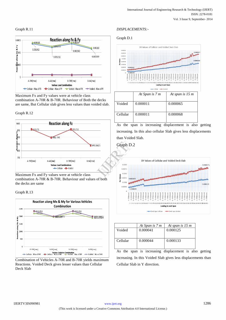
Graph R.11
Maximum Fx and Fy values were at vehicle class
combination A-70R & B-70R. Behaviour of Both the decks
are same, But Cellular slab gives less values than voided slab.
Graph R.12
Maximum Fx and Fy values were at vehicle class
combination A-70R & B-70R. Behaviour and values of both
the decks are same
Graph R.13
Combination of Vehicles A-70R and B-70R yields maximum
Reactions. Voided Deck gives lesser values than Cellular
Deck Slab
DISPLACEMENTS:-
Graph D.1
At Span is 7 m At span is 15 m
Voided 0.000011 0.000065
Cellular 0.000011 0.000068
As the span is increasing displacement is also getting
increasing. In this also cellular Slab gives less displacements
than Voided Slab.
Graph D.2
At Span is 7 m At span is 15 m
Voided 0.000041 0.000125
Cellular 0.000044 0.000133
As the span is increasing displacement is also getting
increasing. In this Voided Slab gives less displacements than
Cellular Slab in Y direction.
International Journal of Engineering Research & Technology (IJERT)
IJERT
IJERT
ISSN: 2278-0181
www.ijert.orgIJERTV3IS090981
(This work is licensed under a Creative Commons Attribution 4.0 International License.)
Vol. 3 Issue 9, September- 2014
1286
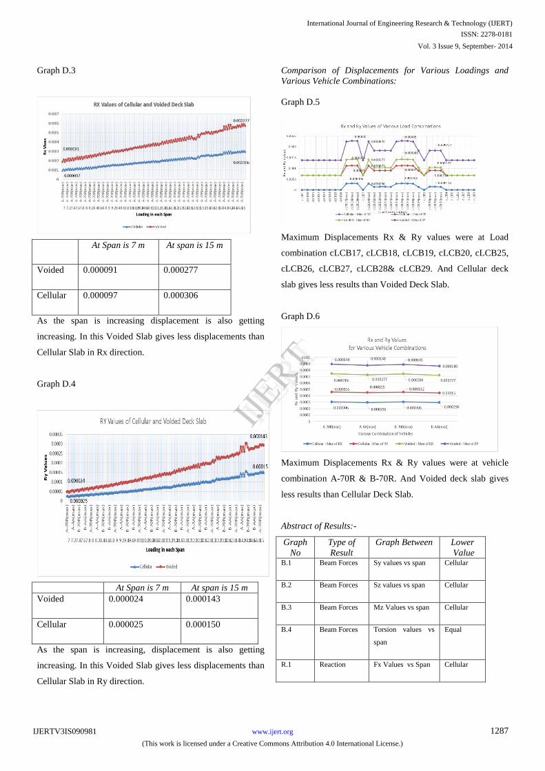
Graph D.3
At Span is 7 m At span is 15 m
Voided 0.000091 0.000277
Cellular 0.000097 0.000306
As the span is increasing displacement is also getting
increasing. In this Voided Slab gives less displacements than
Cellular Slab in Rx direction.
Graph D.4
At Span is 7 m At span is 15 m
Voided 0.000024 0.000143
Cellular 0.000025 0.000150
As the span is increasing, displacement is also getting
increasing. In this Voided Slab gives less displacements than
Cellular Slab in Ry direction.
Comparison of Displacements for Various Loadings and
Various Vehicle Combinations:
Graph D.5
Maximum Displacements Rx & Ry values were at Load
combination cLCB17, cLCB18, cLCB19, cLCB20, cLCB25,
cLCB26, cLCB27, cLCB28& cLCB29. And Cellular deck
slab gives less results than Voided Deck Slab.
Graph D.6
Maximum Displacements Rx & Ry values were at vehicle
combination A-70R & B-70R. And Voided deck slab gives
less results than Cellular Deck Slab.
Abstract of Results:-
Graph
No
Type of
Result
Graph Between Lower
Value B.1 Beam Forces Sy values vs span Cellular
B.2 Beam Forces Sz values vs span Cellular
B.3 Beam Forces Mz Values vs span Cellular
B.4 Beam Forces Torsion values vs
span
Equal
R.1 Reaction Fx Values vs Span Cellular
International Journal of Engineering Research & Technology (IJERT)
IJERT
IJERT
ISSN: 2278-0181
www.ijert.orgIJERTV3IS090981
(This work is licensed under a Creative Commons Attribution 4.0 International License.)
Vol. 3 Issue 9, September- 2014
1287
R.2 Reaction Fy Values vs Span Cellular
R.3 Reaction Fz Values vs Span Cellular
R.4 Reaction Mx Values vs Span Equal
R.5 Reaction My Values vs Span Cellular
R.6 Reaction Mz Values vs Span Cellular
R.7 Reaction Fx vs Load
combinations
Cellular
R.8 Reaction Fy vs Load
combinations
Cellular
Graph
No
Type of
Result
Graph Between Lower
Value R.9 Reaction Fz vs Load
combinations
Cellular
R.10 Reaction Mx & My Values vs
Load Combination
Cellular
R.11 Reaction Fx & Fy Values vs
Vehicles
combination
Cellular
R.12 Reaction Fz Values vs
Vehicles
combination
Equal
R.13 Reaction Mx & My Values vs
Vehicles
combination
D.1 Displacements Dx Values vs span Cellular
D.2 Displacements Dy Values vs span Voided
D.3 Displacements Rx Values vs span Voided
D.4 Displacements Ry Values vs span Voided
D.5 Displacements Rx, Ry Values vs
Load combination
Cellular
D.6 Displacements Rx, Ry Values vs
Vehicles
combination
Voided
CONCLUSIONS
The object of this paper is the study of the representation of
the Voided and Cellular slab models with which different
spans of bridge decks can be represented for various Vehicle
class Combination and Various Load Combinations. The
purpose of the work is to contribute to this type of approach
through the introduction of the effects of Shape constraint
and voided ratio to depth of deck and depth of void, which is
usually neglected.
The introduction of these effects in analysis is obtained by
Analyzing series of different spans using Midas civil.
From the analysis comparison, it’s appeared how the use of
different shapes effects the Bending Moments, Shear forces,
Reactions and displacements results from 7.0m to 15.0m span
with a interval of 0.2m.
By Observing the results the following variations are
occurred:-
1. Beam Forces of cellular deck slab gives lesser values
in Sy, Sz and Mz than voided deck slab.
2. Beam forces of Torsion is same for both decks.
3. Reactions of cellular deck slab Fx, Fy and Fz values
gives lesser values than voided deck slab.
4. Reactions of Mx values are same for both decks.
5. Reactions of cellular deck slab gives lesser results in
My,Mz values than voided deck slab when compared
with various load combination and various class
Vehicles.
6. Displacements of voided deck slab gives lesser values in
Dy,Rx, Ry than cellular deck slab when compared with
various load combination and various class Vehicles.
7. Displacements of cellular deck slab gives lesser
values in Dx,Rx,Ry values than voided deck slab when
compared with various load combination and various
class Vehicles.
When compared with cellular deck slab only voided deck
slab have lesser displacements which is very neglible. So
rectangular shape cellular deck is best in withstanding more
load than voided slab with same dimensions.
REFERENCES:-
1. IRC 6:2010 Standard Specifications And Code Of Practice For
Road Bridges
2. IRC 21:2000 Standard Specifications And Code Of Practice
For Rcc Road Bridges
3. IRC:SP:64-2005 Guidelines for the analysis and design of
Cast-in-place voided slab superstructure
4. IRC:18:2000 Design criteria for Prestressed concrete road
bridges (Post-Tensioned Concrete)
5. Parametric Study of R.C.C Voided and Solid Flat Plate Slab
using SAP 2000 by
6. SaifeeBhagat1 ,Dr. K. B. Parikh in IOSR Journal of
Mechanical and Civil Engineering (IOSR-JMCE) e-ISSN:
2278-1684,p-ISSN: 2320-334X, Volume 11, Issue 2 Ver. VI
(Mar- Apr. 2014), PP 12-16
International Journal of Engineering Research & Technology (IJERT)
IJERT
IJERT
ISSN: 2278-0181
www.ijert.orgIJERTV3IS090981
(This work is licensed under a Creative Commons Attribution 4.0 International License.)
Vol. 3 Issue 9, September- 2014
1288

7. Torsional behavior and constancy of curved box girder super
structures by Ashish B Sarode and G R Vesmawala in TARCE
–Vol 1 No.2 July-December 2012.
8. Finite Element Modelling of Continuous Posttensioned Voided
Slab Bridges by Raja Sen, Mohan Issa, Xianghong Sun and
Antonie Gergess in J.Struct.Eng. 1994.120:651-667.
9. Bridge Super Structure by N. RajaGopalan
10. “Design of Bridges” by Krishnaraju, Third Edition, Oxford and
IBH Publishing Co. Pvt. Ltd., New Delhi.
11. Essentials of Bridge Engineering sixth edition by D. Johnson
Victor:
International Journal of Engineering Research & Technology (IJERT)
IJERT
IJERT
ISSN: 2278-0181
www.ijert.orgIJERTV3IS090981
(This work is licensed under a Creative Commons Attribution 4.0 International License.)
Vol. 3 Issue 9, September- 2014
1289