Embed Size (px)
Citation preview
Analysis of Video Streaming with SP and SI Framesin UMTS Mobile Networks
Luca Superiori and Markus Rupp∗
Institute of Communications and RFEngineering,
Vienna University of TechnologyGusshausstrasse 25/389A-1040 Vienna, Austria
{lsuper,mrupp}@nt.tuwien.ac.at
Wolfgang Karnermobilkom austria
Obere Donaustrasse 21A-1020 Vienna, Austria
ABSTRACTIn this paper we discuss possible benefits of transmitting SIframes as an error resilience tool in UMTS video stream-ing. SP and SI frames can be used to stop temporal errorpropagation, as an alternative to the regular insertion of Iframes. Since their application relays on feedback informa-tion from the mobile equipment, different delay scenarioshave been investigated. The performed transmission simu-lations show enhancement of the rate-distortion behaviourwhen using SP and SI frames with reduced feedback times.The error traces were measured at transport block level ina live UMTS mobile network.
KeywordsVideo Streaming, UMTS, H.264/AVC, SP and SI Frames
1. INTRODUCTIONH.264/AVC [1] is the state-of-the-art video codec jointly
standardized by ISO/MPEG (International Standard Orga-nization Moving Picture Expert Group) and ITU/VCEG(International Telecommunication Unit Video Coding Ex-pert Group) in 2003. The standard has been organized indifferent profiles, each designed for specific classes of appli-cations (such as unicast, broadcast or storage) and definesa set of enabled features.
The 3GPP (3rd Generation Partnership Project) is the in-ternational association that defines the specifications of thethird generation mobile phone system. In [2] the 3GPP de-fines the H.264/AVC in its baseline profile as optional videocodec that has to be supported by standard compliant mo-bile devices. The baseline profile is the most basic one and
∗The authors thank mobilkom austria AG for technical andfinancial support of this work. The views expressed in thispaper are those of the authors and do not necessarily reflectthe views within mobilkom austria AG.
Permission to make digital or hard copies of all or part of this work forpersonal or classroom use is granted without fee provided that copies arenot made or distributed for profit or commercial advantage and that copiesbear this notice and the full citation on the first page. To copy otherwise, torepublish, to post on servers or to redistribute to lists, requires prior specificpermission and/or a fee.MoMM 2009 December 14–16, 2009, Kuala Lumpur, Malaysia.Copyright 2009 ACM 978-1-60558-659-5/09/0012 ...$10.00.
its set of functionalities are included by all the other profiles.It has been selected because of the target device capabilities(mobile phones with limited computational power) and be-cause of the transmission characteristics (unicast with strongdelay constraints).
The baseline profile allows two kind of frames. The Intra(I) predicted frames exploit the spatial correlation of a singlepicture. The frame is segmented into macroblocks and eachmacroblock is then encoded using the neighbouring ones asprediction’s reference. The Inter (P) predicted frames areencoded taking advantage of the similarities between con-secutive pictures. The size of an encoded frame dependsstrongly on the prediction type used. The spatial predic-tion is much less effective than the temporal one, thereforeit requires more bits for correcting the prediction. For thisreason, a video stream consists of a group of inter encodedframes interleaved, with a given frequency, by intra encodedframes. The distance, in frames, between two consecutive Iframes is defined as Group Of Picture (GOP).
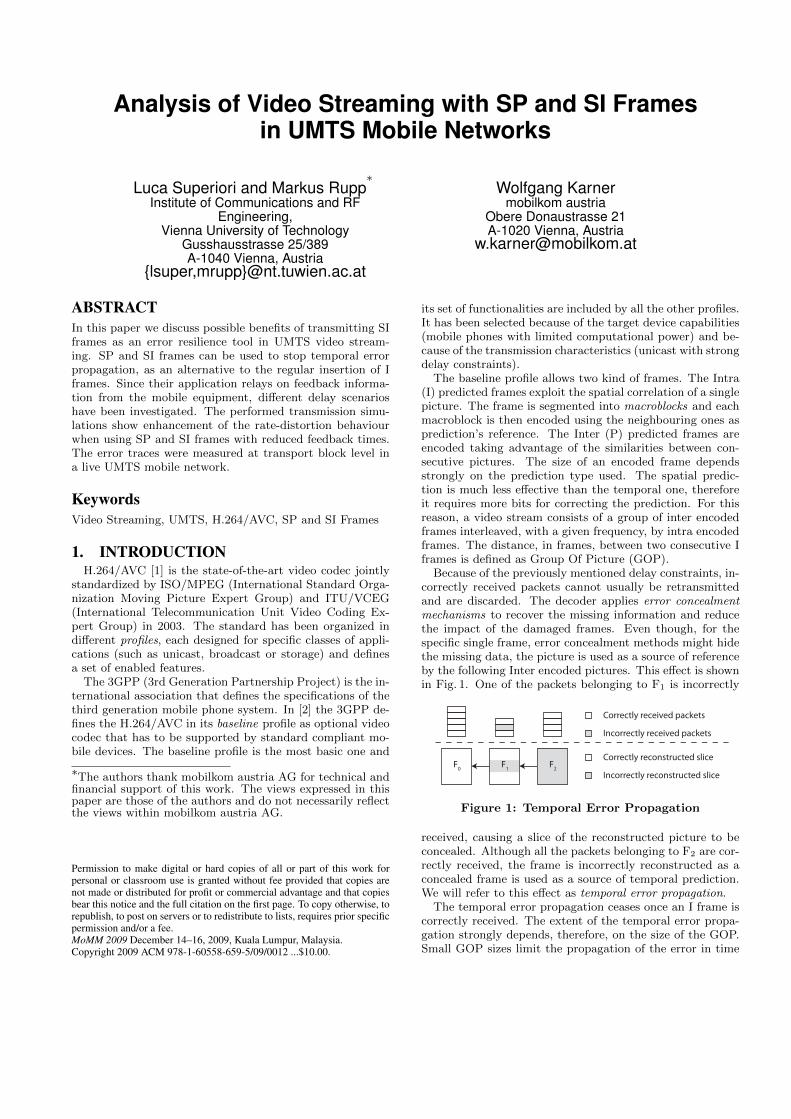
Because of the previously mentioned delay constraints, in-correctly received packets cannot usually be retransmittedand are discarded. The decoder applies error concealmentmechanisms to recover the missing information and reducethe impact of the damaged frames. Even though, for thespecific single frame, error concealment methods might hidethe missing data, the picture is used as a source of referenceby the following Inter encoded pictures. This effect is shownin Fig. 1. One of the packets belonging to F1 is incorrectly
F0 F1 F2
Correctly received packets
Incorrectly received packets
Correctly reconstructed slice
Incorrectly reconstructed slice
Figure 1: Temporal Error Propagation
received, causing a slice of the reconstructed picture to beconcealed. Although all the packets belonging to F2 are cor-rectly received, the frame is incorrectly reconstructed as aconcealed frame is used as a source of temporal prediction.We will refer to this effect as temporal error propagation.
The temporal error propagation ceases once an I frame iscorrectly received. The extent of the temporal error propa-gation strongly depends, therefore, on the size of the GOP.Small GOP sizes limit the propagation of the error in time
but result in increasing stream size as shown in Fig. 2.
250 260 270 280 290 300 310 32025
30
35
Bitrate [kb/s]
Y−PS
NR
[dB]
1% IP Error rate
3% IP Error rate
5% IP Error rateGOP = 10 frames
GOP = 100 frames
Figure 2: Rate-distortion behavior depending on theGOP size
In this article we consider the application of the SI framesin mobile environments to reduce the effect of the temporalerror propagation. The SI frames are special intra encodedframes, that can be sent in place of SP frames, special en-coded P frames, in case the terminal reports that an errorhas occurred. Although the SP and SI frames are not yetsupported by the profile suggested in [2], we performed ananalysis aimed at measuring possible benefits deriving fromtheir application.
The paper is organized as follows. In Section 2 the SIand SP frames are briefly explained. Section 3 describes theconsidered channel realisation. The simulation setup is dis-cussed in Section 4. Section 5 presents the performed anal-ysis in terms of rate distortion. Section 6 offers conclusiveremarks.
2. SP AND SI FRAMESThe temporal error propagation affects the inter encoded
frames following the incorrectly received frame. It is stoppedby the next Intra encoded frame, since it does not containreference to the previous pictures. Moreover, this is trueonly if the Intra frame empties the reference pictures bufferor if the size of the buffer itself has been set equal to one.
The position of the I frames is set during the encodingand cannot be modified. The GOP size might be constantor, for some specific applications, variable. In case of suddenscene changes, in fact, the encoder might find beneficial toencode the whole frame as Intra, since the previous framesdo not represent an efficient source of prediction.
Also considering the possibility of a feedback mechanism,in case temporal error propagation has been detected an Iframe cannot be sent in place of a P frame and substituteit. The macroblock reconstruction is extremely sensitive tothe correctness of the prediction source. After the Intra, orInter, prediction, each 4 × 4 subblock of the original mac-roblock is subtracted from the correspondent one of the bestfound prediction. The residual block is then transformed bymeans of an horizontal and vertical Direct Cosine Trans-formation (DCT) and quantized, obtaining the coefficientsmatrix. The coefficients matrix is entropic encoded and usedat the decoder side for improving the prediction using theinverse quantization and inverse DCT transformations andthen summing up the result to the prediction. In order notto introduce drifts between the encoder and the decoder,the two predicted block have to be the same. For this rea-son, at the encoder side the reconstructed blocks are usedfor prediction in place of the, available, original blocks.
If an I frame is scheduled for transmission in place of the
original P frame without being considered at the encoderside, the following frames are using a wrong source of predic-tion. This cause the incorrect reconstruction of the pictures,as the decoder and the encoder are using different sourcesof prediction.
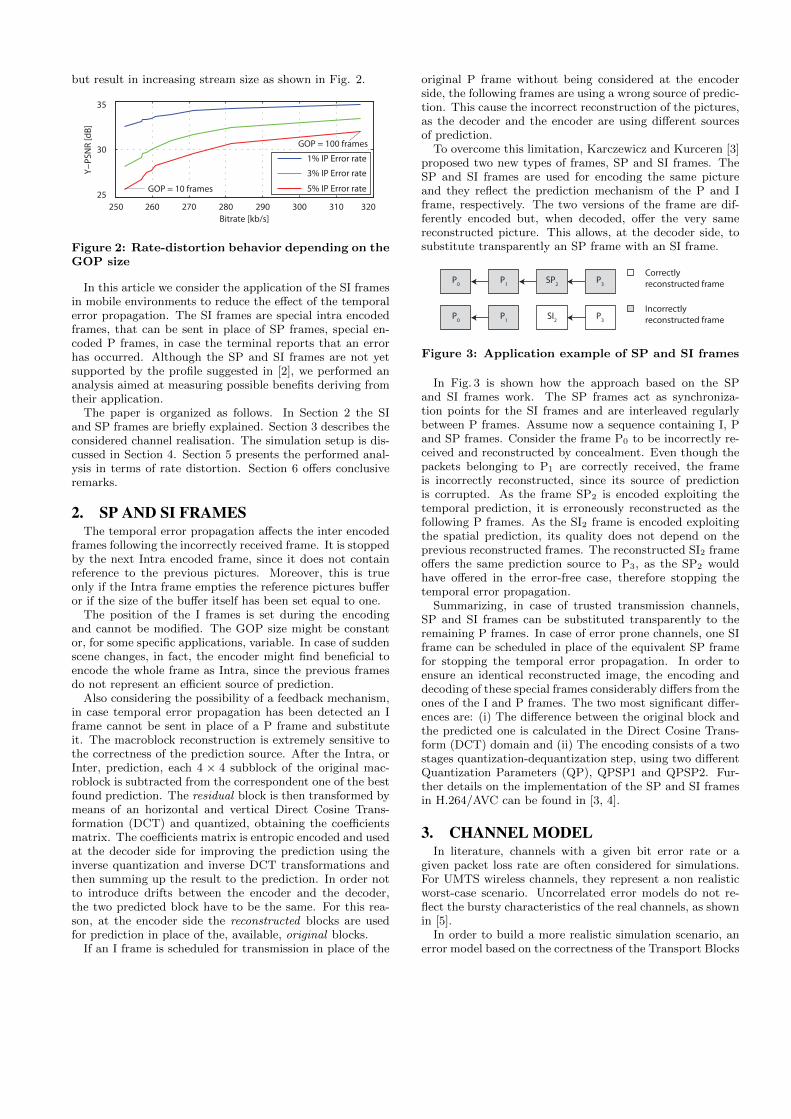
To overcome this limitation, Karczewicz and Kurceren [3]proposed two new types of frames, SP and SI frames. TheSP and SI frames are used for encoding the same pictureand they reflect the prediction mechanism of the P and Iframe, respectively. The two versions of the frame are dif-ferently encoded but, when decoded, offer the very samereconstructed picture. This allows, at the decoder side, tosubstitute transparently an SP frame with an SI frame.
P1
Correctly reconstructed frame
Incorrectlyreconstructed frame
SP2 P3P0
SI2 P3P1P0
Figure 3: Application example of SP and SI frames
In Fig. 3 is shown how the approach based on the SPand SI frames work. The SP frames act as synchroniza-tion points for the SI frames and are interleaved regularlybetween P frames. Assume now a sequence containing I, Pand SP frames. Consider the frame P0 to be incorrectly re-ceived and reconstructed by concealment. Even though thepackets belonging to P1 are correctly received, the frameis incorrectly reconstructed, since its source of predictionis corrupted. As the frame SP2 is encoded exploiting thetemporal prediction, it is erroneously reconstructed as thefollowing P frames. As the SI2 frame is encoded exploitingthe spatial prediction, its quality does not depend on theprevious reconstructed frames. The reconstructed SI2 frameoffers the same prediction source to P3, as the SP2 wouldhave offered in the error-free case, therefore stopping thetemporal error propagation.
Summarizing, in case of trusted transmission channels,SP and SI frames can be substituted transparently to theremaining P frames. In case of error prone channels, one SIframe can be scheduled in place of the equivalent SP framefor stopping the temporal error propagation. In order toensure an identical reconstructed image, the encoding anddecoding of these special frames considerably differs from theones of the I and P frames. The two most significant differ-ences are: (i) The difference between the original block andthe predicted one is calculated in the Direct Cosine Trans-form (DCT) domain and (ii) The encoding consists of a twostages quantization-dequantization step, using two differentQuantization Parameters (QP), QPSP1 and QPSP2. Fur-ther details on the implementation of the SP and SI framesin H.264/AVC can be found in [3, 4].
3. CHANNEL MODELIn literature, channels with a given bit error rate or a
given packet loss rate are often considered for simulations.For UMTS wireless channels, they represent a non realisticworst-case scenario. Uncorrelated error models do not re-flect the bursty characteristics of the real channels, as shownin [5].
In order to build a more realistic simulation scenario, anerror model based on the correctness of the Transport Blocks
(TB) is used. The protocol architecture for video streamingover UMTS networks is drawn in Fig. 4. The entities pro-
IP UDP RTP NAL Unit
RLC
MAC
CRC
RLC - PDU
TB
Figure 4: Protocol Stack
duced by the video encoder, the Network Abstraction LayerUnit (NALU), are further encapsulated into the Real TimeProtocol (RTP) [6]. To each RTP packet an Universal Data-gram Protocol (UDP) [7] as well as an Internet Protocol (IP)[8] header are further attached. This results in a 40 bytesprotocol overhead. The IP packets are then segmented intoRadio Link Control (RLC) Protocol Data Units (PDUs).For the bearer used for video streaming, it is suggested anRLC payload of 40 bytes. These Transport Blocks (TB) arethen mapped onto the transport channel by the MediumAccess Control (MAC). To evaluate the correctness of theMAC packets at the receiver, a Cyclic Redundancy Check(CRC) is attached.
For the measurements, a UDP data stream with bit ratesof up to 360 kb/s in downlink was sent from a PC overthe UMTS network to a notebook using a UMTS terminalas a modem via a USB connection. In Fig. 5 is given aschematic illustration of the setup for the measurements inthe live networks. In the notebook, the traces were recorded
Mobilephone Laptop
NodeB RNC SGSN GGSN
ServerPC
Internet
UniversityLAN
UTRAN
UDP Data
Figure 5: Measurement setup
using the TEMS investigation software by Ericsson. TheCRC information of the received TBs were parsed from thetraces and used for the analysis of the UMTS link errorcharacteristics.
4. SIMULATION SETUPThe scope of the investigation is to measure the perfor-
mance of the application of SI and SP frames in H.264/AVCwith respect to the classical I-P-P scheme. We simulate thetransmission of streams encoded with both strategies overthe channel realizations described in Section 3.
4.1 Generation of the encoded sequencesIn order to generate the encoded sequences, the standard
reference software JM [9] ver. 11.0 has been used. Although
at the time of the submission the ver. 15.0 of the software wasavailable, it was not used as the implementation of SP andSI frames in the newer versions is known to be not properlyworking.
A football video sequence in DVD format consisting ofaround 1000 frames has been encoded considering the typi-cal configuration of unicast video streaming over third gen-eration mobile networks. The most stringent constraint isrepresented by the bandwidth that is limited to 180 kb/s. Tomatch this restriction, the resolution of the video has beenreduced to QVGA (Quarter Video Graphic Array), 320×240pixels (typical for most mobile phones). The sequence is alsodecimated in time, reducing the frame rate (fr) from 30 to15 frames per second (f/s). The compression level is tunedby means of the quantization parameter, having impact onboth the resulting quality and datarate.
For the I-P-P scheme, 17 different GOP sizes varying from2 to 50 frames have been considered. The GOP size stronglyaffects datarate, being the encoded I frames much biggerthan the P frames. Because of the different encoding mech-anism, even if the same QP for both the I frames and theP frames has been used, the quality of the Intra predictedframes was, in average, higher than the one of the Inter en-coded frames. That makes the error free sequence quality afunction of the GOP size, introducing an unnecessary com-plexity in the investigation. In order to make the quality ofthe I-P-P sequence not dependent on the GOP size a QP of35 for the P frames and QP 37 for the I frames has beenused.
For the I-P-S sequences, a single I frames was encoded atthe beginning of the sequence. Two sets of sequences havebeen generated for different S-frames Distances (SD), onecontaining I-P-SP frames and one containing I-P-SI frames.
As for the I-P-P scheme, the same 17 different distancesfrom 2 to 50 were considered. The quality and the size of theSP and SI frames strongly depend on the selected QPSP1and QPSP2. At this step, without knowing the probabilityof needing an SI frame, the both QPSPs have been set to 33.The QPSP of the SP/SI frames has been set slightly smallerthan the one of the P frames in order to guarantee the samequality to the reconstructed frames.
4.2 Transmission of the sequencesAs suggested in [10] the packet size of the I and P frames
was set to 750 bytes, offering a good compromise betweenheader overhead and impact of a lost packet. The bigger thepacket, in fact, the less efficient the error concealment.
The SP and SI frames were not sliced into packets sincethe current implementation of the JM software does not sup-port a fixed size of SP and SI frames in Byte. In order toguarantee the same reconstructed picture, the encoding ofthe SI frame should be aware of the slice segmentation of SPframes in order to tune the allowed prediction modes, andvice versa.
The transmission was simulated inserting the errors (mea-sured as described in Section 3) at transport block level.Each RTP packet of the stream has been discarded in caseone of its transport blocks was marked as flawed. For the I-P-P scheme, a damaged packet was removed from the videofile and the standard concealment strategies of JM were usedto recover the missing information.
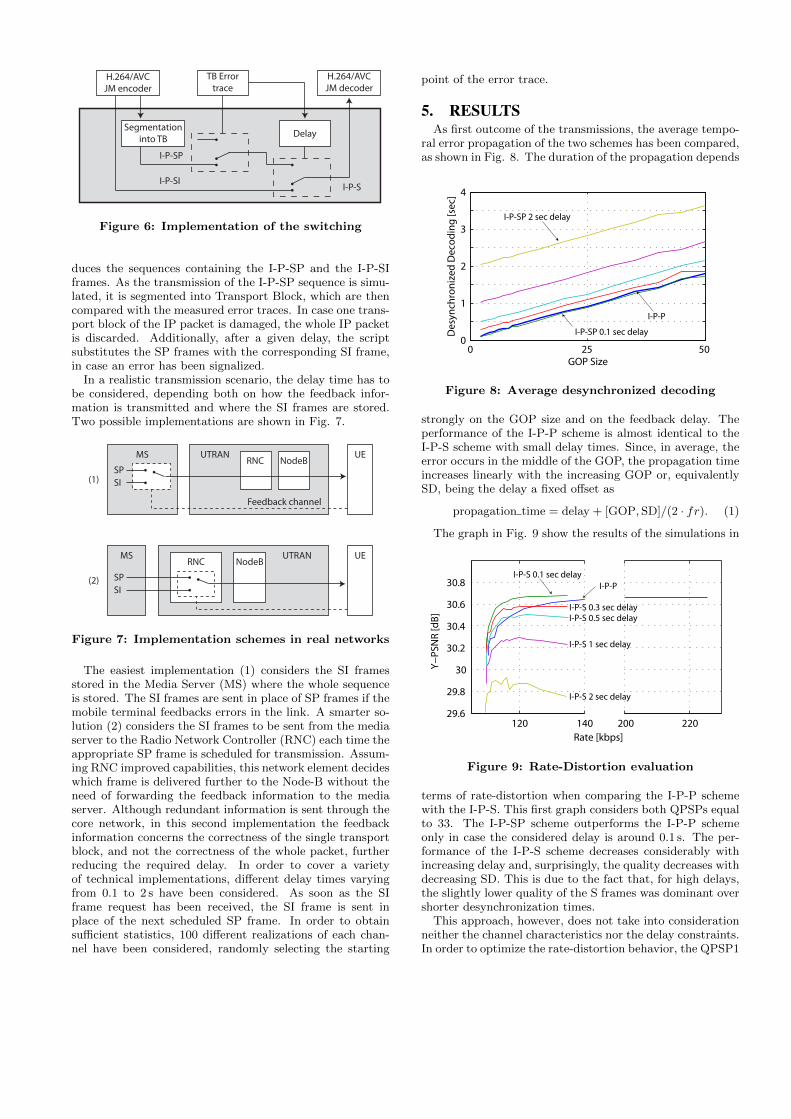
For the I-P-S scheme, a switching mechanism was imple-mented as shown in Fig. 6. The H.264/AVC encoder pro-
H.264/AVCJM encoder
TB Errortrace
Segmentationinto TB Delay
H.264/AVCJM decoder
I-P-SP
I-P-SII-P-S
Figure 6: Implementation of the switching
duces the sequences containing the I-P-SP and the I-P-SIframes. As the transmission of the I-P-SP sequence is simu-lated, it is segmented into Transport Block, which are thencompared with the measured error traces. In case one trans-port block of the IP packet is damaged, the whole IP packetis discarded. Additionally, after a given delay, the scriptsubstitutes the SP frames with the corresponding SI frame,in case an error has been signalized.
In a realistic transmission scenario, the delay time has tobe considered, depending both on how the feedback infor-mation is transmitted and where the SI frames are stored.Two possible implementations are shown in Fig. 7.
SPSI
MSRNC
UTRAN
SPSI
RNC
NodeB
Feedback channel
UTRANMSNodeB
UE
UE
(1)
(2)
Figure 7: Implementation schemes in real networks
The easiest implementation (1) considers the SI framesstored in the Media Server (MS) where the whole sequenceis stored. The SI frames are sent in place of SP frames if themobile terminal feedbacks errors in the link. A smarter so-lution (2) considers the SI frames to be sent from the mediaserver to the Radio Network Controller (RNC) each time theappropriate SP frame is scheduled for transmission. Assum-ing RNC improved capabilities, this network element decideswhich frame is delivered further to the Node-B without theneed of forwarding the feedback information to the mediaserver. Although redundant information is sent through thecore network, in this second implementation the feedbackinformation concerns the correctness of the single transportblock, and not the correctness of the whole packet, furtherreducing the required delay. In order to cover a varietyof technical implementations, different delay times varyingfrom 0.1 to 2 s have been considered. As soon as the SIframe request has been received, the SI frame is sent inplace of the next scheduled SP frame. In order to obtainsufficient statistics, 100 different realizations of each chan-nel have been considered, randomly selecting the starting
point of the error trace.
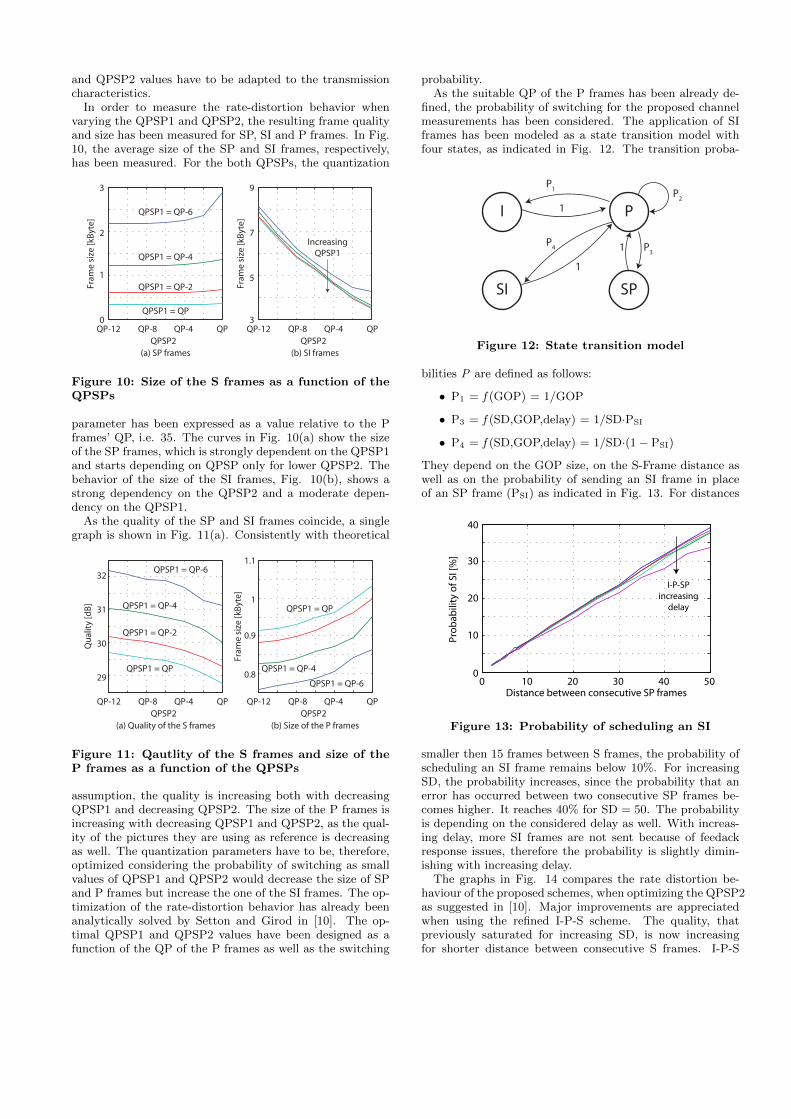
5. RESULTSAs first outcome of the transmissions, the average tempo-
ral error propagation of the two schemes has been compared,as shown in Fig. 8. The duration of the propagation depends
0 25 500
1
2
3
4
GOP Size
Des
ynch
ron
ized
Dec
od
ing
[sec
]
I-P-P
I-P-SP 0.1 sec delay
I-P-SP 2 sec delay
Figure 8: Average desynchronized decoding
strongly on the GOP size and on the feedback delay. Theperformance of the I-P-P scheme is almost identical to theI-P-S scheme with small delay times. Since, in average, theerror occurs in the middle of the GOP, the propagation timeincreases linearly with the increasing GOP or, equivalentlySD, being the delay a fixed offset as
propagation time = delay + [GOP, SD]/(2 ⋅ fr). (1)
The graph in Fig. 9 show the results of the simulations in
120 140 200 22029.6
29.8
30
30.2
30.4
30.6
30.8
Rate [kbps]
Y−PS
NR
[dB]
I-P-S 0.1 sec delay
I-P-S 0.3 sec delayI-P-S 0.5 sec delay
I-P-S 1 sec delay
I-P-S 2 sec delay
I-P-P
Figure 9: Rate-Distortion evaluation
terms of rate-distortion when comparing the I-P-P schemewith the I-P-S. This first graph considers both QPSPs equalto 33. The I-P-SP scheme outperforms the I-P-P schemeonly in case the considered delay is around 0.1 s. The per-formance of the I-P-S scheme decreases considerably withincreasing delay and, surprisingly, the quality decreases withdecreasing SD. This is due to the fact that, for high delays,the slightly lower quality of the S frames was dominant overshorter desynchronization times.
This approach, however, does not take into considerationneither the channel characteristics nor the delay constraints.In order to optimize the rate-distortion behavior, the QPSP1
and QPSP2 values have to be adapted to the transmissioncharacteristics.
In order to measure the rate-distortion behavior whenvarying the QPSP1 and QPSP2, the resulting frame qualityand size has been measured for SP, SI and P frames. In Fig.10, the average size of the SP and SI frames, respectively,has been measured. For the both QPSPs, the quantization
0
1
2
3
Fram
e si
ze [k
Byte
]
QPSP2
3
5
7
9
QPQP-4QP-8QP-12QPSP2
QPQP-4QP-8QP-12
Fram
e si
ze [k
Byte
]
QPSP1 = QP
QPSP1 = QP-2
QPSP1 = QP-4
QPSP1 = QP-6
IncreasingQPSP1
(a) SP frames (b) SI frames
Figure 10: Size of the S frames as a function of theQPSPs
parameter has been expressed as a value relative to the Pframes’ QP, i.e. 35. The curves in Fig. 10(a) show the sizeof the SP frames, which is strongly dependent on the QPSP1and starts depending on QPSP only for lower QPSP2. Thebehavior of the size of the SI frames, Fig. 10(b), shows astrong dependency on the QPSP2 and a moderate depen-dency on the QPSP1.
As the quality of the SP and SI frames coincide, a singlegraph is shown in Fig. 11(a). Consistently with theoretical
QPSP2QPQP-4QP-8QP-12
QPSP2QPQP-4QP-8QP-12
Fram
e si
ze [k
Byte
]
(a) Quality of the S frames (b) Size of the P frames
QPSP1 = QP
QPSP1 = QP-2
QPSP1 = QP-4
QPSP1 = QP-6
29
30
31
32
Qua
lity
[dB]
QPSP1 = QP-6
QPSP1 = QP-4
QPSP1 = QP
0.8
0.9
1
1.1
Figure 11: Qautlity of the S frames and size of theP frames as a function of the QPSPs
assumption, the quality is increasing both with decreasingQPSP1 and decreasing QPSP2. The size of the P frames isincreasing with decreasing QPSP1 and QPSP2, as the qual-ity of the pictures they are using as reference is decreasingas well. The quantization parameters have to be, therefore,optimized considering the probability of switching as smallvalues of QPSP1 and QPSP2 would decrease the size of SPand P frames but increase the one of the SI frames. The op-timization of the rate-distortion behavior has already beenanalytically solved by Setton and Girod in [10]. The op-timal QPSP1 and QPSP2 values have been designed as afunction of the QP of the P frames as well as the switching
probability.As the suitable QP of the P frames has been already de-
fined, the probability of switching for the proposed channelmeasurements has been considered. The application of SIframes has been modeled as a state transition model withfour states, as indicated in Fig. 12. The transition proba-
I
SPSI
1
P1
P31
1
P2
P
P4
Figure 12: State transition model
bilities P are defined as follows:
∙ P1 = f (GOP) = 1/GOP
∙ P3 = f (SD,GOP,delay) = 1/SD⋅PSI
∙ P4 = f (SD,GOP,delay) = 1/SD⋅(1 − PSI)
They depend on the GOP size, on the S-Frame distance aswell as on the probability of sending an SI frame in placeof an SP frame (PSI) as indicated in Fig. 13. For distances
0 10 20 30 40 50
Pro
bab
ility
of S
I [%
]
Distance between consecutive SP frames
I-P-SPincreasing
delay
0
10
20
30
40
Figure 13: Probability of scheduling an SI
smaller then 15 frames between S frames, the probability ofscheduling an SI frame remains below 10%. For increasingSD, the probability increases, since the probability that anerror has occurred between two consecutive SP frames be-comes higher. It reaches 40% for SD = 50. The probabilityis depending on the considered delay as well. With increas-ing delay, more SI frames are not sent because of feedackresponse issues, therefore the probability is slightly dimin-ishing with increasing delay.
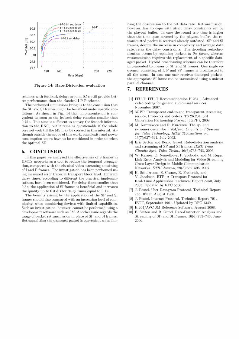
The graphs in Fig. 14 compares the rate distortion be-haviour of the proposed schemes, when optimizing the QPSP2as suggested in [10]. Major improvements are appreciatedwhen using the refined I-P-S scheme. The quality, thatpreviously saturated for increasing SD, is now increasingfor shorter distance between consecutive S frames. I-P-S
120 140 200 22029.6
29.8
30
30.2
30.4
30.6
30.8
Rate [kbps]
Y−PS
NR
[dB]
I-P-S 0.1 sec delayI-P-S 0.3 sec delayI-P-S 0.5 sec delay
I-P-S 1 sec delay
I-P-P
Figure 14: Rate-Distortion evaluation
schemes with feedback delays around 0.5 s still provide bet-ter performance than the classical I-P-P scheme.
The performed simulations bring us to the conclusion thatthe SP and SI frames might be beneficial under specific con-ditions. As shown in Fig. 14 their implementation is con-venient as soon as the feeback delay remains smaller than0.75 s. This time is sufficient to convey the feedack informa-tion to the RNC, but it remains questionable if the wholecore network till the MS may be crossed in this interval. Al-though outside the scope of this work, complexity and powerconsumption issues have to be considered in order to selectthe optimal SD.
6. CONCLUSIONIn this paper we analyzed the effectiveness of S frames in
UMTS networks as a tool to reduce the temporal propaga-tion, compared with the classical video streaming consistingof I and P frames. The investigation has been performed us-ing measured error traces at transport block level. Differentdelay times, according to different the practical implemen-tations, have been considered. For delay times smaller than0.5 s, the application of SI frames is beneficial and increasesthe quality up to 0.3 dB for delay times equal to 0.1 s.
The benefits arising by the application of the SP and SIframes should also compared with an increasing level of com-plexity, when considering devices with limited capabilities.Such an investigation, however, cannot be performed using adevelopment software such as JM. Another issue regards theusage of packet retransmission in place of SP and SI frames.Retransmitting the damaged packet is convenient when lim-
iting the observation to the net data rate. Retransmission,however, has to cope with strict delay constraints set bythe playout buffer. In case the round trip time is higherthan the time span covered by the playout buffer, the re-transmitted packet is received already outdated. SP and SIframes, despite the increase in complexity and average datarate, relax the delay constraints. The decoding resinchro-nization occurs by replacing packets in the future, whereasretransmission requires the replacement of a specific dam-aged packet. Hybrid broadcasting schemes can be thereforeimplemented by means of SP and SI frames. One single se-quence, consisting of I, P and SP frames is broadcasted toall the users. In case one user receives damaged packets,the appropriate SI frame can be transmitted using a unicastparallel channel.
7. REFERENCES
[1] ITU-T. ITU-T Recommendation H.264 : Advancedvideo coding for generic audiovisual services,November 2007.
[2] 3GPP. Transparent end-to-end transparent streamingservice; Protocols and codecs. TS 26.234, 3rdGeneration Partnership Project (3GPP), 2008.
[3] M. Karczewicz and R. Kurceren. The sp- andsi-frames design for h.264/avc. Circuits and Systemsfor Video Technology, IEEE Transactions on,13(7):637–644, July 2003.
[4] Eric Setton and Bernd Girod. Rate-distortion analysisand streaming of SP and SI frames. IEEE Trans.Circuits Syst. Video Techn., 16(6):733–743, 2006.
[5] W. Karner, O. Nemethova, P. Svoboda, and M. Rupp.Link Error Analysis and Modeling for Video StreamingCross-Layer Design in Mobile CommunicationNetworks. ETRI Journal, 29(5):569–595, 2007.
[6] H. Schulzrinne, S. Casner, R. Frederick, andV. Jacobson. RTP: A Transport Protocol forReal-Time Applications. Technical Report 3550, July2003. Updated by RFC 5506.
[7] J. Postel. User Datagram Protocol. Technical Report768, IETF, August 1980.
[8] J. Postel. Internet Protocol. Technical Report 791,IETF, September 1981. Updated by RFC 1349.
[9] H.264/AVC JM Reference Software, August 2008.
[10] E. Setton and B. Girod. Rate-Distortion Analysis andStreaming of SP and SI Frames. 16(6):733–743, June2006.


![MISB EG 0802 14 May 2009 H.264 / AVC Coding and ... · PDF fileEG 0802 H.264/AVC Coding and Multiplexing 3 4 Introduction The H.264/AVC video coding standard [1] is capable of delivering](https://img.pdfslide.us/doc/110x75/5aa9f36b7f8b9a81188d6502/misb-eg-0802-14-may-2009-h264-avc-coding-and-0802-h264avc-coding-and-multiplexing.jpg)