Embed Size (px)
Citation preview

Analysis of Verification System using SoC Platform
Communication Circuit & System Design Lab., Dept. of Computer and Communication Engineering,
Chungbuk National University, Korea

Contents Introduction
• What is SoC?• SoC Applications• Benefits of using SoC• Core technology• Today’s SoC design challenges
Platform based design methodology• What is platform for SoC?• Developing platform
Verification issues and our proposed verification flow Case study: IEEE 802.11a Verification result Conclusion Extra: SoC design in Mongolia

What is SoC?
CPU ROM
RAMASIC
System bus
System on Board System on Chip
CPURAM
ROMASIC
DSP
PLD
DSP
PLD

SoC Applications
Communication• Digital cellular phone
• Networking
Computer• PC/Workstation
• Chipsets
Consumer• Game box
• Digital Camera

Benefits of using SoC
Reduced size Reduced overall system cost Lower power consumption Increased performance

Core technology
High Speed&Low Power
Design
IP Development
SystemArchitecture
SoCVerification
EmbeddedSoftware
SoC design
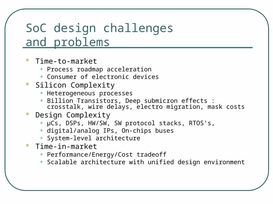
SoC design challenges and problems Time-to-market
• Process roadmap acceleration• Consumer of electronic devices
Silicon Complexity• Heterogeneous processes• Billion Transistors, Deep submicron effects : crosstalk, wire delays,
electro migration, mask costs Design Complexity
• µCs, DSPs, HW/SW, SW protocol stacks, RTOS’s,• digital/analog IPs, On-chips buses• System-level architecture
Time-in-market• Performance/Energy/Cost tradeoff• Scalable architecture with unified design environment

How to Conquer theComplexity?
Reuse a known real entity (Platform based design)• A pre-designed component (IP reuse)
• A platform (architecture reuse)
Partition• Based on functionality
• Hardware and software
Modeling• At different level
• Consistent and accurate

Platform based design methodology Hardware platform:
Basic micro-architecture consists of programmable cores, input-output (I/O) subsystems, buses and memories.
Software platform:Basic programmable cores and memory subsystem via a real-time operating system (RTOS), I/O subsystems via the Device Drivers and network connection via network communication subsystem.
Application platform interface (API)Interface between HW/SW platforms
System platformHW/SW platforms and API are system platform.

Effects of platform based design methodology in SoC design
Complexity is drastically decreased SoC platform intend to become fully
programmable cores Designer prefers SW design way than
HW design

Effects of platform based design methodology in SoC design But 60 % to 80 % of design effort is now dedicated for verification task
Code
Code
Verify (40~60%) Synthesis P/R
Verify (60~80%) Synthesis P/R
2000300K gates
1M gates
2004

Verification issues In order to resolve the verification bottleneck, researchers
use several verification methods• Informal (design review, code inspection …)• Dynamic (simulation based, prototyping, emulation …)• Static (formal, model checker …)

Emulation based co-verification flow vs. conventional flow
A. Conventional verification flow B. Emulation based co-verification flow

Emulation based verification system In general, HW design accelerated on FPGA, SW design accelerated on
processor models. So emulation based verification system is significantly affected from processor model. There are three basic model of processor:
Speed Debugging Accuracy Cost
ISSmodel
Low HighDepend onmodel
Low
RTLmodel
Low High High Low
PhysicalModel
High Low Very high High

Verification models
We assume: case “a” is the best case for HW, case “b” is the best case for SW case “c” is the best case for system design
verification of functionality.

Case study: IEEE 802.11a
IEEE 802.11 family 802.11b: physical layer uses Direct Sequence Spread Spectrum (DSSS) or
Frequency Hopping (FH), operates at 2.4GHz, 11Mbps bit rate
802.11a: uses orthogonal frequency-division multiplexing between 5GHz and 6GHz, up to 54Mbps bit rate
802.11g: operates at 2.4GHz up to 54Mbps bit rate
Those protocols specify MAC and PHY layers of wireless network model.
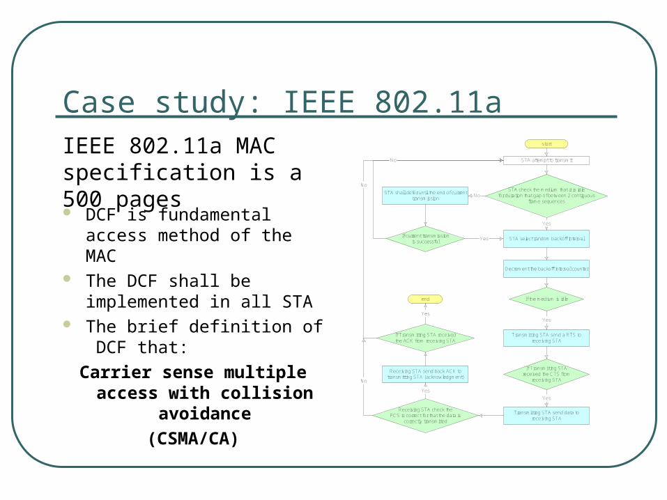
Case study: IEEE 802.11a
DCF is fundamental access method of the MAC
The DCF shall be implemented in all STA
The brief definition of DCF that:
Carrier sense multiple access with collision
avoidance
(CSMA/CA)
IEEE 802.11a MAC specification is a 500 pages
start
STA attempt to transmit
STA check the medium that it is idlefor duration that gap of between 2 contiguous
frame sequences
STA shall defer until the end of currenttransmission
STA select random backoff interval
Decrement the backoff interval counter
If the medium is idle
Transmitting STA send a RTS toreceiving STA
If Transmitting STAreceived the CTS from
receiving STA
Transmitting STA send data toreceiving STA
end
If current transmissionis successful
If Transmitting STA receivedthe ACK from receiving STA
Receiving STA check theFCS is correct for that the data is
correctly transmitted
Receiving STA send back ACK totransmitting STA (acknowledgment)
No
Yes
Yes
Yes
Yes
Yes
Yes
No
No
No
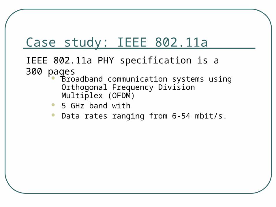
Case study: IEEE 802.11a
Broadband communication systems using Orthogonal Frequency Division Multiplex (OFDM)
5 GHz band with Data rates ranging from 6-54 mbit/s.
IEEE 802.11a PHY specification is a 300 pages
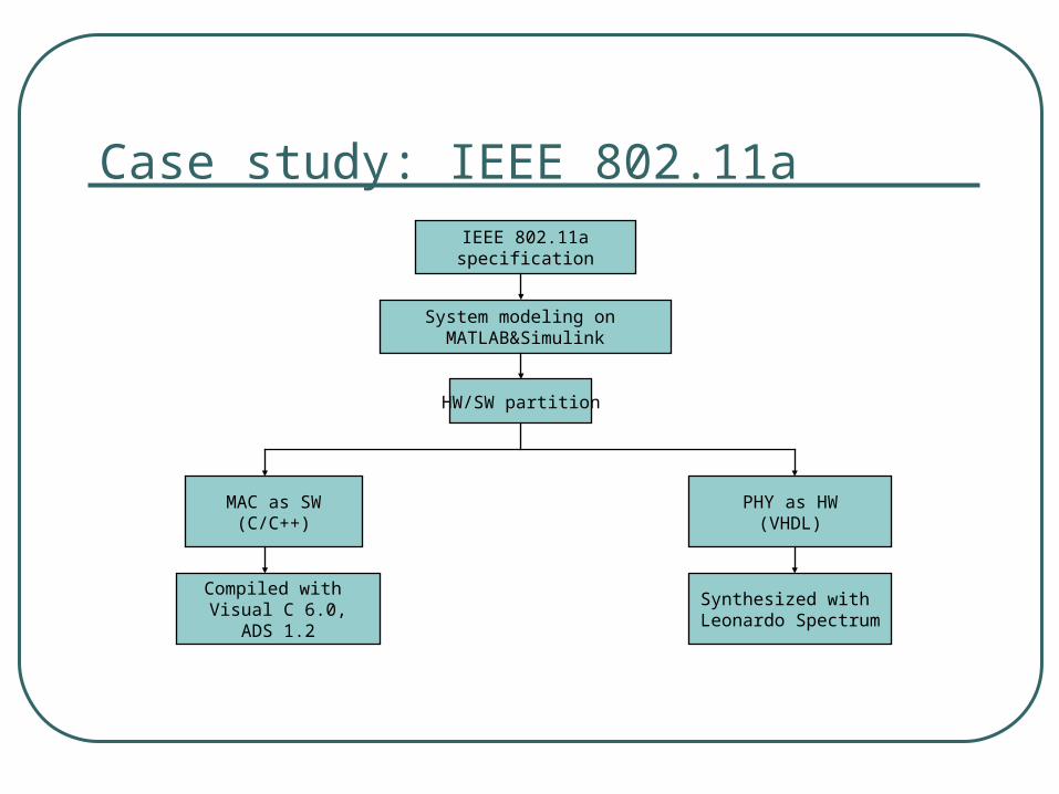
Case study: IEEE 802.11aIEEE 802.11aspecification
System modeling on MATLAB&Simulink
HW/SW partition
MAC as SW(C/C++)
PHY as HW(VHDL)
Compiled with Visual C 6.0,
ADS 1.2
Synthesized with Leonardo Spectrum
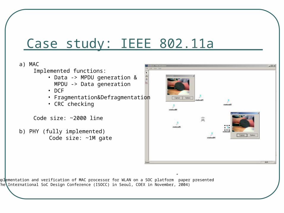
Case study: IEEE 802.11aa) MAC
Implemented functions:• Data -> MPDU generation & MPDU -> Data generation • DCF• Fragmentation&Defragmentation• CRC checking
Code size: ~2000 line
b) PHY (fully implemented) Code size: ~1M gate
(“Implementation and verification of MAC processor for WLAN on a SOC platform” paper presented on The International SoC Design Conference (ISOCC) in Seoul, COEX in November, 2004)

Emulation system platform
Multi-ICEMulti-ICE ARMCore
Module
ARMCore
Module
ARMBaseBoard
ARMBaseBoard
DPPDPP
iPROVE (FPGA card)iPROVE (FPGA card)
HOST PC
1. Matlab&Simulink2. ISS (Armulator)3. Modelsim
HOST PC
1. Matlab&Simulink2. ISS (Armulator)3. Modelsim
JTAGJTAG
RS232RS232
PCIPCI
MACMAC
5/23
PHYPHY

Emulation system models
5/23
a. Pure C/C++
b. ISS
c. Pure engine

Verification result
5/23
1x
474x
2630x
55165000x
462963x
1904722x
Gate level RTL level TLM (Cycle mode) TLM (Transactionmode)
System level (ISS) System (ARMboard)
Speedup : log(speedup)

Verification result
5/23
0% 10% 20% 30% 40% 50% 60% 70% 80% 90% 100%
Pure C model
ISS model
Physical engine
Communication interface Embedded software Custom hardware

Conclusion
Advantages:• Co-verification is successfully performed in
few weeks
• Very high verification performance
• Communication interface is significantly affect whole performance

Conclusion
Performance Cost
Pure CAD tools Very low Low
SW design CAD tools,HW accelerator
High High
SW design on physical model, HW design on CAD
Low (depend on HW design size) Medium
Pure physical modelVery high (depend oncommunication interface)
Veryhigh

Referencehttp://www.dynalith.com/2003/document/SuccessStory_IEEE802.11a_CBU.pdf

Extra: SoC design in Mongolia
SoC дизайн
Үйлдвэрлэл&автоматжуулалт
Их сургууль&эрдэм
шинжилгээний институт