Embed Size (px)
Citation preview
NOVATEUR PUBLICATIONS
INTERNATIONAL JOURNAL OF INNOVATIONS IN ENGINEERING RESEARCH AND TECHNOLOGY [IJIERT]
ISSN: 2394-3696 VOLUME 2, ISSUE 11, Nov.-2015
1 | P a g e
ANALYSIS OF TUNED FILTERS FOR MITIGATION OF
HARMONIC CURRENT DISTORTION OF RESIDENTIAL
LOAD
Yogesh Bhujbal
M.E. Scholar Department of Electrical G.H.I.E.R.T,
S.F. Pune University, Pune
Prof. P.N. Korde
Head of Electrical Department G.H.I.E.R.T,
S.F. Pune University, Pune
ABSTRACT
Harmonics are the by-products of modern electronic devices that are nonlinear loads which
create harmonics by drawing current in rather than smooth sinusoidal manner. Any
distribution circuit feeding nonlinear loads will contain some degree of harmonic frequencies.
Due to the rapidly increasing number of non-linear loads in distribution systems, the
harmonic distortion of the current and voltage increases. Non-linear loads are personal
computer, television set (TV), fluorescent tube with electronic ballast, compact fluorescent
lamp, battery charger, uninterrupted power supply (UPS) and any other equipment powered
by switched-mode power supply (SMPS) unit. The harmonic distortion produced in
residential buildings has not been given proper attention as linear loads were predominant
earlier. As the number of harmonics-producing loads in residences has increased over the
years, it has become increasingly necessary to address their effects on the distribution system.
Power Quality of distribution networks is affected due to the flow of generated harmonics.
Harmonic currents generated by nonlinear loads can cause problems on equipments of
distribution network. These harmonics can cause excessive heat in many appliances, and
hence reduce the life span of the distribution transformer supplying such loads. It can also
increase power consumption and reduce system efficiency. It also lowers the power factor,
resulting in penalties to consumers. In this paper presents the results of a SIMULINK of
harmonic distortion caused by non linear home appliances on bus bar and then it
compensated by filter. The scope of work includes analysis of percentage of total harmonic
distortions before and after compensation and found reduced percentage of THD after the
compensation. Percentage of distortions are compensated using 3rd
and 5th
harmonic filter
and these filters are directly connected to the 0.4kv feeder (PCC) from which three phases are
split with neutral to home appliances.
Keywords: %THD, Non linear load, Matlab-Simulink, TDD, FFT tool, PCC, Filter, Power
quality.

NOVATEUR PUBLICATIONS
INTERNATIONAL JOURNAL OF INNOVATIONS IN ENGINEERING RESEARCH AND TECHNOLOGY [IJIERT]
ISSN: 2394-3696 VOLUME 2, ISSUE 11, Nov.-2015
2 | P a g e
INTRODUCTION
Electric utilities are concerned about decreasing power quality and its potential impacts on
the grid. As residential customers add more electronics to the home and replace existing
mechanical switching equipments by electronic switching equipments, there is a concern that
local grid stability could be compromised. In an effort to determine how residential power
quality (as measured by power factor and total harmonic distortion) is changing over time,
Advanced Energy proposed to survey the current research on residential power quality and
measure actual power quality for two residential homes of different ages under different load
conditions[6][1]. Harmonic distortion is the distortion of either the voltage or current
waveform with the addition of frequencies other than the fundamental 50 Hertz frequency.
Harmonics are generated by non-linear loads such as computers, battery charging systems,
variable frequency drives and other electronic equipment. Total harmonic distortion indicates
the combined impact of all harmonics upon the fundamental waveform. Since utilities
provide a 50 Hertz voltage source of electricity, the voltage waveform supplied is fairly
constant. Various loads on the grid can, however, impact the current waveform. The primary
concern in residential locations are the third harmonic and other triplens (3rd
, 9th
, 15th
, etc.)
harmonics. Each harmonic exists at a multiple of the fundamental frequency. Many of these
harmonics can cancel each other out. Triplen harmonics, however, are additive and will
combine with each other, as well as the fundamental frequency, to have more deteriorating
impacts.
BLOCK RESIDENIAL LOAD
In block diagram shows that incoming three phase supply are connected to PCC. Capacity of
PCC is 0.4 KV. Three phase manual circuit breaker connected between loads and PCC. In
between PCC and manual circuit breaker 3rd
and 5th
harmonic filter are connected. Purpose of
this filter is that from analysis 3rd
and 5th
harmonics current harmonics magnitude are more in
residential load [10]. Single phases 230v carried out from PCC by neutral. On each phase
various modern home appliances are connect and analyze the emission of harmonics from it.
Figure 1: Block Diagram Residential load Harmonic Analysis
NOVATEUR PUBLICATIONS
INTERNATIONAL JOURNAL OF INNOVATIONS IN ENGINEERING RESEARCH AND TECHNOLOGY [IJIERT]
ISSN: 2394-3696 VOLUME 2, ISSUE 11, Nov.-2015
3 | P a g e
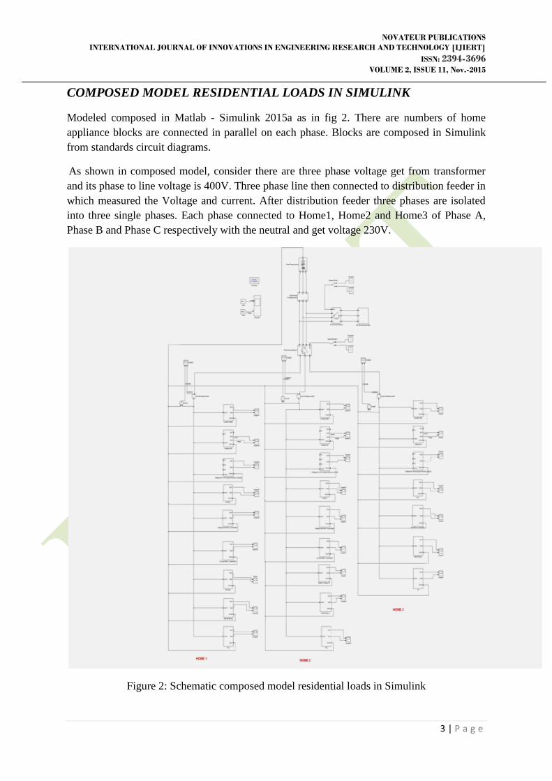
COMPOSED MODEL RESIDENTIAL LOADS IN SIMULINK
Modeled composed in Matlab - Simulink 2015a as in fig 2. There are numbers of home
appliance blocks are connected in parallel on each phase. Blocks are composed in Simulink
from standards circuit diagrams.
As shown in composed model, consider there are three phase voltage get from transformer
and its phase to line voltage is 400V. Three phase line then connected to distribution feeder in
which measured the Voltage and current. After distribution feeder three phases are isolated
into three single phases. Each phase connected to Home1, Home2 and Home3 of Phase A,
Phase B and Phase C respectively with the neutral and get voltage 230V.
Figure 2: Schematic composed model residential loads in Simulink
NOVATEUR PUBLICATIONS
INTERNATIONAL JOURNAL OF INNOVATIONS IN ENGINEERING RESEARCH AND TECHNOLOGY [IJIERT]
ISSN: 2394-3696 VOLUME 2, ISSUE 11, Nov.-2015
4 | P a g e
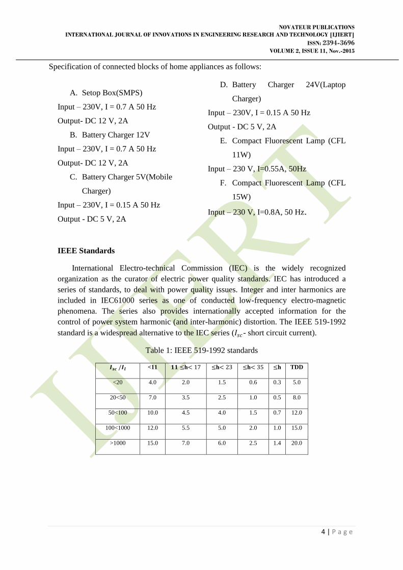
Specification of connected blocks of home appliances as follows:
A. Setop Box(SMPS)
Input – 230V, I = 0.7 A 50 Hz
Output- DC 12 V, 2A
B. Battery Charger 12V
Input – 230V, I = 0.7 A 50 Hz
Output- DC 12 V, 2A
C. Battery Charger 5V(Mobile
Charger)
Input – 230V, I = 0.15 A 50 Hz
Output - DC 5 V, 2A
D. Battery Charger 24V(Laptop
Charger)
Input – 230V, I = 0.15 A 50 Hz
Output - DC 5 V, 2A
E. Compact Fluorescent Lamp (CFL
11W)
Input – 230 V, I=0.55A, 50Hz
F. Compact Fluorescent Lamp (CFL
15W)
Input – 230 V, I=0.8A, 50 Hz.
IEEE Standards
International Electro-technical Commission (IEC) is the widely recognized
organization as the curator of electric power quality standards. IEC has introduced a
series of standards, to deal with power quality issues. Integer and inter harmonics are
included in IEC61000 series as one of conducted low-frequency electro-magnetic
phenomena. The series also provides internationally accepted information for the
control of power system harmonic (and inter-harmonic) distortion. The IEEE 519-1992
standard is a widespread alternative to the IEC series (𝐼𝑠𝑐- short circuit current).
Table 1: IEEE 519-1992 standards
𝑰𝒔𝒄 /𝑰𝒍 <11 𝟏𝟏 ≤h< 17 ≤h< 23 ≤h< 35 ≤h TDD
<20 4.0 2.0 1.5 0.6 0.3 5.0
20<50 7.0 3.5 2.5 1.0 0.5 8.0
50<100 10.0 4.5 4.0 1.5 0.7 12.0
100<1000 12.0 5.5 5.0 2.0 1.0 15.0
>1000 15.0 7.0 6.0 2.5 1.4 20.0
NOVATEUR PUBLICATIONS
INTERNATIONAL JOURNAL OF INNOVATIONS IN ENGINEERING RESEARCH AND TECHNOLOGY
[IJIERT]
ISSN: 2394-3696 VOLUME 2, ISSUE 11, Nov.-2015
5 | P a g e
Total harmonic distortion (THD) Calculation
𝑇𝐻𝐷𝐼 =1
𝑖1 𝑖𝑟𝑚𝑠2 − 𝑖1
2 × 100% (1)
𝑇𝐻𝐷𝑉 =1
𝑣1 𝑣𝑟𝑚𝑠2 − 𝑣1
2 × 100% (2)
𝑇𝐻𝐷𝑇𝑜𝑡𝑎𝑙 = 𝑇𝐻𝐷21 + 𝑇𝐻𝐷2
2 + 𝑇𝐻𝐷20
× 100% (3)
FILTERS
Assuming negligible resistive part, the angular frequency series resonance circuit can be
determined by the equation (4)
𝑊0 =1
𝐿𝐶= 2𝜋𝑓0 =
2𝜋
𝑇0 (4)
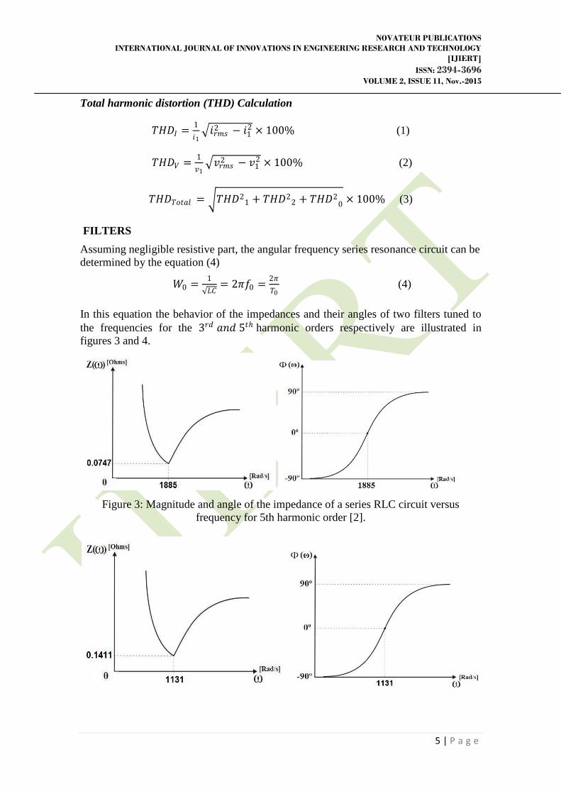
In this equation the behavior of the impedances and their angles of two filters tuned to
the frequencies for the 3𝑟𝑑 𝑎𝑛𝑑 5𝑡ℎ harmonic orders respectively are illustrated in
figures 3 and 4.
Figure 3: Magnitude and angle of the impedance of a series RLC circuit versus
frequency for 5th harmonic order [2].
NOVATEUR PUBLICATIONS
INTERNATIONAL JOURNAL OF INNOVATIONS IN ENGINEERING RESEARCH AND TECHNOLOGY
[IJIERT]
ISSN: 2394-3696 VOLUME 2, ISSUE 11, Nov.-2015
6 | P a g e
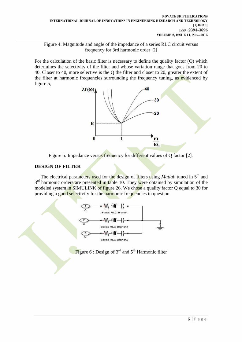
Figure 4: Magnitude and angle of the impedance of a series RLC circuit versus
frequency for 3rd harmonic order [2]
For the calculation of the basic filter is necessary to define the quality factor (Q) which
determines the selectivity of the filter and whose variation range that goes from 20 to
40. Closer to 40, more selective is the Q the filter and closer to 20, greater the extent of
the filter at harmonic frequencies surrounding the frequency tuning, as evidenced by
figure 5,
Figure 5: Impedance versus frequency for different values of Q factor [2].
DESIGN OF FILTER
The electrical parameters used for the design of filters using Matlab tuned in 5th
and
3rd
harmonic orders are presented in table 10. They were obtained by simulation of the
modeled system in SIMULINK of figure 26. We chose a quality factor Q equal to 30 for
providing a good selectivity for the harmonic frequencies in question.
Figure 6 : Design of 3
rd and 5
th Harmonic filter
NOVATEUR PUBLICATIONS
INTERNATIONAL JOURNAL OF INNOVATIONS IN ENGINEERING RESEARCH AND TECHNOLOGY
[IJIERT]
ISSN: 2394-3696 VOLUME 2, ISSUE 11, Nov.-2015
7 | P a g e
Table 2 3rd
and 5th
Harmonic Filter parameters
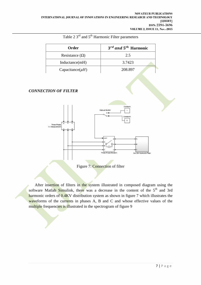
CONNECTION OF FILTER
Figure 7: Connection of filter
After insertion of filters in the system illustrated in composed diagram using the
software Matlab Simulink, there was a decrease in the content of the 5th
and 3rd
harmonic orders of 0.4KV distribution system as shown in figure 7 which illustrates the
waveforms of the currents in phases A, B and C and whose effective values of the
multiple frequencies is illustrated in the spectrogram of figure 9
Order 𝟑𝒓𝒅 𝒂𝒏𝒅 𝟓𝒕𝒉 Harmonic
Resistance (Ω) 2.5
Inductance(mH) 3.7423
Capacitance(𝜇𝐻) 208.897
NOVATEUR PUBLICATIONS
INTERNATIONAL JOURNAL OF INNOVATIONS IN ENGINEERING RESEARCH AND TECHNOLOGY
[IJIERT]
ISSN: 2394-3696 VOLUME 2, ISSUE 11, Nov.-2015
8 | P a g e
Table 3 Comparative of total current harmonic distortions (a) before (b) after the
presence of tuned filters of 5th and 3rd harmonic orders (THD %).
(a)
(b)
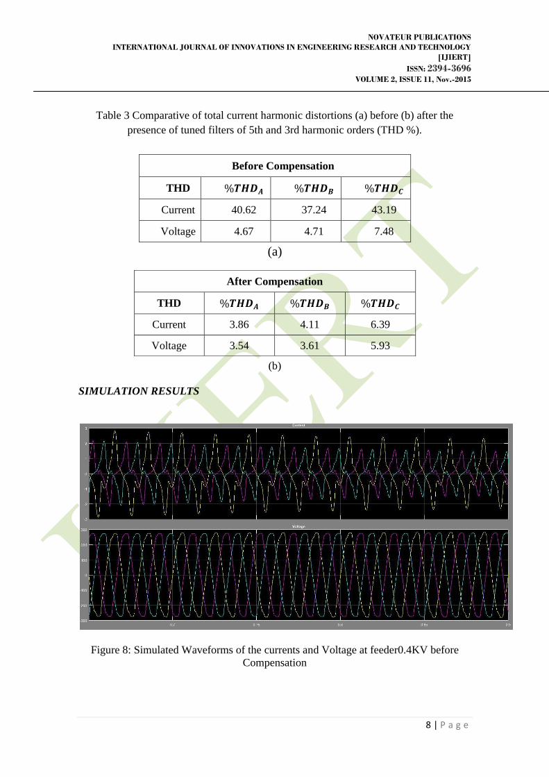
SIMULATION RESULTS
Figure 8: Simulated Waveforms of the currents and Voltage at feeder0.4KV before
Compensation
Before Compensation
THD %𝑻𝑯𝑫𝑨 %𝑻𝑯𝑫𝑩 %𝑻𝑯𝑫𝑪
Current 40.62 37.24 43.19
Voltage 4.67 4.71 7.48
After Compensation
THD %𝑻𝑯𝑫𝑨 %𝑻𝑯𝑫𝑩 %𝑻𝑯𝑫𝑪
Current 3.86 4.11 6.39
Voltage 3.54 3.61 5.93
NOVATEUR PUBLICATIONS
INTERNATIONAL JOURNAL OF INNOVATIONS IN ENGINEERING RESEARCH AND TECHNOLOGY
[IJIERT]
ISSN: 2394-3696 VOLUME 2, ISSUE 11, Nov.-2015
9 | P a g e
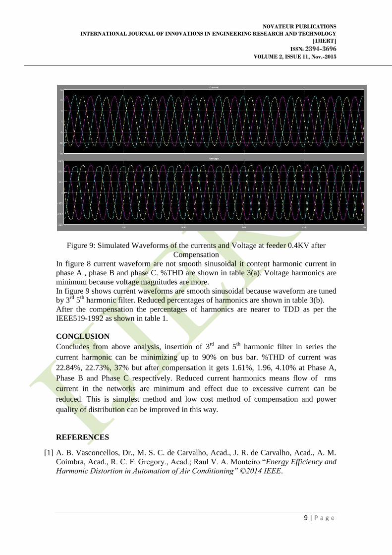
Figure 9: Simulated Waveforms of the currents and Voltage at feeder 0.4KV after
Compensation
In figure 8 current waveform are not smooth sinusoidal it content harmonic current in
phase A , phase B and phase C. %THD are shown in table 3(a). Voltage harmonics are
minimum because voltage magnitudes are more.
In figure 9 shows current waveforms are smooth sinusoidal because waveform are tuned
by 3rd
5th
harmonic filter. Reduced percentages of harmonics are shown in table 3(b).
After the compensation the percentages of harmonics are nearer to TDD as per the
IEEE519-1992 as shown in table 1.
CONCLUSION
Concludes from above analysis, insertion of 3rd
and 5th
harmonic filter in series the
current harmonic can be minimizing up to 90% on bus bar. %THD of current was
22.84%, 22.73%, 37% but after compensation it gets 1.61%, 1.96, 4.10% at Phase A,
Phase B and Phase C respectively. Reduced current harmonics means flow of rms
current in the networks are minimum and effect due to excessive current can be
reduced. This is simplest method and low cost method of compensation and power
quality of distribution can be improved in this way.
REFERENCES
[1] A. B. Vasconcellos, Dr., M. S. C. de Carvalho, Acad., J. R. de Carvalho, Acad., A. M.
Coimbra, Acad., R. C. F. Gregory., Acad.; Raul V. A. Monteiro “Energy Efficiency and
Harmonic Distortion in Automation of Air Conditioning” ©2014 IEEE.
NOVATEUR PUBLICATIONS
INTERNATIONAL JOURNAL OF INNOVATIONS IN ENGINEERING RESEARCH AND TECHNOLOGY
[IJIERT]
ISSN: 2394-3696 VOLUME 2, ISSUE 11, Nov.-2015
10 | P a g e
[2] Arnulfo B. de Vasconcellos, Dr., Marina S. C. de Carvalho, Acad., Andrei M. Coimbra,
Acad., Jéssica R. de Carvalho, Acad., Raul V. A. Monteiro, Esp. “Analysis of Tuned
Filters for Mitigation of Harmonic Current Distortion of Air Conditioning Systems to
Inverter” 2014 IEEE
[3] J. Niitsoo, I. Palu, J. Kilter, P. Taklaja, T. Vaimann. “Residential Load Harmonics in
Distribution Grid” 3rd International Conference on Electric Power and Energy
Conversion Systems, Yildiz Technical University, Istanbul, Turkey, October 2-4, 2013
IEEE.
[4] MOK Yan, Kit, TSE C.F. Norman, LAU W.H. “A Study on the Effects of Voltage
Distortion on Current Harmonics Generated By Modern SMPS Driven Home
Appliances in Smart Grid Network” IEEE2012.
[5] Agus Purwadi, Nana Heryana, Dadan Nurafiat “ A Study of Harmonic Impacts on High
Voltage, Medium Voltage and Low Voltage Networks in PT. PLN Distribution System” ,
Indonesia ©2011 IEEE.
[6] Khodijah Mohamed,Hussain Shareef, Azah Mohamed Malaysia. “Analysis of Harmonic
Emission from Dimmable Compact Fluorescent Lamps” International Conference on
Electrical Engineering and Informatics 17-19 July 2011, Bandung, Indonesia ©2011
IEEE.
[7] Ranjana Singh, Amarjit Singh “Energy Loss Due to Harmonics in Residential Campus
– A Case Study. UPEC2010 31st Aug - 3rd Sept IEEE 2010.
[8] Jing Yong, Member, IEEE, Liang Chen, and Shuangyan Chen “Modeling of Home
Appliances for Power Distribution System Harmonic Analysis” IEEE Transactions On
Power Delivery, OCTOBER 2010.
[9] V. KatiC*, B. DumniC*, S. Mujovic", J.RadoviC*** “Effects of Low Power Electronics
& Computer Equipment Forecast”. International Conference on Industrial Technology
(ICIT), 2004 IEEE.
[10] Yogesh Bhujbal, Prof. Ravindra Joshi, Amol Chate “Analysis and Simulation Of
Harmonics For Various Residential Loads Using Simulink” [IJIERT] ISSN: 2394-3696
VOLUME 2, ISSUE 8, AUG-2015.


![Microwave Microstrip Tunable Bandpass Filters – technology ... planar... · Equivalent circuits of the varactor tuned combline ... [35], the noise figure of the active filter is](https://img.pdfslide.us/doc/110x75/5b4f6ebd7f8b9a256e8c4ede/microwave-microstrip-tunable-bandpass-filters-technology-planar-equivalent.jpg)