Embed Size (px)
Citation preview
“Analysis Of Thermoflow Characteristics Of Offset Strip Fins With Different
Working Fluids”
Ruchi Shukla* Jitendra Kumar Tiwari** Harbans Singh Ber***
SSCET Bhilai C.G. Sr.Associate prof. Asst Prof.
SSCET Bhilai C.G. KITE,Raipur C.G.
Abstract
The paper emphasizes on the analysis of thermo flow characteristics for the offset strip fin. This
is the most widely used fin geometry in high performance plate fin heat exchangers. The
correlations suggested in this work by the researcher for the j values in the turbulent and
transition regions estimated the values of j which are close to the values suggested by Manglik
and Bergles. The correlations for j and f values are presented. The modified correlations which
can be applied for working fluid other than air are also presented. The correlations presented are
based on Prandtl number. The working fluids used for analysis are air, mercury, noble gas and R-
12.The graphical results are incorporated in the work for different blockage ratio up to 35%. The
effect on colburn factor for different fluids with respect to Reynolds number is analyzed in the
work. The probable cause for variation in the Colburn factor, j with change in working fluid is
also investigated. And as the Colburn factor bears a directly proportional relationship to the
convective heat transfer coefficient and also bears a an inversely proportional relationship to the
product of thermal conductivity and density, these parameters being different for different fluids
cause a change in the heat transfer characteristics of the fluids. The results obtained
experimentally are found in agreement to the effect of the various parameters. Further future
scope is also manifested at the end of the work.
LIST OF NOMENCLATURE
A Area (m2)
cp Specific heat at constant pressure (J/kg-K)
Dh Hydraulic dia. (mm)
f Friction factor, 2∆𝑝
𝜌𝑢𝑐2
𝐷ℎ
4𝐿
h Height of offset strip fin (mm)/heat transfer coefficient (W/m2-K)
j Colburn factor, 𝑁𝑢
𝜌𝑢𝑐2
𝐷ℎ
4𝐿
JF JF factor, [(j/jref) / (f/fref)]1/3
International Journal of Engineering Research & Technology (IJERT)
Vol. 2 Issue 3, March - 2013ISSN: 2278-0181
1www.ijert.org
IJERT
IJERT

k Thermal conductivity (W/m-K)/ turbulent Kinetic energy (m2/s
2)
l Length of the offset strip fin(mm)
𝑚 mass flow rate (kg/s)
Nu Nusselt no., ℎ 𝐷ℎ
𝑘
n Normal direction
Pr Prandtl no., 𝜇𝑐𝑝
𝑘
p Pressure (Pa)
∆𝑝 Pressure drop (Pa)
𝑄 Heat transfer rate (W)
Re Reynolds number 𝜌𝑢𝑐𝐷ℎ
𝜇
𝑆𝛷 Source term of Φ
s Spacing of the offset strip fin (mm)
T Temperature (°𝐶)
t Thickness of the offset strip fin (mm)
u,v,w Velocity (m/s)
Greek symbols
α s/h
β Blockage ratio
γ t/s
δ t/l
Γ𝜙 Diffusivity variable
δij Kronecker delta
휀 Dissipation rate of turbulent kinetic energy (m2/s
3)
ρ density(kg/m3)
ϕ general dependent variable
µ Dynamic viscosity (kg/ms)
International Journal of Engineering Research & Technology (IJERT)
Vol. 2 Issue 3, March - 2013ISSN: 2278-0181
2www.ijert.org
IJERT
IJERT
ω specification dissipation rate (s-1
)
Subscripts
eff effective
in inlet
opt optimum
out outlet
ref reference
t turbulence
total total
vac vacancy
wall wall
1. Introduction
Extended surfaces have wide industrial application as fins attached to the walls of heat transfer
equipments in order to increase the rate of heat transfer i.e. heating or cooling. Fins are of many
shapes & forms. In the study of heat transfer, a fin is a surface that extends from an object to
increase the rate of heat transfer to or from the environment by increasing convection. The
amount of conduction, convection, or radiation of an object determines the amount of heat it
transfers. Increasing the temperature difference between the object and the environment,
increasing the convection heat transfer coefficient or increasing the surface area of the object
increases the heat transfer. Sometimes, it is not economical or it is not feasible to change the first
two options. Adding a fin to an object, however, increases the surface area and can sometimes be
an economical solution to the heat transfer problems.
Offset-strip fins are widely used for plate-fin heat exchangers to enhance heat transfer rate by
enlarging surface area and regenerating thermal boundary layer in each column. However, offset-
strip fins induce a large pressure drop between the inlet and outlet of a plate-fin heat exchanger.
Therefore, the heat transfer and pressure drop in offset-strip fins need to be investigated.
Furthermore, the offset-strip fin must be optimally designed so that it can reconcile these
contradictory phenomena. Offset-strip fin heat exchangers have been in use for decades. This
type of compact heat exchanger takes advantage of boundary layer restarting to enhance heat
transfer over that of plain-fin heat exchangers. Since the average boundary-layer thickness
decreases significantly when offset-strip fins are used, the convection coefficient increases. At
moderate Reynolds numbers (Re > 700), vortex shedding can occur in the array, causing further
heat transfer enhancement. Both of these enhancement mechanisms also increase pressure drop
across the array. Heat transfer is typically proportional to the flow velocity, but the power
required to move the flow (pumping power, or fan power) is proportional to the velocity cubed;
International Journal of Engineering Research & Technology (IJERT)
Vol. 2 Issue 3, March - 2013ISSN: 2278-0181
3www.ijert.org
IJERT
IJERT
therefore, offset-strip fin heat exchangers are usually operated at Reynolds numbers much below
1,000 in order to manage heat-duty-pumping-power design tradeoffs.
At these low Reynolds numbers, the air-side flow is steady and laminar. The thermal-hydraulic
performance of offset-set strip fin heat exchangers has been studied extensively for flows in this
regime.
2. Literature review
Researchers have studied about offset strip fins [1–10]. Largely these studies involved air as the
working fluid, few fin geometries are applicable to practical offset-strip fins with working fluids
other than air. Kays and London [1] were the first to explore a correlation for offset-strip fins
based on experimental results. Manson [2] performed experiments with fin geometries. Wieting
[3] obtained a correlation using 22 fin geometries. Mochizuki et al. [4] presented more accurate
correlations by modifying those of Wieting [3]. Joshi and Webb [5] suggested correlations in
both laminar and turbulent regimes. Manglik and Bergles [6] presented a correlation that could
be applied to the laminar, transition, and turbulent regimes by using experimental data from the
literature. Because the working fluid was air, however, their correlations cannot be used for other
working fluids whose Prandtl numbers are higher than that of air. For this reason, some studies
[7–10] have considered working fluids other than air. For instance, Tinaut et al. [7] experimented
with offset strip fin heat exchangers that used water and engine oil. Hu and Herold [8]
investigated heat transfer and pressure drop in offset strip fins with water and polyalphaolefin as
the working fluids. Muzychka [9] and Muzychka and Yovanovich [10] performed experiments
using transmission oil as the working fluid and derived correlations by an analytical model. The
number of fin geometries they tested, however, was not sufficiently large to establish a general
correlation. The optimal design of a thermal fluid system, such as an offset strip fin heat
exchanger, generally uses a function-based approximation method instead of a gradient-based
approximation method [11] because of the latter’s excessive computational time and the
nonlinearity of the function [12]. The response surface method [13–16] utilizes a function-based
approximation and is a global optimization method applicable to many design fields. The
response surface method accurately describes the trend of the design solution. However, this
method cannot accurately present the local value when the variation of the objective function
according to the design variables is very large. M.S Kim, Jonghyeok Lee, Se-Jin Yook, Kwan-
Soo Lee presented correlations based on prandtl number for blockage ratio up to 35%.
3. Theoretical analysis
3.1 Governing equations
In the present model, it is assumed that:
(1) The flow is three-dimensional and incompressible.
(2) The working fluids are in a single phase, and their properties remain constant.
(3) Natural convection and thermal radiation can be neglected.
Depending on the Reynolds number, the flow across an offset strip fin is categorized as laminar,
transition, or turbulent. Since oscillatory flow exists in the transition and turbulent regimes.
International Journal of Engineering Research & Technology (IJERT)
Vol. 2 Issue 3, March - 2013ISSN: 2278-0181
4www.ijert.org
IJERT
IJERT
The governing equation is as follows: 𝝏
𝝏𝒕 𝝆∅ +
𝝏
𝝏𝒙𝒊
𝝆𝒖𝒊∅ = 𝝏
𝝏𝒙𝒊 𝜞∅
𝝏∅
𝝏𝒙𝒊 + 𝑺∅. (𝟏)
Interfacial boundary conditions
At the interface between the fluid and solid, the boundary conditions were:
𝒖𝒘𝒂𝒍𝒍 = 𝒗𝒘𝒂𝒍𝒍 = 𝒘𝒘𝒂𝒍𝒍 = 𝟎,𝒂𝒏𝒅 𝑻 = 𝑻𝑺. (𝟐)
Inlet and outlet conditions
The inlet and outlet conditions were described by:
𝒎 = 𝒎 𝒊𝒏, 𝑻𝒇 = 𝑻𝒊𝒏, 𝑰𝒊𝒏 = 𝟎.𝟏𝟔𝑹𝒆𝑫𝒉
−𝟏𝟖, 𝟑
𝒎 = 𝒎 𝒐𝒖𝒕 = 𝒎 𝒊𝒏 , 𝝏𝒌
𝝏𝒏= 𝟎,
𝝏𝝎
𝝏𝒏= 𝟎,
𝝏𝝆
𝝏𝒏= 𝟎,
𝝏𝑻
𝝏𝒏= 𝟎. (𝟒)
Following Manglik and Bergles [6], the hydraulic diameter was defined as:
𝑫𝒉 =𝟒𝒔𝒉𝒍
𝟐 𝒔𝒍 + 𝒉𝒍 + 𝒕𝒉 + 𝒕𝒔 . (𝟓)
The blockage ratio is defined as:
𝜷 =𝑨𝒕𝒐𝒕𝒂𝒍 − 𝑨𝒗𝒂𝒄
𝑨𝒕𝒐𝒕𝒂𝒍=
𝟐𝒔 + 𝟐𝒕 𝒉 + 𝒕 − 𝟐𝒔𝒉
𝟐𝒔 + 𝟐𝒕 𝒉 + 𝒕 , (𝟔)
= 𝟏 −𝟏
𝟏 + 𝜶𝜸 + 𝜸 + 𝜶𝜸𝟐 × 𝟏𝟎𝟎%. (𝟕)
International Journal of Engineering Research & Technology (IJERT)
Vol. 2 Issue 3, March - 2013ISSN: 2278-0181
5www.ijert.org
IJERT
IJERT
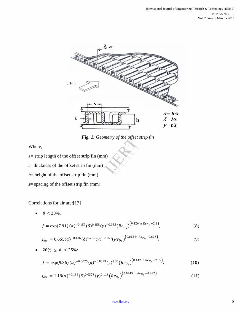
Fig. 1: Geometry of the offset strip fin
Where,
l = strip length of the offset strip fin (mm)
t= thickness of the offset strip fin (mm)
h= height of the offset strip fin (mm)
s= spacing of the offset strip fin (mm)
Correlations for air are:[17]
𝛽 < 20%:
𝑓 = exp 7.91 𝛼 −0.159 𝛿 0.358 𝛾 −0.033 𝑅𝑒𝐷ℎ 0.126 ln 𝑅𝑒𝐷ℎ
−2.3 , (8)
𝑗𝑎𝑖𝑟 = 0.655 𝛼 −0.136 𝛿 0.236 𝛾 −0.158 𝑅𝑒𝐷ℎ 0.015 ln 𝑅𝑒𝐷ℎ
−0.623 . (9)
20% ≤ 𝛽 < 25%:
𝑓 = exp 9.36 𝛼 −0.0025 𝛿 −0.0373 𝛾 1.85 𝑅𝑒𝐷ℎ 0.142 ln 𝑅𝑒𝐷ℎ
−2.39 , (10)
𝑗𝑎𝑖𝑟 = 1.18 𝛼 −0.134 𝛿 0.0373 𝛾 0.118 𝑅𝑒𝐷ℎ 0.0445 ln 𝑅𝑒𝐷ℎ
−0.982 . (11)
International Journal of Engineering Research & Technology (IJERT)
Vol. 2 Issue 3, March - 2013ISSN: 2278-0181
6www.ijert.org
IJERT
IJERT
25% ≤ 𝛽 < 30%:
𝑓 = exp 5.58 𝛼 −0.36 𝛿 0.552 𝛾 −0.521 𝑅𝑒𝐷ℎ 0.111 ln 𝑅𝑒𝐷ℎ
−1.87 , (12)
𝑗𝑎𝑖𝑟 = 0.49 𝛼 −0.23 𝛿 0.245 𝛾 −0.733 𝑅𝑒𝐷ℎ 0.049 ln 𝑅𝑒𝐷ℎ
−0.971 . (13)
30% ≤ 𝛽 < 35%:
𝑓 = exp 4.84 𝛼 −0.48 𝛿 0.347 𝛾 0.511 𝑅𝑒𝐷ℎ 0.089 ln 𝑅𝑒𝐷ℎ
−1.49 , (14)
𝑗𝑎𝑖𝑟 = 0.22 𝛼 −0.315 𝛿 0.235 𝛾 −0.727 𝑅𝑒𝐷ℎ 0.0313 ln 𝑅𝑒𝐷ℎ
−0.729 . (15)
Correlations of offset-strip fins according to Prandtl number [17]
New j correlations with a coefficient of determination (R2) of 0.95 are suggested as follows, as
functions of the Prandtl number:
𝛽 < 20% ∶
𝑗𝑃𝑟 = exp 1.96 𝛼 −0.098 𝛿 0.235 𝛾 −0.154 (𝑅𝑒𝐷ℎ)(0.0634 𝑙𝑛𝑅𝑒 −1.3)(𝑃𝑟)0.00348 .
(16)
20% ≤ 𝛽 < 25% ∶
𝑗𝑃𝑟 = 1.06 𝛼 −0.1 𝛿 0.131 𝛾 −0.08(𝑅𝑒𝐷ℎ)(0.0323 𝑙𝑛𝑅𝑒 −0.856)(𝑃𝑟)0.0532 .
(17)
25% ≤ 𝛽 < 30% ∶
𝑗𝑃𝑟 = exp 1.3 𝛼 0.004 𝛿 0.251 𝛾 0.031 (𝑅𝑒𝐷ℎ)(0.0507 𝑙𝑛𝑅𝑒 −1.07)(𝑃𝑟)0.051 .
4. RESULTS & DISCUSSION
The graphical results are obtained for number of fins 6, 18 & 22. [17]
For β < 20%.
The graphical results obtained for the analysis of j factor with working fluid air, mercury, noble
gas and R-12.
International Journal of Engineering Research & Technology (IJERT)
Vol. 2 Issue 3, March - 2013ISSN: 2278-0181
7www.ijert.org
IJERT
IJERT
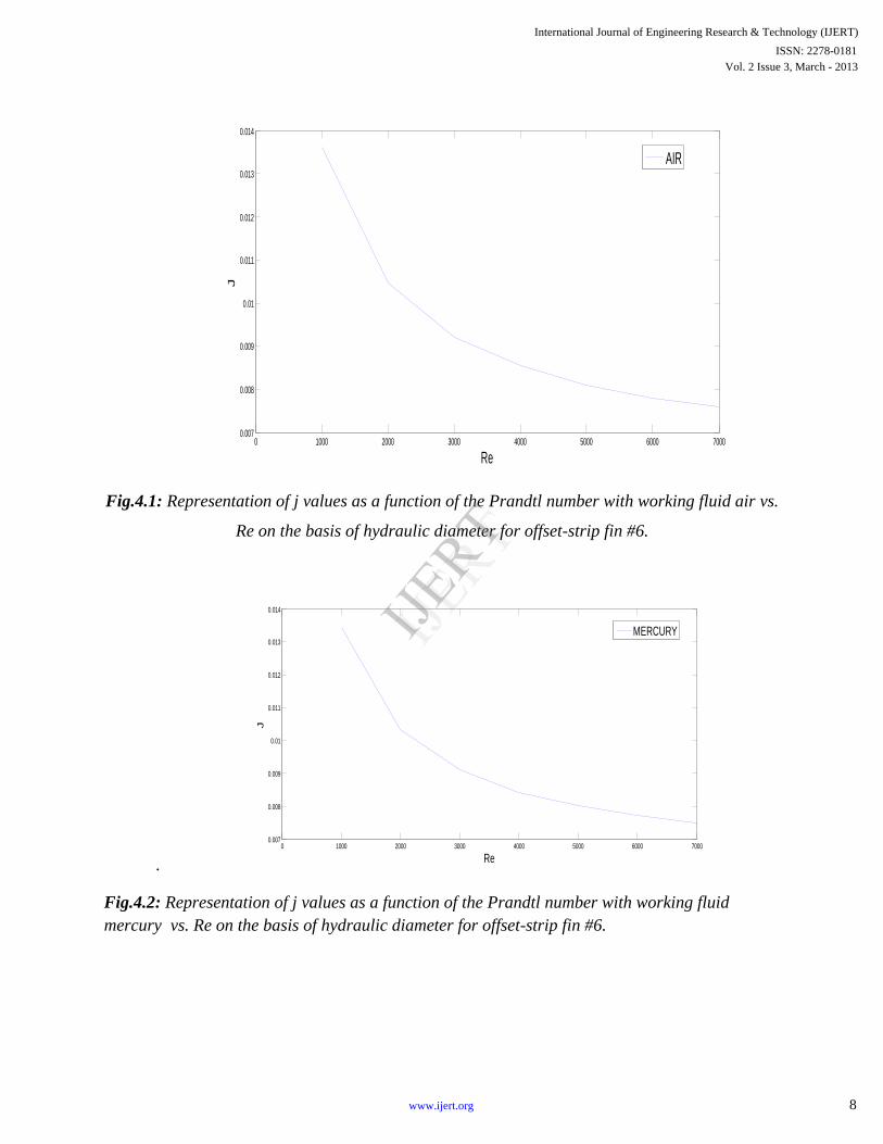
Fig.4.1: Representation of j values as a function of the Prandtl number with working fluid air vs.
Re on the basis of hydraulic diameter for offset-strip fin #6.
.
Fig.4.2: Representation of j values as a function of the Prandtl number with working fluid
mercury vs. Re on the basis of hydraulic diameter for offset-strip fin #6.
0 1000 2000 3000 4000 5000 6000 70000.007
0.008
0.009
0.01
0.011
0.012
0.013
0.014
Re
J
AIR
0 1000 2000 3000 4000 5000 6000 70000.007
0.008
0.009
0.01
0.011
0.012
0.013
0.014
Re
J
MERCURY
International Journal of Engineering Research & Technology (IJERT)
Vol. 2 Issue 3, March - 2013ISSN: 2278-0181
8www.ijert.org
IJERT
IJERT
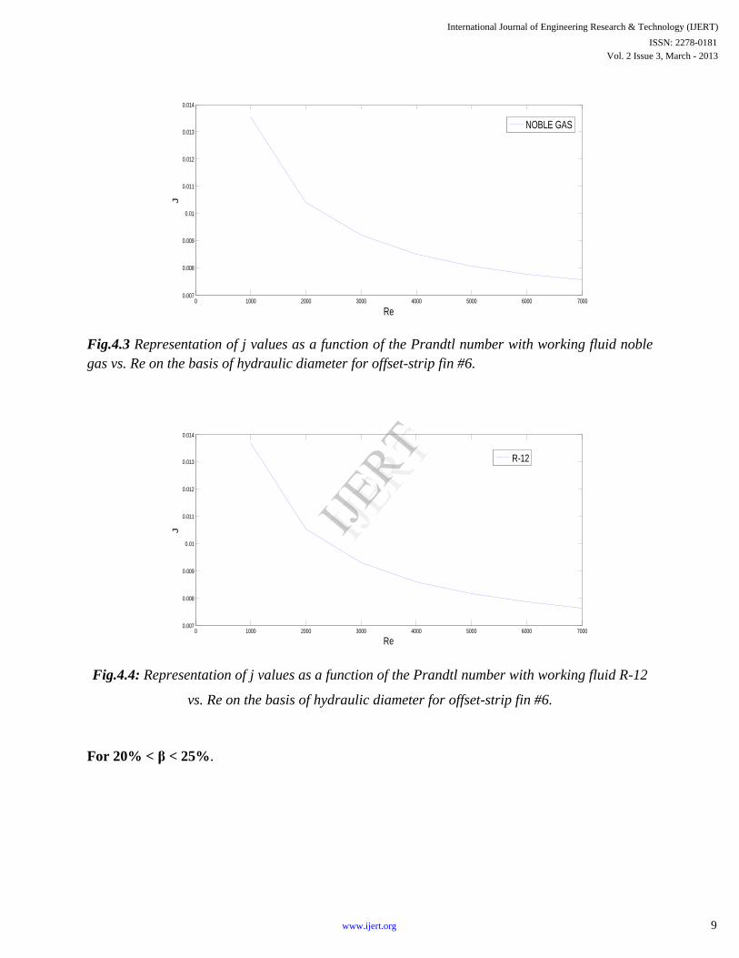
Fig.4.3 Representation of j values as a function of the Prandtl number with working fluid noble
gas vs. Re on the basis of hydraulic diameter for offset-strip fin #6.
Fig.4.4: Representation of j values as a function of the Prandtl number with working fluid R-12
vs. Re on the basis of hydraulic diameter for offset-strip fin #6.
For 20% < β < 25%.
0 1000 2000 3000 4000 5000 6000 70000.007
0.008
0.009
0.01
0.011
0.012
0.013
0.014
Re
J
NOBLE GAS
0 1000 2000 3000 4000 5000 6000 70000.007
0.008
0.009
0.01
0.011
0.012
0.013
0.014
Re
J
R-12
International Journal of Engineering Research & Technology (IJERT)
Vol. 2 Issue 3, March - 2013ISSN: 2278-0181
9www.ijert.org
IJERT
IJERT
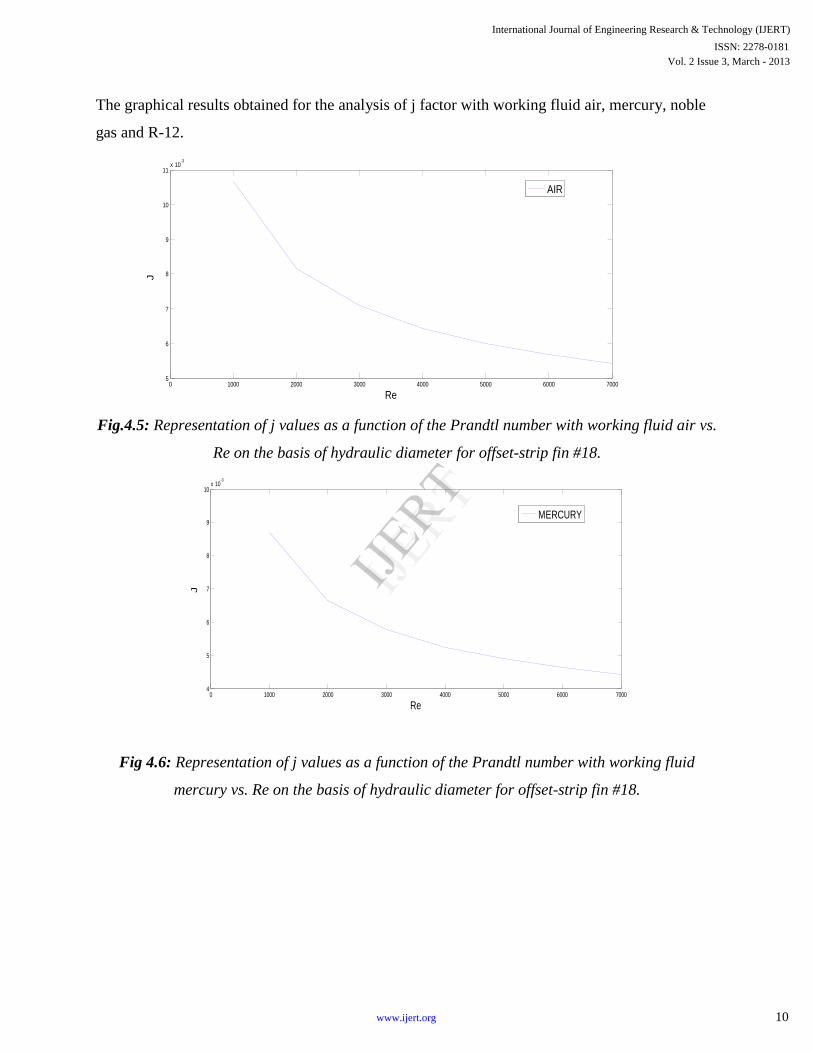
The graphical results obtained for the analysis of j factor with working fluid air, mercury, noble
gas and R-12.
Fig.4.5: Representation of j values as a function of the Prandtl number with working fluid air vs.
Re on the basis of hydraulic diameter for offset-strip fin #18.
Fig 4.6: Representation of j values as a function of the Prandtl number with working fluid
mercury vs. Re on the basis of hydraulic diameter for offset-strip fin #18.
0 1000 2000 3000 4000 5000 6000 70005
6
7
8
9
10
11x 10
-3
Re
J
AIR
0 1000 2000 3000 4000 5000 6000 70004
5
6
7
8
9
10x 10
-3
Re
J
MERCURY
International Journal of Engineering Research & Technology (IJERT)
Vol. 2 Issue 3, March - 2013ISSN: 2278-0181
10www.ijert.org
IJERT
IJERT
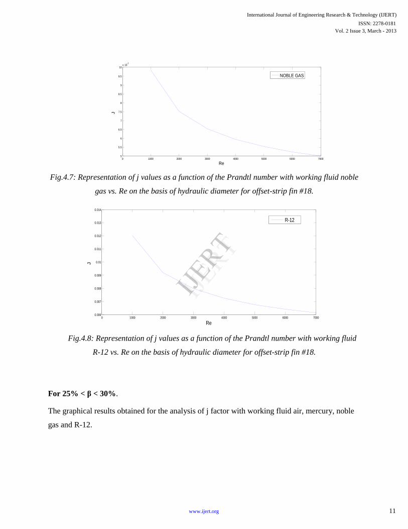
Fig.4.7: Representation of j values as a function of the Prandtl number with working fluid noble
gas vs. Re on the basis of hydraulic diameter for offset-strip fin #18.
Fig.4.8: Representation of j values as a function of the Prandtl number with working fluid
R-12 vs. Re on the basis of hydraulic diameter for offset-strip fin #18.
For 25% < β < 30%.
The graphical results obtained for the analysis of j factor with working fluid air, mercury, noble
gas and R-12.
0 1000 2000 3000 4000 5000 6000 70000.006
0.007
0.008
0.009
0.01
0.011
0.012
0.013
0.014
Re
J
R-12
0 1000 2000 3000 4000 5000 6000 70005
5.5
6
6.5
7
7.5
8
8.5
9
9.5
10x 10
-3
Re
J
NOBLE GAS
International Journal of Engineering Research & Technology (IJERT)
Vol. 2 Issue 3, March - 2013ISSN: 2278-0181
11www.ijert.org
IJERT
IJERT
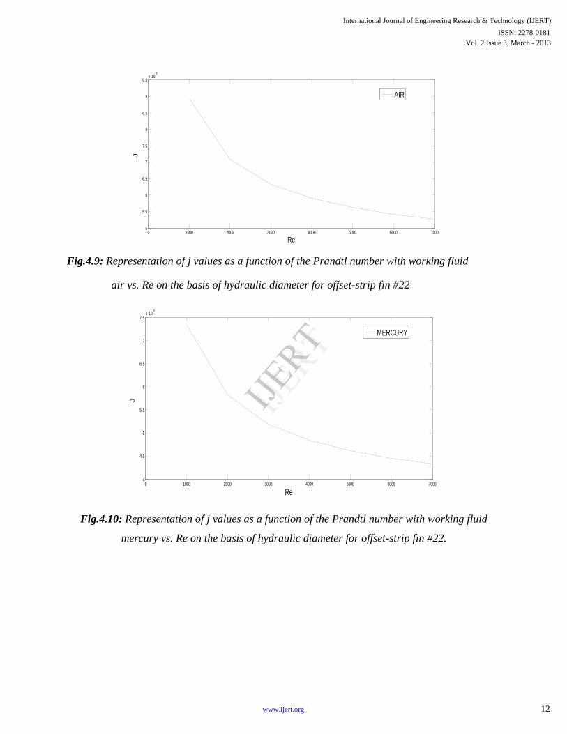
Fig.4.9: Representation of j values as a function of the Prandtl number with working fluid
air vs. Re on the basis of hydraulic diameter for offset-strip fin #22
Fig.4.10: Representation of j values as a function of the Prandtl number with working fluid
mercury vs. Re on the basis of hydraulic diameter for offset-strip fin #22.
0 1000 2000 3000 4000 5000 6000 70005
5.5
6
6.5
7
7.5
8
8.5
9
9.5x 10
-3
Re
J
AIR
0 1000 2000 3000 4000 5000 6000 70004
4.5
5
5.5
6
6.5
7
7.5x 10
-3
Re
J
MERCURY
International Journal of Engineering Research & Technology (IJERT)
Vol. 2 Issue 3, March - 2013ISSN: 2278-0181
12www.ijert.org
IJERT
IJERT
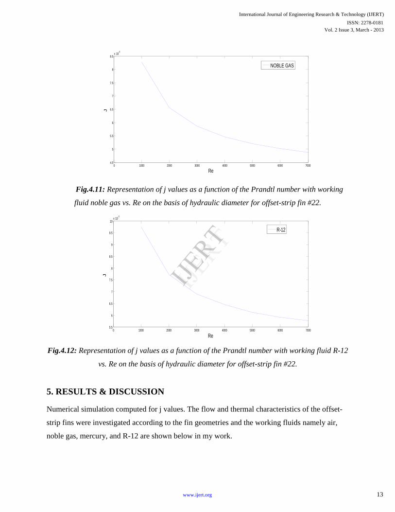
Fig.4.11: Representation of j values as a function of the Prandtl number with working
fluid noble gas vs. Re on the basis of hydraulic diameter for offset-strip fin #22.
Fig.4.12: Representation of j values as a function of the Prandtl number with working fluid R-12
vs. Re on the basis of hydraulic diameter for offset-strip fin #22.
5. RESULTS & DISCUSSION
Numerical simulation computed for j values. The flow and thermal characteristics of the offset-
strip fins were investigated according to the fin geometries and the working fluids namely air,
noble gas, mercury, and R-12 are shown below in my work.
0 1000 2000 3000 4000 5000 6000 70004.5
5
5.5
6
6.5
7
7.5
8
8.5x 10
-3
Re
J
NOBLE GAS
0 1000 2000 3000 4000 5000 6000 70005.5
6
6.5
7
7.5
8
8.5
9
9.5
10x 10
-3
Re
J
R-12
International Journal of Engineering Research & Technology (IJERT)
Vol. 2 Issue 3, March - 2013ISSN: 2278-0181
13www.ijert.org
IJERT
IJERT
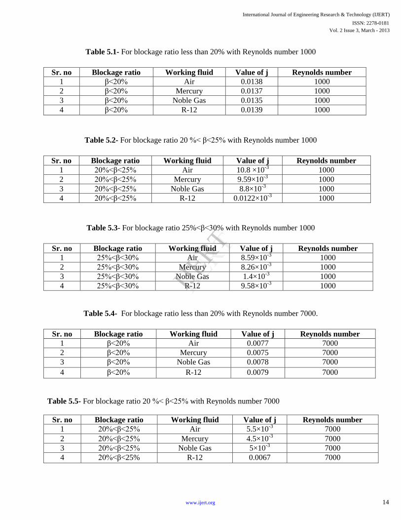
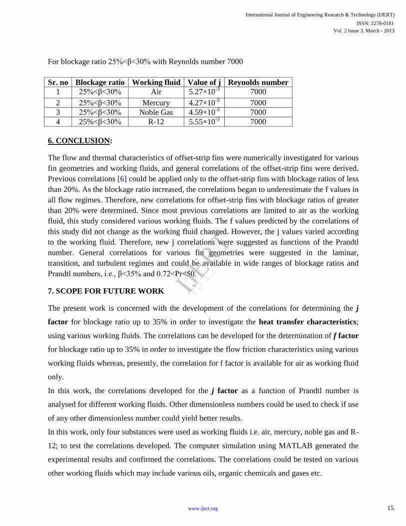
Table 5.1- For blockage ratio less than 20% with Reynolds number 1000
Sr. no Blockage ratio Working fluid Value of j Reynolds number
1 β<20% Air 0.0138 1000
2 β<20% Mercury 0.0137 1000
3 β<20% Noble Gas 0.0135 1000
4 β<20% R-12 0.0139 1000
Table 5.2- For blockage ratio 20 %< β<25% with Reynolds number 1000
Sr. no Blockage ratio Working fluid Value of j Reynolds number
1 20%<β<25% Air 10.8 ×10⁻³
1000
2 20%<β<25% Mercury 9.59×10⁻³
1000
3 20%<β<25% Noble Gas 8.8×10⁻³
1000
4 20%<β<25% R-12 0.0122×10⁻³
1000
Table 5.3- For blockage ratio 25%<β<30% with Reynolds number 1000
Sr. no Blockage ratio Working fluid Value of j Reynolds number
1 25%<β<30% Air 8.59×10⁻³
1000
2 25%<β<30% Mercury 8.26×10⁻³
1000
3 25%<β<30% Noble Gas 1.4×10⁻³
1000
4 25%<β<30% R-12 9.58×10⁻³
1000
Table 5.4- For blockage ratio less than 20% with Reynolds number 7000.
Sr. no Blockage ratio Working fluid Value of j Reynolds number
1 β<20% Air 0.0077 7000
2 β<20% Mercury 0.0075 7000
3 β<20% Noble Gas 0.0078 7000
4 β<20% R-12 0.0079 7000
Table 5.5- For blockage ratio 20 %< β<25% with Reynolds number 7000
Sr. no Blockage ratio Working fluid Value of j Reynolds number
1 20%<β<25% Air 5.5×10⁻³
7000
2 20%<β<25% Mercury 4.5×10⁻³
7000
3 20%<β<25% Noble Gas 5×10⁻³
7000
4 20%<β<25% R-12 0.0067
7000
International Journal of Engineering Research & Technology (IJERT)
Vol. 2 Issue 3, March - 2013ISSN: 2278-0181
14www.ijert.org
IJERT
IJERT
For blockage ratio 25%<β<30% with Reynolds number 7000
Sr. no Blockage ratio Working fluid Value of j Reynolds number
1 25%<β<30% Air 5.27×10⁻³
7000
2 25%<β<30% Mercury 4.27×10⁻³
7000
3 25%<β<30% Noble Gas 4.59×10⁻³
7000
4 25%<β<30% R-12 5.55×10⁻³
7000
6. CONCLUSION:
The flow and thermal characteristics of offset-strip fins were numerically investigated for various
fin geometries and working fluids, and general correlations of the offset-strip fins were derived.
Previous correlations [6] could be applied only to the offset-strip fins with blockage ratios of less
than 20%. As the blockage ratio increased, the correlations began to underestimate the f values in
all flow regimes. Therefore, new correlations for offset-strip fins with blockage ratios of greater
than 20% were determined. Since most previous correlations are limited to air as the working
fluid, this study considered various working fluids. The f values predicted by the correlations of
this study did not change as the working fluid changed. However, the j values varied according
to the working fluid. Therefore, new j correlations were suggested as functions of the Prandtl
number. General correlations for various fin geometries were suggested in the laminar,
transition, and turbulent regimes and could be available in wide ranges of blockage ratios and
Prandtl numbers, i.e., β<35% and 0.72<Pr<50.
7. SCOPE FOR FUTURE WORK
The present work is concerned with the development of the correlations for determining the j
factor for blockage ratio up to 35% in order to investigate the heat transfer characteristics;
using various working fluids. The correlations can be developed for the determination of f factor
for blockage ratio up to 35% in order to investigate the flow friction characteristics using various
working fluids whereas, presently, the correlation for f factor is available for air as working fluid
only.
In this work, the correlations developed for the j factor as a function of Prandtl number is
analysed for different working fluids. Other dimensionless numbers could be used to check if use
of any other dimensionless number could yield better results.
In this work, only four substances were used as working fluids i.e. air, mercury, noble gas and R-
12; to test the correlations developed. The computer simulation using MATLAB generated the
experimental results and confirmed the correlations. The correlations could be tested on various
other working fluids which may include various oils, organic chemicals and gases etc.
International Journal of Engineering Research & Technology (IJERT)
Vol. 2 Issue 3, March - 2013ISSN: 2278-0181
15www.ijert.org
IJERT
IJERT
REFERENCES:-
[1] W.M. Kays, L. London, Compact Heat Exchangers, McGraw-Hill, New York,
1984.
[2] S.V. Manson, Correlations of heat transfer data and of friction data for interrupted plane fins
staggered in successive rows, NACA technical note 2237, National Advisory Committee for
Aeronautics, Washington DC, 1950.
[3] A.R. Wieting, Empirical correlations for heat transfer and flow friction characteristics of
rectangular offset-fin plate-fin heat exchangers, J. Heat Transfer 30 (1975) 69–84.
[4] S. Mochizuki, Y. Yagi, W-J. Yang, Transport phenomena in stacks of interrupted parallel
plate surfaces, Exp. Heat Transfer 1 (1987) 127–140.
[5] H.M. Joshi, R.L. Webb, Heat-transfer and friction in the offset strip fin heat exchanger, Int. J.
Heat Mass Transfer 30 (1987) 69–84.
[6] R.M. Manglik, A.E. Bergles, Heat-transfer and pressure-drop correlations for the rectangular
offset strip fin compact heat-exchanger, Exp. Thermal Fluid Sci. 10 (1995) 171–180.
[7] F.V. Tinaut, A. Meglar, A. Ali, Correlations for heat-transfer and flow friction characteristics
of compact plate-type heat-exchanger, Int. J. Heat Mass Transfer 35 (1992) 1659–1665.
[8] S. Hu, K.E. Herold, Prandtl number effect on offset fin heat-exchanger performance –
experimental results, Int. J. Heat Mass Transfer 38 (1995) 1053–1061.
[9] Y.S. Muzychka, Analytical and experimental study of fluid friction and heat transfer in low
Reynolds number flow heat exchangers, Ph.D. Thesis, University of Waterloo, Canada, 1999.
[10] Y.S. Muzychka, M.M. Yovanovich, Modeling the f and j characteristics for transverse flow
through an offset strip fin at low Reynolds number, Enhanc. Heat Transfer 8 (2001) 243–259.
[11] K. Park, D-H. Choi, K-S. Lee, Numerical shape optimization for high performance of a heat
sink with pin-fins, Numer. Heat Transfer A. Appl. 46 (2004) 909–927.
[12] G.N. Vanderplaats, Numerical Optimization Techniques for Engineering Design with
Applications, McGraw-Hill, New York, 1984.
[13] J.I. Madsen, M. Langyhjem, Multifidelity response surface approximations for the optimum
design of diffuser flows, Opt. Eng. 2 (2001) 453–468.
[14] J.F. Rodriguez, J.E. Renaud, B.A. Wujek, R.V. Tappeta, Trust region model management in
multidisciplinary design optimization, J. Comput. Appl. Math. 124 (2000) 139–154.
International Journal of Engineering Research & Technology (IJERT)
Vol. 2 Issue 3, March - 2013ISSN: 2278-0181
16www.ijert.org
IJERT
IJERT
[15] S-J. Oh, K-S. Lee, S-J. Moon, Optimal design of a parallel-flow heat exchanger using a
response surface methodology, Numer. Heat Transfer A. Appl. 49 (2006) 411–426.
[16] P. Li, K-Y. Kim, Multiobjective optimization of staggered elliptical pin-fin arrays, Numer.
Heat Transfer A. Appl. 53 (2008) 418–431.
[17] M.S Kim,Jonghyeok Lee,Se-Jin Yook ,Kwan-Soo Lee Correlations and optimization of
heat strip fins.Int.journal of heat and mass transfer,54 (2011) 2073-2078.
International Journal of Engineering Research & Technology (IJERT)
Vol. 2 Issue 3, March - 2013ISSN: 2278-0181
17www.ijert.org
IJERT
IJERT