Embed Size (px)
Citation preview
International Journal of Science Vol.4 No.7 2017 ISSN: 1813-4890
164
Analysis of the overall stability of castellated beams under bending and torsion
Shier Dong a, Peng Wang b
School of civil engineering and architecture, Southwest Petroleum University, Chengdu 610500,
China
[email protected], [email protected]
Abstract
Castellated beam is a steel structure with holes in the web of I-section steel beam after a certain
process. Castellated beam has the characteristics of steel saving, high bearing capacity and
attracitve appearance, which has been widely used in practical engineering. However, due to
the existence of eccentricity in practical engineering, castellated beam always supports the joint
action of bending moment and tortion at the same time which makes the occurence of unstable
failure before the strength failue. Domestic and foreign scholars on the research of the beam
condition of bending and torsion are mostly based on plain girder. In addition, on the basis of
it, this paper has combined the finite element software ABAQUS to calculated the critical
moment of Hexagonal hole castellated beams under the situation of different eccentricity,
different pore ratio and hole spacing,which give the influence trend of each influence factor ,so
as to be referenced in the design of castellated beam.
Keywords
Castellated beam,Overall stability, Bend torsion condition,The finite element analysis.
1. Introduction
The castellated beam is one of the I-shaped steel structures, and the stability theory of the I-shaped
steel structure has been studied for a long time, and many remarkable achievements have been
achieved. But in China's "code for design of steel structure" (GB50017-2003)[1] there is no formula
of overall stability of castellated beams are bending state, only the solid web steel beam under
transverse uniform load, concentrated the overall stability of solid beams and biaxial bending load, calculation formula. Our technical specifications "cold-formed steel structure" (GB50018-2002) [2]
formula of overall stability under combined bending and torsion bearing capacity of cold-formed steel
was also given only, only for thin-walled steel structure. Thus it can be seen that the formulas
prescribed by the relevant codes do not give the stability formula of the castellated beam under the
bending and torsion state, and can not solve a large number of practical engineering problems. The
whole honeycomb beam in and under bending and twisting stability calculation formula without clear
validation, such components in practical engineering design, the designer can only be based on solid
web beams combined with practical experience in engineering design, it may cause unnecessary
waste, at the same time under simply supported castellated beam combined bending and torsion in
flexural torsional buckling is how to influence the critical moment of simply supported castellated beams, the influence, and different span, section size, load type, load position change of lateral
torsional buckling strength of I-shaped castellated beams is how to change, these are to be further the
theoretical calculation and finite element analysis. There are two kinds of domestic research methods
to study their overall stability. One is the theoretical study of energy method, and the other is the
theoretical study of finite element method [3,4].
ABAQUS software is developed by Dassault SIMULIA company developed for static and quasi static analysis, modal analysis, transient analysis, buckling analysis, fatigue analysis, structure analysis, can
also sound and flow coupling analysis, acoustic coupling solid, especially the analysis of very
complex problems and can simulate the highly nonlinear problems, ABAQUS nonlinear finite
International Journal of Science Vol.4 No.7 2017 ISSN: 1813-4890
165
element analysis software is extremely powerful. Based on the above considerations, the ABAQUS
software is used to analyze the overall stability of the hexagonal hole simply supported beam under
bending and torsion in this paper.
2. Establish a finite element model of castellated beam
2.1 ABAQUS model unit type selection
The I-shaped steel is composed of three pieces of welded steel plate, plate thickness thin, relatively
large, so it is suitable for SHELL unit in ABAQUS. In this paper, the castellated beam is made of
Q235 steel, the elastic modulus of steel and Poisson's ratio of 52.1 10E N/mm2. According to the
mechanics of materials, 52 1 8.07 10G E MPa can be obtained. The essence of finite
element analysis is to reduce the continuous model to discrete model, and the more discrete model, the closer it is to the actual situation. In the finite element analysis of the honeycomb beam, each
model should be divided according to the specific size in each part, and the maximum grid size at the
cross section is controlled at around 25mm. The calculation speed to meet the accuracy requirements
and to ensure that the case, because the flange shape is regular, which is divided into rectangular grid,
and the web due to the hole, the model itself is not continuous, so the shape of the triangle mesh web
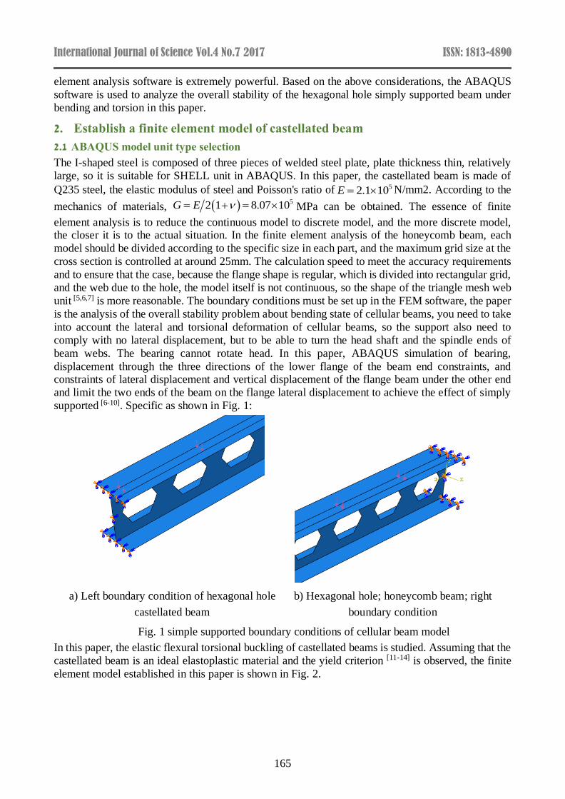
unit [5,6,7] is more reasonable. The boundary conditions must be set up in the FEM software, the paper
is the analysis of the overall stability problem about bending state of cellular beams, you need to take
into account the lateral and torsional deformation of cellular beams, so the support also need to
comply with no lateral displacement, but to be able to turn the head shaft and the spindle ends of
beam webs. The bearing cannot rotate head. In this paper, ABAQUS simulation of bearing,
displacement through the three directions of the lower flange of the beam end constraints, and constraints of lateral displacement and vertical displacement of the flange beam under the other end
and limit the two ends of the beam on the flange lateral displacement to achieve the effect of simply
supported [6-10]. Specific as shown in Fig. 1:
a) Left boundary condition of hexagonal hole
castellated beam
b) Hexagonal hole; honeycomb beam; right
boundary condition
Fig. 1 simple supported boundary conditions of cellular beam model
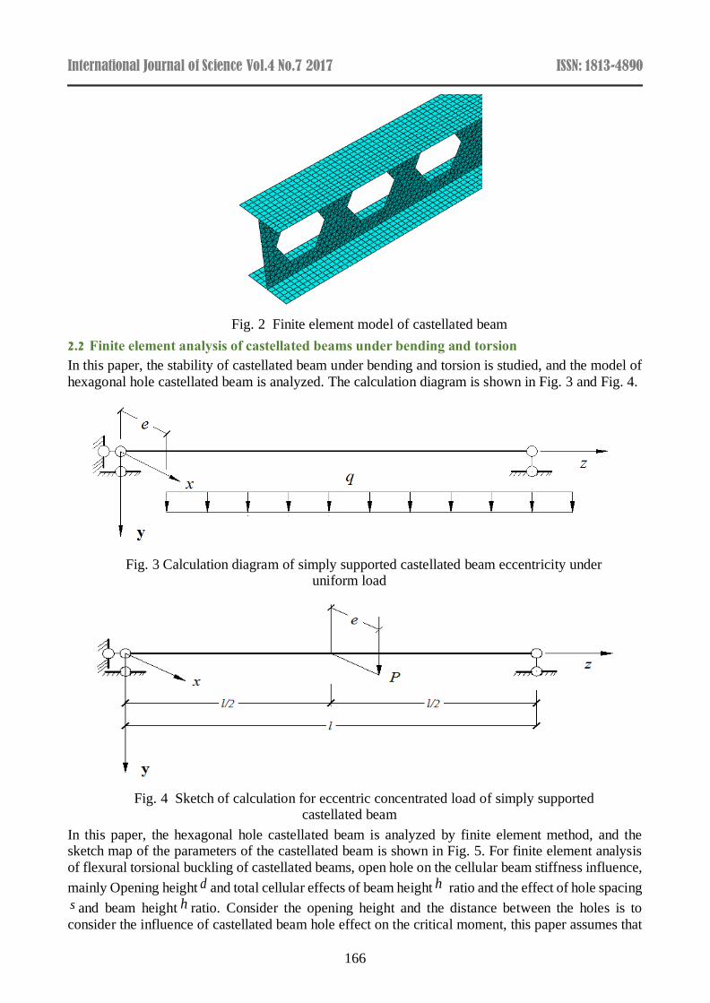
In this paper, the elastic flexural torsional buckling of castellated beams is studied. Assuming that the
castellated beam is an ideal elastoplastic material and the yield criterion [11-14] is observed, the finite
element model established in this paper is shown in Fig. 2.
International Journal of Science Vol.4 No.7 2017 ISSN: 1813-4890
166
Fig. 2 Finite element model of castellated beam
2.2 Finite element analysis of castellated beams under bending and torsion
In this paper, the stability of castellated beam under bending and torsion is studied, and the model of
hexagonal hole castellated beam is analyzed. The calculation diagram is shown in Fig. 3 and Fig. 4.
Fig. 3 Calculation diagram of simply supported castellated beam eccentricity under uniform load
Fig. 4 Sketch of calculation for eccentric concentrated load of simply supported castellated beam
In this paper, the hexagonal hole castellated beam is analyzed by finite element method, and the sketch map of the parameters of the castellated beam is shown in Fig. 5. For finite element analysis
of flexural torsional buckling of castellated beams, open hole on the cellular beam stiffness influence,
mainly Opening height d and total cellular effects of beam height h ratio and the effect of hole spacing
s and beam height h ratio. Consider the opening height and the distance between the holes is to
consider the influence of castellated beam hole effect on the critical moment, this paper assumes that
International Journal of Science Vol.4 No.7 2017 ISSN: 1813-4890
167
the sum of the opening height d and the opening spacing s is the castellated beam height h , namely
d s h ; according to the beam section size commonly used in practical engineering, the basic
model of the beam span, size and span Table 1 shows.
Fig. 5 Sketch of calculation parameters of castellated beams with six side holes
Table 1 basic section size and span of model beam
Component number Component specification Calculated span l (m)
1 400×180×10×12 4.8
2 400×180×10×12 6
3 400×180×10×12 12
4 500×250×12×15 4.8
5 500×250×12×15 6
6 500×250×12×15 12
3. Finite element analysis of flexural torsional buckling of simply supported castellated beams with hexagonal holes under bending and torsion
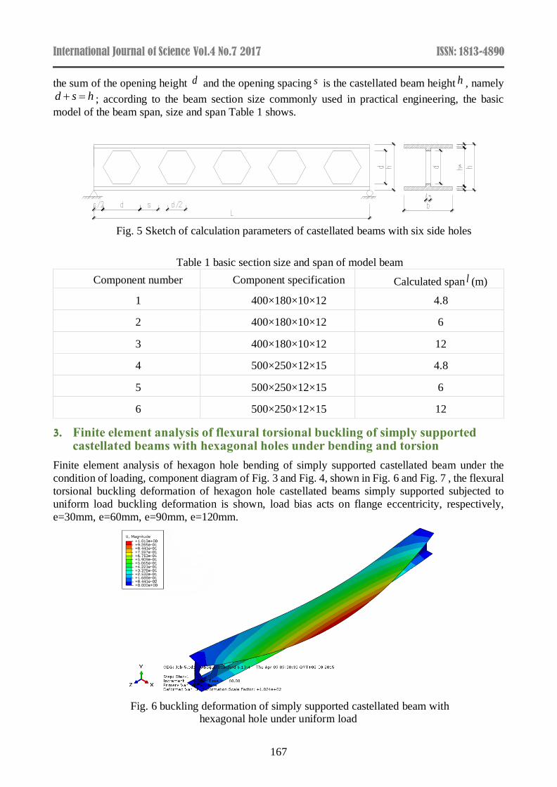
Finite element analysis of hexagon hole bending of simply supported castellated beam under the
condition of loading, component diagram of Fig. 3 and Fig. 4, shown in Fig. 6 and Fig. 7 , the flexural
torsional buckling deformation of hexagon hole castellated beams simply supported subjected to
uniform load buckling deformation is shown, load bias acts on flange eccentricity, respectively,
e=30mm, e=60mm, e=90mm, e=120mm.
Fig. 6 buckling deformation of simply supported castellated beam with hexagonal hole under uniform load
International Journal of Science Vol.4 No.7 2017 ISSN: 1813-4890
168
Fig. 7 buckling deformation of simply supported castellated beam with hexagonal hole under concentrated force
3.1 Analysis of factors affecting the overall stability of Castellated Beams
The change of a quantity is usually affected by a number of parameters. For the case of multivariable,
the more commonly used method is the control variable method, which simplifies the problem of
multiple variables into a single variable problem. The so-called control variable method is that every
time a variable is taken as the research factor, the remaining variables are not changed under certain
conditions. The change of the influence of the variable on the research question is analyzed. The
control variable method is convenient for research and analysis, and is widely used in various research fields.
The overall stability of castellated beams is mainly affected by porosity, shape of openings, span
depth ratio and other factors. It is assumed that the ABAQUS value is the critical critical moment of
the component and the effect of various factors on the overall stability of the castellated beam is
investigated.
The influence of eccentricity on the overall stability of Castellated Beams
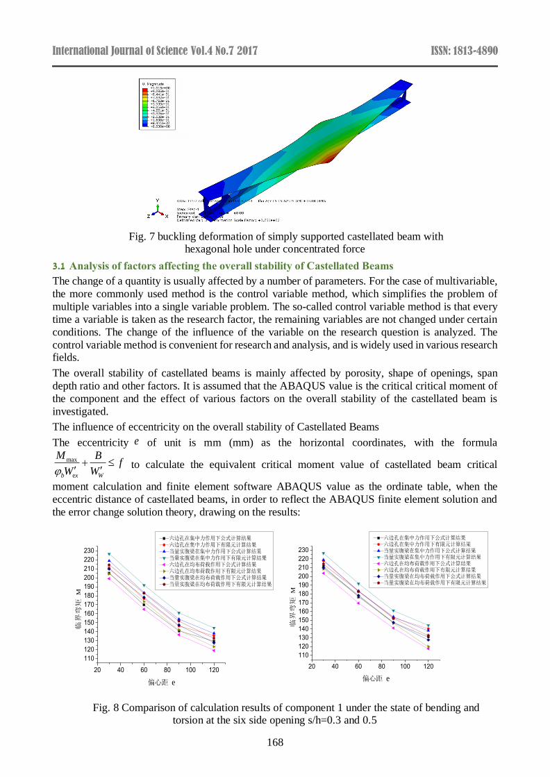
The eccentricity e of unit is mm (mm) as the horizontal coordinates, with the formula
max
eb x W
M Bf
W W
to calculate the equivalent critical moment value of castellated beam critical
moment calculation and finite element software ABAQUS value as the ordinate table, when the
eccentric distance of castellated beams, in order to reflect the ABAQUS finite element solution and
the error change solution theory, drawing on the results:
Fig. 8 Comparison of calculation results of component 1 under the state of bending and torsion at the six side opening s/h=0.3 and 0.5
20 40 60 80 100 120
110
120
130
140
150
160
170
180
190
200
210
220
230
六边孔在集中力作用下公式计算结果 六边孔在集中力作用下有限元计算结果当量实腹梁在集中力作用下公式计算结果当量实腹梁在集中力作用下有限元计算结果六边孔在均布荷载作用下公式计算结果六边孔在均布荷载作用下有限元计算结果当量实腹梁在均布荷载作用下公式计算结果当量实腹梁在均布荷载作用下有限元计算结果
临界
弯矩
M
偏心距 e
20 40 60 80 100 120
110
120
130
140
150
160
170
180
190
200
210
220
230
六边孔在集中力作用下公式计算结果 六边孔在集中力作用下有限元计算结果当量实腹梁在集中力作用下公式计算结果当量实腹梁在集中力作用下有限元计算结果六边孔在均布荷载作用下公式计算结果六边孔在均布荷载作用下有限元计算结果当量实腹梁在均布荷载作用下公式计算结果当量实腹梁在均布荷载作用下有限元计算结果
临界弯矩
M
偏心距 e
International Journal of Science Vol.4 No.7 2017 ISSN: 1813-4890
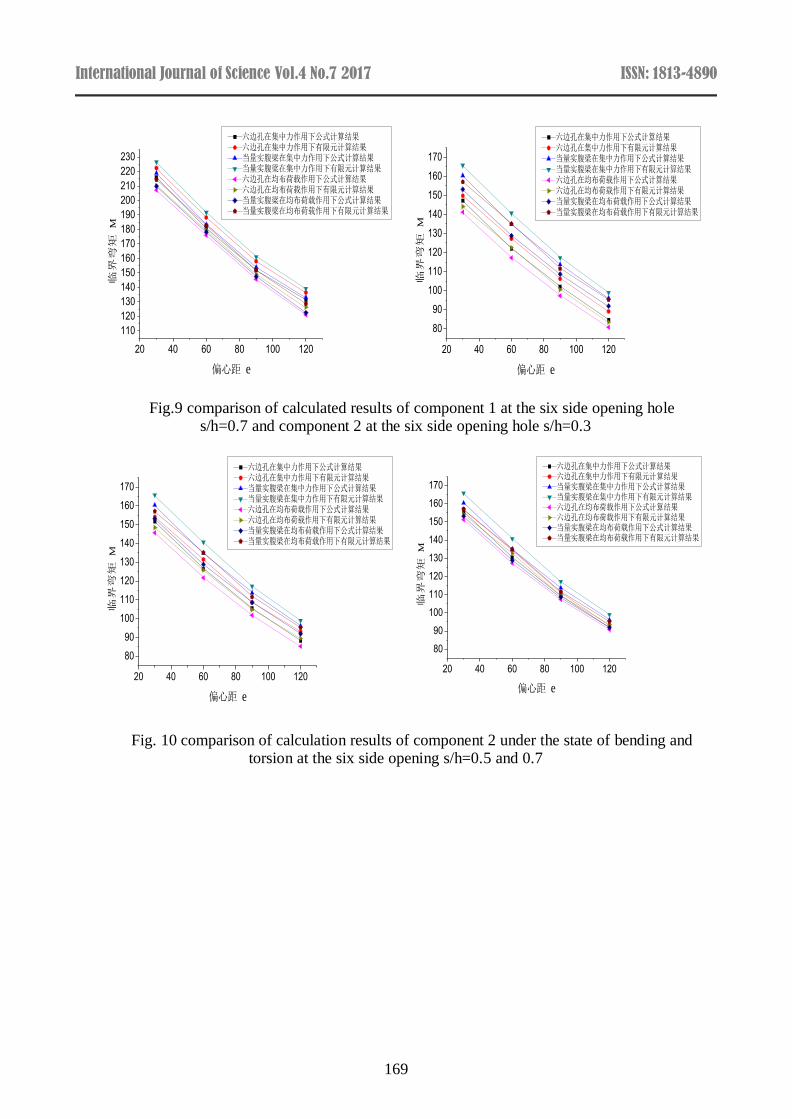
169
Fig.9 comparison of calculated results of component 1 at the six side opening hole s/h=0.7 and component 2 at the six side opening hole s/h=0.3
Fig. 10 comparison of calculation results of component 2 under the state of bending and torsion at the six side opening s/h=0.5 and 0.7
20 40 60 80 100 120
110
120
130
140
150
160
170
180
190
200
210
220
230
六边孔在集中力作用下公式计算结果 六边孔在集中力作用下有限元计算结果当量实腹梁在集中力作用下公式计算结果当量实腹梁在集中力作用下有限元计算结果六边孔在均布荷载作用下公式计算结果六边孔在均布荷载作用下有限元计算结果当量实腹梁在均布荷载作用下公式计算结果当量实腹梁在均布荷载作用下有限元计算结果
临界弯矩
M
偏心距 e
20 40 60 80 100 120
80
90
100
110
120
130
140
150
160
170
六边孔在集中力作用下公式计算结果 六边孔在集中力作用下有限元计算结果当量实腹梁在集中力作用下公式计算结果当量实腹梁在集中力作用下有限元计算结果六边孔在均布荷载作用下公式计算结果六边孔在均布荷载作用下有限元计算结果当量实腹梁在均布荷载作用下公式计算结果当量实腹梁在均布荷载作用下有限元计算结果
临界
弯矩
M
偏心距 e
20 40 60 80 100 120
80
90
100
110
120
130
140
150
160
170
六边孔在集中力作用下公式计算结果 六边孔在集中力作用下有限元计算结果当量实腹梁在集中力作用下公式计算结果当量实腹梁在集中力作用下有限元计算结果六边孔在均布荷载作用下公式计算结果六边孔在均布荷载作用下有限元计算结果当量实腹梁在均布荷载作用下公式计算结果当量实腹梁在均布荷载作用下有限元计算结果
临界弯矩
M
偏心距 e
20 40 60 80 100 120
80
90
100
110
120
130
140
150
160
170
六边孔在集中力作用下公式计算结果 六边孔在集中力作用下有限元计算结果当量实腹梁在集中力作用下公式计算结果当量实腹梁在集中力作用下有限元计算结果六边孔在均布荷载作用下公式计算结果六边孔在均布荷载作用下有限元计算结果当量实腹梁在均布荷载作用下公式计算结果当量实腹梁在均布荷载作用下有限元计算结果
临界
弯矩
M
偏心距 e
International Journal of Science Vol.4 No.7 2017 ISSN: 1813-4890
170
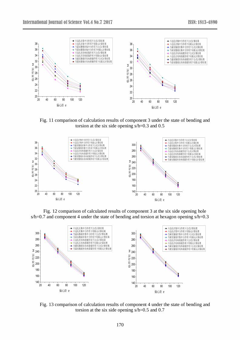
Fig. 11 comparison of calculation results of component 3 under the state of bending and
torsion at the six side opening s/h=0.3 and 0.5
Fig. 12 comparison of calculated results of component 3 at the six side opening hole
s/h=0.7 and component 4 under the state of bending and torsion at hexagon opening s/h=0.3
Fig. 13 comparison of calculation results of component 4 under the state of bending and torsion at the six side opening s/h=0.5 and 0.7
20 40 60 80 100 12020
22
24
26
28
30
32
34
36
38六边孔在集中力作用下公式计算结果 六边孔在集中力作用下有限元计算结果当量实腹梁在集中力作用下公式计算结果当量实腹梁在集中力作用下有限元计算结果六边孔在均布荷载作用下公式计算结果六边孔在均布荷载作用下有限元计算结果当量实腹梁在均布荷载作用下公式计算结果当量实腹梁在均布荷载作用下有限元计算结果
临界
弯矩
M
偏心距 e20 40 60 80 100 120
20
22
24
26
28
30
32
34
36
38六边孔在集中力作用下公式计算结果 六边孔在集中力作用下有限元计算结果当量实腹梁在集中力作用下公式计算结果当量实腹梁在集中力作用下有限元计算结果六边孔在均布荷载作用下公式计算结果六边孔在均布荷载作用下有限元计算结果当量实腹梁在均布荷载作用下公式计算结果当量实腹梁在均布荷载作用下有限元计算结果
临界弯矩
M
偏心距 e
20 40 60 80 100 12020
22
24
26
28
30
32
34
36
38六边孔在集中力作用下公式计算结果 六边孔在集中力作用下有限元计算结果当量实腹梁在集中力作用下公式计算结果当量实腹梁在集中力作用下有限元计算结果六边孔在均布荷载作用下公式计算结果六边孔在均布荷载作用下有限元计算结果当量实腹梁在均布荷载作用下公式计算结果当量实腹梁在均布荷载作用下有限元计算结果
临界弯矩
M
偏心距 e
20 40 60 80 100 120140
160
180
200
220
240
260
280
300
六边孔在集中力作用下公式计算结果 六边孔在集中力作用下有限元计算结果当量实腹梁在集中力作用下公式计算结果当量实腹梁在集中力作用下有限元计算结果六边孔在均布荷载作用下公式计算结果六边孔在均布荷载作用下有限元计算结果当量实腹梁在均布荷载作用下公式计算结果当量实腹梁在均布荷载作用下有限元计算结果
临界弯矩
M
偏心距 e
20 40 60 80 100 120140
160
180
200
220
240
260
280
300
六边孔在集中力作用下公式计算结果 六边孔在集中力作用下有限元计算结果当量实腹梁在集中力作用下公式计算结果当量实腹梁在集中力作用下有限元计算结果六边孔在均布荷载作用下公式计算结果六边孔在均布荷载作用下有限元计算结果当量实腹梁在均布荷载作用下公式计算结果当量实腹梁在均布荷载作用下有限元计算结果
临界弯矩
M
偏心距 e
20 40 60 80 100 120140
160
180
200
220
240
260
280
300
六边孔在集中力作用下公式计算结果 六边孔在集中力作用下有限元计算结果当量实腹梁在集中力作用下公式计算结果当量实腹梁在集中力作用下有限元计算结果六边孔在均布荷载作用下公式计算结果六边孔在均布荷载作用下有限元计算结果当量实腹梁在均布荷载作用下公式计算结果当量实腹梁在均布荷载作用下有限元计算结果
临界弯矩
M
偏心距 e
International Journal of Science Vol.4 No.7 2017 ISSN: 1813-4890
171
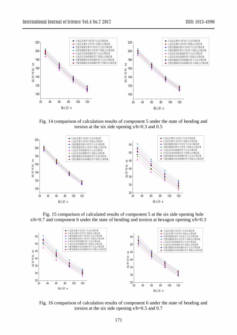
Fig. 14 comparison of calculation results of component 5 under the state of bending and torsion at the six side opening s/h=0.3 and 0.5
Fig. 15 comparison of calculated results of component 5 at the six side opening hole s/h=0.7 and component 6 under the state of bending and torsion at hexagon opening s/h=0.3
Fig. 16 comparison of calculation results of component 6 under the state of bending and torsion at the six side opening s/h=0.5 and 0.7
20 40 60 80 100 120
100
120
140
160
180
200
220六边孔在集中力作用下公式计算结果 六边孔在集中力作用下有限元计算结果当量实腹梁在集中力作用下公式计算结果当量实腹梁在集中力作用下有限元计算结果六边孔在均布荷载作用下公式计算结果六边孔在均布荷载作用下有限元计算结果当量实腹梁在均布荷载作用下公式计算结果当量实腹梁在均布荷载作用下有限元计算结果
临界弯矩
M
偏心距 e
20 40 60 80 100 120
100
120
140
160
180
200
220六边孔在集中力作用下公式计算结果 六边孔在集中力作用下有限元计算结果当量实腹梁在集中力作用下公式计算结果当量实腹梁在集中力作用下有限元计算结果六边孔在均布荷载作用下公式计算结果六边孔在均布荷载作用下有限元计算结果当量实腹梁在均布荷载作用下公式计算结果当量实腹梁在均布荷载作用下有限元计算结果
临界弯矩
M
偏心距 e
20 40 60 80 100 120
100
120
140
160
180
200
220六边孔在集中力作用下公式计算结果 六边孔在集中力作用下有限元计算结果当量实腹梁在集中力作用下公式计算结果当量实腹梁在集中力作用下有限元计算结果六边孔在均布荷载作用下公式计算结果六边孔在均布荷载作用下有限元计算结果当量实腹梁在均布荷载作用下公式计算结果当量实腹梁在均布荷载作用下有限元计算结果
临界弯矩
M
偏心距 e
20 40 60 80 100 12025
30
35
40
45
50
55
六边孔在集中力作用下公式计算结果 六边孔在集中力作用下有限元计算结果当量实腹梁在集中力作用下公式计算结果当量实腹梁在集中力作用下有限元计算结果六边孔在均布荷载作用下公式计算结果六边孔在均布荷载作用下有限元计算结果当量实腹梁在均布荷载作用下公式计算结果当量实腹梁在均布荷载作用下有限元计算结果
临界弯矩
M
偏心距 e
20 40 60 80 100 12025
30
35
40
45
50
55
六边孔在集中力作用下公式计算结果 六边孔在集中力作用下有限元计算结果当量实腹梁在集中力作用下公式计算结果当量实腹梁在集中力作用下有限元计算结果六边孔在均布荷载作用下公式计算结果六边孔在均布荷载作用下有限元计算结果当量实腹梁在均布荷载作用下公式计算结果当量实腹梁在均布荷载作用下有限元计算结果
临界弯矩
M
偏心距 e20 40 60 80 100 120
25
30
35
40
45
50
55
六边孔在集中力作用下公式计算结果 六边孔在集中力作用下有限元计算结果当量实腹梁在集中力作用下公式计算结果当量实腹梁在集中力作用下有限元计算结果六边孔在均布荷载作用下公式计算结果六边孔在均布荷载作用下有限元计算结果当量实腹梁在均布荷载作用下公式计算结果当量实腹梁在均布荷载作用下有限元计算结果
临界弯矩
M
偏心距 e
International Journal of Science Vol.4 No.7 2017 ISSN: 1813-4890
172
It can be summed up by the figure above:
(1) the uniform load for the calculation of the two kinds of load form eccentric concentrated force and eccentric load, when the eccentricity is the critical moment of smaller eccentric uniform critical
moment loads than the eccentric and concentrated load, so the castellated beam relative eccentric
concentrated load, eccentric load more unfavorable.
(2) obviously, due to eccentricity due to the existence of castellated beam bearing capacity of the overall decrease in honeycomb beam section size, span, opening a certain distance, the greater the
eccentricity is greater torque, the critical moment of castellated beams is smaller. When the
eccentricity is small (mm), the critical moment decreases with the increase of the eccentricity, and
the specific reflection in the diagram is that the slope is greater; with the increase of the eccentricity,
the critical moment changes gradually. With the increase of the span of the component, the overall
trend of each eccentric distance is consistent. For example, the total variation trend of the 1, 2 and 3
components at the eccentricity of 30mm, 60mm, 90mm and 120mm is the same.
(3) the overall trend summarized above, the finite element software ABAQUS calculation results than the theoretical calculation results to some, that formula is conservative, both eccentric and
concentrated load or eccentric load, with the increase of eccentricity will cause the decrease of the
critical moment, the hexagonal hole with a circular opening the difference in the same hole
eccentricity is small, but when the increasing trend changes from both eccentric and solid beams is
the same, it also illustrates the correctness and rationality of the finite element model.
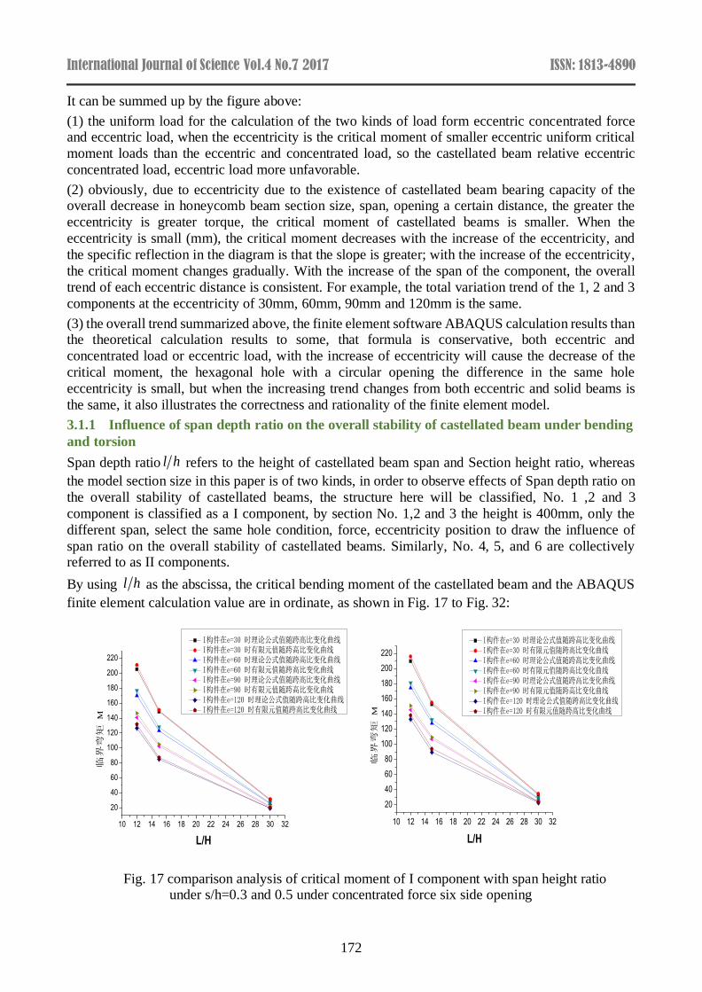
3.1.1 Influence of span depth ratio on the overall stability of castellated beam under bending
and torsion
Span depth ratio l h refers to the height of castellated beam span and Section height ratio, whereas
the model section size in this paper is of two kinds, in order to observe effects of Span depth ratio on
the overall stability of castellated beams, the structure here will be classified, No. 1 ,2 and 3
component is classified as a I component, by section No. 1,2 and 3 the height is 400mm, only the
different span, select the same hole condition, force, eccentricity position to draw the influence of
span ratio on the overall stability of castellated beams. Similarly, No. 4, 5, and 6 are collectively referred to as II components.
By using l h as the abscissa, the critical bending moment of the castellated beam and the ABAQUS
finite element calculation value are in ordinate, as shown in Fig. 17 to Fig. 32:
Fig. 17 comparison analysis of critical moment of I component with span height ratio under s/h=0.3 and 0.5 under concentrated force six side opening
10 12 14 16 18 20 22 24 26 28 30 32
20
40
60
80
100
120
140
160
180
200
220
临界弯矩
M
L/H
I构件在e=30 时理论公式值随跨高比变化曲线 I构件在e=30 时有限元值随跨高比变化曲线 I构件在e=60 时理论公式值随跨高比变化曲线 I构件在e=60 时有限元值随跨高比变化曲线 I构件在e=90 时理论公式值随跨高比变化曲线 I构件在e=90 时有限元值随跨高比变化曲线 I构件在e=120 时理论公式值随跨高比变化曲线 I构件在e=120 时有限元值随跨高比变化曲线
10 12 14 16 18 20 22 24 26 28 30 32
20
40
60
80
100
120
140
160
180
200
220
I构件在e=30 时理论公式值随跨高比变化曲线 I构件在e=30 时有限元值随跨高比变化曲线 I构件在e=60 时理论公式值随跨高比变化曲线 I构件在e=60 时有限元值随跨高比变化曲线 I构件在e=90 时理论公式值随跨高比变化曲线 I构件在e=90 时有限元值随跨高比变化曲线 I构件在e=120 时理论公式值随跨高比变化曲线 I构件在e=120 时有限元值随跨高比变化曲线
临界
弯矩
M
L/H
International Journal of Science Vol.4 No.7 2017 ISSN: 1813-4890
173
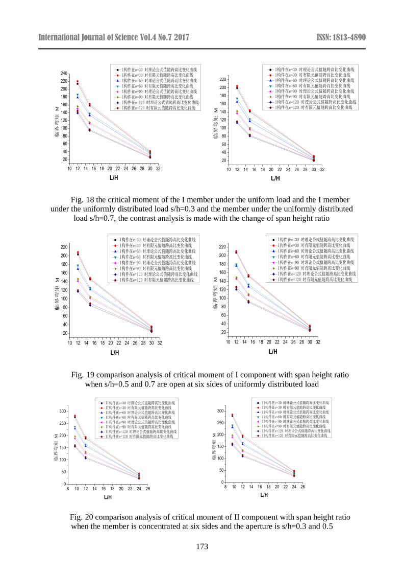
Fig. 18 the critical moment of the I member under the uniform load and the I member under the uniformly distributed load s/h=0.3 and the member under the uniformly distributed
load s/h=0.7, the contrast analysis is made with the change of span height ratio
Fig. 19 comparison analysis of critical moment of I component with span height ratio
when s/h=0.5 and 0.7 are open at six sides of uniformly distributed load
Fig. 20 comparison analysis of critical moment of II component with span height ratio when the member is concentrated at six sides and the aperture is s/h=0.3 and 0.5
10 12 14 16 18 20 22 24 26 28 30 32
20
40
60
80
100
120
140
160
180
200
220
240 I构件在e=30 时理论公式值随跨高比变化曲线 I构件在e=30 时有限元值随跨高比变化曲线 I构件在e=60 时理论公式值随跨高比变化曲线 I构件在e=60 时有限元值随跨高比变化曲线 I构件在e=90 时理论公式值随跨高比变化曲线 I构件在e=90 时有限元值随跨高比变化曲线 I构件在e=120 时理论公式值随跨高比变化曲线 I构件在e=120 时有限元值随跨高比变化曲线
临界
弯矩
M
L/H
10 12 14 16 18 20 22 24 26 28 30 32
20
40
60
80
100
120
140
160
180
200
220
临界弯矩
M
L/H
I构件在e=30 时理论公式值随跨高比变化曲线 I构件在e=30 时有限元值随跨高比变化曲线 I构件在e=60 时理论公式值随跨高比变化曲线 I构件在e=60 时有限元值随跨高比变化曲线 I构件在e=90 时理论公式值随跨高比变化曲线 I构件在e=90 时有限元值随跨高比变化曲线 I构件在e=120 时理论公式值随跨高比变化曲线 I构件在e=120 时有限元值随跨高比变化曲线
10 12 14 16 18 20 22 24 26 28 30 32
20
40
60
80
100
120
140
160
180
200
220
I构件在e=30 时理论公式值随跨高比变化曲线 I构件在e=30 时有限元值随跨高比变化曲线 I构件在e=60 时理论公式值随跨高比变化曲线 I构件在e=60 时有限元值随跨高比变化曲线 I构件在e=90 时理论公式值随跨高比变化曲线 I构件在e=90 时有限元值随跨高比变化曲线 I构件在e=120 时理论公式值随跨高比变化曲线 I构件在e=120 时有限元值随跨高比变化曲线
临界
弯矩
M
L/H
10 12 14 16 18 20 22 24 26 28 30 32
20
40
60
80
100
120
140
160
180
200
220
I构件在e=30 时理论公式值随跨高比变化曲线 I构件在e=30 时有限元值随跨高比变化曲线 I构件在e=60 时理论公式值随跨高比变化曲线 I构件在e=60 时有限元值随跨高比变化曲线 I构件在e=90 时理论公式值随跨高比变化曲线 I构件在e=90 时有限元值随跨高比变化曲线 I构件在e=120 时理论公式值随跨高比变化曲线 I构件在e=120 时有限元值随跨高比变化曲线
临界
弯矩
M
L/H
8 10 12 14 16 18 20 22 24 260
50
100
150
200
250
300
II构件在e=30 时理论公式值随跨高比变化曲线 II构件在e=30 时有限元值随跨高比变化曲线 II构件在e=60 时理论公式值随跨高比变化曲线 II构件在e=60 时有限元值随跨高比变化曲线 II构件在e=90 时理论公式值随跨高比变化曲线 II构件在e=90 时有限元值随跨高比变化曲线 II构件在e=120 时理论公式值随跨高比变化曲线 II构件在e=120 时有限元值随跨高比变化曲线
临界弯矩
M
L/H
8 10 12 14 16 18 20 22 24 260
50
100
150
200
250
300
II构件在e=30 时理论公式值随跨高比变化曲线 II构件在e=30 时有限元值随跨高比变化曲线 II构件在e=60 时理论公式值随跨高比变化曲线 II构件在e=60 时有限元值随跨高比变化曲线 II构件在e=90 时理论公式值随跨高比变化曲线 II构件在e=90 时有限元值随跨高比变化曲线 II构件在e=120 时理论公式值随跨高比变化曲线 II构件在e=120 时有限元值随跨高比变化曲线
临界弯矩
M
L/H
International Journal of Science Vol.4 No.7 2017 ISSN: 1813-4890
174
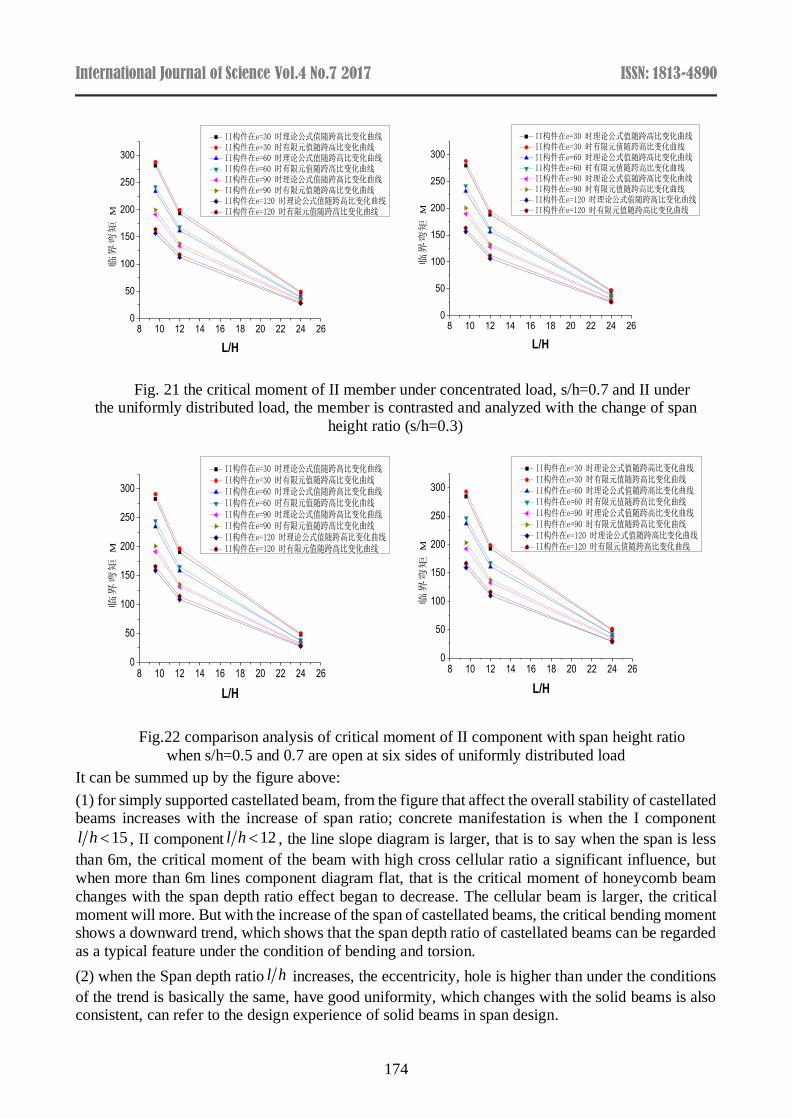
Fig. 21 the critical moment of II member under concentrated load, s/h=0.7 and II under the uniformly distributed load, the member is contrasted and analyzed with the change of span
height ratio (s/h=0.3)
Fig.22 comparison analysis of critical moment of II component with span height ratio
when s/h=0.5 and 0.7 are open at six sides of uniformly distributed load
It can be summed up by the figure above:
(1) for simply supported castellated beam, from the figure that affect the overall stability of castellated beams increases with the increase of span ratio; concrete manifestation is when the I component
15l h , II component 12l h , the line slope diagram is larger, that is to say when the span is less
than 6m, the critical moment of the beam with high cross cellular ratio a significant influence, but
when more than 6m lines component diagram flat, that is the critical moment of honeycomb beam
changes with the span depth ratio effect began to decrease. The cellular beam is larger, the critical
moment will more. But with the increase of the span of castellated beams, the critical bending moment shows a downward trend, which shows that the span depth ratio of castellated beams can be regarded
as a typical feature under the condition of bending and torsion.
(2) when the Span depth ratio l h increases, the eccentricity, hole is higher than under the conditions
of the trend is basically the same, have good uniformity, which changes with the solid beams is also consistent, can refer to the design experience of solid beams in span design.
8 10 12 14 16 18 20 22 24 260
50
100
150
200
250
300
II构件在e=30 时理论公式值随跨高比变化曲线 II构件在e=30 时有限元值随跨高比变化曲线 II构件在e=60 时理论公式值随跨高比变化曲线 II构件在e=60 时有限元值随跨高比变化曲线 II构件在e=90 时理论公式值随跨高比变化曲线 II构件在e=90 时有限元值随跨高比变化曲线 II构件在e=120 时理论公式值随跨高比变化曲线 II构件在e=120 时有限元值随跨高比变化曲线
临界弯矩
M
L/H
8 10 12 14 16 18 20 22 24 260
50
100
150
200
250
300
II构件在e=30 时理论公式值随跨高比变化曲线 II构件在e=30 时有限元值随跨高比变化曲线 II构件在e=60 时理论公式值随跨高比变化曲线 II构件在e=60 时有限元值随跨高比变化曲线 II构件在e=90 时理论公式值随跨高比变化曲线 II构件在e=90 时有限元值随跨高比变化曲线 II构件在e=120 时理论公式值随跨高比变化曲线 II构件在e=120 时有限元值随跨高比变化曲线
临界弯矩
M
L/H
8 10 12 14 16 18 20 22 24 260
50
100
150
200
250
300
II构件在e=30 时理论公式值随跨高比变化曲线 II构件在e=30 时有限元值随跨高比变化曲线 II构件在e=60 时理论公式值随跨高比变化曲线 II构件在e=60 时有限元值随跨高比变化曲线 II构件在e=90 时理论公式值随跨高比变化曲线 II构件在e=90 时有限元值随跨高比变化曲线 II构件在e=120 时理论公式值随跨高比变化曲线 II构件在e=120 时有限元值随跨高比变化曲线
临界弯矩
M
L/H
8 10 12 14 16 18 20 22 24 260
50
100
150
200
250
300
II构件在e=30 时理论公式值随跨高比变化曲线 II构件在e=30 时有限元值随跨高比变化曲线 II构件在e=60 时理论公式值随跨高比变化曲线 II构件在e=60 时有限元值随跨高比变化曲线 II构件在e=90 时理论公式值随跨高比变化曲线 II构件在e=90 时有限元值随跨高比变化曲线 II构件在e=120 时理论公式值随跨高比变化曲线 II构件在e=120 时有限元值随跨高比变化曲线
临界弯矩
M
L/H
International Journal of Science Vol.4 No.7 2017 ISSN: 1813-4890
175
(3) comparative analysis of I component and II component, in the span l and eccentricity e under the
same conditions, the critical moment of growth with the increase of the compression flange width,
And decrease with the increase of eccentricity, change rate is quite obvious, but the trend is consistent
with the trend of solid web beam so, increasing the compression flange width can significantly improve the overall stability of steel beam bearing capacity limit.
(4) when the span is smaller, the slope of the critical moment varies with the eccentricity, which
shows that the ultimate load decreases with the increase of the eccentricity. The larger the span is,
the smaller the slope of the critical moment varies with the eccentricity, and the trend of the ultimate
load tends to decrease with the increase of the eccentricity. In the same section and eccentricity under certain circumstances, the critical moment decreases with the increase of the span, with the span
increasing, the critical moment of the curve slope of castellated beam with the span of change is small,
and this trend tends to slow the known solid beams change trend is consistent, suggesting a correlation.
4. Summary
(1) using ABAQUS finite element software to simulate the castellated beam, simulate the flexural
and torsional buckling of the hexagon and round castellated beam of simply supported castellated
beam under the bending and torsion state, and obtain the corresponding critical moment load.
(2) the overall stability of castellated beam is analyzed with the change of eccentricity and span. It is found that the critical moment of the castellated beam is closer to the critical moment of the spandrel
beam when the increase is increased. The critical moment of comparison of honeycomb beam critical
moment and solid beam, found that the bearing capacity of the bearing capacity and solid beams vary
in a certain range, the eccentricity, the size of the hole and the two span of the honeycomb beam in
bending and torsion conditions affect the overall stability when mutual restriction. It also provides
reference for the practical design of castellated beams.
References
[1] National Standard of People's Republic of China. Code for design of steel structures (GB50017-
2003) [S]. Beijing: China Planning Press, 2003, 22-25
[2] People's Republic of China national standard. Technical specification for cold-formed thin-
walled steel structures (GB50018-2002) [S]. Beijing: China Planning Press, 2002, 21-30
[3] Chen Shaofan. Guide to the stability design of steel structures. [M]., Second ed. Beijing: China
Construction Industry Press, 2004:95-98
[4] Chen Ji. The Theory and Design of Steel Structure Stability, Sixth Edition [M]. Beijing: Science
Press, 2014 [5] Yang Yinghua, Zhang Mi. Stability Checking of Steel Beams Under Biaxial Bending And
Torsion [J]. steel structure, 2008, 23 (5): 7-10
[6] Wang Xuefei, Wang Tiehong. Discussion On The Design Method of Steel Beam Torsion [J].
chemical engineering, 2009, 19 (3): 43-47
[7] Penley. Study on the overall stability of I-shaped steel beams under combined bending and
torsion [D]. Changsha: Hunan University, 2010, 18-21, 33-58
[8] Li Pengfei, Yao Qianfeng, Guo Meng. Analysis of Flexural Torsional Buckling of Castellated
Beam And Calculation of Its Overall Stability [J]. Beijing: Journal of Beijing Jiaotong University,
2010,
[9] Hu Hu. Study on overall stability of I-shaped section steel beam under combined bending and
torsion [D]. Changsha: Hunan University, 2011, 24-27, 53-57 [10] Chen Caihong. Study on the overall stability of single axis symmetrical I-beam under combined
bending and torsion [D]. Changsha: Hunan University, 2013, 11-14,
[11] Wang Yuzhuo, Fu Cheng,.ABAQUS. Structural Engineering Analysis And Detailed Examples.
[M]. Chinese architecture and Building Press, 2013, 1-83
[12] Xu Bingye, Liu Xinsheng. Applied Elastoplastic Mechanics [M]. Beijing: Tsinghua University
press, 2003,92-125
International Journal of Science Vol.4 No.7 2017 ISSN: 1813-4890
176
[13] Wang Jinchang, Yekai Chen. ABAQUS in civil engineering[M]. Hangzhou: Zhejiang University
press, 2006, 1-40
[14] Zhuang Zhuo. ABAQUS nonlinear finite element analysis [M]. Beijing: Science Press, 2005, 1-
30