Embed Size (px)
Citation preview
Analysis of Trailer Position Error in an AutonomousRobot-Trailer System With Sensor Noise
David W. Hodo!, John Y. Hung!, David M. Bevly†, and D. Scott Millhouse‡
!Electrical & Computer Engineering Dept.Auburn University, AL 36849
Email: [email protected], [email protected]
†Mechanical Engineering Dept.Auburn University, AL 36849Email: [email protected]
‡U.S. Army Corps of EngineersEngineering & Support Center - Huntsville
Huntsville, AL 35807-4301
Abstract—A low cost solution for controlling trailer lateralposition in a robotic tractor-trailer system is being considered. Inthis paper, several practical issues involved in the implementationof such a system are presented. Instruments for navigation andcontrol consist of a single GPS receiver and a hitch-mountedsensor for the measurement of the angle between robot (tractor)and trailer. In previous work, the authors examined the effectsof errors in the hitch-angle measurement on path trackingperformance. This analysis will now be expanded to include theeffects of noise in the GPS measurements. The relative merits ofmounting the GPS receiver on the robot or trailer are considered.
I. INTRODUCTION
In this paper, a low cost solution for precise path followingof a robotic tractor-trailer system is being considered. Controlof mobile robots, including mobile robots pulling trailers, hasbeen the subject of much research. Several different controlmethods have been developed for such systems. A goodoverview of these methods can be found in [1]. These systemshave many practical uses including factory automation as wellas agricultural and military applications.
II. BACKGROUND
A robotic tractor-trailer system is currently being developedat Auburn University in conjunction with the U.S. Army Corpsof Engineers and the Environmental Security TechnologyCertification Program (ESTCP) for the purpose of locatingand mapping unexploded ordnance (UXO) for humanitarianbenefit. Currently various types of magnetometers and elec-tromagnetic sensors are towed by either a human or all-terain vehicle (ATV) for geophysical mapping of an area. Itis proposed that safety, precision, and efficiency can all beimproved by replacing the current methods with a low cost,portable, highly accurate robotic system. In order to accuratelymap buried UXO, precise positioning of the sensors as wellas high repeatability between runs is necessary.
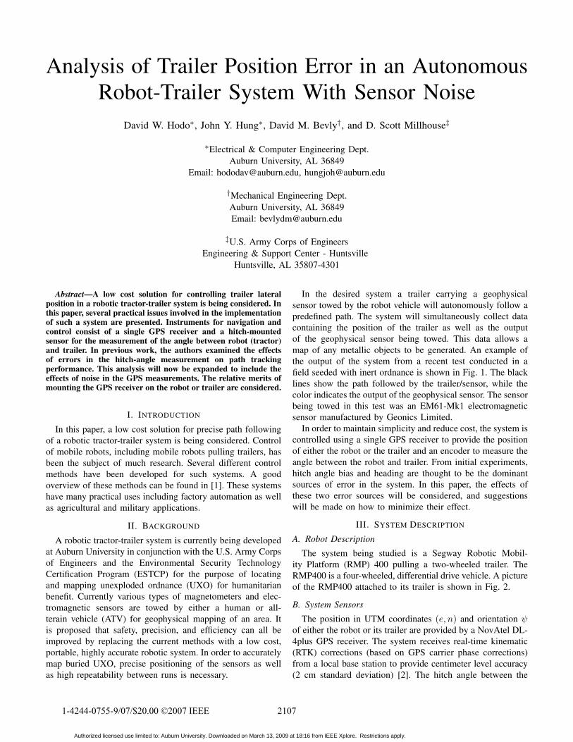
In the desired system a trailer carrying a geophysicalsensor towed by the robot vehicle will autonomously follow apredefined path. The system will simultaneously collect datacontaining the position of the trailer as well as the outputof the geophysical sensor being towed. This data allows amap of any metallic objects to be generated. An example ofthe output of the system from a recent test conducted in afield seeded with inert ordnance is shown in Fig. 1. The blacklines show the path followed by the trailer/sensor, while thecolor indicates the output of the geophysical sensor. The sensorbeing towed in this test was an EM61-Mk1 electromagneticsensor manufactured by Geonics Limited.
In order to maintain simplicity and reduce cost, the system iscontrolled using a single GPS receiver to provide the positionof either the robot or the trailer and an encoder to measure theangle between the robot and trailer. From initial experiments,hitch angle bias and heading are thought to be the dominantsources of error in the system. In this paper, the effects ofthese two error sources will be considered, and suggestionswill be made on how to minimize their effect.
III. SYSTEM DESCRIPTION
A. Robot DescriptionThe system being studied is a Segway Robotic Mobil-
ity Platform (RMP) 400 pulling a two-wheeled trailer. TheRMP400 is a four-wheeled, differential drive vehicle. A pictureof the RMP400 attached to its trailer is shown in Fig. 2.
B. System SensorsThe position in UTM coordinates (e, n) and orientation !
of either the robot or its trailer are provided by a NovAtel DL-4plus GPS receiver. The system receives real-time kinematic(RTK) corrections (based on GPS carrier phase corrections)from a local base station to provide centimeter level accuracy(2 cm standard deviation) [2]. The hitch angle between the
21071-4244-0755-9/07/$20.00 '2007 IEEE
Authorized licensed use limited to: Auburn University. Downloaded on March 13, 2009 at 18:16 from IEEE Xplore. Restrictions apply.
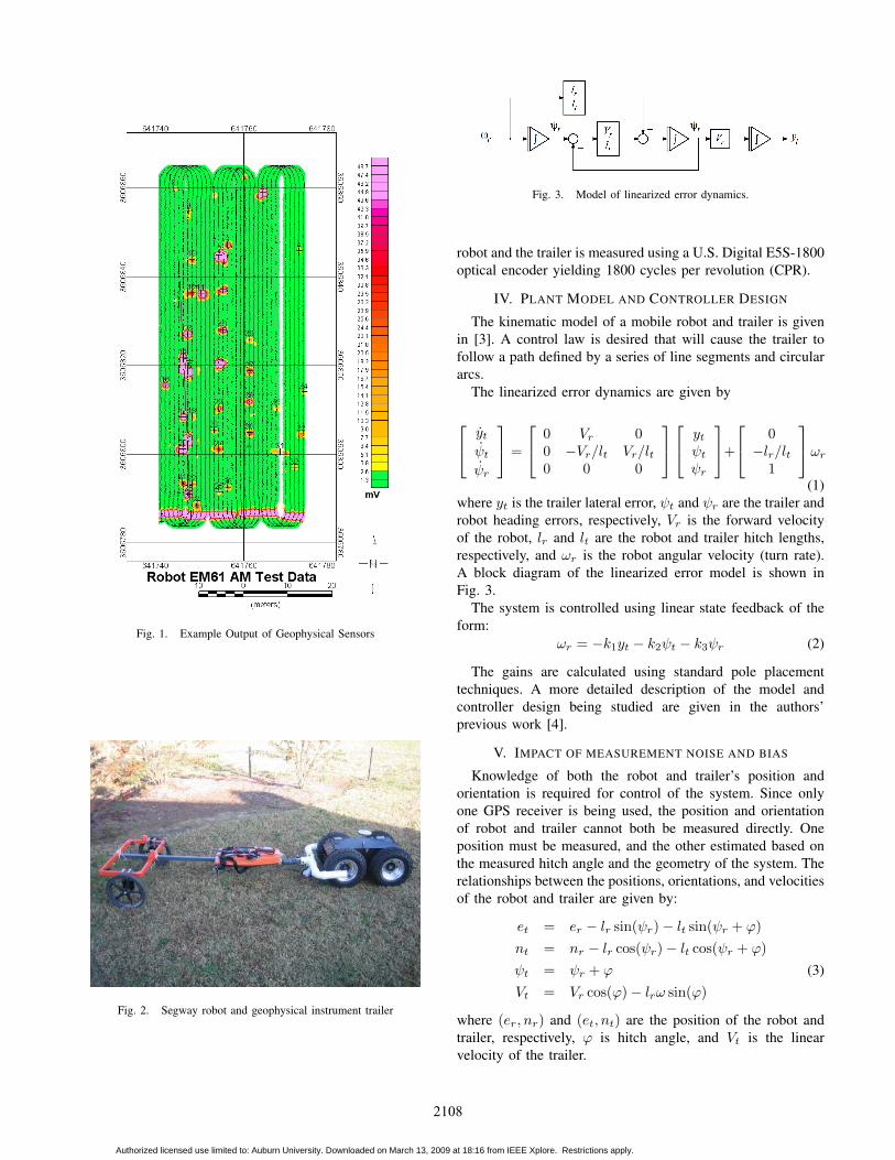
Fig. 1. Example Output of Geophysical Sensors
Fig. 2. Segway robot and geophysical instrument trailer
Fig. 3. Model of linearized error dynamics.
robot and the trailer is measured using a U.S. Digital E5S-1800optical encoder yielding 1800 cycles per revolution (CPR).
IV. PLANT MODEL AND CONTROLLER DESIGN
The kinematic model of a mobile robot and trailer is givenin [3]. A control law is desired that will cause the trailer tofollow a path defined by a series of line segments and circulararcs.
The linearized error dynamics are given by
!
"yt
!t
!r
#
$ =
!
"0 Vr 00 !Vr/lt Vr/lt0 0 0
#
$
!
"yt
!t
!r
#
$+
!
"0
!lr/lt1
#
$"r
(1)where yt is the trailer lateral error, !t and !r are the trailer androbot heading errors, respectively, Vr is the forward velocityof the robot, lr and lt are the robot and trailer hitch lengths,respectively, and "r is the robot angular velocity (turn rate).A block diagram of the linearized error model is shown inFig. 3.
The system is controlled using linear state feedback of theform:
"r = !k1yt ! k2!t ! k3!r (2)
The gains are calculated using standard pole placementtechniques. A more detailed description of the model andcontroller design being studied are given in the authors’previous work [4].
V. IMPACT OF MEASUREMENT NOISE AND BIAS
Knowledge of both the robot and trailer’s position andorientation is required for control of the system. Since onlyone GPS receiver is being used, the position and orientationof robot and trailer cannot both be measured directly. Oneposition must be measured, and the other estimated based onthe measured hitch angle and the geometry of the system. Therelationships between the positions, orientations, and velocitiesof the robot and trailer are given by:
et = er ! lr sin(!r)! lt sin(!r + #)nt = nr ! lr cos(!r)! lt cos(!r + #)!t = !r + # (3)Vt = Vr cos(#)! lr" sin(#)
where (er, nr) and (et, nt) are the position of the robot andtrailer, respectively, # is hitch angle, and Vt is the linearvelocity of the trailer.
2108
Authorized licensed use limited to: Auburn University. Downloaded on March 13, 2009 at 18:16 from IEEE Xplore. Restrictions apply.
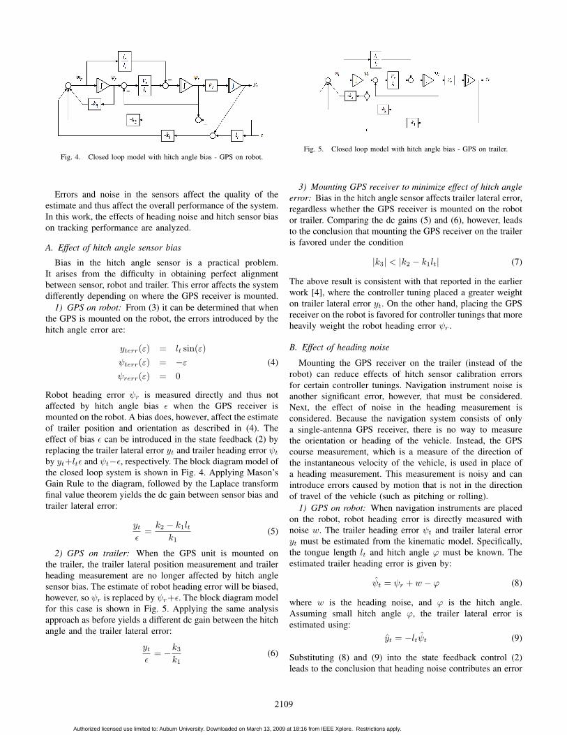
Fig. 4. Closed loop model with hitch angle bias - GPS on robot.
Errors and noise in the sensors affect the quality of theestimate and thus affect the overall performance of the system.In this work, the effects of heading noise and hitch sensor biason tracking performance are analyzed.
A. Effect of hitch angle sensor bias
Bias in the hitch angle sensor is a practical problem.It arises from the difficulty in obtaining perfect alignmentbetween sensor, robot and trailer. This error affects the systemdifferently depending on where the GPS receiver is mounted.
1) GPS on robot: From (3) it can be determined that whenthe GPS is mounted on the robot, the errors introduced by thehitch angle error are:
yterr($) = lt sin($)!terr($) = !$ (4)!rerr($) = 0
Robot heading error !r is measured directly and thus notaffected by hitch angle bias % when the GPS receiver ismounted on the robot. A bias does, however, affect the estimateof trailer position and orientation as described in (4). Theeffect of bias % can be introduced in the state feedback (2) byreplacing the trailer lateral error yt and trailer heading error !t
by yt+lt% and !t!%, respectively. The block diagram model ofthe closed loop system is shown in Fig. 4. Applying Mason’sGain Rule to the diagram, followed by the Laplace transformfinal value theorem yields the dc gain between sensor bias andtrailer lateral error:
yt
%=
k2 ! k1ltk1
(5)
2) GPS on trailer: When the GPS unit is mounted onthe trailer, the trailer lateral position measurement and trailerheading measurement are no longer affected by hitch anglesensor bias. The estimate of robot heading error will be biased,however, so !r is replaced by !r+%. The block diagram modelfor this case is shown in Fig. 5. Applying the same analysisapproach as before yields a different dc gain between the hitchangle and the trailer lateral error:
yt
%= !k3
k1(6)
Fig. 5. Closed loop model with hitch angle bias - GPS on trailer.
3) Mounting GPS receiver to minimize effect of hitch angleerror: Bias in the hitch angle sensor affects trailer lateral error,regardless whether the GPS receiver is mounted on the robotor trailer. Comparing the dc gains (5) and (6), however, leadsto the conclusion that mounting the GPS receiver on the traileris favored under the condition
|k3| < |k2 ! k1lt| (7)
The above result is consistent with that reported in the earlierwork [4], where the controller tuning placed a greater weighton trailer lateral error yt. On the other hand, placing the GPSreceiver on the robot is favored for controller tunings that moreheavily weight the robot heading error !r.
B. Effect of heading noise
Mounting the GPS receiver on the trailer (instead of therobot) can reduce effects of hitch sensor calibration errorsfor certain controller tunings. Navigation instrument noise isanother significant error, however, that must be considered.Next, the effect of noise in the heading measurement isconsidered. Because the navigation system consists of onlya single-antenna GPS receiver, there is no way to measurethe orientation or heading of the vehicle. Instead, the GPScourse measurement, which is a measure of the direction ofthe instantaneous velocity of the vehicle, is used in place ofa heading measurement. This measurement is noisy and canintroduce errors caused by motion that is not in the directionof travel of the vehicle (such as pitching or rolling).
1) GPS on robot: When navigation instruments are placedon the robot, robot heading error is directly measured withnoise w. The trailer heading error !t and trailer lateral erroryt must be estimated from the kinematic model. Specifically,the tongue length lt and hitch angle # must be known. Theestimated trailer heading error is given by:
!t = !r + w ! # (8)
where w is the heading noise, and # is the hitch angle.Assuming small hitch angle #, the trailer lateral error isestimated using:
yt = !lt!t (9)
Substituting (8) and (9) into the state feedback control (2)leads to the conclusion that heading noise contributes an error
2109
Authorized licensed use limited to: Auburn University. Downloaded on March 13, 2009 at 18:16 from IEEE Xplore. Restrictions apply.
to the controller output "r, and the gain Nr on the headingnoise is of the form
Nr = k2 + k3 ! k1lt (10)
2) GPS on the trailer: With navigation instruments on thetrailer, both the trailer heading error and trailer lateral positionare measured directly. Robot heading error must be estimatedfrom the relationship:
!r = !t + w + # (11)
In this case, the gain Nt on the heading noise is of the form
Nt = k2 + k3 (12)
3) Mounting GPS receiver to minimize effects of headingnoise: Comparing (10) and (12) leads to the the conclusionthat it is preferable to mount the GPS receiver on the robotfor controller tunings where
|Nr| < |Nt||k2 + k3 ! k1lt| " |k2 + k3| (13)
VI. VALIDATION
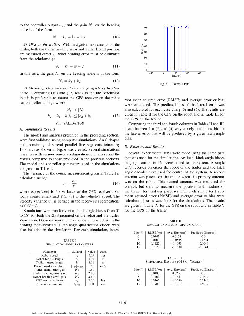
A. Simulation ResultsThe model and analysis presented in the preceding sections
were first validated using computer simulations. An S-shapedpath consisting of several parallel line segments joined by180! arcs as shown in Fig. 6 was created. Several simulationswere run with various sensor configurations and errors and theresults compared to those predicted in the previous sections.The model and controller parameters used in the simulationsare given in Table I.
The variance of the course measurement given in Table I iscalculated using:
&c =&v
V(14)
where &v(m/sec) is the variance of the GPS receiver’s ve-locity measurement and V (m/s) is the vehicle’s speed. Thevelocity variance &v is defined in the receiver’s specificationsas 0.03m/s.
Simulations were run for various hitch angle biases from 0!to 15! for both the GPS mounted on the robot and the trailer.Zero mean, Gaussian noise with variance &c was added to theheading measurements. Hitch angle quantization effects werealso included in the simulation. For each simulation, lateral
TABLE ISIMULATION MODEL PARAMETERS
Parameter Symbol Value UnitsRobot speed Vr 0.75 m/s
Robot tongue length lr 0.95 mTrailer tongue length lt 2.11 m
Robot angular rate limit |!r|max 3 rad/sTrailer lateral error gain K1 1.89
Trailer heading error gain K2 2.86Robot heading error gain K3 3.62
GPS course variance "c 2.29 deg.Simulation duration tsim 200 sec.
−20 0 20 40 600
10
20
30
40
50
60
70
East (m)
North
(m)
Fig. 6. Example Path
root mean squared error (RMSE) and average error or biaswere calculated. The predicted bias of the lateral error wasalso calculated for each case using (5) and (6). The results aregiven in Table II for the GPS on the robot and in Table III forthe GPS on the trailer.
Comparing the third and fourth columns in Tables II and III,it can be seen that (5) and (6) very closely predict the bias inthe lateral error that will be produced by a given hitch anglebias.
B. Experimental Results
Several experimental runs were made using the same paththat was used for the simulations. Artificial hitch angle biasesranging from 0! to 15! were added to the system. A singleGPS receiver on either the robot or the trailer and the hitchangle encoder were used for control of the system. A secondantenna was placed on the trailer when the primary antennawas on the robot. This second antenna was not used forcontrol, but only to measure the position and heading ofthe trailer for analysis purposes. For each run, lateral rootmean squared error (RMSE) and average error or bias werecalculated, just as was done for the simulations. The resultsare given in Table IV for the GPS on the robot and in Table Vfor the GPS on the trailer.
TABLE IISIMULATION RESULTS (GPS ON ROBOT)
Bias(!) RMSE(m) Avg. Error(m) Predicted Bias(m)0 0.0447 0.0138 0.05 0.0700 -0.0595 -0.052110 0.1122 -0.1053 -0.104015 0.1578 -0.1508 -0.1561
TABLE IIISIMULATION RESULTS (GPS ON TRAILER)
Bias(!) RMSE(m) Avg. Error(m) Predicted Bias(m)0 0.0480 0.0216 0.05 0.1709 -0.1641 -0.167410 0.3362 -0.3296 -0.334415 0.4988 -0.4917 -0.5019
2110
Authorized licensed use limited to: Auburn University. Downloaded on March 13, 2009 at 18:16 from IEEE Xplore. Restrictions apply.
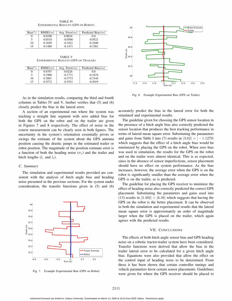
TABLE IVEXPERIMENTAL RESULTS (GPS ON ROBOT)
Bias(!) RMSE(m) Avg. Error(m) Predicted Bias(m)0 0.0100 0.0034 0.05 0.0510 -0.0500 -0.052110 0.1030 -0.1021 -0.104015 0.1480 -0.1471 -0.1561
TABLE VEXPERIMENTAL RESULTS (GPS ON TRAILER)
Bias(!) RMSE(m) Avg. Error(m) Predicted Bias(m)0 0.0707 0.0226 0.05 0.1900 -0.1771 -0.167410 0.3801 -0.3772 -0.334415 0.5572 -0.5551 -0.5019
As in the simulation results, comparing the third and fourthcolumns in Tables IV and V, further verifies that (5) and (6)closely predict the bias in the lateral error.
A section of an experimental run where the system wastracking a straight line segment with zero added bias forboth the GPS on the robot and on the trailer are givenin Figures 7 and 8 respectively. The effect of noise in thecourse measurement can be clearly seen in both figures. Theuncertainty in the system’s orientation essentially pivots orswings the estimate of the system about the GPS antennaposition causing the drastic jumps in the estimated trailer orrobot position. The magnitude of the position estimate error isa function of both the heading noise (&c) and the trailer andhitch lengths (lr and lt).
C. Summary
The simulation and experimental results provided are con-sistent with the analysis of hitch angle bias and headingnoise presented in the previous sections. For the system underconsideration, the transfer functions given in (5) and (6)
−0.6 −0.4 −0.2 0 0.2 0.4
39.2
39.3
39.4
39.5
39.6
39.7
39.8
39.9
40
East (m)
Nor
th (m
)
Trailer EstimateRobot
Fig. 7. Example Experimental Run (GPS on Robot)
11.4 11.6 11.8 12 12.2 12.4 12.6 12.8
49
49.2
49.4
49.6
49.8
50
East (m)
Nor
th (m
)
Robot EstimateTrailer
Fig. 8. Example Experimental Run (GPS on Trailer)
accurately predict the bias in the lateral error for both thesimulated and experimental results.
The guideline given for choosing the GPS sensor location inthe presence of a hitch angle bias also correctly predicted thesensor location that produces the best tracking performance interms of lateral mean square error. Substituting the parametersand gains from Table I into (7) results in |3.62| > |! 1.1279|which suggests that the effect of a hitch angle bias would beminimized by placing the GPS on the robot. When zero biaswas used in simulation, the results for the GPS on the robotand on the trailer were almost identical. This is as expected,since in the absence of sensor imperfections, sensor placementshould have no effect on system performance. As the biasincreases, however, the average error when the GPS is on therobot is significantly smaller than the average error when theGPS is on the trailer, as is predicted.
The guideline for placing the GPS receiver to minimize theeffect of heading noise also correctly predicted the correct GPSplacement. Substituting the parameters and gains used into(13) results in |2.492| < |6.48| which suggests that having theGPS on the robot is the better placement. It can be observedin both the simulation and experimental results that the lateralmean square error is approximately an order of magnitudelarger when the GPS is placed on the trailer, which againagrees with the predicted results.
VII. CONCLUSIONS
The effects of both hitch angle sensor bias and GPS headingnoise on a robotic tractor-trailer system have been considered.Transfer functions were derived that allow the bias in thetrailer lateral error to be calculated for a given hitch anglebias. Equations were also provided that allow the effect onthe control input of heading noise to be determined. Fromthese it has been shown that certain controller tunings andvehicle parameters favor certain sensor placements. Guidelineswere given for where the GPS receiver should be placed to
2111
Authorized licensed use limited to: Auburn University. Downloaded on March 13, 2009 at 18:16 from IEEE Xplore. Restrictions apply.
minimize the effects of these errors based on those parametersand tunings.
The authors have shown that when implementing a robotictractor-trailer system, measurement imperfections can have asignificant impact on control system performance and shouldbe taken into account. The analysis given can help to predictthe effect various measurement errors will have on the systemand suggest a sensor placement to minimize their effects.
VIII. ACKNOWLEDGEMENTS
The authors express thanks for the support of the U.S.Army Corps of Engineers and the Environmental SecurityTechnology Certification Program (ESTCP).
REFERENCES
[1] S. De Luca, Oriolo, Robot Motion Planning and Control. Spring, 1998,ch. Feedback Control of a Nonholonomic Car-like Robot, pp. 343–427.
[2] J. J. Spilker, Jr., “Fundamentals of signal tracking theory,” in GlobalPositioning System: Theory and Applications, Volume 1, ser. Progress inAstronautics and Aeronautics, B. W. Parkinson, Ed. Washington, DC:American Institute of Aeronautics and Astronautics, 1996, vol. 163, ch. 4.
[3] F. Lamiraux, S. Sekhavat, and J. Laumond, “Motion planning andcontrol for hilare pulling a trailer,” IEEE Transactions on Robotics andAutomation, vol. 15, no. 4, pp. 640–652, August 1999.
[4] D. W. Hodo, J. Y. Hung, D. M. Bevly, and S. D. Millhouse, “Effects ofsensor placement and errors on path following control of a mobile robot-trailer system,” in Proceedings of American Control Conference. NewYork, NY: American Automatic Control Council, July 2007.
2112
Authorized licensed use limited to: Auburn University. Downloaded on March 13, 2009 at 18:16 from IEEE Xplore. Restrictions apply.