Embed Size (px)
Citation preview
Analysis of Statically Indeterminate Structures
Force Method of Analysis
Chapter 10
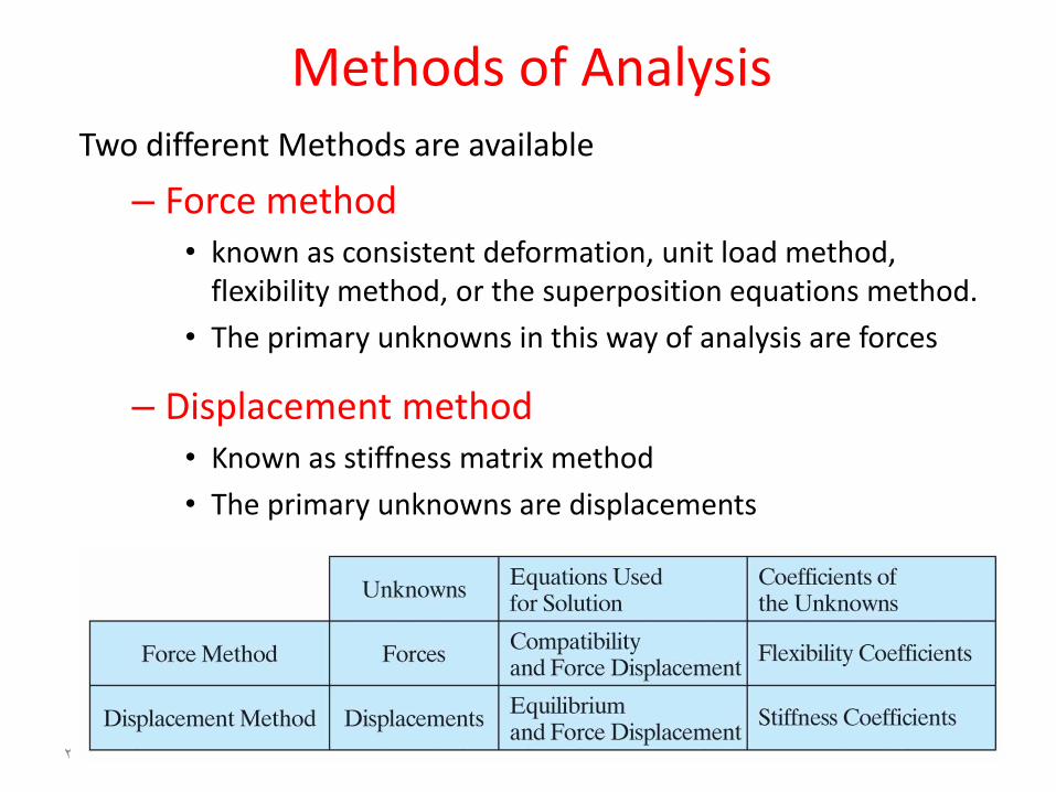
Methods of AnalysisTwo different Methods are available
– Force method • known as consistent deformation, unit load method,
flexibility method, or the superposition equations method.
• The primary unknowns in this way of analysis are forces
– Displacement method• Known as stiffness matrix method
• The primary unknowns are displacements
2
Methods of Analysis
Force method of analysisThe deflection or slope at any point on a structure as a result
of a number of forces, including the reactions, is equal to the algebraic sum of the deflections or slopes at this particular point as a result of these loads acting individually
3
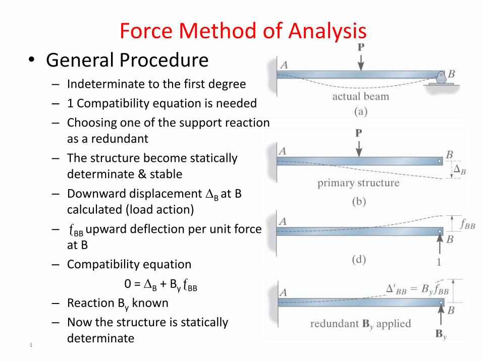
Force Method of Analysis• General Procedure
– Indeterminate to the first degree
– 1 Compatibility equation is needed
– Choosing one of the support reaction as a redundant
– The structure become statically determinate & stable
– Downward displacement B at B calculated (load action)
– BB upward deflection per unit force at B
– Compatibility equation
0 = B + ByBB
– Reaction By known
– Now the structure is statically determinate
4
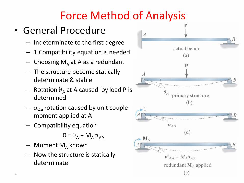
Force Method of Analysis• General Procedure
– Indeterminate to the first degree
– 1 Compatibility equation is needed
– Choosing MA at A as a redundant
– The structure become statically determinate & stable
– Rotation A at A caused by load P is determined
– AA rotation caused by unit couple moment applied at A
– Compatibility equation
0 = A + MA AA
– Moment MA known
– Now the structure is statically determinate
5
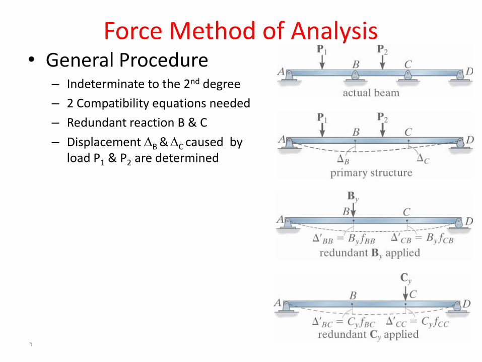
Force Method of Analysis• General Procedure
– Indeterminate to the 2nd degree
– 2 Compatibility equations needed
– Redundant reaction B & C
– Displacement B &C caused by load P1 & P2 are determined
6
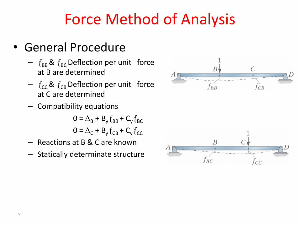
Force Method of Analysis
• General Procedure – BB & BC Deflection per unit force
at B are determined
– CC & CB Deflection per unit force at C are determined
– Compatibility equations
0 = B + ByBB + CyBC
0 = C + ByCB + CyCC
– Reactions at B & C are known
– Statically determinate structure
7
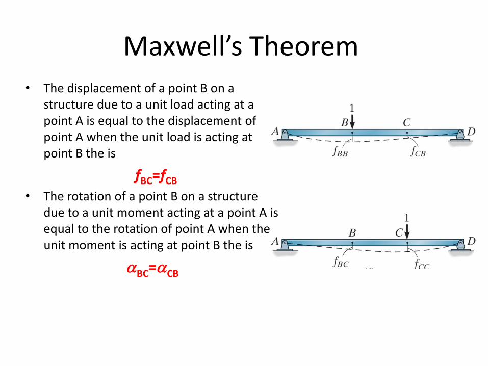
Maxwell’s Theorem • The displacement of a point B on a
structure due to a unit load acting at a point A is equal to the displacement of point A when the unit load is acting at point B the is
fBC=fCB
• The rotation of a point B on a structure due to a unit moment acting at a point A is equal to the rotation of point A when the unit moment is acting at point B the is
BC=CB
Force Method of Analysis• Procedure for Analysis
– Determine the degree of statically indeterminacy
– Identify the redundants, whether it’s a force or a moment, that would be treated as unknown in order to form the structure statically determinate & stable
– Calculate the displacements of the determinate structure at the points where the redundants have been removed
– Calculate the displacements at these same points in the determinate structure due to the unit force or moment of each redundants individually
– Workout the compatibility equation at each point where there is a redundant & solve for the unknown redundants
– Knowing the value of the redundants, use equilibrium to determine the remaining reactions
9
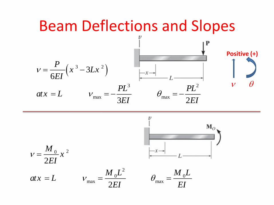
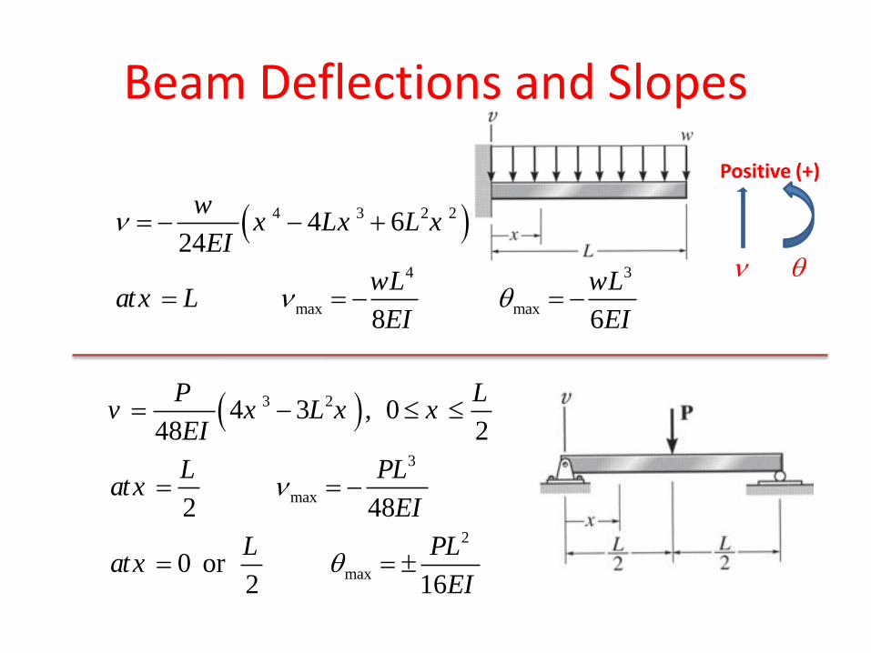
Beam Deflections and Slopes
3 2
3 2
max max
36
3 2
Px Lx
EI
PL PLatx L
EI EI
20
2
0 0max max
2
2
Mx
EI
M L M Latx L
EI EI
Positive (+)
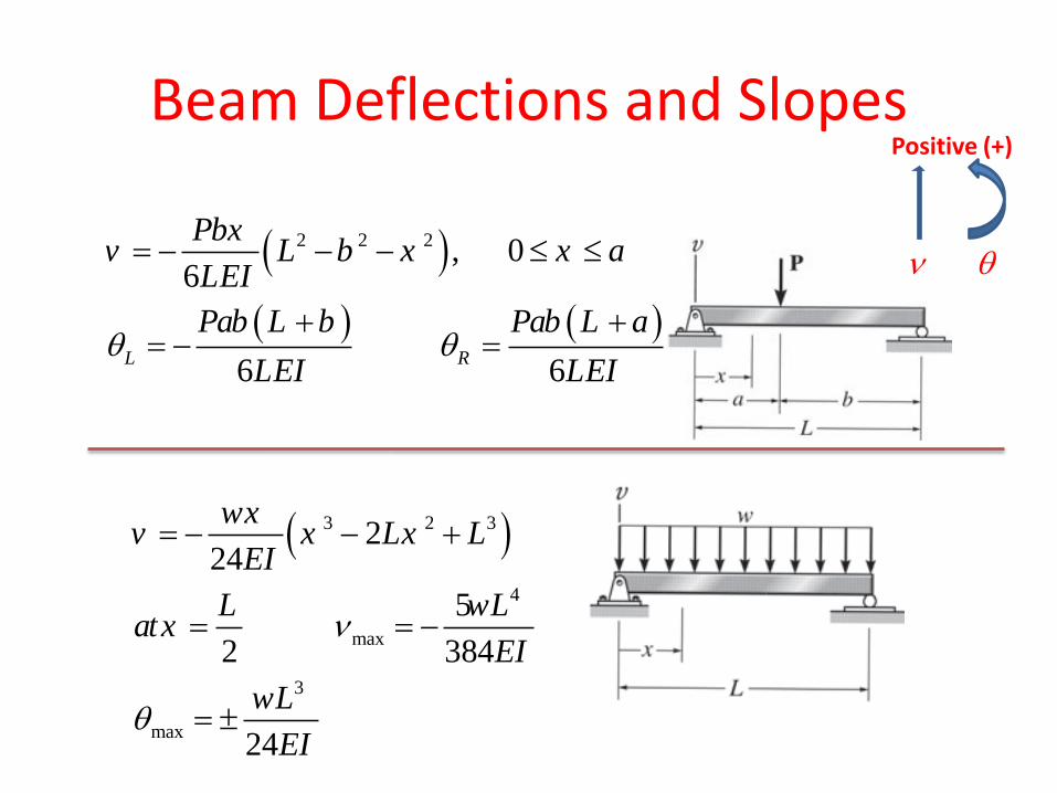
Beam Deflections and Slopes
4 3 2 2
4 3
max max
4 624
8 6
wx Lx L x
EI
wL wLatx L
EI EI
3 2
3
max
2
max
4 3 , 048 2
2 48
0 or 2 16
P Lv x L x x
EI
L PLatx
EI
L PLatx
EI
Positive (+)
Beam Deflections and Slopes
3 2 3
4
max
3
max
224
5
2 384
24
wxv x Lx L
EI
L wLatx
EI
wL
EI
2 2 2 , 06
6 6L R
Pbxv L b x x a
LEI
Pab L b Pab L a
LEI LEI
Positive (+)
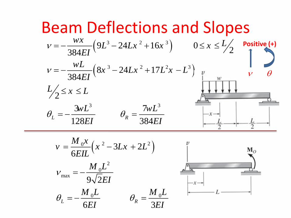
Beam Deflections and Slopes
3 2 3
3 2 2 3
3 3
9 24 16 02384
8 24 17384
2
3 7
128 384L R
wx LL Lx x xEI
wLx Lx L x L
EI
L x L
wL wL
EI EI
2 20
2
0max
0 0
3 26
9 2
6 3L R
M xv x Lx L
EIL
M L
EI
M L M L
EI EI
Positive (+)
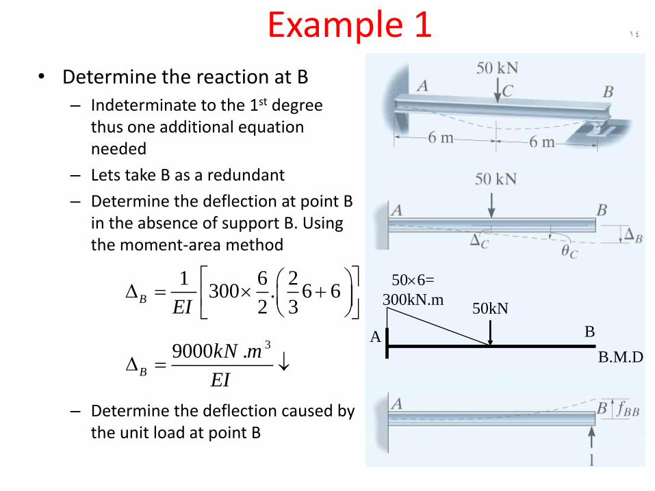
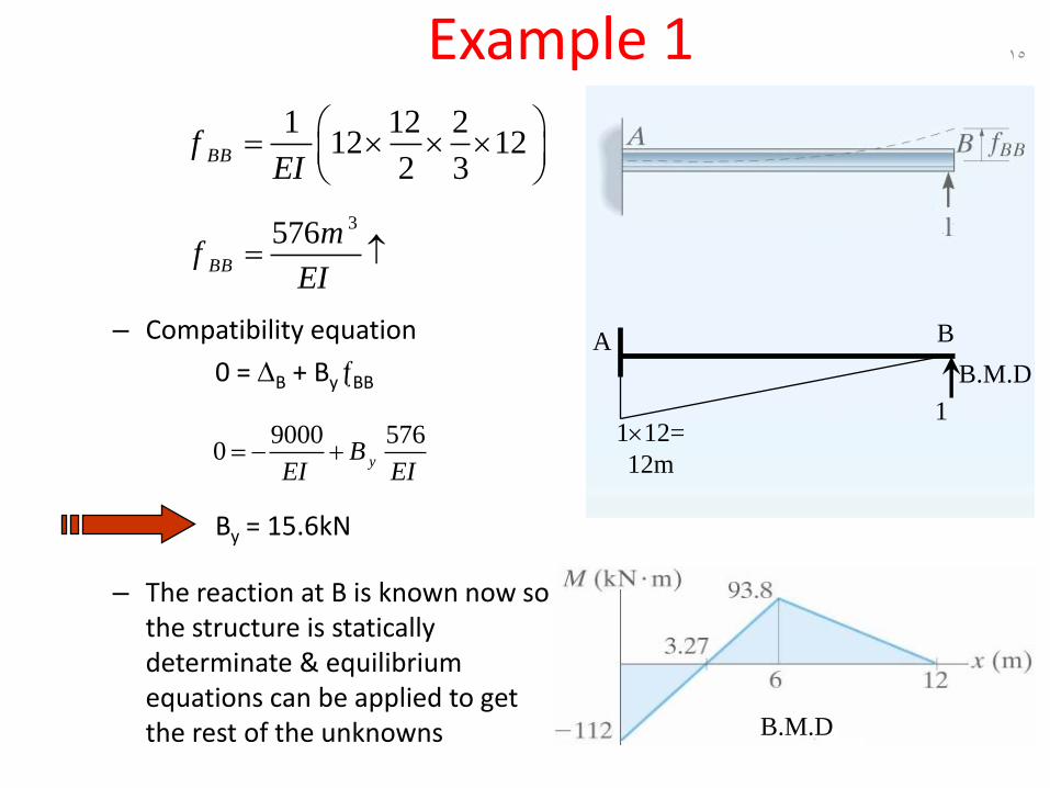
Example 1• Determine the reaction at B
– Indeterminate to the 1st degree thus one additional equation needed
– Lets take B as a redundant
– Determine the deflection at point B in the absence of support B. Using the moment-area method
– Determine the deflection caused by the unit load at point B
39000 .B
kN m
EI
14
506=
300kN.m
B.M.D
BA
50kN
1 6 2300 . 6 6
2 3B
EI
Example 1
– Compatibility equation
0 = B + ByBB
By = 15.6kN
– The reaction at B is known now so the structure is statically determinate & equilibrium equations can be applied to get the rest of the unknowns
3576BB
mf
EI
15
1 12 212 12
2 3BBf
EI
112=
12m
B.M.D
BA
19000 576
0 yBEI EI
B.M.D
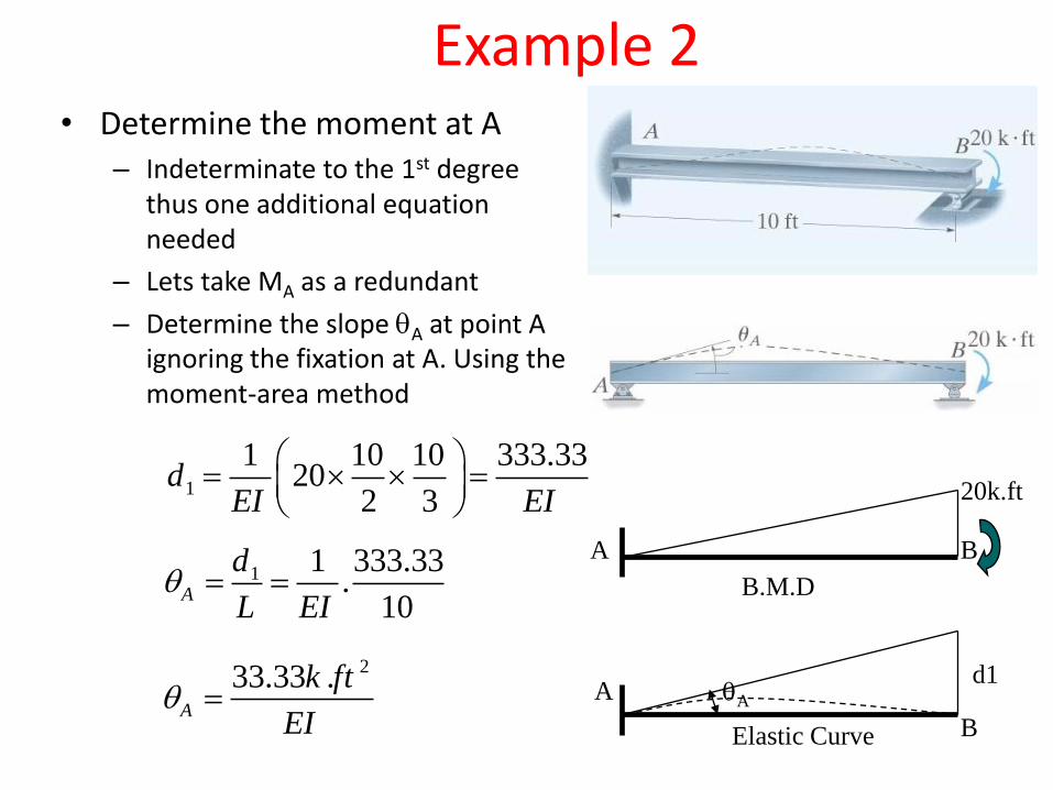
Example 2• Determine the moment at A
– Indeterminate to the 1st degree thus one additional equation needed
– Lets take MA as a redundant
– Determine the slope A at point A ignoring the fixation at A. Using the moment-area method
1
1 10 10 333.3320
2 3d
EI EI
A
20k.ft
B.M.D
B1 1 333.33
.10
A
d
L EI
233.33 .A
k ft
EI
B
A A
d1
Elastic Curve
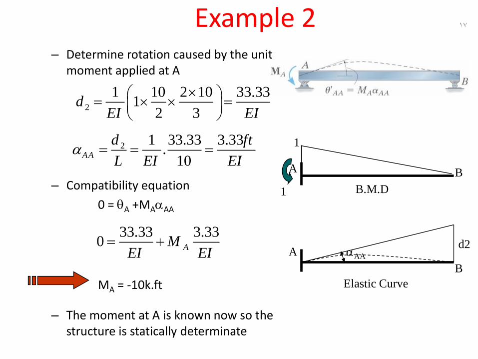
Example 2– Determine rotation caused by the unit
moment applied at A
– Compatibility equation
0 = A +MAAA
MA = -10k.ft
– The moment at A is known now so the structure is statically determinate
2
1 10 2 10 33.331
2 3d
EI EI
17
33.33 3.330 AM
EI EI
B
A AA
d2
Elastic Curve
1 B.M.D
BA
12 1 33.33 3.33.
10AA
d ft
L EI EI
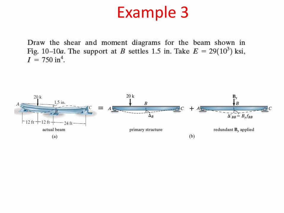
Example 3
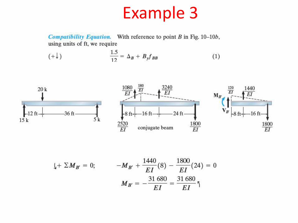
Example 3
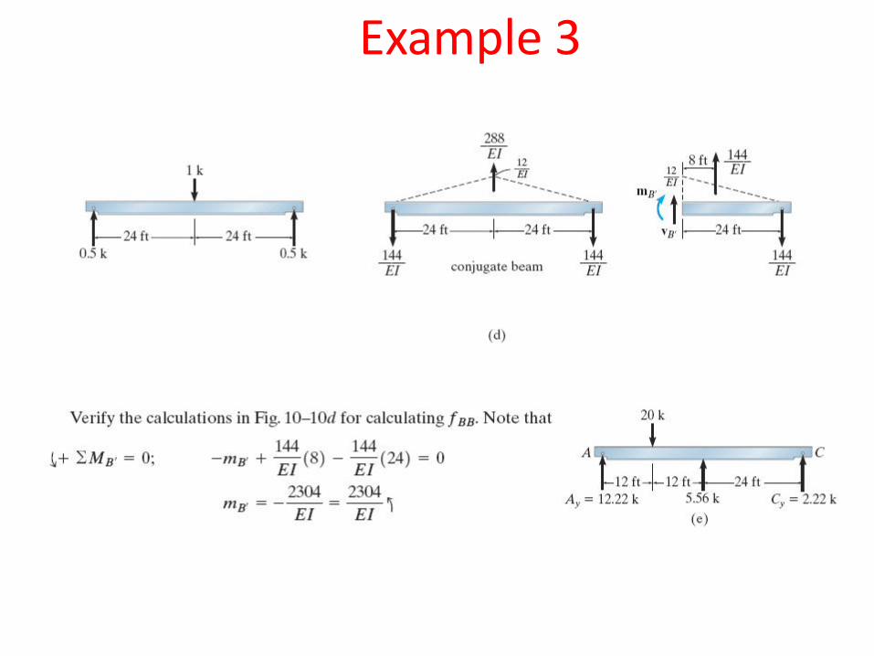
Example 3
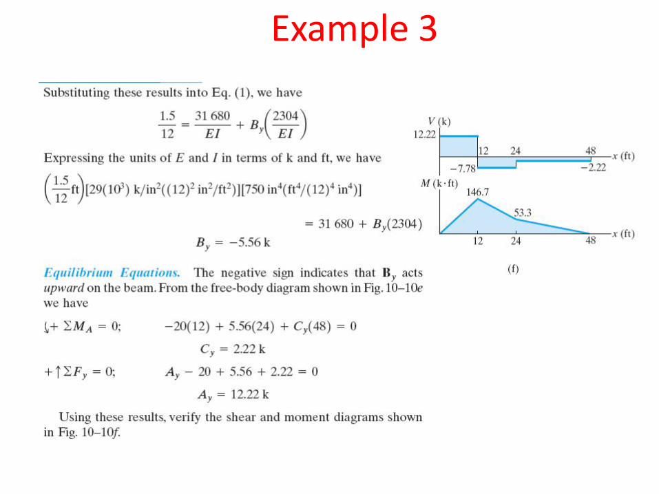
Example 3
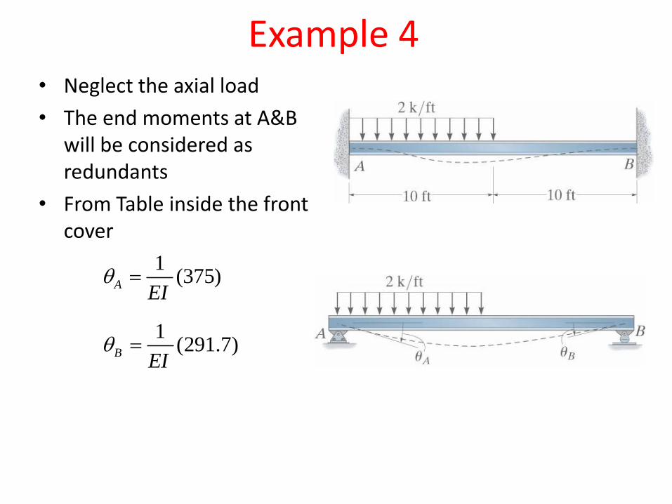
• Neglect the axial load
• The end moments at A&B will be considered as redundants
• From Table inside the front cover
1(375)A
EI
1(291.7)B
EI
Example 4

-
3.33BA
EI
13.33
20(2/3)10
6.67
6.67AA
EI
6.67BB
EI
3.33AB
EI
375 6.67 3.330 A BM M
EI EI EI
291.7 3.33 6.670 A BM M
EI EI EI
45.8 .AM k ft 20.8 .BM k ft
Example 4
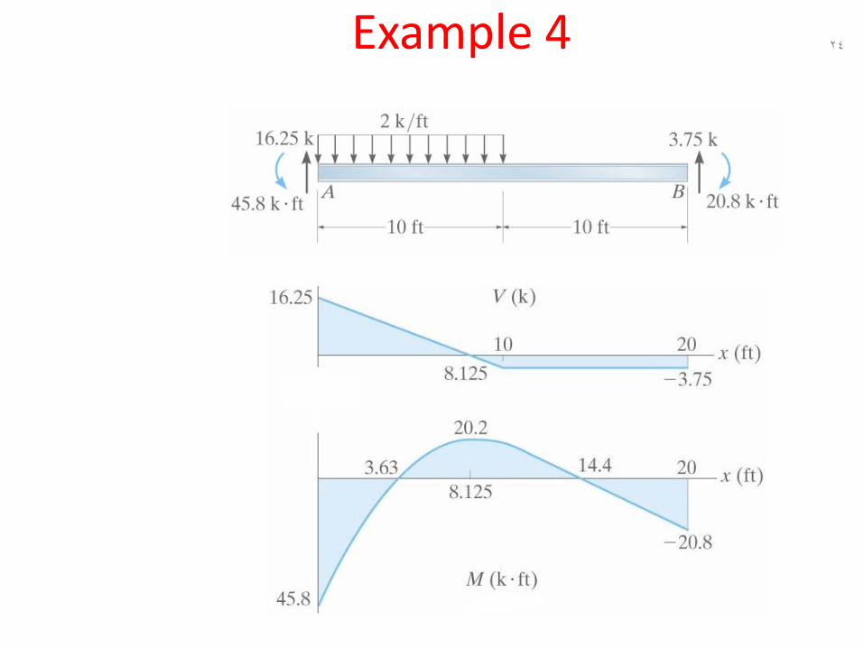
24Example 4
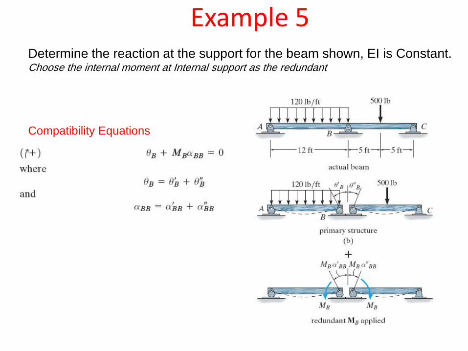
Example 5Determine the reaction at the support for the beam shown, EI is Constant.Choose the internal moment at Internal support as the redundant
Compatibility Equations
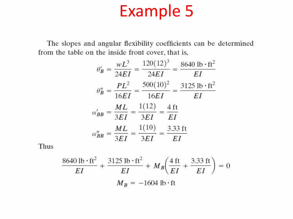
Example 5
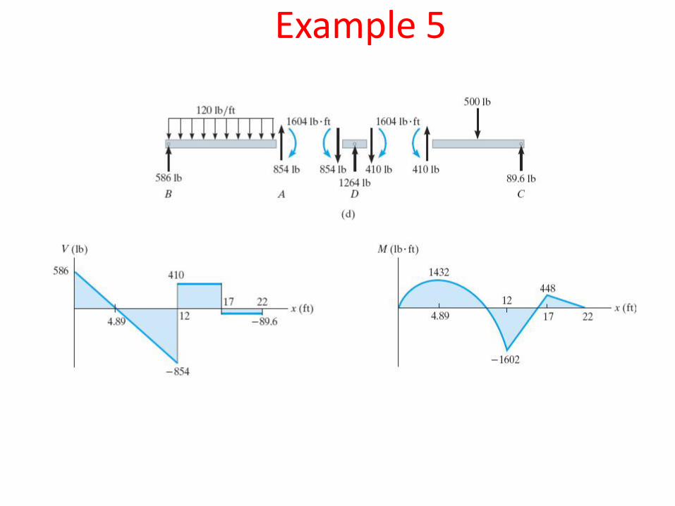
Example 5
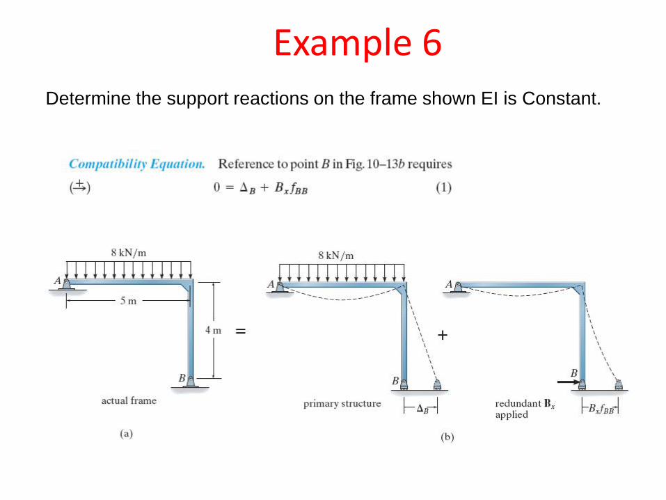
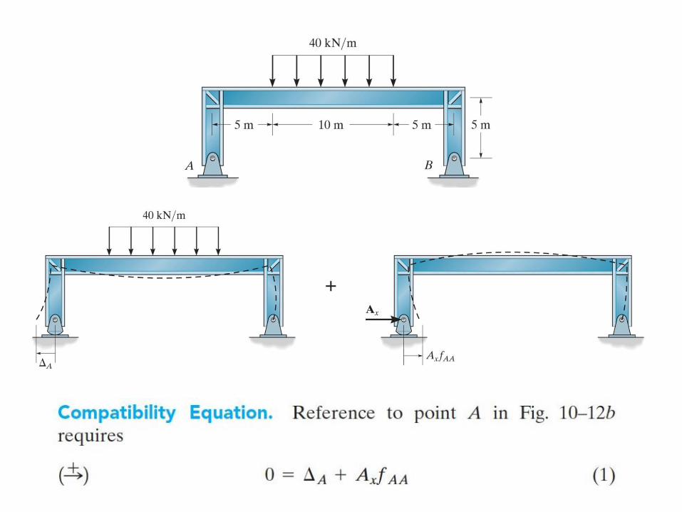
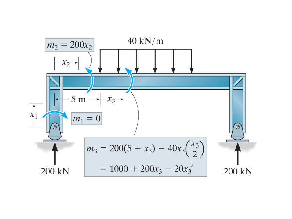
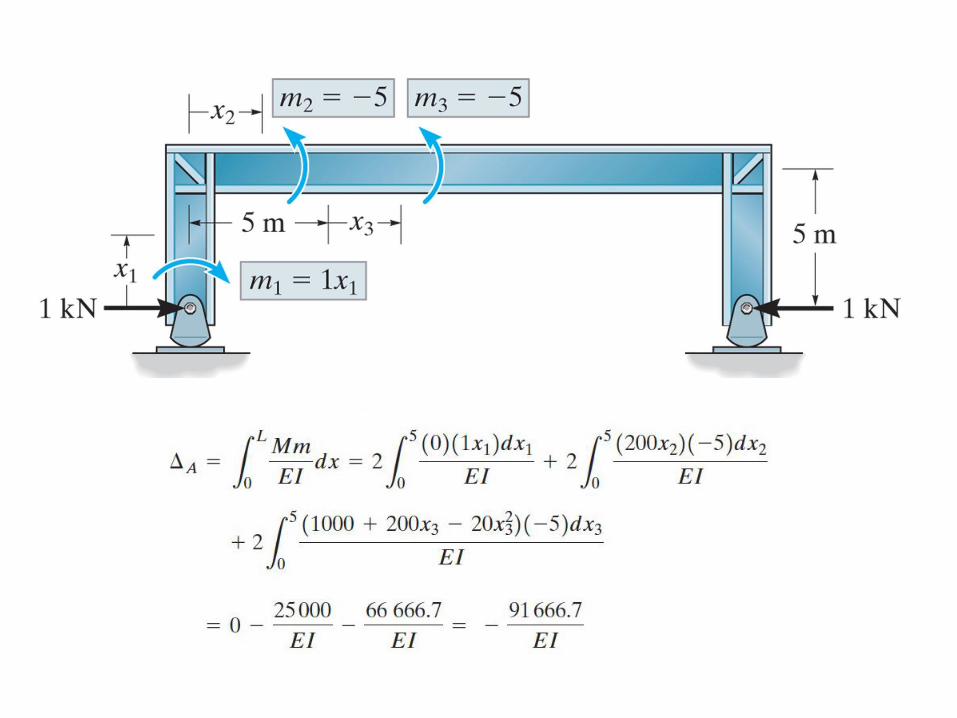
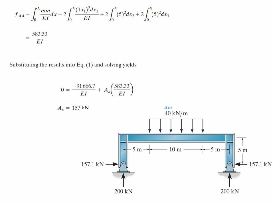
Example 6Determine the support reactions on the frame shown EI is Constant.
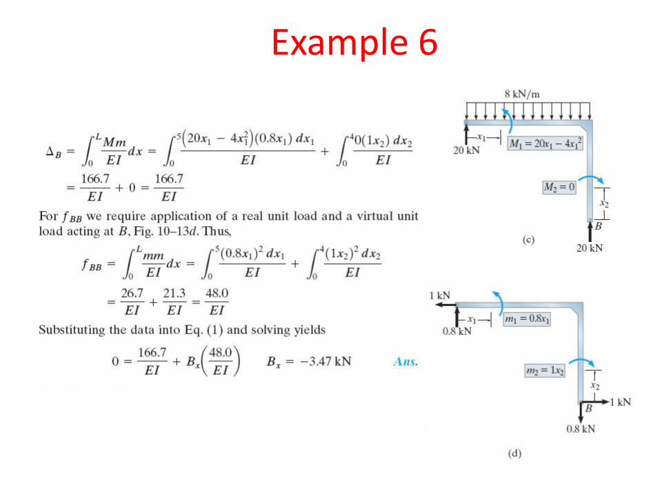
Example 6
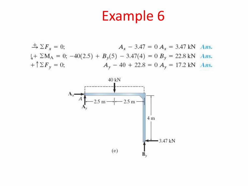
Example 6
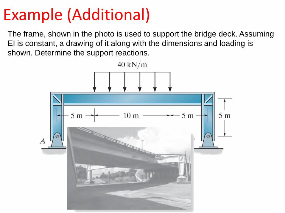
Example (Additional)The frame, shown in the photo is used to support the bridge deck. Assuming
EI is constant, a drawing of it along with the dimensions and loading is
shown. Determine the support reactions.
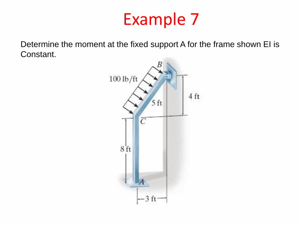
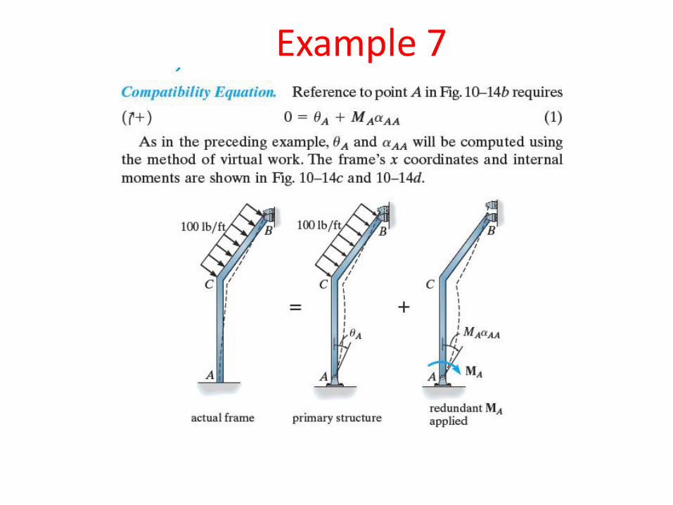
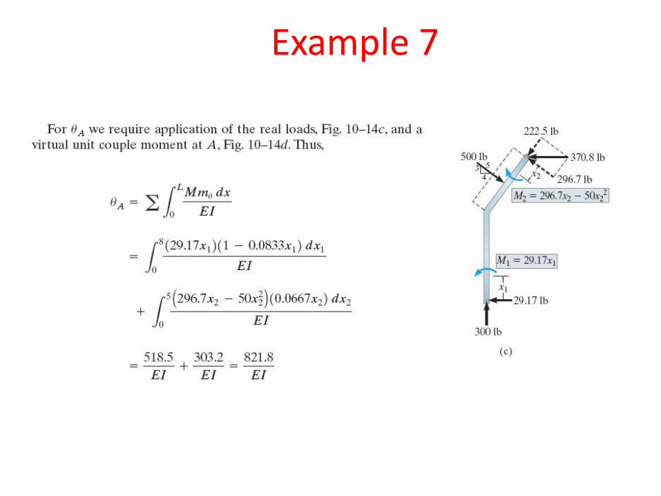
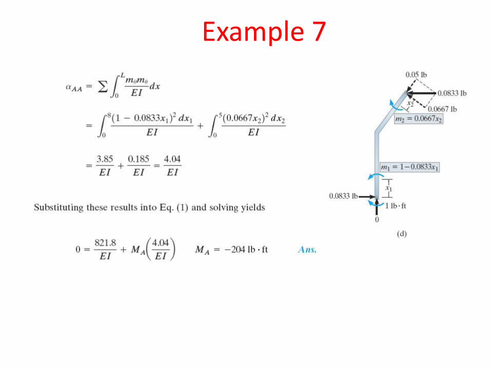
Example 7Determine the moment at the fixed support A for the frame shown EI is
Constant.
Example 7
Example 7
Example 7
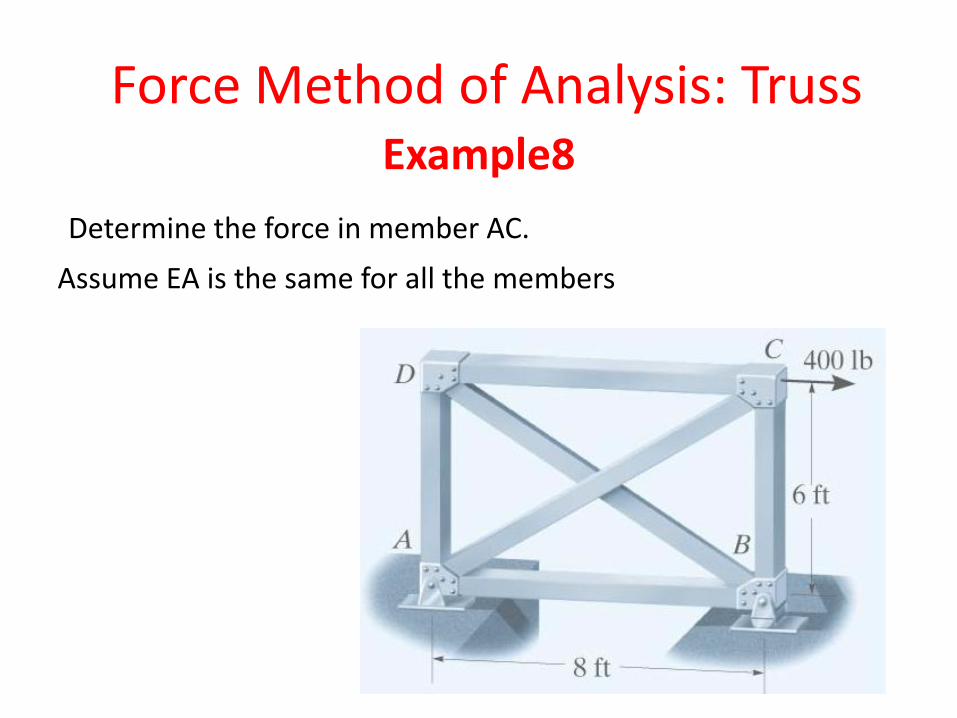
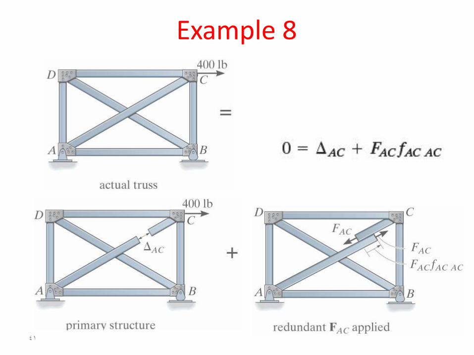
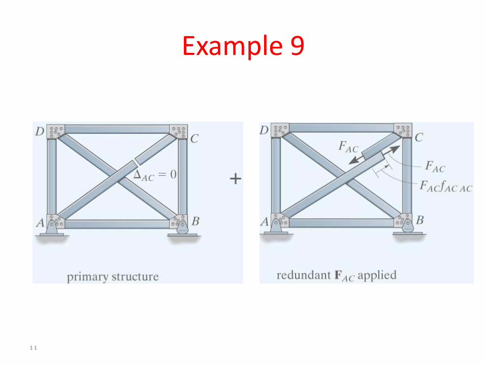
Force Method of Analysis: TrussExample8
Determine the force in member AC.
Assume EA is the same for all the members
41
Example 8
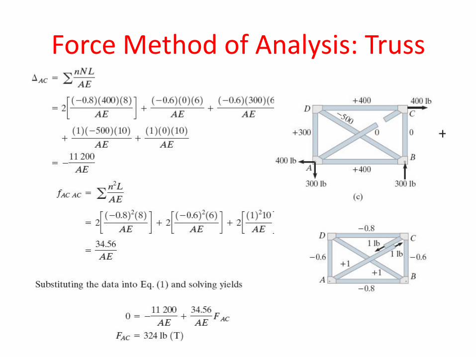
Force Method of Analysis: Truss
43
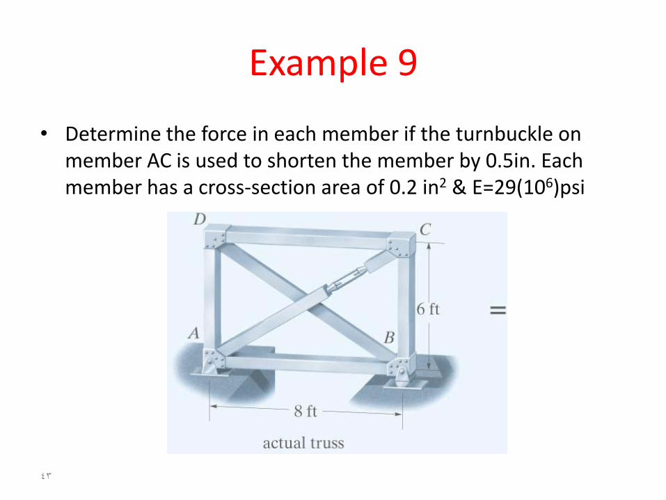
Example 9
• Determine the force in each member if the turnbuckle on member AC is used to shorten the member by 0.5in. Each member has a cross-section area of 0.2 in2 & E=29(106)psi
44
Example 9
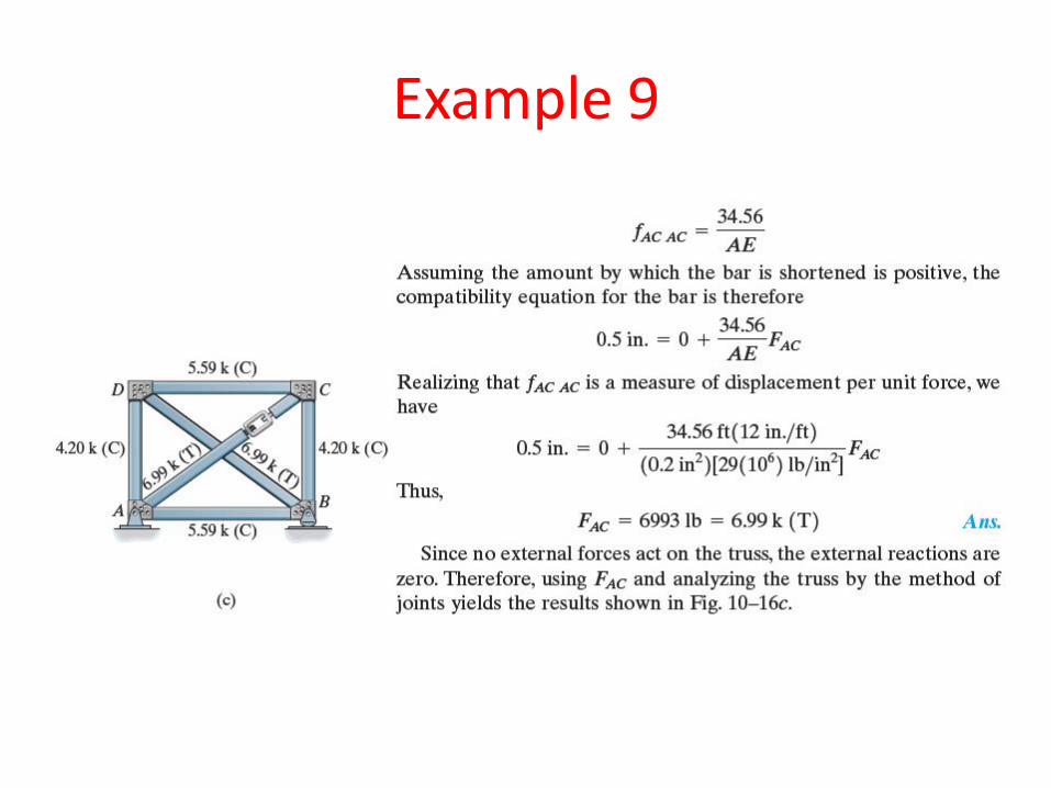
Example 9
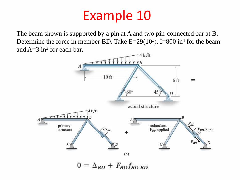
Example 10The beam shown is supported by a pin at A and two pin-connected bar at B.
Determine the force in member BD. Take E=29(103), I=800 in4 for the beam
and A=3 in2 for each bar.
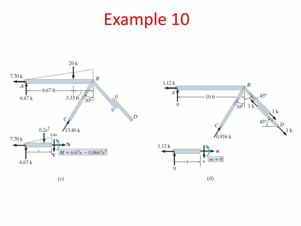
Example 10
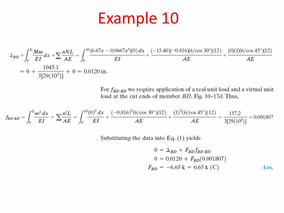
Example 10
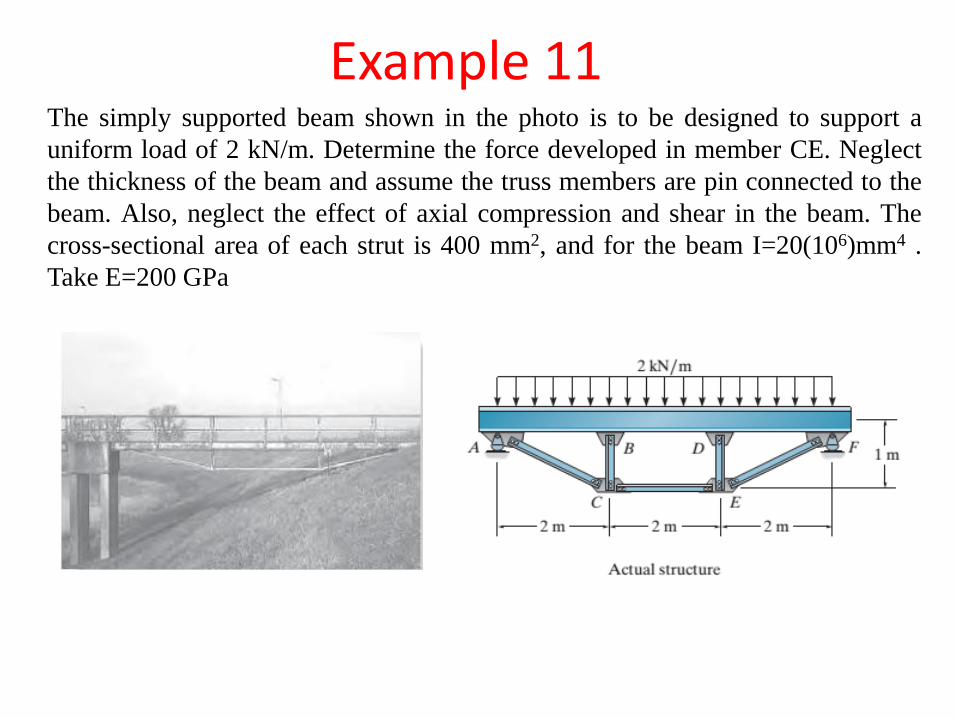
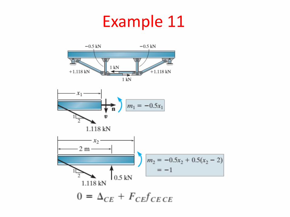
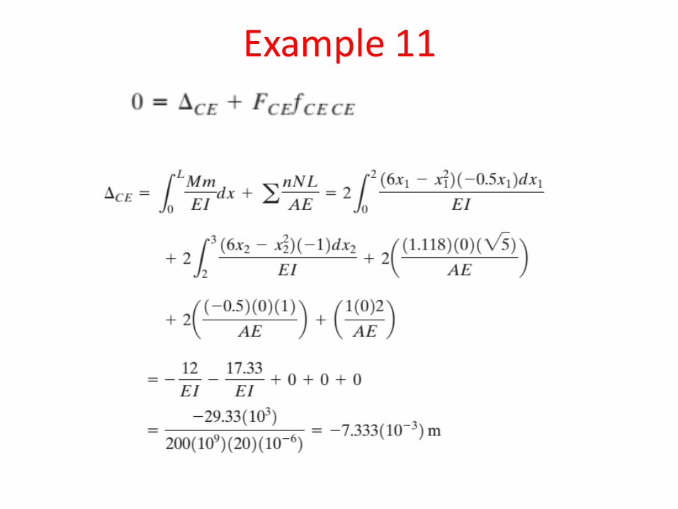
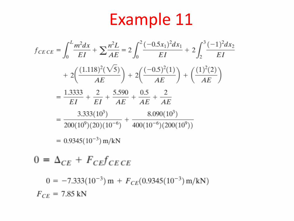
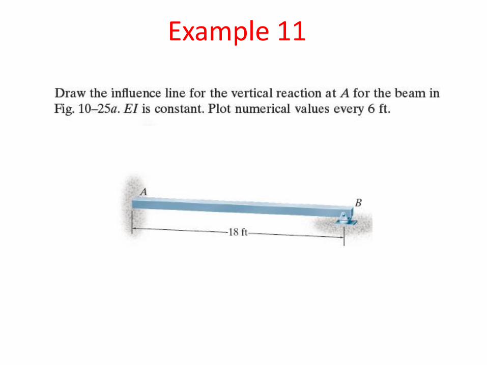
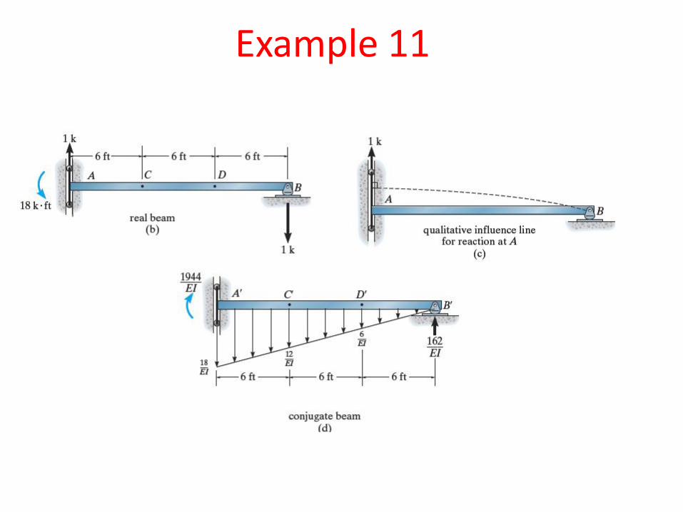
Example 11The simply supported beam shown in the photo is to be designed to support a
uniform load of 2 kN/m. Determine the force developed in member CE. Neglect
the thickness of the beam and assume the truss members are pin connected to the
beam. Also, neglect the effect of axial compression and shear in the beam. The
cross-sectional area of each strut is 400 mm2, and for the beam I=20(106)mm4 .
Take E=200 GPa
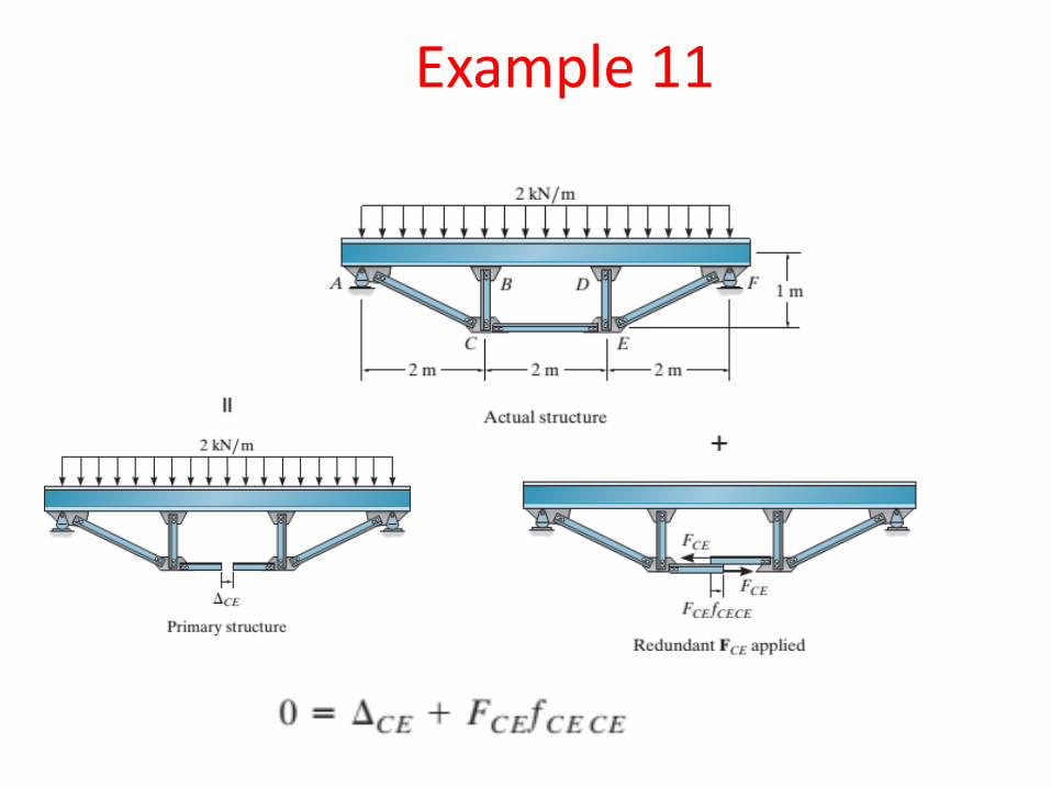
Example 11
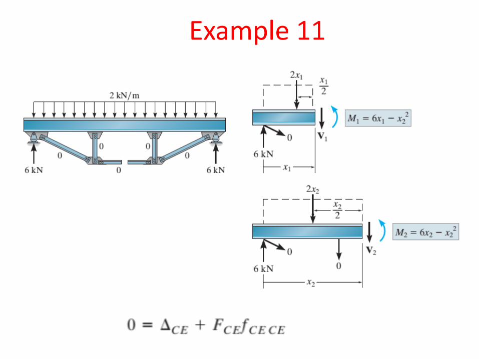
Example 11
Example 11
Example 11
Example 11
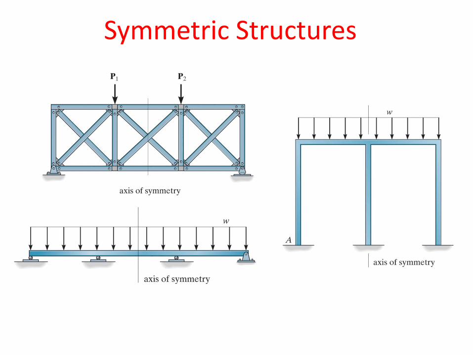
Symmetric Structures
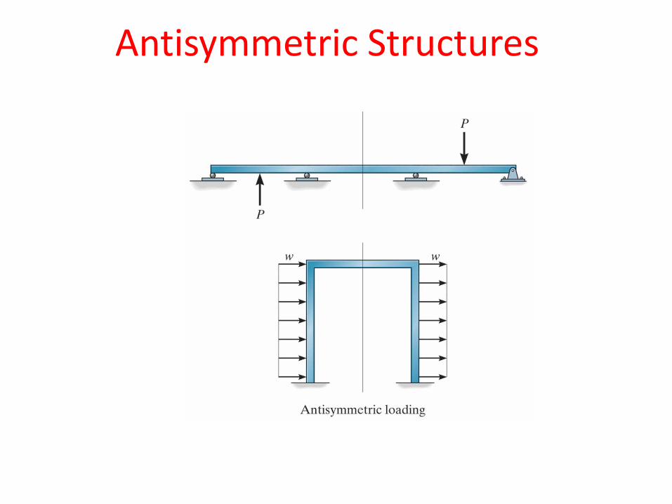
Antisymmetric Structures
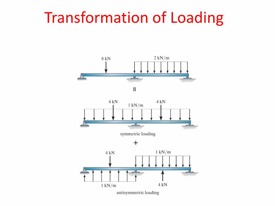
Transformation of Loading
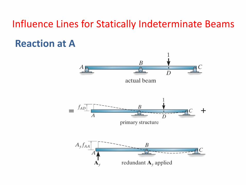
Influence Lines for Statically Indeterminate Beams
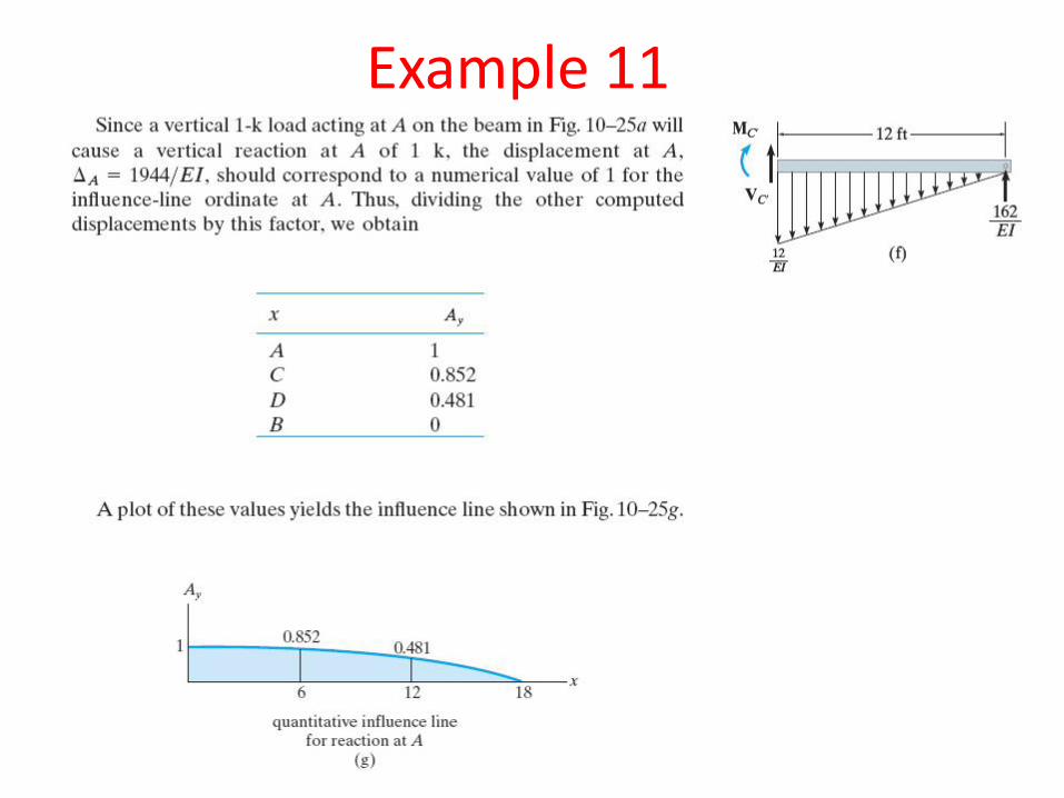
Reaction at A
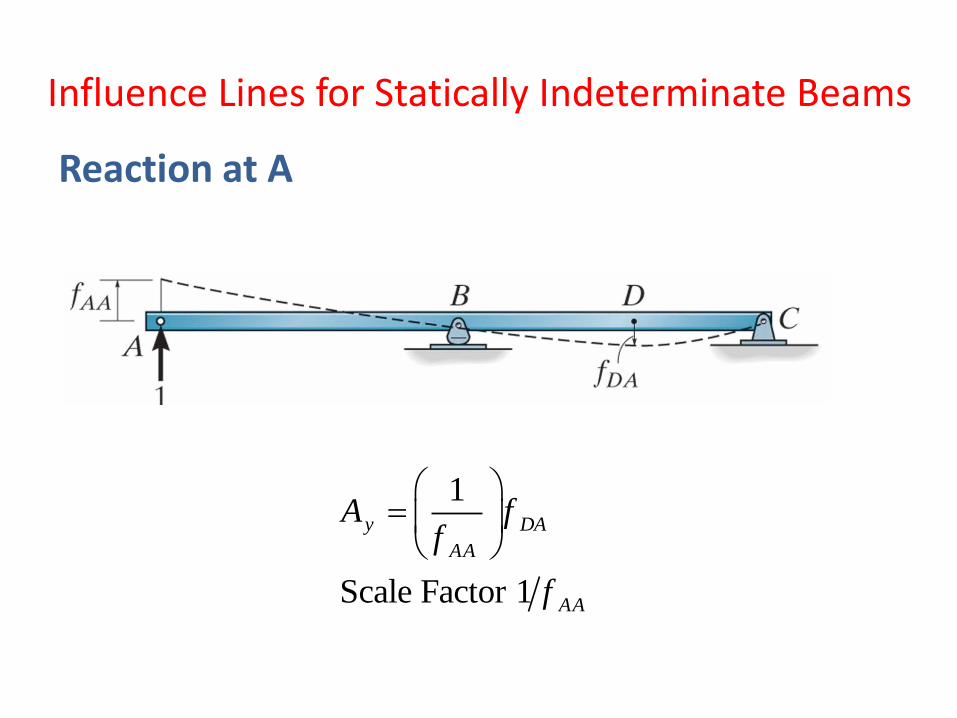
1
Scale Factor 1
y DA
AA
AA
A ff
f
Influence Lines for Statically Indeterminate Beams
Reaction at A
1
Scale Factor 1
E DE
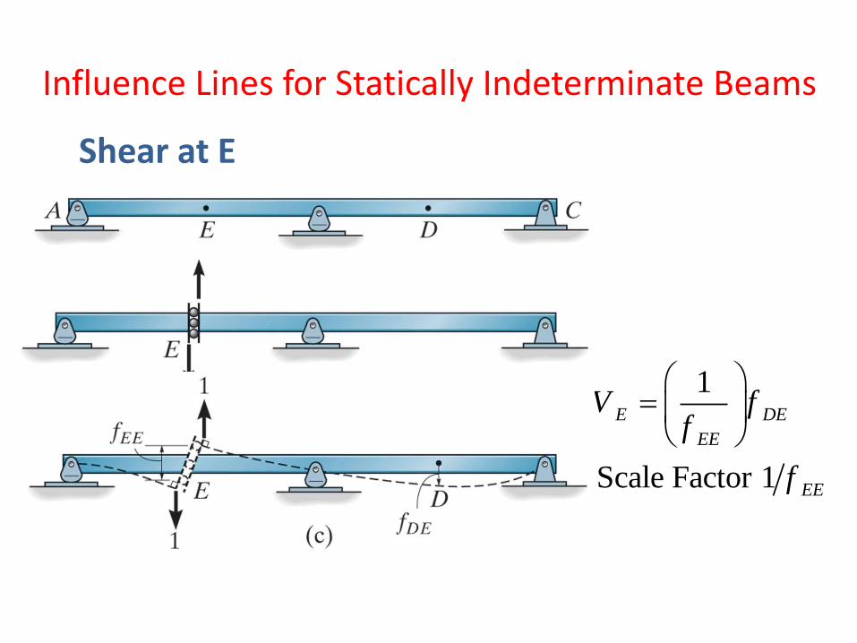
EE
EE
V ff
f
Influence Lines for Statically Indeterminate Beams
Shear at E
Influence Lines for Statically Indeterminate Beams
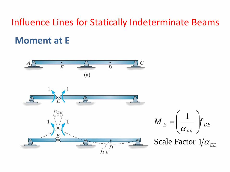
Moment at E
1
Scale Factor 1
E DE
EE
EE
M f
Example 11
Example 11
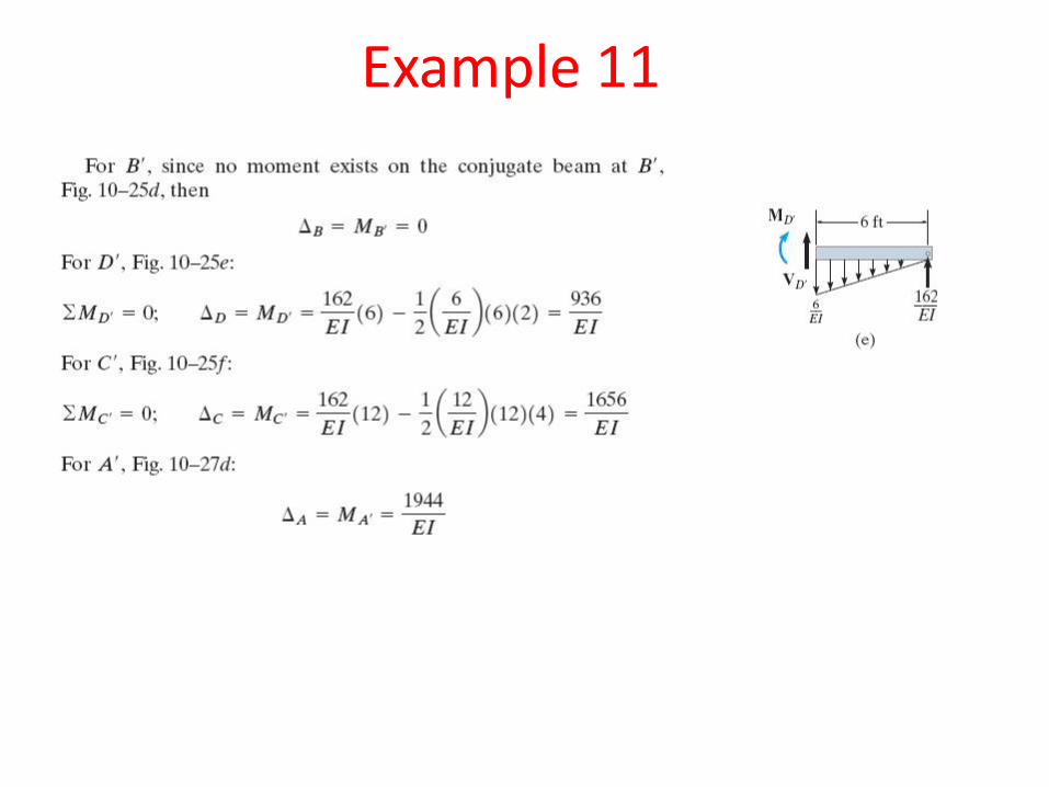
Example 11
Example 11
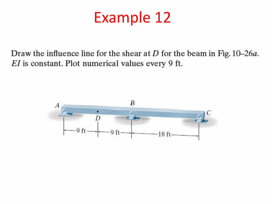
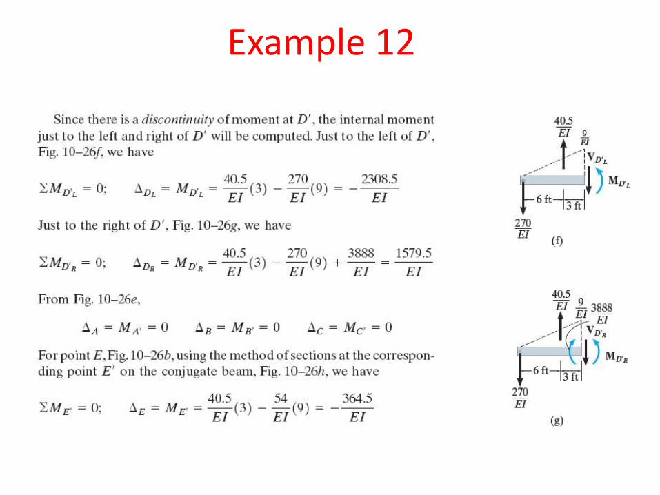
Example 12
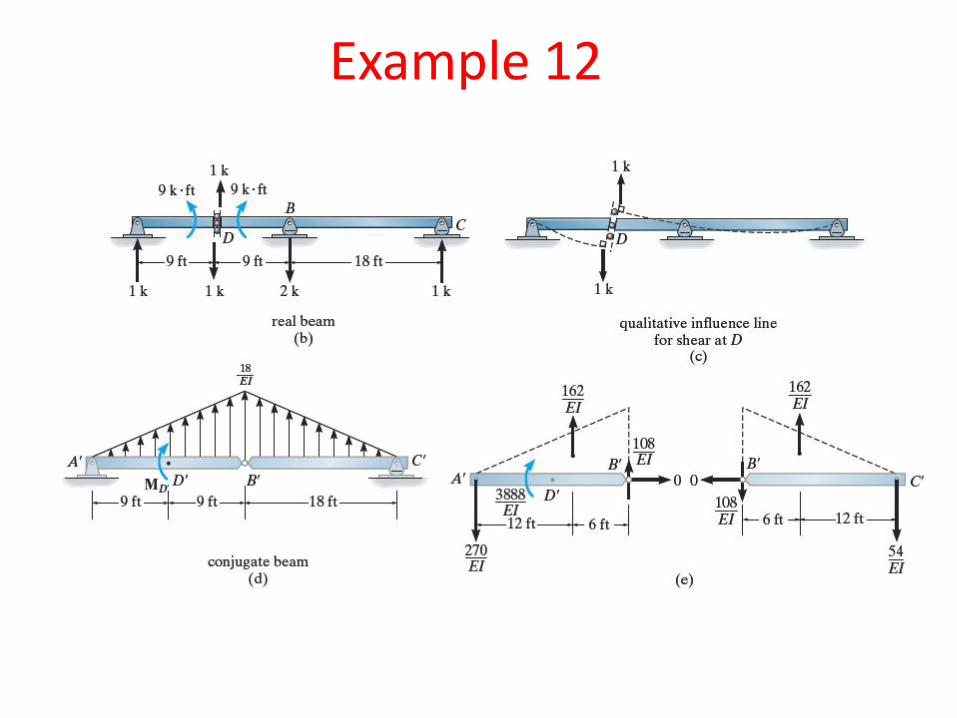
Example 12
Example 12
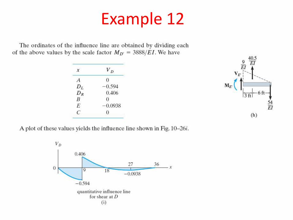
Example 12
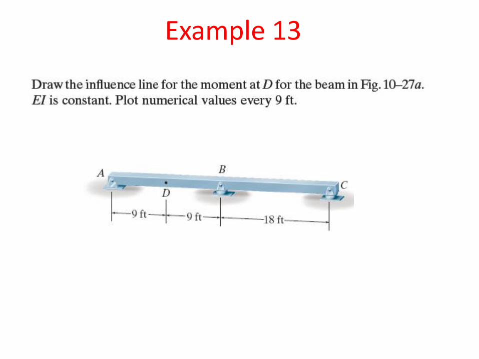
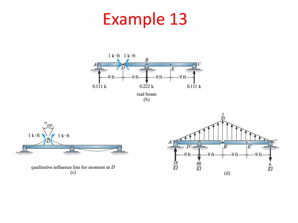
Example 13
Example 13
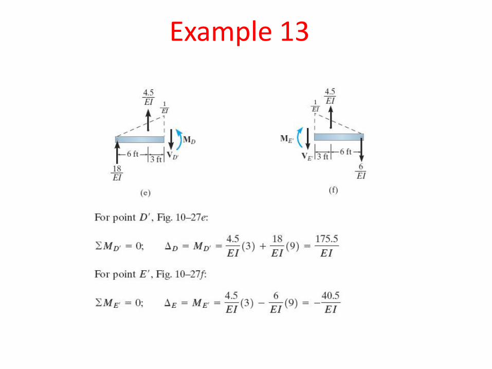
Example 13
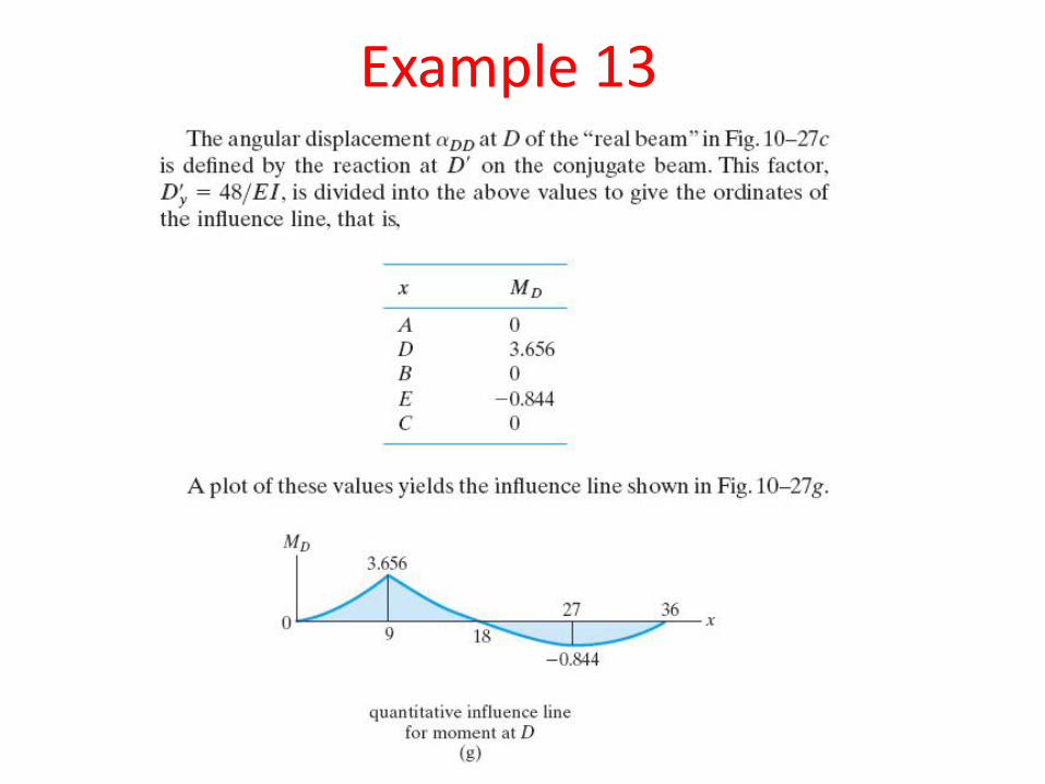
Example 13
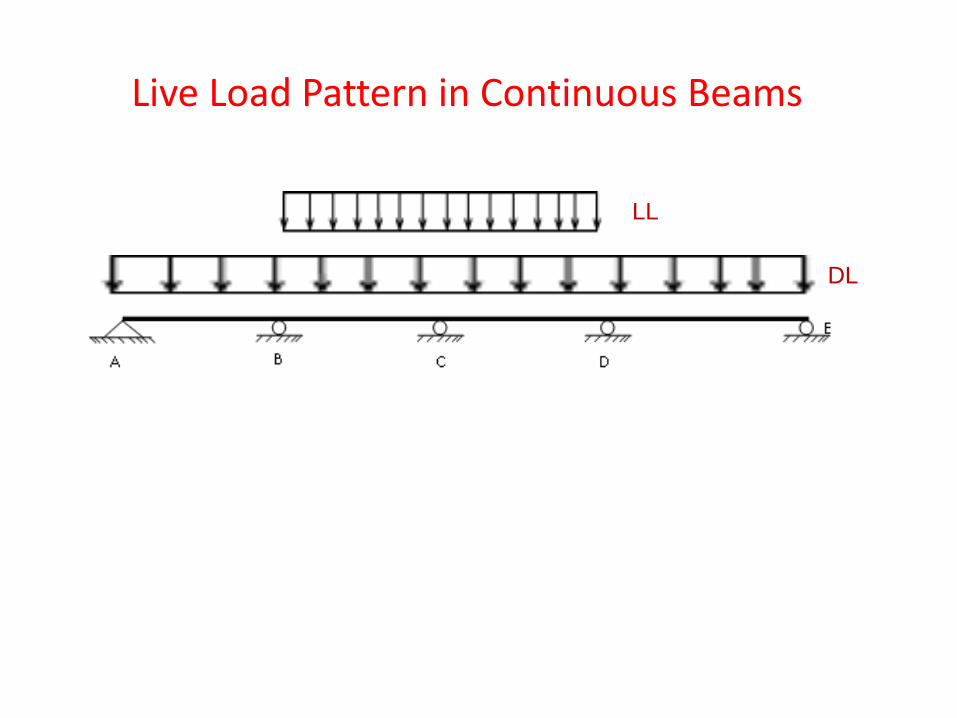
Live Load Pattern in Continuous Beams
LL
DL
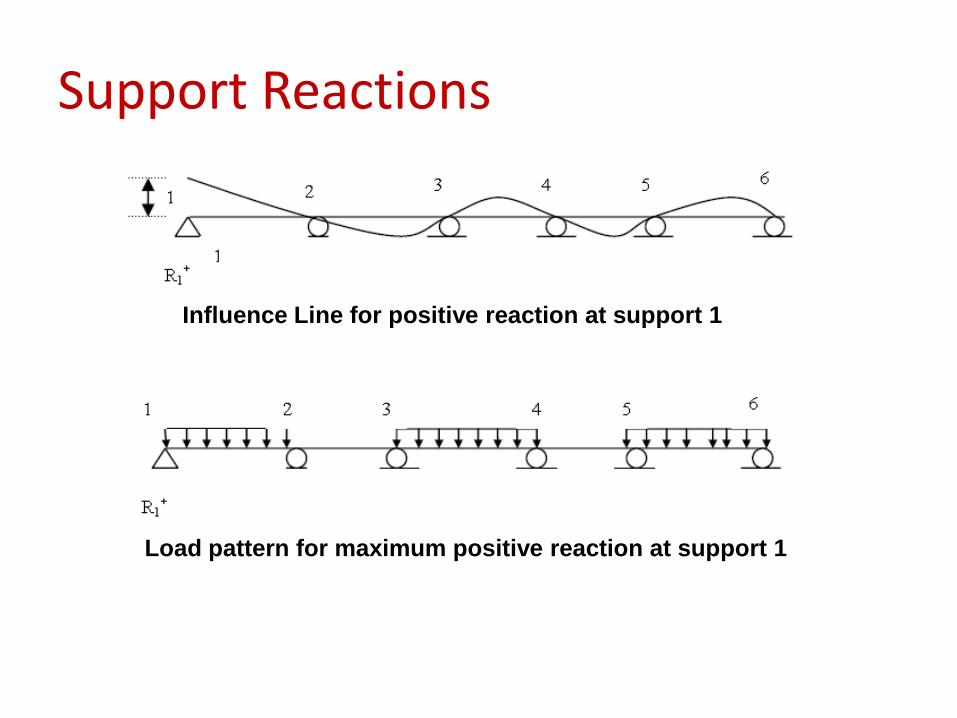
Support Reactions
Influence Line for positive reaction at support 1
Load pattern for maximum positive reaction at support 1
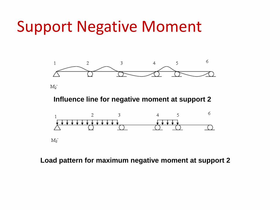
Support Negative Moment
Influence line for negative moment at support 2
Load pattern for maximum negative moment at support 2
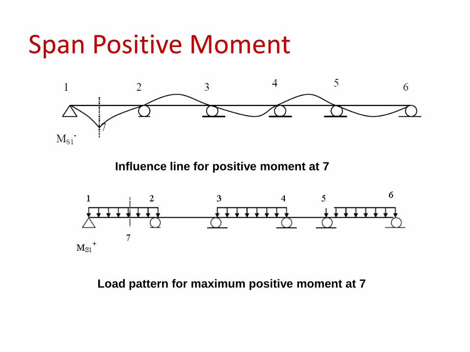
Span Positive Moment
Influence line for positive moment at 7
Load pattern for maximum positive moment at 7
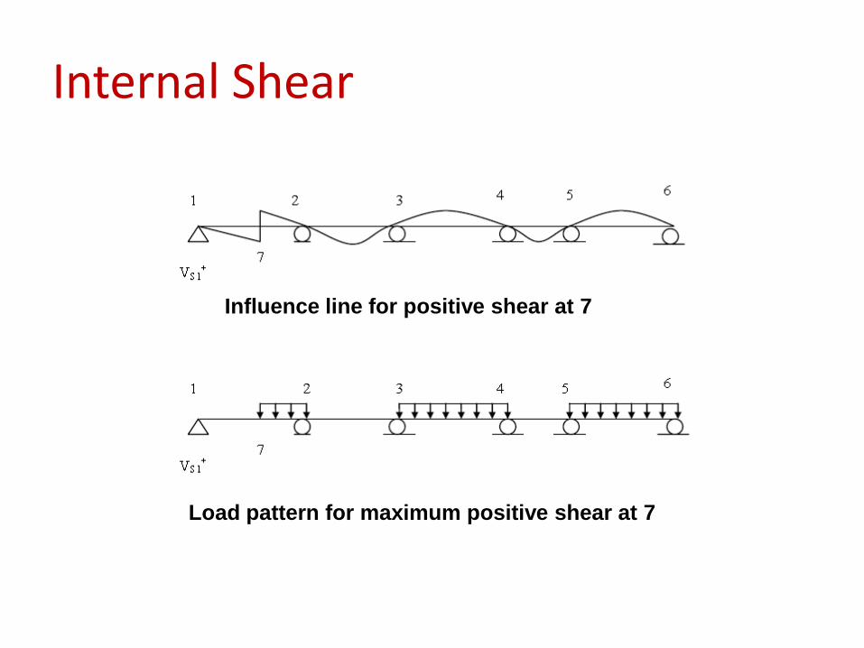
Internal Shear
Influence line for positive shear at 7
Load pattern for maximum positive shear at 7
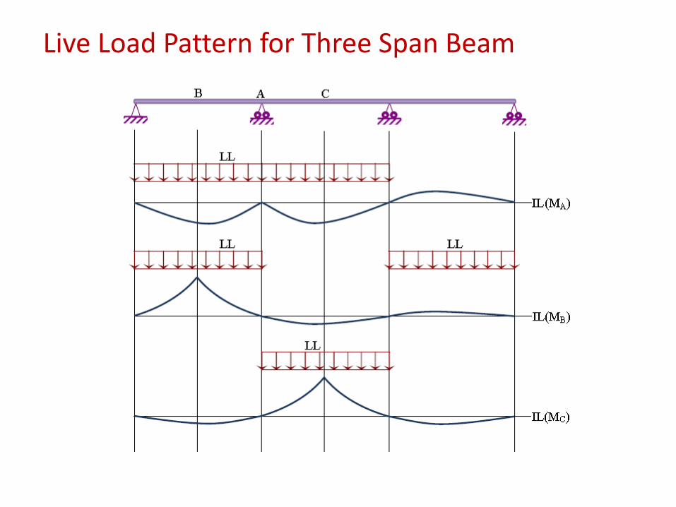
Live Load Pattern for Three Span Beam