Embed Size (px)
Citation preview
������������������� ������� ������������������������������������������ ! ISSN 2229-5518
Analysis of Self-supported Steel Chimney with the
Effects of Manhole and Geometrical Properties Kirtikanta Sahoo, Pradip Sarkar, Robin Davis P.
Abstract— Industrial chimneys are high rise structures as compared to surroundings. Material of construction and structural support plays a vital role for selecting which type of chimney is suitable for a particular purpose. Self-supporting steel chimneys are normally provided for lower height case. Wind load is a predominant force in such types of structures. Analysis and design of chimney depends on various factors such as wind force, environmental conditions, types of materials used and cross sectional area of the chimney. Manholes are provided at the bottom in the chimney for inspection purposes. The presence of manhole reduces the area and hence the stiffness of the chimney. In the present study investigates the stresses, deflection and mode shapes of the chimney due to the presence of an inspection manhole. Maximum Von Mises stress, top deflection and mode shapes were calculated using finite element software ANSYS. The results show that, the due to the presence of manhole, the stresses are increased by approximately 1.5 times and frequency is decreased by approximately 1.12 times.
Key words — Steel chimney, Dynamic wind load, Static wind load, Von mises stress, Deflection, Mode shape, Man hole
—————————— � ——————————
1 INTRODUCTION
HIS paper deals with the analysis of self-supported-steel chim-neys. Tall steel chimneys are presently planned in compliance
with various codes of practice (IS 65331, 2, CICIND3 etc.). The chim-ney is considered as cantilever column with tubular cross section for analysis. Wind loads, temperature loads, seismic loads and dead loads are considered for design purpose. But apart from these loads, wind load is considered as most vital load due to height of the struc-ture. The effect of wind can be divided into two components: (a) along-wind effect (b) across-wind effect. But the across-wind effect is most critical and unpredictable. The bottom portion of the chim-ney is constructed as conical flare for better stability and for easy entrance of flue gases. Design forces in a chimney is very sensitive to its geometrical parameters such as base and top diameter of the chimney, height of the flare, height of the chimney and thickness of the chimney shell. Height of the chimney is goverened by environ-mental conditions. As per recommendations of the Ministry of Envi-ronment and Forests5, Govt. of India, height of a self-supporting steel chimney should be as follows: +=
m
ntinlocatioldingheighTallestBuim
Q
h
30
6
14
max
3.0
Where Q= total SO2 emission from the plant in kg/hr and h = height of the steel chimney in m.
As per IS-6533 Part-1:19891 , height of steel chimney is also a func-tion of environmental condition as follows:
4
3
8 =CV
AMFDh
Where A = coefficient of temperature gradient of atmosphere respon-sible for horizontal and vertical mixing of plume, M = estimated mass rate of emission of pollutants in g/s, F = dimensionless coeffi-cient of rate of precipitation, C = maximum permissible ground level concentration of pollutant in mg/m3, gases, m3/s, D = diameter of stack at the exit of the chimney in m. V = estimated volume rates of emission of total flueme.
Also, inside diameter of the chimney shell at top as per IS 6533 (Part 1): 1989 is given by:
VQ
exit
tD∏
=4
Where D = inside diameter of the chimney at top in m, Qt = Quantity of the gas in m3/s, and Vexit = Velocity of the flue gas at exit point of chimney in m/s. However, the diameter shall be so chosen that velocity of the flue gas at exit point of chimney will not exceed 30m/s, under any circumstances. As per IS 6533 (Part 2): 19892 there are some limitations for the proportions of the basic dimensions from structural engineering con-siderations as follows
a. Minimum outside diameter of the unlined chimney at the top should be one twentieth of the height of the cylindrical portion of the chimney.
b. Minimum outside diameter of the unlined flared chimney at the base should be 1.6 times the outside diameter of the chimney at top.
With these parameters, the basic dimensions of the Chimney are checked to understand the code limitations. A lot of 66 of chimneys
T
———————————————— • Kirti Kanta Sahoo, Ph.D. Student, National Institute of Technolo-
gy, Rourkela, Orissa 769008 India PH-09937195845. E-mail: [email protected]
• Pradip Sarkar, Asso. Professor, National Institute of Technology, Rourkela, Orissa 769008 India. PH-06612326.E-mail: [email protected]
• Robin Davis P., Asst. Professor, National Institute of Technology, Rourkela, Orissa 769008 India. E-mail: [email protected]
250
IJSER
������������������� ������� ������������������������������������������ ! ISSN 2229-5518
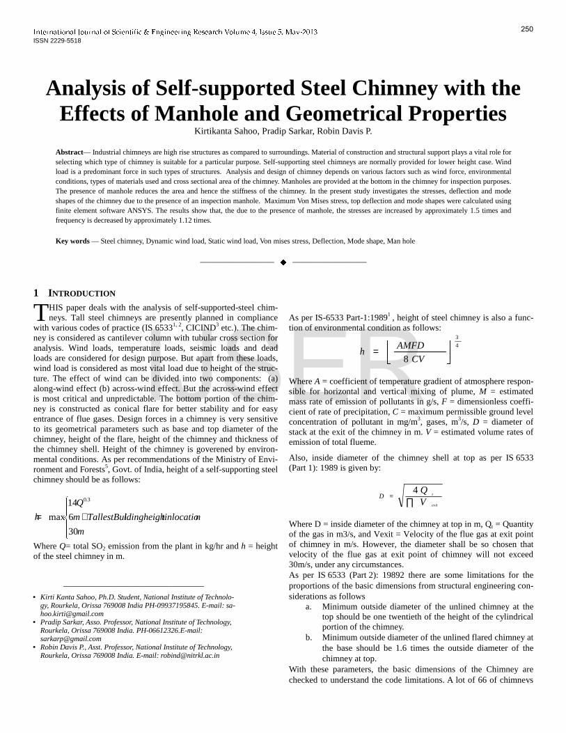
are considered for the present study. 2 ANALYSES OF THE SELECTED CHIMNEYS 2.1 Effect of Geometry From the discussions in the previous section it is apparent that top-to-base diameter ratio and height-to-base diameter ratio are the two essential factors that characterize the geometry of a self-supporting chimney. For the selected Chimneys top-to-base diameter ratio and height-to-base diameter ratio varies with constant thickness and flared base diameter. Fig. 1 presents the different parameters of the selected chimneys according to code limitations. This figure shows that the selected chimneys cover wide range of geometry.
2.2 Effect of manhole
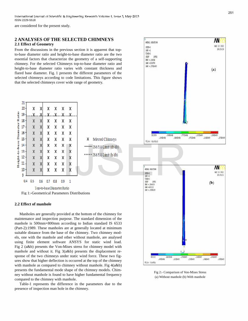
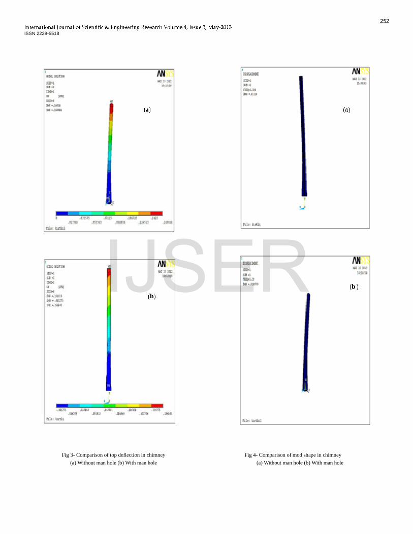
Manholes are generally provided at the bottom of the chimney for maintenance and inspection purpose. The standard dimension of the manhole is 500mm×800mm according to Indian standard IS 6533 (Part-2):1989. These manholes are at generally located at minimum suitable distance from the base of the chimney. Two chimney mod-els, one with the manhole and other without manhole, are analysed using finite element software ANSYS for static wind load. Fig 2 (a&b) presents the Von-Mises stress for chimney model with manhole and without it. Fig 3(a&b) presents the displacement re-sponse of the two chimneys under static wind force. These two fig-ures show that higher deflection is occurred at the top of the chimney with manhole as compared to chimney without manhole. Fig 4(a&b) presents the fundamental mode shape of the chimney models. Chim-ney without manhole is found to have higher fundamental frequency compared to the chimney with manhole.
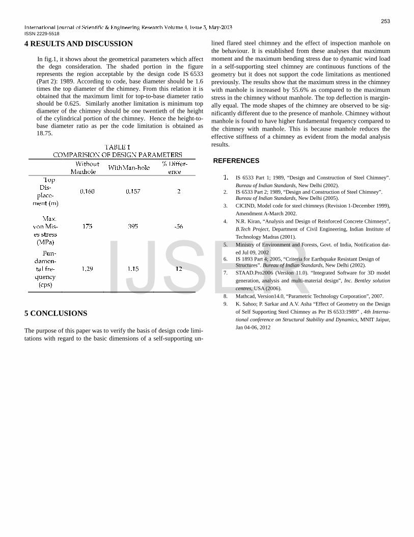
Table-1 represents the difference in the parameters due to the presence of inspection man hole in the chimney.
Fig 2:- Comparison of Von-Mises Stress
(a) Without manhole (b) With manhole
Fig 1:-Geometrical Parameters Distributions
(a)
(b)
251
IJSER
������������������� ������� ������������������������������������������ ! ISSN 2229-5518
Fig 3- Comparison of top deflection in chimney
(a) Without man hole (b) With man hole
Fig 4- Comparison of mod shape in chimney (a) Without man hole (b) With man hole
(b) (a) (a)
(b)
(a) 252
IJSER
������������������� ������� ������������������������������������������ ! ISSN 2229-5518
4 RESULTS AND DISCUSSION In fig.1, it shows about the geometrical parameters which affect
the degn consideration. The shaded portion in the figure represents the region acceptable by the design code IS 6533 (Part 2): 1989. According to code, base diameter should be 1.6 times the top diameter of the chimney. From this relation it is obtained that the maximum limit for top-to-base diameter ratio should be 0.625. Similarly another limitation is minimum top diameter of the chimney should be one twentieth of the height of the cylindrical portion of the chimney. Hence the height-to-base diameter ratio as per the code limitation is obtained as 18.75.
5 CONCLUSIONS The purpose of this paper was to verify the basis of design code limi-tations with regard to the basic dimensions of a self-supporting un-
lined flared steel chimney and the effect of inspection manhole on the behaviour. It is established from these analyses that maximum moment and the maximum bending stress due to dynamic wind load in a self-supporting steel chimney are continuous functions of the geometry but it does not support the code limitations as mentioned previously. The results show that the maximum stress in the chimney with manhole is increased by 55.6% as compared to the maximum stress in the chimney without manhole. The top deflection is margin-ally equal. The mode shapes of the chimney are observed to be sig-nificantly different due to the presence of manhole. Chimney without manhole is found to have higher fundamental frequency compared to the chimney with manhole. This is because manhole reduces the effective stiffness of a chimney as evident from the modal analysis results.
REFERENCES 1. IS 6533 Part 1; 1989, “Design and Construction of Steel Chimney”.
Bureau of Indian Standards, New Delhi (2002). 2. IS 6533 Part 2; 1989, “Design and Construction of Steel Chimney”.
Bureau of Indian Standards, New Delhi (2005). 3. CICIND, Model code for steel chimneys (Revision 1-December 1999),
Amendment A-March 2002.
4. N.R. Kiran, “Analysis and Design of Reinforced Concrete Chimneys”,
B.Tech Project, Department of Civil Engineering, Indian Institute of
Technology Madras (2001).
5. Ministry of Environment and Forests, Govt. of India, Notification dat-
ed Jul 09, 2002 6. IS 1893 Part 4; 2005, “Criteria for Earthquake Resistant Design of
Structures”. Bureau of Indian Standards, New Delhi (2002). 7. STAAD.Pro2006 (Version 11.0). “Integrated Software for 3D model
generation, analysis and multi-material design”, Inc. Bentley solution
centres, USA (2006).
8. Mathcad, Version14.0, “Parametric Technology Corporation”, 2007.
9. K. Sahoo; P. Sarkar and A.V. Asha “Effect of Geometry on the Design
of Self Supporting Steel Chimney as Per IS 6533:1989” , 4th Interna-
tional conference on Structural Stability and Dynamics, MNIT Jaipur,
Jan 04-06, 2012
TABLE 1 COMPARISION OF DESIGN PARAMETERS Without Manhole WithMan-hole % Differ-ence Top Dis-place-ment (m) 0.160 0.157 2 Max. von Mis-es stress (MPa) 175 395 -56 Fun-damen-tal fre-quency (cps) 1.29 1.15 12
253
IJSER


![[BS en 13084-2-2007] -- Free-standing Chimneys. Concrete Chimneys](https://img.pdfslide.us/doc/110x75/577c7e1f1a28abe054a09ebb/bs-en-13084-2-2007-free-standing-chimneys-concrete-chimneys.jpg)