Embed Size (px)
Citation preview
Vol.13, No.2 EARTHQUAKE ENGINEERING AND ENGINEERING VIBRATION June, 2014
Earthq Eng & Eng Vib (2014) 13: 327-335 DOI: 10.1007/s11803-014-0234-0
Analysis of seismic disaster failure mechanism and dam-break simulation of high arch dam
Zhang Jingkui1† and Zhang Liaojun2‡
1. Anhui and Huaihe River Institute of Hydraulic Research, Bengbu 233000, China
2. College of Water Conservancy and Hydropower Engineering, Hohai University, Nanjing 210098, China
Abstract: Based on a Chinese national high arch dam located in a meizoseismal region, a nonlinear numerical analysis model of the damage and failure process of a dam-foundation system is established by employing a 3-D deformable distinct element code (3DEC) and its re-development functions. The proposed analysis model considers the dam-foundation-reservoir coupling effect, infl uence of nonlinear contact in the opening and closing of the dam seam surface and abutment rock joints during strong earthquakes, and radiation damping of far fi eld energy dissipation according to the actual workability state of an arch dam. A safety assessment method and safety evaluation criteria is developed to better understand the arch dam system disaster process from local damage to ultimate failure. The dynamic characteristics, disaster mechanism, limit bearing capacity and the entire failure process of a high arch dam under a strong earthquake are then analyzed. Further, the seismic safety of the arch dam is evaluated according to the proposed evaluation criteria and safety assessment method. As a result, some useful conclusions are obtained for some aspects of the disaster mechanism and failure process of an arch dam. The analysis method and conclusions may be useful in engineering practice.
Keywords: high arch dam; complex foundation; 3DEC; disaster mechanism; dam-break process simulation; seismic safety evaluation
Correspondence to: Zhang Jingkui, Anhui and Huaihe River Institute of Hydraulic Research, No.771, Zhihuai Road, Bengbu 233000, Anhui, China Tel: +86-552-3051657; Fax:+86-552-3051657E-mail: [email protected]
†Assistant Professor; ‡ProfessorSupported by: National Natural Science Foundation of China
under Grant No. 90510017Received May 13, 2012; Accepted November 11, 2013
1 Introduction
Damage to arch dams under earthquakes is a process which extends gradually from local damage to overall instability. Since the arch dam itself can be adjusted through stress redistribution, local cracking or sliding of the dam body and abutment rock mass is permitted by the Chinese national and international aseismic design standards. However, local excessive cracking and sliding of the abutment rock mass will lead to dam instability due to insuffi cient strength and severe deterioration of the stress state in the weak parts of the dam body. At present, in the seismic safety analysis, the “dam-break” concept is quite fuzzy, and there is an embarrassing lack of explicit security evaluation criterion (Chen et al., 2004; Zhang and Chen, 2001; Zhang and Zhang, 2013). Therefore, in this study, the arch dam-foundation system's failure mode, instability criterion, analysis method, and dynamic deformation
coupling effects between the abutment rock and the dam body are researched. Further, dynamic security evaluation criterion to determine the arch dam system disaster process from local damage to ultimate failure is discussed to explore the damage mechanisms, limit bearing capacity as well as the entire failure process of the dam-foundation system under a strong earthquake (Lin, 2006; Tu and Chang, 2006; Bathe and Soctt, 1985; Bathe, 1997; Bathe and Bouzinov, 1997).
A 3-D deformable distinct element method proposed by Cundall (1971a) is based on Newton's second Law, and solves the node motion equation through application of the dynamic relaxation method. The method can not only simulate large displacement, large rotation and other mechanical behaviors of a discontinuous medium, but can also introduce all kinds of constitutive relations of material nonlinearity and contact nonlinearity. Moreover, it can obtain a deformation and stress analysis of a continuous and discontinuous medium system by selecting appropriate contact face parameters. Therefore, the method has outstanding advantages in seismic damage process analysis and dam-break simulation of a dam-foundation-reservoir coupling system (Sawamoto et al., 1998; Zhang, 2008; Hou, 2005; Zhang et al., 1997; Pekau and Cui, 2004). Combined with an arch dam project, a nonlinear numerical analysis model is established through the application of a three-dimensional deformable distinct element code (3DEC) in this study.
328 EARTHQUAKE ENGINEERING AND ENGINEERING VIBRATION Vol.13
The model can adequately refl ect both the sliding of potential sliding blocks of the abutment and the entire development process from local damage to ultimate failure of the weak parts of a dam-foundation coupling system. In this study, it is proposed that analysis methods and operable safety evaluation criteria to determine the arch dam system disaster process from local damage to ultimate failure by employing such characterizations as residual displacements of key control points mutate and do not converge, residual velocities of key control points do not return to zero, and so on. Further, the disaster mechanism and entire failure process of a high arch dam with a complex foundation subjected to a strong earthquake is analyzed. The research results provide the basis for a new way to simulate the damage process and evaluate the seismic safety a high arch dam system subjected to a strong earthquake.
2 Analysis theory and safety evaluation criterion
2.1 Theory of deformable distinct element method
The three-dimensional deformable discrete element method only needs to meet two groups of fundamental equations; namely, physical equations and motion equations (Cundall, 1971b; ITASCA, 2003). In this method, it is assumed that the interaction force between blocks is transferred by relying on interconnected springs and dampers. For each contact, the relationship between the contact force increment and contact relative displacement increment can be presented as
Δ Δ
Δ Δ
F K U A
F K U A
nn
nc
ss
sc
=−
=−
⎫⎬⎪
⎭⎪ (1)
where ΔF n, ΔF
s are increments of the normal force vector (pressure is positive) and the shear force vector, respectively. Kn, Ks are the contact normal and contact shear stiffness coeffi cients, respectively. ΔU
n, ΔU s are
the displacement increments along the normal and shear directions, respectively. Ac is the contact area.
The above expression is a linear elastic case. In order to simulate the nonlinear behaviors of a rock joint plane, its failure conditions need to be considered.2.1.1 Normal tension failure
It is assumed that the spring breaks when the contact stress reaches the tensile strength. In this case, normal and shear actions vanish immediately, and in subsequent calculations, tensile failure criterion is presented as
F F F f An s nt c= = ≥0 0, ( ) (2)
where ft is the tensile strength of the contact surface. Ac is the contact area. 2.1.2 Shear plasticity failure
The normal and shear contact forces between contact
surfaces satisfy the Coulomb friction relationship. In each iteration calculation, it is checked whether the shear force F
n exceeds cAc+F n
tan or not. If exceeded, it means that sliding occurs between blocks. At this time, the shear force F
n is taken for the extreme value cAc+F
n tan . Otherwise, the shear force F n is calculated
according to the linear relationship formula, Eq. (1). The equations are as follows:
Δ ΔF K U A F cA F
F u cA F F cA
s
s
s
c
s
c
n
s s
c
n s
c
=− < +
= + ≥
( tan )
si ( )( tan ) (
gn ++
⎫⎬⎪
⎭⎪F n tan )
(3)
where us is the tangential component of the relative velocity of the contact point. c and are the cohesion and friction angle of the structure surface, respectively. Ac is the contact area.
The three-dimensional deformable discrete element method employs an explicit solution method and considers mass damping and deadweight conditions for each fi nite difference node. Its dynamic equilibrium equation is given as
mu mu F mg + = + (4)
where m is the quality focused on the node. u and u are the acceleration and the velocity of the node,
respectively. α is the mass-proportional damping constant. F is the resultant force on the node except gravity. g is the acceleration of gravity.
The motion equation of the node at each time step is solved by the dynamic relaxation method of the central fi nite difference. The velocity of each node at each moment can be calculated according to the dynamic equilibrium equations. Furthermore, the node displacement and element stress are solved (Bardet and Soctt, 1985; Lysmer and Kulemeyer, 1969 and 1973).
2.2 Proposed safety evaluation criterion
Instability in a dam-foundation system is a slow process, which shows gradual development and accumulation of total deformation including local damage and sliding of all parts of the system. Both strength failure of the dam body itself and excessive cracking and sliding of abutment rocks will be ultimately refl ected through displacement mutation of the dam body. In view of this, a two-grade aseismic fortifi cation standard and corresponding safety evaluation criterion for arch dam seismic safety are proposed. Namely, residual displacement mutations of key control points of the arch dam system will be taken as the evaluation criterion of localized damage to the arch dam system in the maximum design working state. Further, it is taken as the evaluation criterion of overall instability of the arch dam system in the limit bearing state that residual displacements and velocities of key points of arch dam system do not converge and do not return
No.2 Zhang Jingkui et al.: Analysis of seismic disaster failure mechanism and dam-break simulation of high arch dam 329
to zero, respectively. Thus, it is crucial to choose key control points for the safety evaluation of an arch dam system. Choosing as many control points as possible is certainly comprehensive and effective. However, this will not only lead to larger computational costs but is also unnecessary. Although failure mechanisms of different dam systems are not identical, the previous earthquake examples and model experiment results show that damage to the arch dam system mainly occurs in the top arch and arch crown and abutment potential sliding blocks. In particular, damage to the middle and upper parts of the dam body and abutment are the most signifi cant. Therefore, choosing an appropriate number of key points on the above-mentioned parts can effectively refl ect the real seismic response of the arch dam system. Thus, measured from different grades and characterized in various ways, the seismic disaster mechanisms and failure process from localized damage to ultimate instability of the dam-foundation coupling system subjected to an earthquake are explored.
3 Analysis model and analysis scheme
3.1 Analysis model
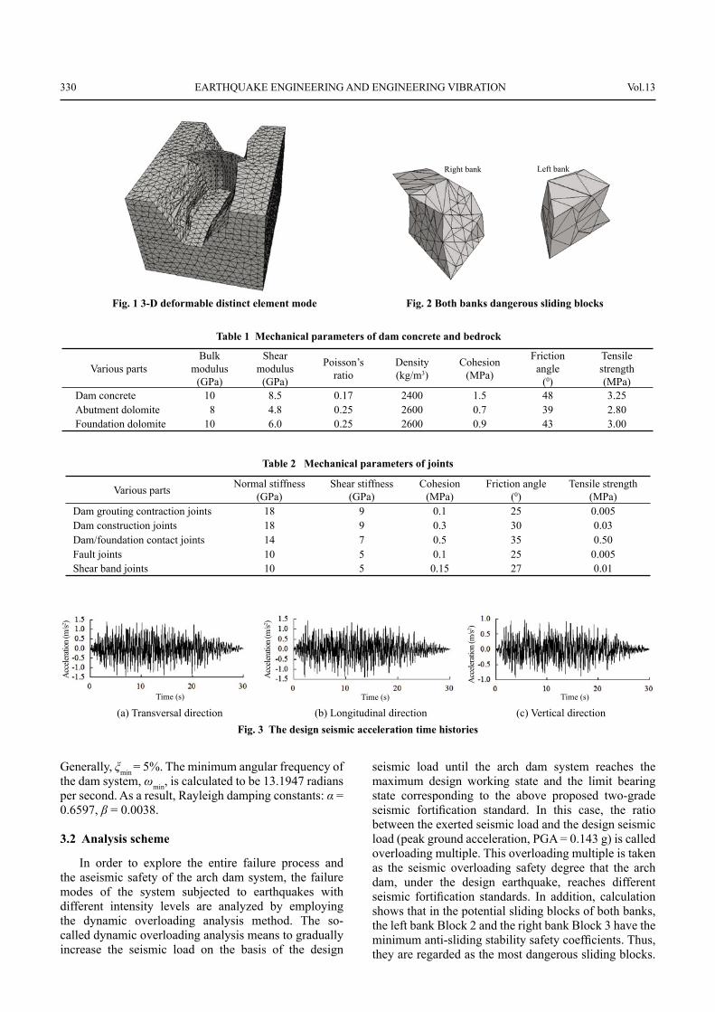
In this study, based on a Chinese national high arch dam located in a meizoseismal region, seismic research of arch dam system is carried out. The site terrain of the dam is a typical “U-shaped” river valley. The crest elevation of the arch dam is 1076.8 m, and the dam is about 106.8 m in the maximum height. The normal storage water level is 1071.0 m. In the various joints of abutment rock mass, the fault F5 and F27 are located in the left and right bank abutments, respectively. Angles between the two faults and the arch thrust directions are relatively smaller. Thus, the faults F5 and F27 form the side-slipping surfaces of abutment sliding wedges. In addition, fault F15 cuts across the abutments of both banks to form the tension crack surfaces of sliding wedges. The main shearing bands between the rock layers of the abutments of the both banks, whose occurrences and dip angles are very small, form the bottom sliding surfaces of the abutment sliding wedges at different elevations.
In the discrete element calculation model, the foundation rock, concrete dam and reservoir are fi nely simulated. In the foundation rock, the faults and shear bands between rock layers, playing the role of control for abutment stability, are created in the mode. In the concrete dam, the six vertical contraction joints, the dam/foundation contact joints and construction joints are modeled. The computational model domain is as follows: the scope of the abutments of both banks is taken to be 1.5 times the dam height. Along the dam axis, the dam foundation is extended 1.5 times and 2.0 times the dam height in the upstream and downstream directions, respectively. The bedrock depth below the dam body is taken as1.0 times the dam height. The 3-D
deformable distinct element model and dangerous sliding blocks on both banks are shown in Fig. 1 and Fig. 2, respectively. The Mohr-Coulomb material model is applied to the dam concrete and foundation rock. The Coulomb Slip model of 3DEC is employed to simulate the mechanical actions of the structural planes in the calculation. Mechanical parameter values of the dam concrete and foundation rocks are given in Table 1. Since the factors that affect the mechanical properties of structural planes are very complex, the values for the joints are taken from those suggested in 3DEC and the Code for Engineering Geological Investigation of Water Resources and Hydropower (GB50487-2008) (MOHURD, 2008), which are based on the results of experimental studies and statistical analysis. In addition, combined with site survey data of the dam system, mechanical parameter values of various joints are determined as shown in Table 2.
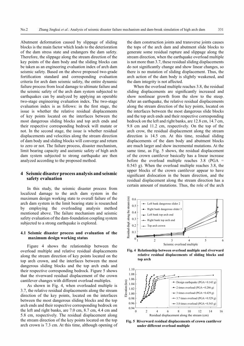
The dam seismic fortifi cation criterion is the basic seismic intensity VII on Chinese Seismic Intensity Scale (GB/T17742-2008) (SAOPRC, 2008). The horizontal peak acceleration of bedrock of the dam site with 10% transcendental probability in 50 years is 1.40 m/s2 taken from the research report of the Geology Institute of China Seismological Bureau. In the course of dynamic time-history analysis, the synthetic seismic acceleration waves in three spatial directions are adopted to input the seismic parameters by treating the design response spectrum at dam site as the target spectrum according to the Specifi cations for Seismic Design of Hydraulic Structures (DL 5073-2000) (MOPI, 2001). The characteristic period is 0.5 s. The vertical acceleration time history is obtained as 2/3 of the relative horizontal time history. The sampling interval of the time history is 0.02 s, and the duration is 30 s. The total calculation time is 32 s. Considering the infl uence of the characteristics of the frequency spectrum with different seismic inputs, the synthetic seismic waves with different spectral characteristics are generated to input the acceleration time histories. Figure 3 displays the design seismic acceleration time histories of bedrock of the dam site.
Considering the infl uence of infi nite foundation radiation damping, free fi eld boundaries are applied to the lateral boundaries of the model to simulate the infi nity domain and free fi eld conditions. Meanwhile, a viscous absorbing boundary is provided for the bottom of the model. First, acceleration time history is transformed into velocity time history, and then stress time history is obtained, which is input from the bottom of the model. The normal storage water level is considered. The hydrodynamic effects are approximated by Westergaard's added mass method. In this study, Rayleigh damping is adopted for seismic analysis of the arch dam system in the time domain. According to Biggs's recommendations on selecting the Rayleigh damping parameters, the minimum of the critical damping ratio ξmin = 2%–10% can obtain satisfactory results in the structure dynamic analysis (Biggs, 1964).
330 EARTHQUAKE ENGINEERING AND ENGINEERING VIBRATION Vol.13
Generally, ξmin = 5%. The minimum angular frequency of the dam system, ωmin, is calculated to be 13.1947 radians per second. As a result, Rayleigh damping constants: α = 0.6597, β = 0.0038.
3.2 Analysis scheme
In order to explore the entire failure process and the aseismic safety of the arch dam system, the failure modes of the system subjected to earthquakes with different intensity levels are analyzed by employing the dynamic overloading analysis method. The so-called dynamic overloading analysis means to gradually increase the seismic load on the basis of the design
seismic load until the arch dam system reaches the maximum design working state and the limit bearing state corresponding to the above proposed two-grade seismic fortifi cation standard. In this case, the ratio between the exerted seismic load and the design seismic load (peak ground acceleration, PGA = 0.143 g) is called overloading multiple. This overloading multiple is taken as the seismic overloading safety degree that the arch dam, under the design earthquake, reaches different seismic fortifi cation standards. In addition, calculation shows that in the potential sliding blocks of both banks, the left bank Block 2 and the right bank Block 3 have the minimum anti-sliding stability safety coeffi cients. Thus, they are regarded as the most dangerous sliding blocks.
Table 1 Mechanical parameters of dam concrete and bedrock
Various partsBulk
modulus(GPa)
Shear modulus
(GPa)
Poisson’s ratio
Density(kg/m3)
Cohesion (MPa)
Frictionangle
(0)
Tensile strength(MPa)
Dam concrete 10 8.5 0.17 2400 1.5 48 3.25Abutment dolomite 8 4.8 0.25 2600 0.7 39 2.80Foundation dolomite 10 6.0 0.25 2600 0.9 43 3.00
Table 2 Mechanical parameters of joints
Various parts Normal stiffness (GPa)
Shear stiffness (GPa)
Cohesion (MPa)
Friction angle (0)
Tensile strength (MPa)
Dam grouting contraction joints 18 9 0.1 25 0.005Dam construction joints 18 9 0.3 30 0.03Dam/foundation contact joints 14 7 0.5 35 0.50Fault joints 10 5 0.1 25 0.005Shear band joints 10 5 0.15 27 0.01
Fig. 1 3-D deformable distinct element mode Fig. 2 Both banks dangerous sliding blocks
(a) Transversal direction (b) Longitudinal direction (c) Vertical directionFig. 3 The design seismic acceleration time histories
Right bank Left bank
Time (s) Time (s) Time (s)
Acc
elera
tion (
m/s2 )
Acc
elera
tion (
m/s2 )
Acc
elera
tion (
m/s2 )
No.2 Zhang Jingkui et al.: Analysis of seismic disaster failure mechanism and dam-break simulation of high arch dam 331
Abutment deformation caused by slippage of sliding blocks is the main factor which leads to the deterioration of the dam stress state and endangers the dam safety. Therefore, the slippage along the stream direction of the key points of the dam body and the sliding blocks can be taken as an engineering evaluation index of arch dam seismic safety. Based on the above proposed two-grade fortifi cation standard and corresponding evaluation criteria for arch dam seismic safety, the entire dynamic failure process from local damage to ultimate failure and the seismic safety of the arch dam system subjected to earthquakes can by analyzed by applying an operable two-stage engineering evaluation index. The two-stage evaluation index is as follows: in the fi rst stage, the issue is whether the relative residual displacements of key points located on the interfaces between the most dangerous sliding blocks and top arch ends and their respective corresponding bedrock will mutate or not. In the second stage, the issue is whether residual displacements and velocities along the stream direction of dam body and sliding blocks will converge and return to zero or not. The failure process, disaster mechanism, limit bearing capacity and aseismic safety of high arch dam system subjected to strong earthquake are then analyzed according to the proposed method.
4 Seismic disaster process analysis and seismic safety evaluation
In this study, the seismic disaster process from localized damage to the arch dam system in the maximum design working state to overall failure of the arch dam system in the limit bearing state is researched by employing the overloading analysis method mentioned above. The failure mechanism and seismic safety evaluation of the dam-foundation coupling system subjected to a strong earthquake is explored.
4.1 Seismic disaster process and evaluation of the maximum design working status
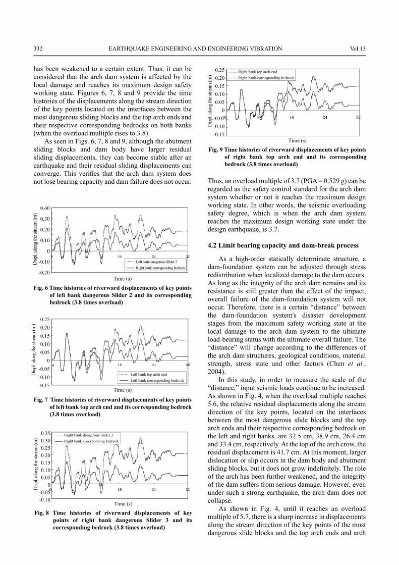
Figure 4 shows the relationship between the overload multiple and relative residual displacements along the stream direction of key points located on the top arch crown, and the interfaces between the most dangerous sliding blocks and the top arch ends and their respective corresponding bedrock. Figure 5 shows that the riverward residual displacement of the crown cantilever changes with different overload multiples.
As shown in Fig. 4, when overloaded multiple is 3.7, the relative residual displacements along the stream direction of the key points, located on the interfaces between the most dangerous sliding blocks and the top arch ends and their respective corresponding bedrock on the left and right banks, are 7.0 cm, 8.7 cm, 4.4 cm and 5.8 cm, respectively. The residual displacement along the stream direction of the key points located on the top arch crown is 7.3 cm. At this time, although opening of
the dam construction joints and transverse joints causes the tops of the arch dam and abutment slide blocks to generate some residual rupture and slippage along the stream direction, when the earthquake overload multiple is not more than 3.7, these residual sliding displacements do not signifi cantly change and show linear changes, so there is no mutation of sliding displacement. Thus, the arch action of the dam body is slightly weakened, and the dam integrity is not affected.
When the overload multiple reaches 3.8, the residual sliding displacements are signifi cantly increased and show nonlinear growth from the slow to the steep. After an earthquake, the relative residual displacements along the stream direction of the key points, located on the interfaces between the most dangerous slide blocks and the top arch ends and their respective corresponding bedrock on the left and right banks, are 12.8 cm, 14.7 cm, 9.8 cm and 11.2 cm, respectively. On the top of the arch crow, the residual displacement along the stream direction is 14.5 cm. At this time, residual sliding displacements of the dam body and abutment blocks are much larger and show incremental mutations. At the same time, as Fig. 5 shows, the residual displacement of the crown cantilever basically has a linear increase before the overload multiple reaches 3.8 (PGA = 0.543 g). When the overload multiple reaches 3.8, the upper blocks of the crown cantilever appear to have signifi cant dislocation in the beam direction, and the residual displacement along the stream direction has a certain amount of mutations. Thus, the role of the arch
Fig. 4 Relationship between overload multiple and riverward relative residual displacements of sliding blocks and top arch
0.6
0.5
0.4
0.3
0.2
0.1
0 1 2 3 4 5 6Seismic overload multiple
Resid
ual d
ispl. a
long
the s
tream
(m)
Left bank dangerous slider 2
Right bank dangerous slider 3
Left bank top arch end
Right bank top arch end
Top arch crown
Fig. 5 Riverward residual displacements of crown cantilever under different overload multiple
1.101.081.061.041.021.000.980.960.94
0 2 4 6 8 10 12 14 16Residual displacement along the stream (cm)
Elev
ation
(km
)
Left bank dangerous slider 2
Right bank dangerous slider 3
Left bank top arch end
Right bank top arch end
Top arch crown
Design earthquake (PGA = 0.143 g)
2 times overload (PGA = 0.286 g)
3 times overload (PGA = 0.429 g)
3.7 times overload (PGA = 0.529 g)
3.8 times overload (PGA = 0.543 g)
332 EARTHQUAKE ENGINEERING AND ENGINEERING VIBRATION Vol.13
has been weakened to a certain extent. Thus, it can be considered that the arch dam system is affected by the local damage and reaches its maximum design safety working state. Figures 6, 7, 8 and 9 provide the time histories of the displacements along the stream direction of the key points located on the interfaces between the most dangerous sliding blocks and the top arch ends and their respective corresponding bedrocks on both banks (when the overload multiple rises to 3.8).
As seen in Figs. 6, 7, 8 and 9, although the abutment sliding blocks and dam body have larger residual sliding displacements, they can become stable after an earthquake and their residual sliding displacements can converge. This verifi es that the arch dam system does not lose bearing capacity and dam failure does not occur. Thus, an overload multiple of 3.7 (PGA = 0.529 g) can be
regarded as the safety control standard for the arch dam system whether or not it reaches the maximum design working state. In other words, the seismic overloading safety degree, which is when the arch dam system reaches the maximum design working state under the design earthquake, is 3.7.
4.2 Limit bearing capacity and dam-break process
As a high-order statically determinate structure, a dam-foundation system can be adjusted through stress redistribution when localized damage to the dam occurs. As long as the integrity of the arch dam remains and its resistance is still greater than the effect of the impact, overall failure of the dam-foundation system will not occur. Therefore, there is a certain “distance” between the dam-foundation system's disaster development stages from the maximum safety working state at the local damage to the arch dam system to the ultimate load-bearing status with the ultimate overall failure. The “distance” will change according to the differences of the arch dam structures, geological conditions, material strength, stress state and other factors (Chen et al., 2004).
In this study, in order to measure the scale of the “distance,” input seismic loads continue to be increased. As shown in Fig. 4, when the overload multiple reaches 5.6, the relative residual displacements along the stream direction of the key points, located on the interfaces between the most dangerous slide blocks and the top arch ends and their respective corresponding bedrock on the left and right banks, are 32.5 cm, 38.9 cm, 26.4 cm and 33.4 cm, respectively. At the top of the arch crow, the residual displacement is 41.7 cm. At this moment, larger dislocation or slip occurs in the dam body and abutment sliding blocks, but it does not grow indefi nitely. The role of the arch has been further weakened, and the integrity of the dam suffers from serious damage. However, even under such a strong earthquake, the arch dam does not collapse.
As shown in Fig. 4, until it reaches an overload multiple of 5.7, there is a sharp increase in displacements along the stream direction of the key points of the most dangerous slide blocks and the top arch ends and arch
Fig. 6 Time histories of riverward displacements of key points of left bank dangerous Slider 2 and its corresponding bedrock (3.8 times overload)
0.40
0.30
0.20
0.10
0
-0.10
-0.20Time (s)
Disp
l. alo
ng th
e stre
am (m
)
Left bank dangerous Slider 2Right bank corresponding bedrock
Fig. 7 Time histories of riverward displacements of key points of left bank top arch end and its corresponding bedrock (3.8 times overload)
0.250.200.150.100.05
0-0.05-0.10-0.15
Time (s)
Disp
l. alo
ng th
e stre
am (m
)
Left bank top arch endLeft bank corresponding bedrock
Fig. 8 Time histories of riverward displacements of key points of right bank dangerous Slider 3 and its corresponding bedrock (3.8 times overload)
0.350.300.250.200.150.100.05
0-0.05-0.10
Time (s)
Disp
l. alo
ng th
e stre
am (m
)
Right bank dangerous Slider 3Right bank coresponding bedrock
Fig. 9 Time histories of riverward displacements of key points of right bank top arch end and its corresponding bedrock (3.8 times overload)
0.250.200.150.100.05
0-0.05-0.10-0.15
Time (s)
Disp
l. alo
ng th
e stre
am (m
)
Right bank top arch endRight bank corresponding bedrock
No.2 Zhang Jingkui et al.: Analysis of seismic disaster failure mechanism and dam-break simulation of high arch dam 333
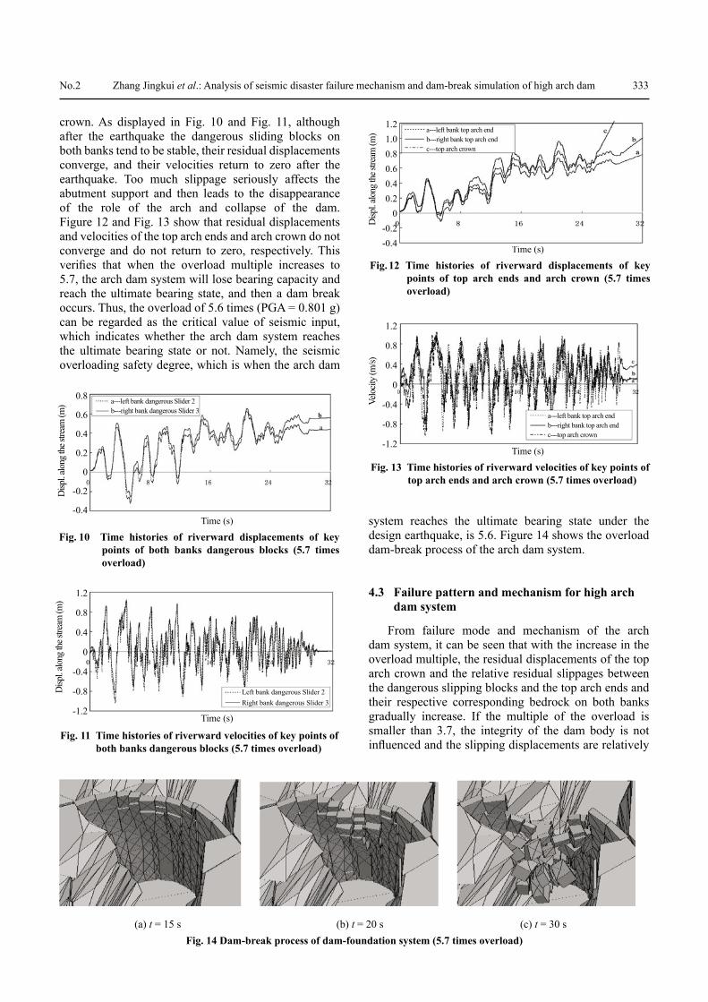
crown. As displayed in Fig. 10 and Fig. 11, although after the earthquake the dangerous sliding blocks on both banks tend to be stable, their residual displacements converge, and their velocities return to zero after the earthquake. Too much slippage seriously affects the abutment support and then leads to the disappearance of the role of the arch and collapse of the dam. Figure 12 and Fig. 13 show that residual displacements and velocities of the top arch ends and arch crown do not converge and do not return to zero, respectively. This verifi es that when the overload multiple increases to 5.7, the arch dam system will lose bearing capacity and reach the ultimate bearing state, and then a dam break occurs. Thus, the overload of 5.6 times (PGA = 0.801 g) can be regarded as the critical value of seismic input, which indicates whether the arch dam system reaches the ultimate bearing state or not. Namely, the seismic overloading safety degree, which is when the arch dam
system reaches the ultimate bearing state under the design earthquake, is 5.6. Figure 14 shows the overload dam-break process of the arch dam system.
4.3 Failure pattern and mechanism for high arch dam system
From failure mode and mechanism of the arch dam system, it can be seen that with the increase in the overload multiple, the residual displacements of the top arch crown and the relative residual slippages between the dangerous slipping blocks and the top arch ends and their respective corresponding bedrock on both banks gradually increase. If the multiple of the overload is smaller than 3.7, the integrity of the dam body is not infl uenced and the slipping displacements are relatively
Fig. 10 Time histories of riverward displacements of key points of both banks dangerous blocks (5.7 times overload)
0.8
0.6
0.4
0.2
0
-0.2
-0.4Time (s)
Disp
l. alo
ng th
e stre
am (m
) a---left bank dangerous Slider 2b---right bank dangerous Slider 3
Fig. 11 Time histories of riverward velocities of key points of both banks dangerous blocks (5.7 times overload)
1.2
0.8
0.4
0
-0.4
-0.8
-1.2Time (s)
Disp
l. alo
ng th
e stre
am (m
)
Left bank dangerous Slider 2Right bank dangerous Slider 3
Fig. 12 Time histories of riverward displacements of key points of top arch ends and arch crown (5.7 times overload)
Time (s)
Disp
l. alo
ng th
e stre
am (m
)
Right bank dangerous slider 3Right bank coresponding bedrock
1.21.00.80.60.40.2
0-0.2-0.4
a---left bank top arch endb---right bank top arch endc---top arch crown
Fig. 13 Time histories of riverward velocities of key points of top arch ends and arch crown (5.7 times overload)
Time (s)
Velo
city (
m/s)
1.2
0.8
0.4
0
-0.4
-0.8
-1.2
a---left bank top arch endb---right bank top arch endc---top arch crown
(a) t = 15 s (b) t = 20 s (c) t = 30 sFig. 14 Dam-break process of dam-foundation system (5.7 times overload)
334 EARTHQUAKE ENGINEERING AND ENGINEERING VIBRATION Vol.13
small, the change tendency shows a linear increase. When the multiple of the overload rises to 3.8, the increase of the residual slipping displacements become prominent, and a certain amount of displacement mutations occur. The slippages along the stream direction of the sliding blocks on the right bank are larger than those on the left bank, and the differences between them become more obvious as the over-load times increase. Although the relative residual displacements along the stream direction of the arch ends and abutment sliding blocks on both banks are relatively larger, they tend to be stable and do not continue to grow after the earthquake, and the arch dam system is still safe. During this time, relatively large dislocation and slipping of the upper dam body causes the role of the arch to be somewhat weakened. Thus, it can be concluded that the arch dam system suffers from local damage to its integrity and reaches the maximum safety working state.
With a further increase in earthquake load, the residual slipping displacements mentioned above have a sharper growth. When the times of overload rise to 5.7, the growth is further accelerated. Despite the larger slippages, the sliding blocks of both banks fi nally tend to be stable after the earthquake. However, the larger slippages of the sliding blocks cause the supports of dam body to be freed. Then the arch action of dam body disappears. In this case, the slipping displacements along the stream direction continue to increase. The arch dam system then reaches the ultimate bearing state and breaks. The entire dam-break process shows that the upper arch crown has large slippages and then begins to fall to the downstream side fi rst. Following this, the adjacent dam structures successively fail. Eventually, the entire dam collapses.
5 Conclusions
The following conclusions can be drawn from this study:
(1) A 3-D deformation discrete element method is used to simulate large deformations both with material nonlinear and contact nonlinear characteristics. The method enables failure simulation and stability analysis of the dam-foundation coupling system.
(2) The nonlinear dynamic analysis model is constructed to refl ect dislocation and slipping of potential sliding blocks on the abutments of both banks and the instability process of the structure. Safety evaluation criterion is proposed, which can determine the maximum design working state with localized damage to the dam-foundation system and the ultimate limit bearing status with overall failure. Based on a Chinese national high arch dam, the earthquake disaster process is investigated. The results are as follows: under the design earthquake (PGA = 0.143 g), the seismic overloading safety degrees are 3.7 and 5.6, when the arch dam system reaches the maximum design working state and the ultimate limit bearing state, respectively.
(3) From the failure mode of the arch dam system researched in this study, it can be seen that the larger slippages of abutment rocks that caused the deformation of the arch dam axis was too large to meet the requirements of the arch axis equation, and the arch role was greatly weakened. Following this, the crown cantilever began to be gradually undermined, and eventually the entire dam break occurred. Many studies show that one of the main failure modes of the arch dam system is the sliding and instability of abutment rock mass, that eventually results in dam failure. Therefore, for a high arch dam, a complex three-dimensional shell structure that can transfer a large amount of water pressure to both sides of the rock masses due to factors such as dam body shape, both sides valley shape, geological structure of rock masses and earthquake input parameters, etc., will affect failure mode of arch dam system. Thus, the disaster mechanism of a high arch dam is very complex. This study should be regarded as a preliminary exploratory work, and should be combined with methods currently used in engineering practice in China in a future study.
Acknowledgement
We are very grateful to Professor Qiao Pizhong, Washington State University, for providing constructive suggestions. We would also like to express our gratitude to the anonymous reviewers for their many helpful comments and suggestions. This work was supported by the National Natural Science Foundation of China (Grant No. 90510017).
References
Bardet JP and Soctt RF (1985), “Seismic Stabiliy of Fractured Rock Masses with the Distinct Element Method,” 26th US Symposium on Rock Mechanics, Rapid Ciy. SD: Balkema A A. Rotterdam Neth, pp. 26–28.Bathe KJ (1997), “A Solution Method for Planar and Axisymmetric Contact Problems,” Int. J. Num, Meth in Eng, 21: 65–88.Bathe KJ and Bouzinov PA (1997), “On the Constraint Function Method for Contact Problems,” Computers and Structures, 64(5): 1069–1085.Biggs JM (1964), Introduction to Structural Dynamics, New York: McGraw-Hill.Chen Houqun, Zhang Boyan and Tu Jin (2004), “Study on Dynamic Stability of Arch Dam Abutment,” Journal of Hydroelectric Engineering, 23(6): 40–44. (in Chinese)Cundall PA (1971a), “The Measurement and Analysis of Acceleration in Rock Slopes,” PhD Dissertation, London: University of London Imerial College of Science and Technology.
No.2 Zhang Jingkui et al.: Analysis of seismic disaster failure mechanism and dam-break simulation of high arch dam 335
Cundall PA (1971b), “A Computer Model for Simulating Progressive Large Scale Movement in Block Rock System,” Symposium ISRM,Proc 2: 129–136.Hou Yanli (2005), “A Coupling Rupture Model of Distinct Element and Fracture Mechanics for Concrete Dam-Foundations,” Beijing: Tsinghua University, PhD Dissertation. (in Chinese)ITASCA Consulting Group Inc (2003), Three-dimensional Distinct Element Code, Version 3.0 User’s manual, USA.Lin Gao (2006), “Developing Tendency of the Seismic Safety Evaluation of Large Concrete Dams,” Journal of Disaster Prevention and Mitigation Engineering, 26(01): 1–12. (in Chinese)Lysmer J and Kuhlmeyer RL (1969), “Finite Dynamic Model for Infi nite Media,” Journal of Engineering Mechanics Division, ASCE, 95(4): 759–877.Lysmer J and Kuhlmeyer RL (1973), “Finite Element Method Accuracy for Wave Propagation Problems,” J. soil Mech&Foundations Div, ASCE, 99: 421–427.Ministry of Housing and Urban-Rural Development of the People’s Republic of China (2008), Code for Engineering Geological Investigation of Water Resources and Hydropower (GB50487-2008),” China Planning Press. (in Chinese)Ministry of Power Industry of the People’s Republic of China (2001), Specifi cations for Seismic Design of Hydraulic Structures (DL5073-2000), China Waterpower Press. (in Chinese)Pekau OA and Cui YZ (2004), “Failure Analysis of Fractured Dams during Earthquakes by DEM,” Engineering Structures, 26(10): 1483–1502.
Sawamoto Y and Tsubota H et al. (1998), “Analytical Studies on Local Damage to Reinforced Concrete Structures under Impact Loading by Discrete Element Method,” Nuclear Engineering and Design, 179: 157–177.Standardization Administration of the People’s Republic of China (2008), Chinese Seismic Intensity Scale (GB/T17742-2008), China Standard Press.Tu Jin and Chang Houqun (2006), “Seismic Safety of High Arch Dam in Xiaowan Project under the Action of Earthquakes with Different Exceeding Probabilities,” Journal of Hydraulic Engineering, 37(03): 278–285. (in Chinese)Zhang Boyan and Chen Houqun (2001), “Analysis on Abutment Aseismatic Stability by Using Finite Element and Rigid Body Limit Equilibrium Method,” Chinese Journal of Rock Mechanics and Engineering, 20(5): 665–670. (in Chinese)Zhang Chuhan (2008), “Discrete-contact-fracture Analysis of Rock and Concrete,” Chinese Journal of Rock Mechanics and Engineering, 27(02): 217–235. (in Chinese)Zhang Chuhan and Pekau OA, Jin Feng and Wang Guanglun (1997), “Application of Distinct Element Method in Dynamic Analysis of High Rock Slopes and Blocky Structures,” Soil Dynamics and Earthquake Engineering, 16(6): 385–394.Zhang Jingkui and Zhang Liaojun (2013), “3-D Seismic Response Analysis of High Core Rockfi ll Dam,” The Arabian Journal for Science and Engineering, 38(4):839–848.