Embed Size (px)
Citation preview

Analysis of ResultsDIN 51350 - 4-Ball Apparatus
Extracts of Test Report
Lubeck University, Germany

The 4-ball apparatus
The Shell Four Ball Tester (FBT) is a testing device standardized in DIN 51 350 Part 1 and is used to determine welding and metal loads (DIN 51 350 Part 2 and 3) as well as different friction and wear characteristics of lubricants (DIN 51 350 Part 4 and 5).
The standard test consists of a rotating ball of a ball bearing being pressed onto three similar butimmobile balls while applying a load.
This testing device is especially common in the lubricant industry where it is used for routine product development and quality control testing. The friction torque can be recorded continuously. Wear is determined by optically measuring the formed calotte (the worn depression area).
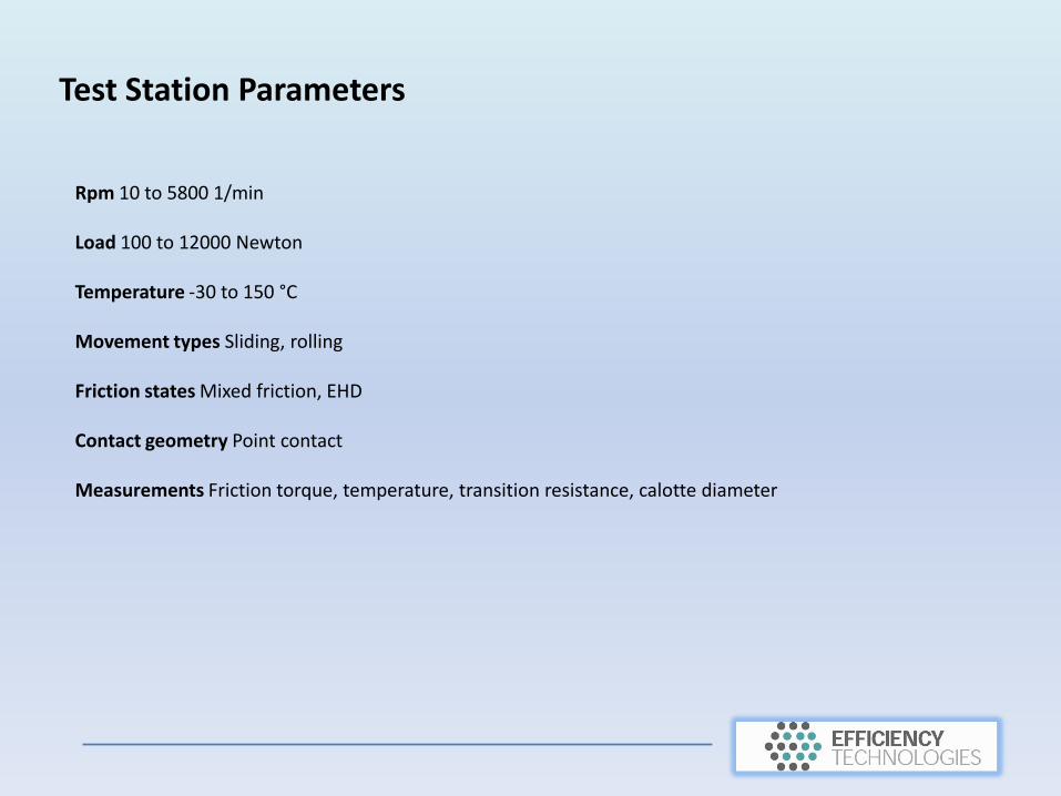
Test Station Parameters
Rpm 10 to 5800 1/min
Load 100 to 12000 Newton
Temperature -30 to 150 °C
Movement types Sliding, rolling
Friction states Mixed friction, EHD
Contact geometry Point contact
Measurements Friction torque, temperature, transition resistance, calotte diameter

Examination
The test examined wear protection product "NanoVit Motor Renovator"according to DIN 51350. The aim was to investigate the wear-reducing effect by applying constant and dynamically increasing test loads. The tests wereperformed on a four ball tester and a Universal tribometer.

Test results for Part 3, DIN 51350 Determination of Wearing Characteristics
Force load [N] Average coefficient of friction [μ]
Wear scar diameter[mm]
Minimum wearaccording to DIN [mm]
150 N μ 0,067 0,29 mm 0,22 mm
300 N μ 0,053 0,38 mm 0,27 mm

Test results for Part 3, DIN 51350 Determination of Wearing Characteristics
The shape of the curve of wear volume at the beginning of the test is in an initial phase, in which the wear volume increases. Then the curve flattens and increases almost linearly with much lower gradient. For the test with 150 N the final wear volume is 5.82 * 10-5 mm3.
Wear volume – DIN 51 350 - Part 3
Wear Volume – Attempt 1
Time [sec]
Wea
r vo
lum
e [m
m3]

Test results for Part 4, DIN 51350 Determination of Welding Load
The test run was started with a test load of 2000 N moving up to 4800 N with step increases of 200 N. When loads reach a weld point the test rig engine will stop due to welding of the balls under test. This point will be reached at a shorter or longer time depending on the lubrication properties.
The welding point of the balls was not reached during the test even at the full load. Therefore, the test equipment maximum of 12,000 N was as high as the equipment would allow testing. This is unusual, welding in 10W40 oil would be expected to occur at considerably lower forces than this.
Since the test actually concerns testing product additives for a 10W40 mineral oil, a welding strength between 3200 N to 3400 N would be appropriate. The test demonstrated considerably greater welding strength.

Test results for Part 4, DIN 51350Determination of Welding Load
Conclusion: An short friction increase is expected at the start on all the curves, as is characteristic of frictional processes. After the short increase, a constant friction coefficient of 0.08 was measured at all test loads, except at 3400 N. As of 3400 N the friction coefficient increases. However, welding of the Balls could not be established.
Friction coefficient at 2000 – 3400 N – DIN 31 530 – Part 4
Time [s]

Test results for Part 4, DIN 51350At maximum power load of 12000 N
Friction coefficient at 3600 –12000 N – DIN 31 530 – Part 4
Time [s]
Conclusion: The welding of the balls was not achieved even at 12000 N (1.2 tons spot fixing load). The coefficient of friction at this force was μ 0.12.
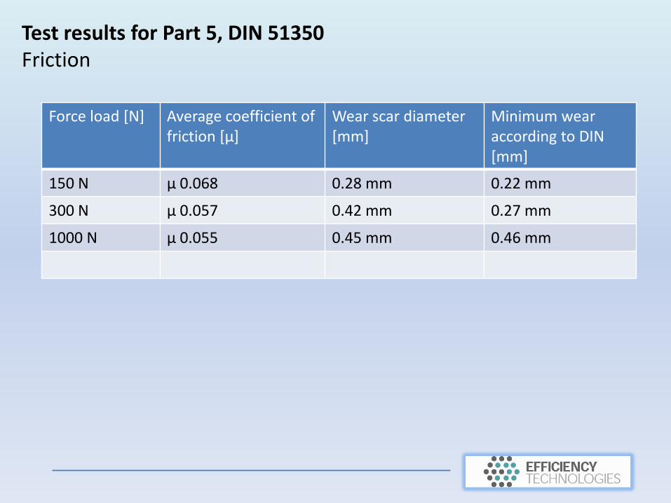
Test results for Part 5, DIN 51350 Friction
Force load [N] Average coefficient of friction [μ]
Wear scar diameter[mm]
Minimum wearaccording to DIN [mm]
150 N μ 0.068 0.28 mm 0.22 mm
300 N μ 0.057 0.42 mm 0.27 mm
1000 N μ 0.055 0.45 mm 0.46 mm

Test results for Part 5, DIN 51350 Wear Volume
Wear volume – DIN 51 350 – Part 5
Time [sec]
Wea
r vo
lum
e [m
m3]
At the beginning of the test run, the curve at 150 N and 300 N has the expected initial phase. After 1 hour the curve flattens and reaches a value of 3.8 * 10-5 mm3. During a 1 minute test period at 1000 N, the wear volume steadily increases to the end of the test run when the final wear volume is 2.2 * 10-5 mm3. Friction increases upto approximately 20 minutes. After 60 min measured wear is an almost constant value (wear rate near 0).
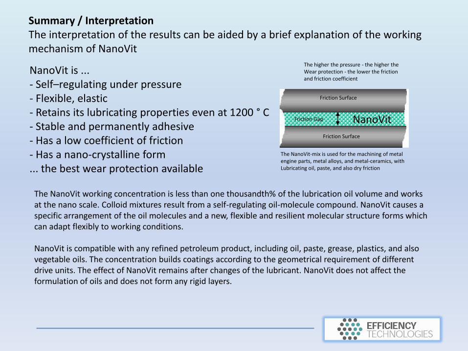
Summary / InterpretationThe interpretation of the results can be aided by a brief explanation of the working mechanism of NanoVit
NanoVit is ...- Self–regulating under pressure- Flexible, elastic- Retains its lubricating properties even at 1200 ° C - Stable and permanently adhesive- Has a low coefficient of friction- Has a nano-crystalline form... the best wear protection available
The NanoVit working concentration is less than one thousandth% of the lubrication oil volume and works at the nano scale. Colloid mixtures result from a self-regulating oil-molecule compound. NanoVit causes a specific arrangement of the oil molecules and a new, flexible and resilient molecular structure forms which can adapt flexibly to working conditions.
NanoVit is compatible with any refined petroleum product, including oil, paste, grease, plastics, and also vegetable oils. The concentration builds coatings according to the geometrical requirement of different drive units. The effect of NanoVit remains after changes of the lubricant. NanoVit does not affect the formulation of oils and does not form any rigid layers.
The higher the pressure - the higher theWear protection - the lower the frictionand friction coefficient
Friction Gap
The NanoVit-mix is used for the machining of metal engine parts, metal alloys, and metal-ceramics, withLubricating oil, paste, and also dry friction
Friction Surface
Friction Surface
NanoVit

Summary / Interpretation
1. The active components in the NanoVit Motor Renovator additized 10W40 oil have expected weld strength between 3200 N to 3400 N.
Interestingly, with the NanoVit oil the 4-ball apparatus maximum force of 12,000 N was applied without welding taking place and a low coefficient of friction μ of 0.12 was also measured at this force.
The working concentration was 1 thousandth% share of NanoVit to the oil.
2. In a comparison of the friction force for increasing load (from 3400 N to 12000 N), it is clear that the higher the pressure, the lower the coefficient of friction.
As per manufacturer data the wear protection is constructed and acts optimally under load, which is shown clearly in Fig. 9 below
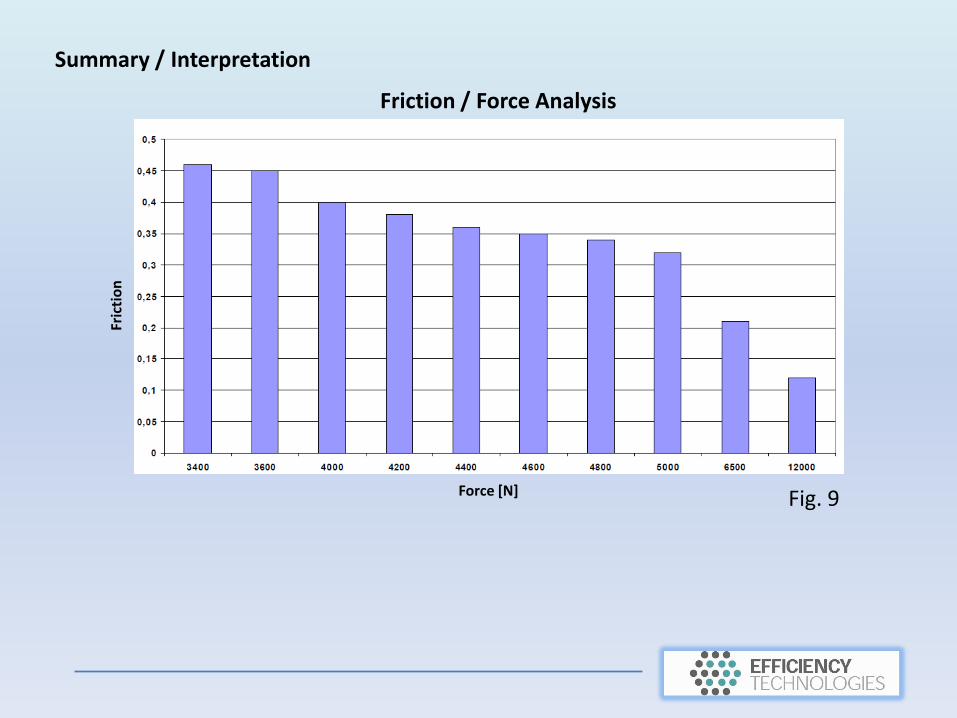
Friction / Force AnalysisFr
icti
on
Force [N] Fig. 9
Summary / Interpretation

Summary / Interpretation
3. In the comparison of the friction values with a rising force load of 300 N to 12000 N, at 3400 N a clear rise of the friction values is registered. However with rising force load the friction value decreases and the resultant wear protection is increased.
Between 3200 N to 3400 N the actual property is typical for the wear protection and welding strength of oil of type 10W40. In fig. 10 below it is to be assumed the limit values of the oil were reached here (3400N).
At 3400 N NanoVit, under pressure and temperature, develops in the friction zones as a flexible, firmly adhering layer. It is assumed here that the layer provided the wear effect shown from 3400 N to 12000 N, which is beyond the normal limits of the 10W40 oil.
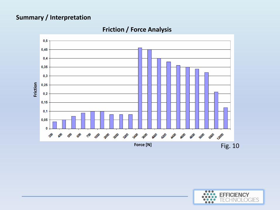
Friction / Force AnalysisFr
icti
on
Force [N] Fig. 10
Summary / Interpretation