Embed Size (px)
Citation preview
Analysis of Phase Space Matching with RF Quadrupole
D.L.Rubin
December 2, 2015
1 Introduction
Young-Im Kim, Seung Pyo Chang, Martin Gaisser, Uiryeol Lee, Soohyung Lee, and Yannis Se-mertzidis propose to superimpose an RF voltage on an electrostatic quadrupole in the g-2 ring tomatch the phase space of the injected muon distribution to the twiss parameters characteristic ofthe storage ring. The goal is to effect matching of the phase space by modulation of the focallength of a single ring quad on each of the first 150-200 turns. A tracking simulation, based onthe BMAD model of the g-2 ring is used to test the concept, and in particular the effect of thenonlinearities of the quadrupoles, the finite energy and temporal spread of the muon distribution,and the displacement of the centroid of the distribution.
2 Phase Space Matching
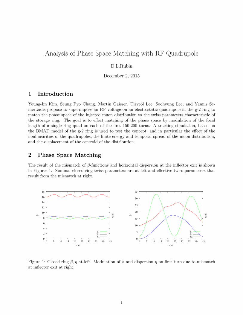
The result of the mismatch of β-functions and horizontal dispersion at the inflector exit is shownin Figures 1. Nominal closed ring twiss parameters are at left and effective twiss parameters thatresult from the mismatch at right.
0
2
4
6
8
10
12
14
16
18
0 5 10 15 20 25 30 35 40 45
β
η[m
]
s[m]
βxβyηx 0
5
10
15
20
25
30
35
0 5 10 15 20 25 30 35 40 45
β
η[m
]
s[m]
βxβyηx
Figure 1: Closed ring β, η at left. Modulation of β and dispersion η on first turn due to mismatchat inflector exit at right.
1
The β-error of the magic momentum muon distribution that results from mistmatch of inflectorinto ring, propagates at twice the betatron frequency, as in Equation 1.
∆β(s)x.y = Ax,y cos(2(2πQx,y) + φx,y) (1)
The proposal of Kim et al. is to similarly modulate the voltage of a quadrupole, that is at twicethe respective horizontal and vertical betatron frequencies. The RF voltage applied to one of thering quadrupoles, is (Equation 2)
V = Ax cos(2ωxt+ φx) +Ay cos(2ωyt+ φy) (2)
where ωx,y = 2πfrev(2Qx,y) and frev is the cyclotron frequency of the magic momentum muon, andQx,y the horizontal or vertical betatron tune.
3 Horizontal
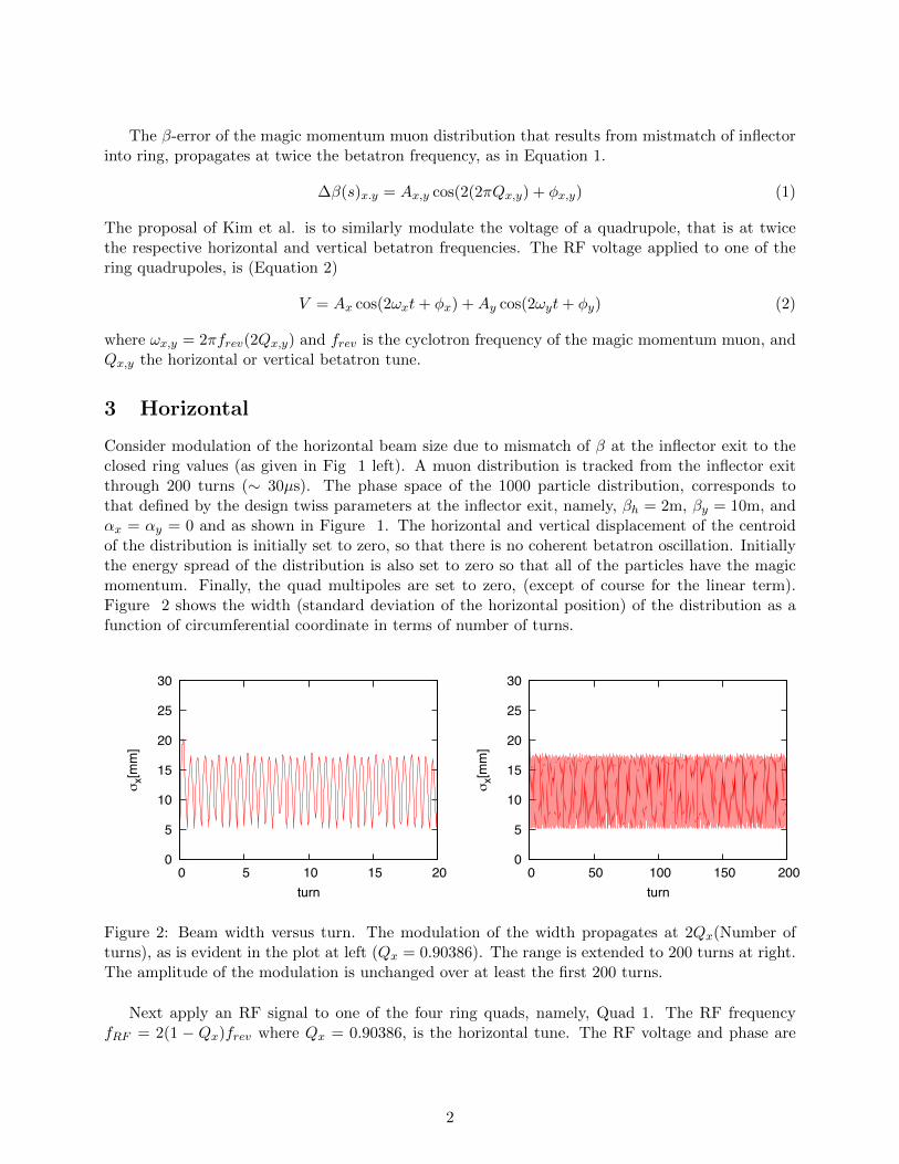
Consider modulation of the horizontal beam size due to mismatch of β at the inflector exit to theclosed ring values (as given in Fig 1 left). A muon distribution is tracked from the inflector exitthrough 200 turns (∼ 30µs). The phase space of the 1000 particle distribution, corresponds tothat defined by the design twiss parameters at the inflector exit, namely, βh = 2m, βy = 10m, andαx = αy = 0 and as shown in Figure 1. The horizontal and vertical displacement of the centroidof the distribution is initially set to zero, so that there is no coherent betatron oscillation. Initiallythe energy spread of the distribution is also set to zero so that all of the particles have the magicmomentum. Finally, the quad multipoles are set to zero, (except of course for the linear term).Figure 2 shows the width (standard deviation of the horizontal position) of the distribution as afunction of circumferential coordinate in terms of number of turns.
0
5
10
15
20
25
30
0 5 10 15 20
σx[m
m]
turn
0
5
10
15
20
25
30
0 50 100 150 200
σx[m
m]
turn
Figure 2: Beam width versus turn. The modulation of the width propagates at 2Qx(Number ofturns), as is evident in the plot at left (Qx = 0.90386). The range is extended to 200 turns at right.The amplitude of the modulation is unchanged over at least the first 200 turns.
Next apply an RF signal to one of the four ring quads, namely, Quad 1. The RF frequencyfRF = 2(1 − Qx)frev where Qx = 0.90386, is the horizontal tune. The RF voltage and phase are
2
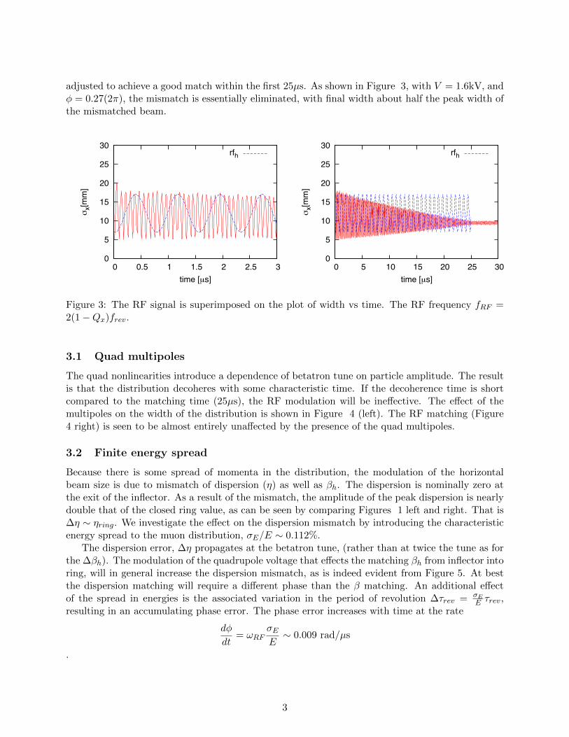
adjusted to achieve a good match within the first 25µs. As shown in Figure 3, with V = 1.6kV, andφ = 0.27(2π), the mismatch is essentially eliminated, with final width about half the peak width ofthe mismatched beam.
0
5
10
15
20
25
30
0 0.5 1 1.5 2 2.5 3
σx[m
m]
time [µs]
rfh
0
5
10
15
20
25
30
0 5 10 15 20 25 30
σx[m
m]
time [µs]
rfh
Figure 3: The RF signal is superimposed on the plot of width vs time. The RF frequency fRF =2(1 −Qx)frev.
3.1 Quad multipoles
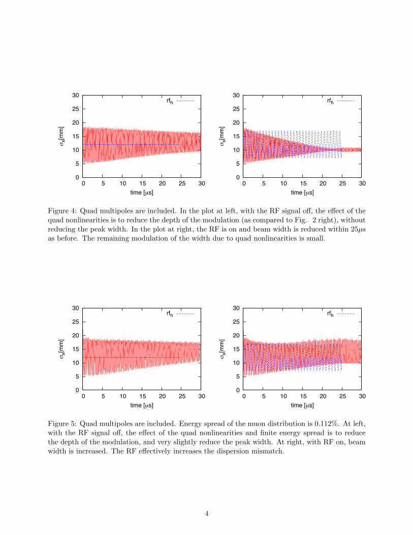
The quad nonlinearities introduce a dependence of betatron tune on particle amplitude. The resultis that the distribution decoheres with some characteristic time. If the decoherence time is shortcompared to the matching time (25µs), the RF modulation will be ineffective. The effect of themultipoles on the width of the distribution is shown in Figure 4 (left). The RF matching (Figure4 right) is seen to be almost entirely unaffected by the presence of the quad multipoles.
3.2 Finite energy spread
Because there is some spread of momenta in the distribution, the modulation of the horizontalbeam size is due to mismatch of dispersion (η) as well as βh. The dispersion is nominally zero atthe exit of the inflector. As a result of the mismatch, the amplitude of the peak dispersion is nearlydouble that of the closed ring value, as can be seen by comparing Figures 1 left and right. That is∆η ∼ ηring. We investigate the effect on the dispersion mismatch by introducing the characteristicenergy spread to the muon distribution, σE/E ∼ 0.112%.
The dispersion error, ∆η propagates at the betatron tune, (rather than at twice the tune as forthe ∆βh). The modulation of the quadrupole voltage that effects the matching βh from inflector intoring, will in general increase the dispersion mismatch, as is indeed evident from Figure 5. At bestthe dispersion matching will require a different phase than the β matching. An additional effectof the spread in energies is the associated variation in the period of revolution ∆τrev = σE
E τrev,resulting in an accumulating phase error. The phase error increases with time at the rate
dφ
dt= ωRF
σEE
∼ 0.009 rad/µs
.
3
0
5
10
15
20
25
30
0 5 10 15 20 25 30
σx[m
m]
time [µs]
rfh
0
5
10
15
20
25
30
0 5 10 15 20 25 30
σx[m
m]
time [µs]
rfh
Figure 4: Quad multipoles are included. In the plot at left, with the RF signal off, the effect of thequad nonlinearities is to reduce the depth of the modulation (as compared to Fig. 2 right), withoutreducing the peak width. In the plot at right, the RF is on and beam width is reduced within 25µsas before. The remaining modulation of the width due to quad nonlinearities is small.
0
5
10
15
20
25
30
0 5 10 15 20 25 30
σx[m
m]
time [µs]
rfh
0
5
10
15
20
25
30
0 5 10 15 20 25 30
σx[m
m]
time [µs]
rfh
Figure 5: Quad multipoles are included. Energy spread of the muon distribution is 0.112%. At left,with the RF signal off, the effect of the quad nonlinearities and finite energy spread is to reducethe depth of the modulation, and very slightly reduce the peak width. At right, with RF on, beamwidth is increased. The RF effectively increases the dispersion mismatch.
4
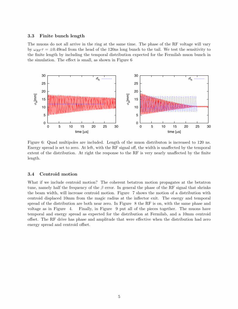
3.3 Finite bunch length
The muons do not all arrive in the ring at the same time. The phase of the RF voltage will varyby ωRF τ = ±0.49rad from the head of the 120ns long bunch to the tail. We test the sensitivity tothe finite length by including the temporal distribution expected for the Fermilab muon bunch inthe simulation. The effect is small, as shown in Figure 6
0
5
10
15
20
25
30
0 5 10 15 20 25 30
σx[m
m]
time [µs]
rfh
0
5
10
15
20
25
30
0 5 10 15 20 25 30σ
x[mm
]time [µs]
rfh
Figure 6: Quad multipoles are included. Length of the muon distributon is increased to 120 ns.Energy spread is set to zero. At left, with the RF signal off, the width is unaffected by the temporalextent of the distribution. At right the response to the RF is very nearly unaffected by the finitelength.
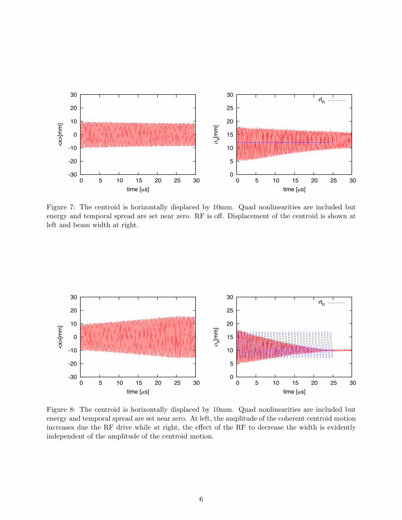
3.4 Centroid motion
What if we include centroid motion? The coherent betatron motion propagates at the betatrontune, namely half the frequency of the β error. In general the phase of the RF signal that shrinksthe beam width, will increase centroid motion. Figure 7 shows the motion of a distribution withcentroid displaced 10mm from the magic radius at the inflector exit. The energy and temporalspread of the distribution are both near zero. In Figure 8 the RF is on, with the same phase andvoltage as in Figure 4. Finally, in Figure 9 put all of the pieces together. The muons havetemporal and energy spread as expected for the distribution at Fermilab, and a 10mm centroidoffset. The RF drive has phase and amplitude that were effective when the distribution had zeroenergy spread and centroid offset.
5
-30
-20
-10
0
10
20
30
0 5 10 15 20 25 30
<x>[
mm
]
time [µs]
0
5
10
15
20
25
30
0 5 10 15 20 25 30
σx[m
m]
time [µs]
rfh
Figure 7: The centroid is horizontally displaced by 10mm. Quad nonlinearities are included butenergy and temporal spread are set near zero. RF is off. Displacement of the centroid is shown atleft and beam width at right.
-30
-20
-10
0
10
20
30
0 5 10 15 20 25 30
<x>[
mm
]
time [µs]
0
5
10
15
20
25
30
0 5 10 15 20 25 30
σx[m
m]
time [µs]
rfh
Figure 8: The centroid is horizontally displaced by 10mm. Quad nonlinearities are included butenergy and temporal spread are set near zero. At left, the amplitude of the coherent centroid motionincreases due the RF drive while at right, the effect of the RF to decrease the width is evidentlyindependent of the amplitude of the centroid motion.
6
-30
-20
-10
0
10
20
30
0 5 10 15 20 25 30
<x>[
mm
]
time [µs]
0
5
10
15
20
25
30
0 5 10 15 20 25 30
σx[m
m]
time [µs]
rfh
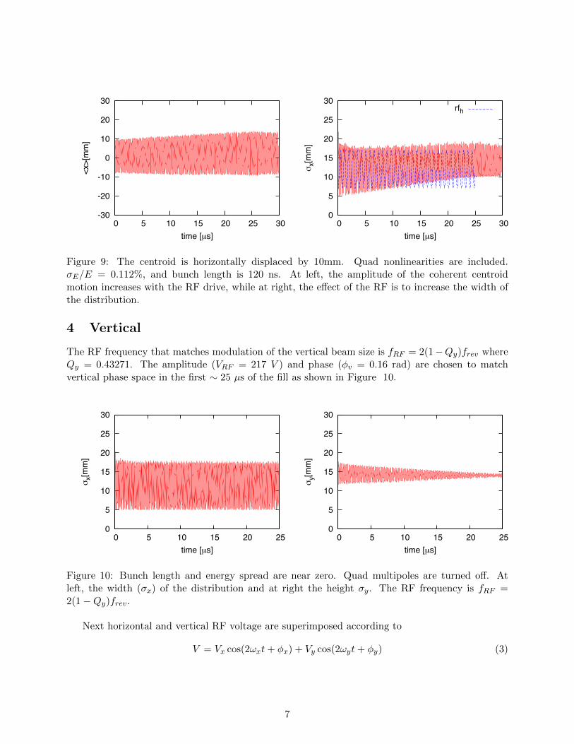
Figure 9: The centroid is horizontally displaced by 10mm. Quad nonlinearities are included.σE/E = 0.112%, and bunch length is 120 ns. At left, the amplitude of the coherent centroidmotion increases with the RF drive, while at right, the effect of the RF is to increase the width ofthe distribution.
4 Vertical
The RF frequency that matches modulation of the vertical beam size is fRF = 2(1−Qy)frev whereQy = 0.43271. The amplitude (VRF = 217 V ) and phase (φv = 0.16 rad) are chosen to matchvertical phase space in the first ∼ 25 µs of the fill as shown in Figure 10.
0
5
10
15
20
25
30
0 5 10 15 20 25
σx[m
m]
time [µs]
0
5
10
15
20
25
30
0 5 10 15 20 25
σy[m
m]
time [µs]
Figure 10: Bunch length and energy spread are near zero. Quad multipoles are turned off. Atleft, the width (σx) of the distribution and at right the height σy. The RF frequency is fRF =2(1 −Qy)frev.
Next horizontal and vertical RF voltage are superimposed according to
V = Vx cos(2ωxt+ φx) + Vy cos(2ωyt+ φy) (3)
7
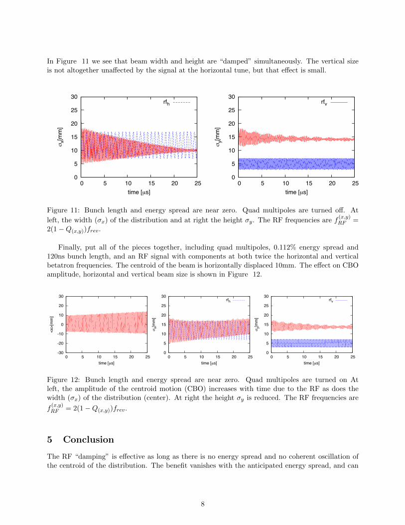
In Figure 11 we see that beam width and height are “damped” simultaneously. The vertical sizeis not altogether unaffected by the signal at the horizontal tune, but that effect is small.
0
5
10
15
20
25
30
0 5 10 15 20 25
σx[m
m]
time [µs]
rfh
0
5
10
15
20
25
30
0 5 10 15 20 25
σy[m
m]
time [µs]
rfv
Figure 11: Bunch length and energy spread are near zero. Quad multipoles are turned off. At
left, the width (σx) of the distribution and at right the height σy. The RF frequencies are f(x,y)RF =
2(1 −Q(x,y))frev.
Finally, put all of the pieces together, including quad multipoles, 0.112% energy spread and120ns bunch length, and an RF signal with components at both twice the horizontal and verticalbetatron frequencies. The centroid of the beam is horizontally displaced 10mm. The effect on CBOamplitude, horizontal and vertical beam size is shown in Figure 12.
-30
-20
-10
0
10
20
30
0 5 10 15 20 25
<x>[
mm
]
time [µs]
0
5
10
15
20
25
30
0 5 10 15 20 25
σx[m
m]
time [µs]
rfh
0
5
10
15
20
25
30
0 5 10 15 20 25
σy[m
m]
time [µs]
rfv
Figure 12: Bunch length and energy spread are near zero. Quad multipoles are turned on Atleft, the amplitude of the centroid motion (CBO) increases with time due to the RF as does thewidth (σx) of the distribution (center). At right the height σy is reduced. The RF frequencies are
f(x,y)RF = 2(1 −Q(x,y))frev.
5 Conclusion
The RF “damping” is effective as long as there is no energy spread and no coherent oscillation ofthe centroid of the distribution. The benefit vanishes with the anticipated energy spread, and can
8

increase the amplitude of centroid motion.
9


![RF circuits design 6ue.pwr.wroc.pl/.../lecture/RF_circuits_design_6.pdfAmplifier block diagram RF transistor [S] Output matching circuit Input matching circuit BIAS circuit ZG ZL Amplifier](https://img.pdfslide.us/doc/110x75/5e41026cfd4507719c31d8c5/rf-circuits-design-6uepwrwrocpllecturerfcircuitsdesign6pdf-amplifier.jpg)


![RF Circuit Design - [Ch2-1] Resonator and Impedance Matching](https://img.pdfslide.us/doc/110x75/55cf0400bb61ebc1078b47c8/rf-circuit-design-ch2-1-resonator-and-impedance-matching.jpg)