Embed Size (px)
Citation preview
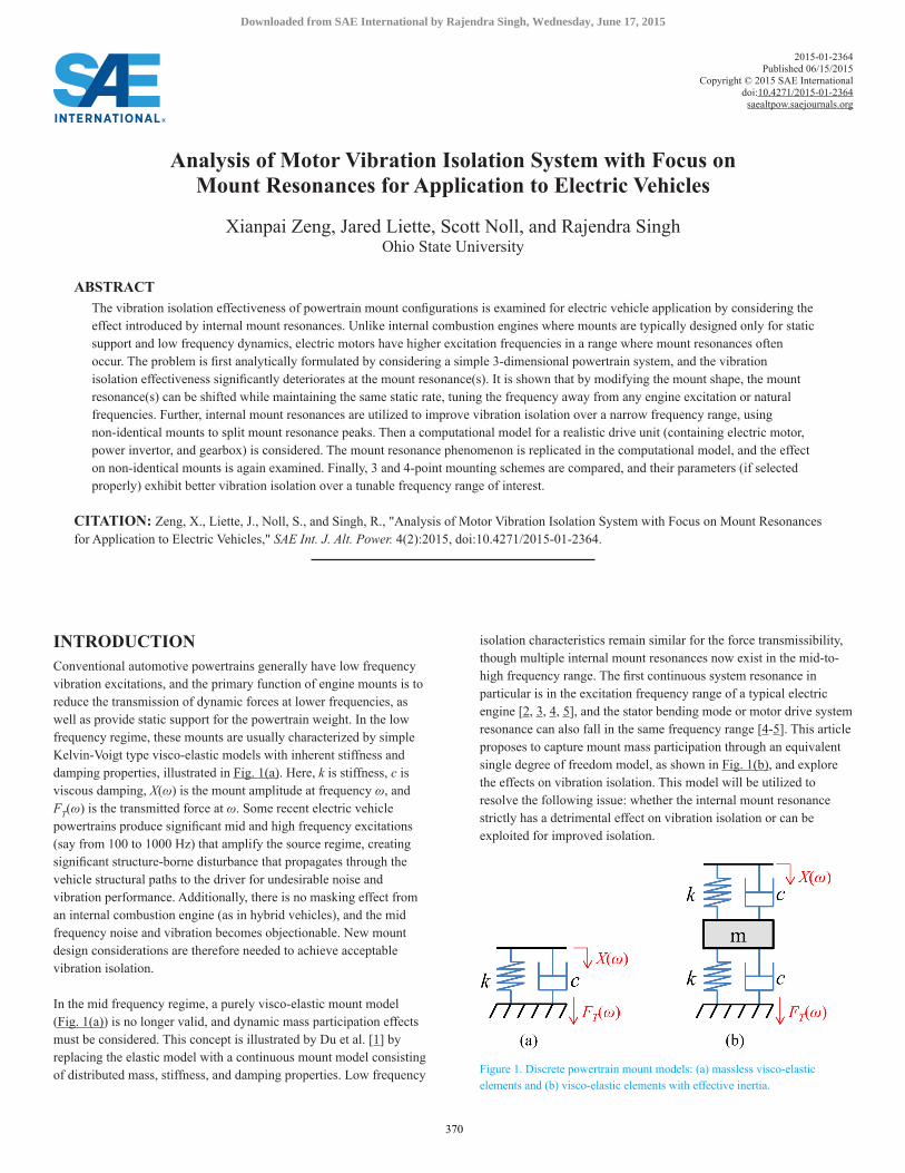
INTRODUCTIONConventional automotive powertrains generally have low frequency vibration excitations, and the primary function of engine mounts is to reduce the transmission of dynamic forces at lower frequencies, as well as provide static support for the powertrain weight. In the low frequency regime, these mounts are usually characterized by simple Kelvin-Voigt type visco-elastic models with inherent stiffness and damping properties, illustrated in Fig. 1(a). Here, k is stiffness, c is viscous damping, X(ω) is the mount amplitude at frequency ω, and FT(ω) is the transmitted force at ω. Some recent electric vehicle powertrains produce significant mid and high frequency excitations (say from 100 to 1000 Hz) that amplify the source regime, creating significant structure-borne disturbance that propagates through the vehicle structural paths to the driver for undesirable noise and vibration performance. Additionally, there is no masking effect from an internal combustion engine (as in hybrid vehicles), and the mid frequency noise and vibration becomes objectionable. New mount design considerations are therefore needed to achieve acceptable vibration isolation.
In the mid frequency regime, a purely visco-elastic mount model (Fig. 1(a)) is no longer valid, and dynamic mass participation effects must be considered. This concept is illustrated by Du et al. [1] by replacing the elastic model with a continuous mount model consisting of distributed mass, stiffness, and damping properties. Low frequency
isolation characteristics remain similar for the force transmissibility, though multiple internal mount resonances now exist in the mid-to-high frequency range. The first continuous system resonance in particular is in the excitation frequency range of a typical electric engine [2, 3, 4, 5], and the stator bending mode or motor drive system resonance can also fall in the same frequency range [4-5]. This article proposes to capture mount mass participation through an equivalent single degree of freedom model, as shown in Fig. 1(b), and explore the effects on vibration isolation. This model will be utilized to resolve the following issue: whether the internal mount resonance strictly has a detrimental effect on vibration isolation or can be exploited for improved isolation.
Figure 1. Discrete powertrain mount models: (a) massless visco-elastic elements and (b) visco-elastic elements with effective inertia.
Analysis of Motor Vibration Isolation System with Focus on Mount Resonances for Application to Electric Vehicles
Xianpai Zeng, Jared Liette, Scott Noll, and Rajendra SinghOhio State University
ABSTRACTThe vibration isolation effectiveness of powertrain mount configurations is examined for electric vehicle application by considering the effect introduced by internal mount resonances. Unlike internal combustion engines where mounts are typically designed only for static support and low frequency dynamics, electric motors have higher excitation frequencies in a range where mount resonances often occur. The problem is first analytically formulated by considering a simple 3-dimensional powertrain system, and the vibration isolation effectiveness significantly deteriorates at the mount resonance(s). It is shown that by modifying the mount shape, the mount resonance(s) can be shifted while maintaining the same static rate, tuning the frequency away from any engine excitation or natural frequencies. Further, internal mount resonances are utilized to improve vibration isolation over a narrow frequency range, using non-identical mounts to split mount resonance peaks. Then a computational model for a realistic drive unit (containing electric motor, power invertor, and gearbox) is considered. The mount resonance phenomenon is replicated in the computational model, and the effect on non-identical mounts is again examined. Finally, 3 and 4-point mounting schemes are compared, and their parameters (if selected properly) exhibit better vibration isolation over a tunable frequency range of interest.
CITATION: Zeng, X., Liette, J., Noll, S., and Singh, R., "Analysis of Motor Vibration Isolation System with Focus on Mount Resonances for Application to Electric Vehicles," SAE Int. J. Alt. Power. 4(2):2015, doi:10.4271/2015-01-2364.
2015-01-2364Published 06/15/2015
Copyright © 2015 SAE Internationaldoi:10.4271/2015-01-2364
saealtpow.saejournals.org
370
Downloaded from SAE International by Rajendra Singh, Wednesday, June 17, 2015
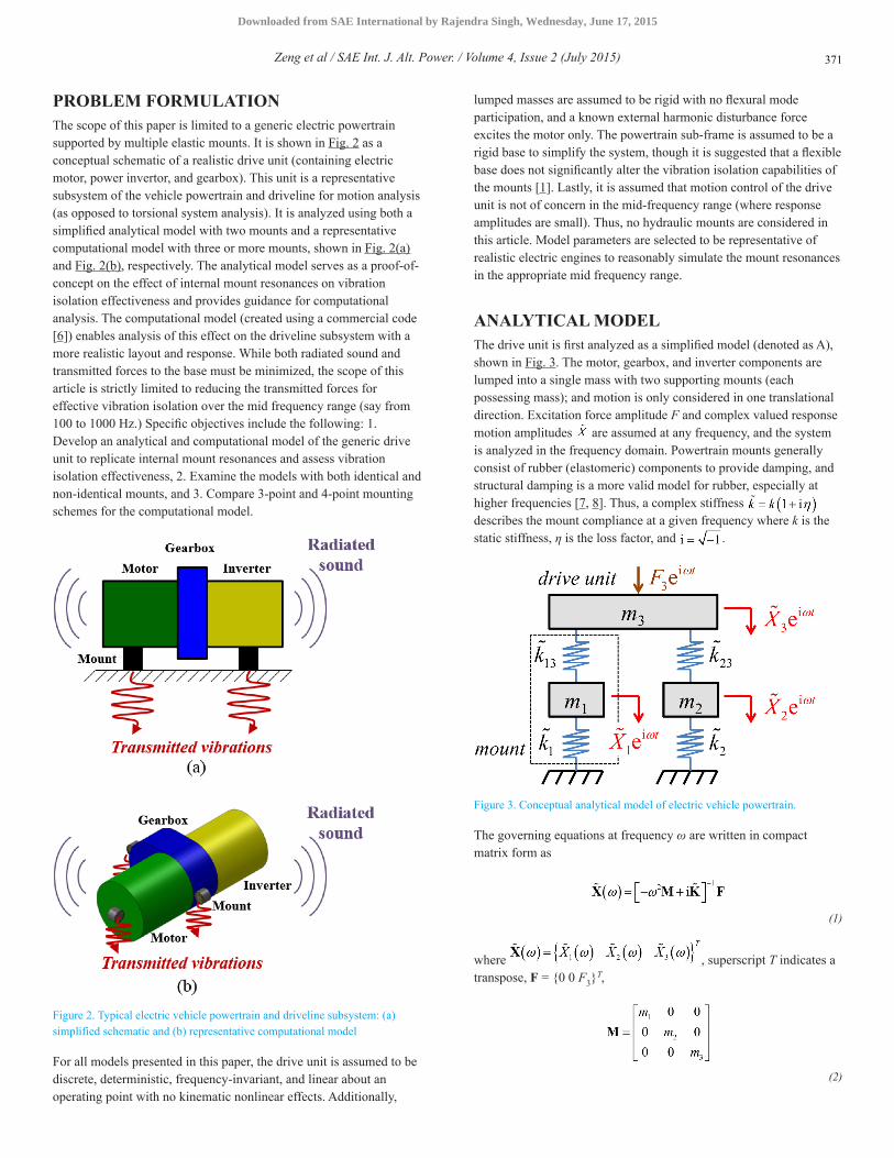
PROBLEM FORMULATIONThe scope of this paper is limited to a generic electric powertrain supported by multiple elastic mounts. It is shown in Fig. 2 as a conceptual schematic of a realistic drive unit (containing electric motor, power invertor, and gearbox). This unit is a representative subsystem of the vehicle powertrain and driveline for motion analysis (as opposed to torsional system analysis). It is analyzed using both a simplified analytical model with two mounts and a representative computational model with three or more mounts, shown in Fig. 2(a) and Fig. 2(b), respectively. The analytical model serves as a proof-of-concept on the effect of internal mount resonances on vibration isolation effectiveness and provides guidance for computational analysis. The computational model (created using a commercial code [6]) enables analysis of this effect on the driveline subsystem with a more realistic layout and response. While both radiated sound and transmitted forces to the base must be minimized, the scope of this article is strictly limited to reducing the transmitted forces for effective vibration isolation over the mid frequency range (say from 100 to 1000 Hz.) Specific objectives include the following: 1. Develop an analytical and computational model of the generic drive unit to replicate internal mount resonances and assess vibration isolation effectiveness, 2. Examine the models with both identical and non-identical mounts, and 3. Compare 3-point and 4-point mounting schemes for the computational model.
Figure 2. Typical electric vehicle powertrain and driveline subsystem: (a) simplified schematic and (b) representative computational model
For all models presented in this paper, the drive unit is assumed to be discrete, deterministic, frequency-invariant, and linear about an operating point with no kinematic nonlinear effects. Additionally,
lumped masses are assumed to be rigid with no flexural mode participation, and a known external harmonic disturbance force excites the motor only. The powertrain sub-frame is assumed to be a rigid base to simplify the system, though it is suggested that a flexible base does not significantly alter the vibration isolation capabilities of the mounts [1]. Lastly, it is assumed that motion control of the drive unit is not of concern in the mid-frequency range (where response amplitudes are small). Thus, no hydraulic mounts are considered in this article. Model parameters are selected to be representative of realistic electric engines to reasonably simulate the mount resonances in the appropriate mid frequency range.
ANALYTICAL MODELThe drive unit is first analyzed as a simplified model (denoted as A), shown in Fig. 3. The motor, gearbox, and inverter components are lumped into a single mass with two supporting mounts (each possessing mass); and motion is only considered in one translational direction. Excitation force amplitude F and complex valued response motion amplitudes are assumed at any frequency, and the system is analyzed in the frequency domain. Powertrain mounts generally consist of rubber (elastomeric) components to provide damping, and structural damping is a more valid model for rubber, especially at higher frequencies [7, 8]. Thus, a complex stiffness describes the mount compliance at a given frequency where k is the static stiffness, η is the loss factor, and .
Figure 3. Conceptual analytical model of electric vehicle powertrain.
The governing equations at frequency ω are written in compact matrix form as
(1)
where , superscript T indicates a transpose, F = {0 0 F3}
T,
(2)
Zeng et al / SAE Int. J. Alt. Power. / Volume 4, Issue 2 (July 2015) 371
Downloaded from SAE International by Rajendra Singh, Wednesday, June 17, 2015
is the inertia matrix, and
(3)
is the complex valued stiffness matrix. For a given excitation frequency,
(4)
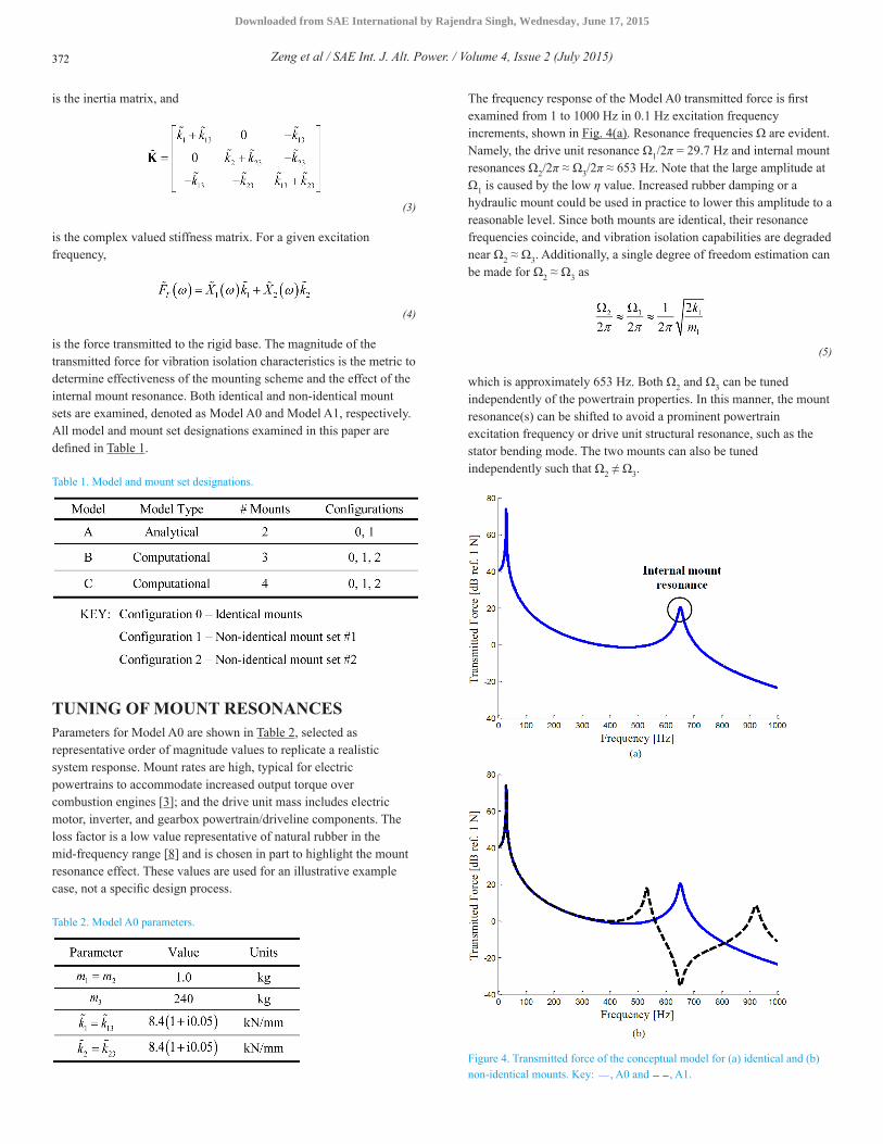
is the force transmitted to the rigid base. The magnitude of the transmitted force for vibration isolation characteristics is the metric to determine effectiveness of the mounting scheme and the effect of the internal mount resonance. Both identical and non-identical mount sets are examined, denoted as Model A0 and Model A1, respectively. All model and mount set designations examined in this paper are defined in Table 1.
Table 1. Model and mount set designations.
TUNING OF MOUNT RESONANCESParameters for Model A0 are shown in Table 2, selected as representative order of magnitude values to replicate a realistic system response. Mount rates are high, typical for electric powertrains to accommodate increased output torque over combustion engines [3]; and the drive unit mass includes electric motor, inverter, and gearbox powertrain/driveline components. The loss factor is a low value representative of natural rubber in the mid-frequency range [8] and is chosen in part to highlight the mount resonance effect. These values are used for an illustrative example case, not a specific design process.
Table 2. Model A0 parameters.
The frequency response of the Model A0 transmitted force is first examined from 1 to 1000 Hz in 0.1 Hz excitation frequency increments, shown in Fig. 4(a). Resonance frequencies Ω are evident. Namely, the drive unit resonance Ω1/2π = 29.7 Hz and internal mount resonances Ω2/2π ≈ Ω3/2π ≈ 653 Hz. Note that the large amplitude at Ω1 is caused by the low η value. Increased rubber damping or a hydraulic mount could be used in practice to lower this amplitude to a reasonable level. Since both mounts are identical, their resonance frequencies coincide, and vibration isolation capabilities are degraded near Ω2 ≈ Ω3. Additionally, a single degree of freedom estimation can be made for Ω2 ≈ Ω3 as
(5)
which is approximately 653 Hz. Both Ω2 and Ω3 can be tuned independently of the powertrain properties. In this manner, the mount resonance(s) can be shifted to avoid a prominent powertrain excitation frequency or drive unit structural resonance, such as the stator bending mode. The two mounts can also be tuned independently such that Ω2 ≠ Ω3.
Figure 4. Transmitted force of the conceptual model for (a) identical and (b) non-identical mounts. Key: , A0 and , A1.
Zeng et al / SAE Int. J. Alt. Power. / Volume 4, Issue 2 (July 2015)372
Downloaded from SAE International by Rajendra Singh, Wednesday, June 17, 2015
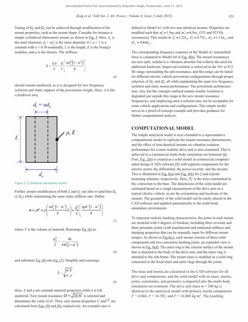
Tuning of Ω2 and Ω3 can be achieved through modification of the mount properties, such as the mount shape. Consider for instance a simple cylindrical elastomeric mount, as shown in Fig. 5. Here, do is the outer diameter, di = αdo is the inner diameter, 0 ≤ α < 1 is a constant with α = 0.50 nominally, L is the length, E is the Young's modulus, and ρ is the density. The stiffness
(6)
should remain unaltered, as it is designed for low frequency isolation and static support of the powertrain weight. Here, A is the cylindrical area.
Figure 5. Cylindrical elastomeric mount.
Further, proper modification of both L and do can alter m (and thus Ω2 or Ω3) while maintaining the same static stiffness rate. Define
(7)
where V is the volume of material. Rearrange Eq. (6) as
(8)
and substitute Eq. (8) into Eq. (7). Simplify and rearrange:
(9)
Here, E and ρ are constant material properties while k is left unaltered. New mount resonance is selected and determines the value of mʹ. Then, new mount properties Lʹ and are calculated from Eqs. (9) and (8), respectively. An example case is
defined as Model A1 with two non-identical mounts. Properties are modified such that and (533 and 923 Hz resonances). This results in , , , and
.
The corresponding frequency response of the Model A1 transmitted force is compared to Model A0 in Fig. 4(b). The mount resonances are now split, similar to a vibration absorber but without the need for additional hardware. Improved isolation is achieved in the 561 to 812 Hz range surrounding the anti-resonance, and this range can be tuned for different electric vehicle powertrain configurations through proper selection of and , all while maintaining the same low frequency isolation and static mount performance. The powertrain architecture may vary, but the concepts outlined remain similar. Isolation is degraded just outside this range at the new mount resonance frequencies, and employing such a solution may not be acceptable for some vehicle applications and configurations. This simple model serves as a proof-of-concept example and provides guidance for further computational analysis.
COMPUTATIONAL MODELThe simple analytical model is next extended to a representative computational model to replicate the mount resonance phenomenon, and the effect of non-identical mounts on vibration isolation performance for a more realistic drive unit is also examined. This is achieved in a commercial multi-body simulation environment [6]. First, Fig. 2(b) is created as a solid model in commercial computer-aided design (CAD) software [9] with separate components for the electric motor, the differential, the power inverter, and the mounts. This is illustrated in Fig. 6(a) and Fig. 6(b) for 3 and 4-point mounting schemes, respectively. Here, is the force transmitted in the z-direction to the base. The dimensions of the solid model are estimated based on a rough measurement of the drive unit on a typical electric vehicle, as are the orientations and locations of the mounts. The geometry of the solid model can be easily altered in the CAD software and updated automatically to the multi-body simulation environment.
To represent realistic bushing characteristics, the joints in each mount are modeled with 6 degrees of freedom, including three revolute and three prismatic joints (with translational and rotational stiffness and damping properties that can be manually input for different mount setups). As shown in Fig.6(c), each mount consists of three solid components and two concentric bushing joints; an exploded view is shown in Fig. 6(d). The outer ring is the exterior surface of the mount that is attached to the body of the drive unit, and the inner ring is attached to the sub-frame. The mount mass is modeled as a solid ring connected to the fixed inner and outer rings through the joints.
The mass and inertia are calculated in the CAD software for all drive unit components; and the solid model with its mass, inertia, joints, constraints, and geometry is imported into the multi-body simulation environment. The drive unit mass m = 240 kg is identical to the analytical model with primary inertia components Ix = 4.044, Iy = 16.702, and Iz = 16.068 kg-m2. The resulting
Zeng et al / SAE Int. J. Alt. Power. / Volume 4, Issue 2 (July 2015) 373
Downloaded from SAE International by Rajendra Singh, Wednesday, June 17, 2015
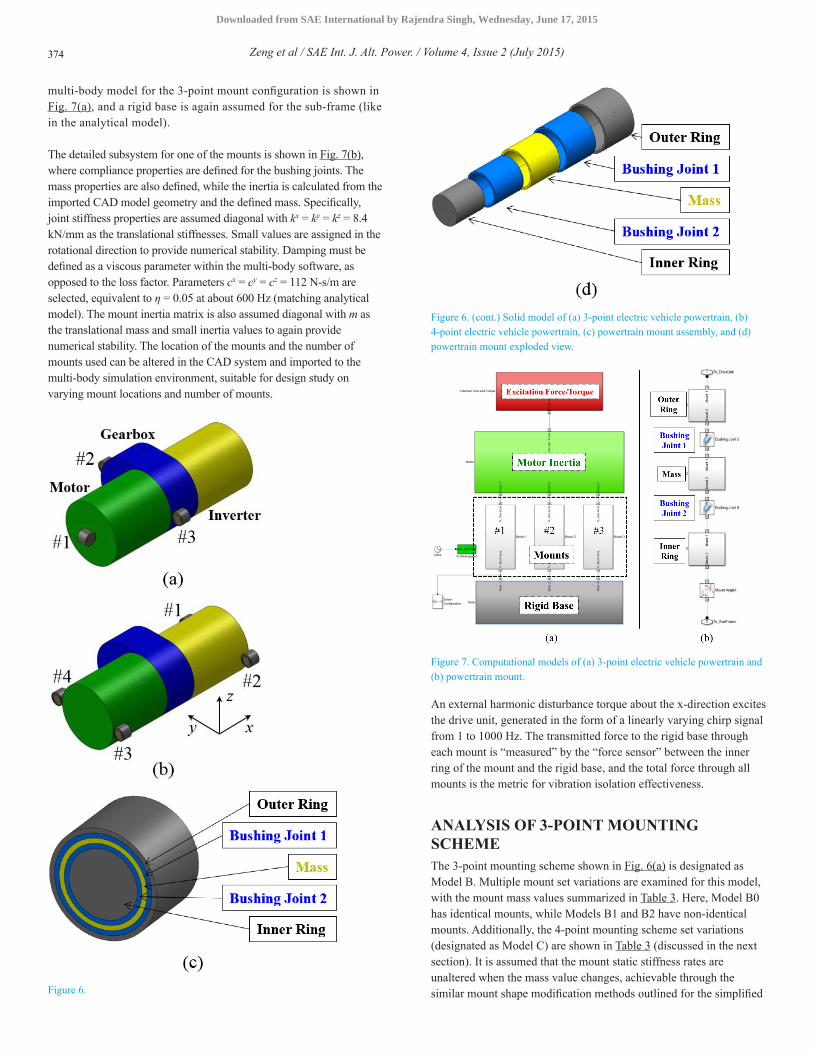
multi-body model for the 3-point mount configuration is shown in Fig. 7(a), and a rigid base is again assumed for the sub-frame (like in the analytical model).
The detailed subsystem for one of the mounts is shown in Fig. 7(b), where compliance properties are defined for the bushing joints. The mass properties are also defined, while the inertia is calculated from the imported CAD model geometry and the defined mass. Specifically, joint stiffness properties are assumed diagonal with kx = ky = kz = 8.4 kN/mm as the translational stiffnesses. Small values are assigned in the rotational direction to provide numerical stability. Damping must be defined as a viscous parameter within the multi-body software, as opposed to the loss factor. Parameters cx = cy = cz = 112 N-s/m are selected, equivalent to η = 0.05 at about 600 Hz (matching analytical model). The mount inertia matrix is also assumed diagonal with m as the translational mass and small inertia values to again provide numerical stability. The location of the mounts and the number of mounts used can be altered in the CAD system and imported to the multi-body simulation environment, suitable for design study on varying mount locations and number of mounts.
Figure 6.
Figure 6. (cont.) Solid model of (a) 3-point electric vehicle powertrain, (b) 4-point electric vehicle powertrain, (c) powertrain mount assembly, and (d) powertrain mount exploded view.
Figure 7. Computational models of (a) 3-point electric vehicle powertrain and (b) powertrain mount.
An external harmonic disturbance torque about the x-direction excites the drive unit, generated in the form of a linearly varying chirp signal from 1 to 1000 Hz. The transmitted force to the rigid base through each mount is “measured” by the “force sensor” between the inner ring of the mount and the rigid base, and the total force through all mounts is the metric for vibration isolation effectiveness.
ANALYSIS OF 3-POINT MOUNTING SCHEMEThe 3-point mounting scheme shown in Fig. 6(a) is designated as Model B. Multiple mount set variations are examined for this model, with the mount mass values summarized in Table 3. Here, Model B0 has identical mounts, while Models B1 and B2 have non-identical mounts. Additionally, the 4-point mounting scheme set variations (designated as Model C) are shown in Table 3 (discussed in the next section). It is assumed that the mount static stiffness rates are unaltered when the mass value changes, achievable through the similar mount shape modification methods outlined for the simplified
Zeng et al / SAE Int. J. Alt. Power. / Volume 4, Issue 2 (July 2015)374
Downloaded from SAE International by Rajendra Singh, Wednesday, June 17, 2015
analytical model. The stiffness expression would change for the horizontally oriented mount. Detailed shape modification methods are not derived in this paper.
Table 3. Mount set parameters for Model B and Model C.
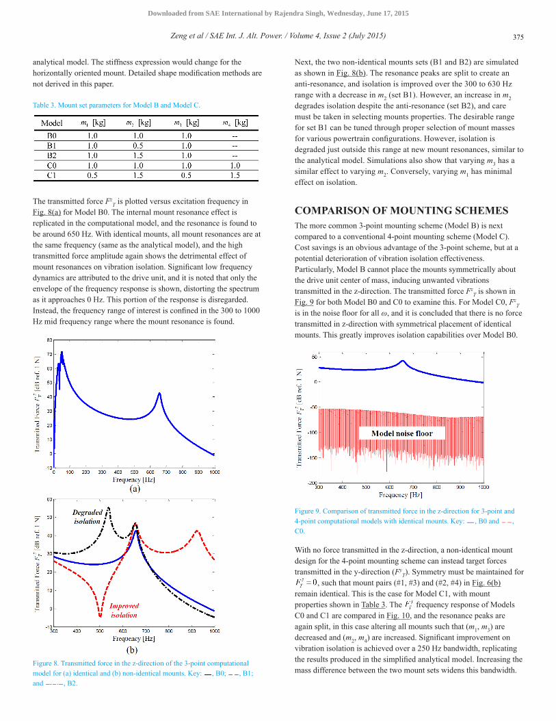
The transmitted force FzT is plotted versus excitation frequency in
Fig. 8(a) for Model B0. The internal mount resonance effect is replicated in the computational model, and the resonance is found to be around 650 Hz. With identical mounts, all mount resonances are at the same frequency (same as the analytical model), and the high transmitted force amplitude again shows the detrimental effect of mount resonances on vibration isolation. Significant low frequency dynamics are attributed to the drive unit, and it is noted that only the envelope of the frequency response is shown, distorting the spectrum as it approaches 0 Hz. This portion of the response is disregarded. Instead, the frequency range of interest is confined in the 300 to 1000 Hz mid frequency range where the mount resonance is found.
Figure 8. Transmitted force in the z-direction of the 3-point computational model for (a) identical and (b) non-identical mounts. Key: , B0; , B1; and , B2.
Next, the two non-identical mounts sets (B1 and B2) are simulated as shown in Fig. 8(b). The resonance peaks are split to create an anti-resonance, and isolation is improved over the 300 to 630 Hz range with a decrease in m2 (set B1). However, an increase in m2 degrades isolation despite the anti-resonance (set B2), and care must be taken in selecting mounts properties. The desirable range for set B1 can be tuned through proper selection of mount masses for various powertrain configurations. However, isolation is degraded just outside this range at new mount resonances, similar to the analytical model. Simulations also show that varying m3 has a similar effect to varying m2. Conversely, varying m1 has minimal effect on isolation.
COMPARISON OF MOUNTING SCHEMESThe more common 3-point mounting scheme (Model B) is next compared to a conventional 4-point mounting scheme (Model C). Cost savings is an obvious advantage of the 3-point scheme, but at a potential deterioration of vibration isolation effectiveness. Particularly, Model B cannot place the mounts symmetrically about the drive unit center of mass, inducing unwanted vibrations transmitted in the z-direction. The transmitted force Fz
T is shown in Fig. 9 for both Model B0 and C0 to examine this. For Model C0, Fz
T is in the noise floor for all ω, and it is concluded that there is no force transmitted in z-direction with symmetrical placement of identical mounts. This greatly improves isolation capabilities over Model B0.
Figure 9. Comparison of transmitted force in the z-direction for 3-point and 4-point computational models with identical mounts. Key: , B0 and , C0.
With no force transmitted in the z-direction, a non-identical mount design for the 4-point mounting scheme can instead target forces transmitted in the y-direction (Fy
T). Symmetry must be maintained for , such that mount pairs (#1, #3) and (#2, #4) in Fig. 6(b)
remain identical. This is the case for Model C1, with mount properties shown in Table 3. The frequency response of Models C0 and C1 are compared in Fig. 10, and the resonance peaks are again split, in this case altering all mounts such that (m1, m3) are decreased and (m2, m4) are increased. Significant improvement on vibration isolation is achieved over a 250 Hz bandwidth, replicating the results produced in the simplified analytical model. Increasing the mass difference between the two mount sets widens this bandwidth.
Zeng et al / SAE Int. J. Alt. Power. / Volume 4, Issue 2 (July 2015) 375
Downloaded from SAE International by Rajendra Singh, Wednesday, June 17, 2015
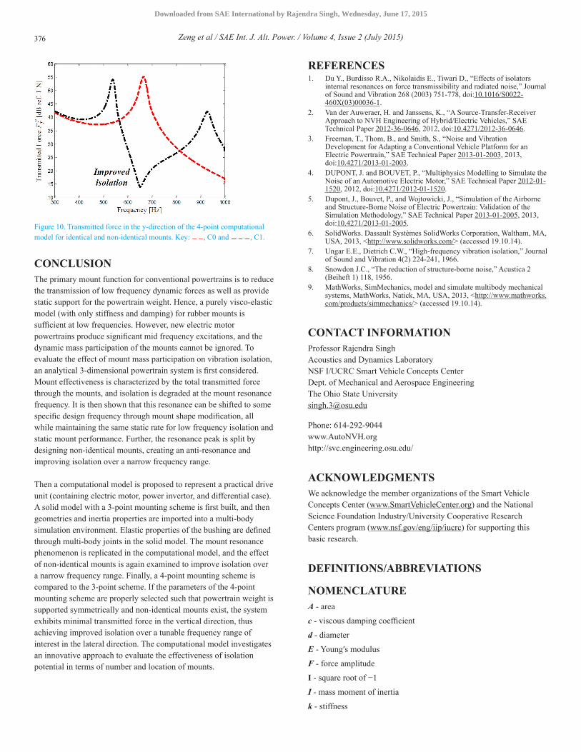
Figure 10. Transmitted force in the y-direction of the 4-point computational model for identical and non-identical mounts. Key: , C0 and , C1.
CONCLUSIONThe primary mount function for conventional powertrains is to reduce the transmission of low frequency dynamic forces as well as provide static support for the powertrain weight. Hence, a purely visco-elastic model (with only stiffness and damping) for rubber mounts is sufficient at low frequencies. However, new electric motor powertrains produce significant mid frequency excitations, and the dynamic mass participation of the mounts cannot be ignored. To evaluate the effect of mount mass participation on vibration isolation, an analytical 3-dimensional powertrain system is first considered. Mount effectiveness is characterized by the total transmitted force through the mounts, and isolation is degraded at the mount resonance frequency. It is then shown that this resonance can be shifted to some specific design frequency through mount shape modification, all while maintaining the same static rate for low frequency isolation and static mount performance. Further, the resonance peak is split by designing non-identical mounts, creating an anti-resonance and improving isolation over a narrow frequency range.
Then a computational model is proposed to represent a practical drive unit (containing electric motor, power invertor, and differential case). A solid model with a 3-point mounting scheme is first built, and then geometries and inertia properties are imported into a multi-body simulation environment. Elastic properties of the bushing are defined through multi-body joints in the solid model. The mount resonance phenomenon is replicated in the computational model, and the effect of non-identical mounts is again examined to improve isolation over a narrow frequency range. Finally, a 4-point mounting scheme is compared to the 3-point scheme. If the parameters of the 4-point mounting scheme are properly selected such that powertrain weight is supported symmetrically and non-identical mounts exist, the system exhibits minimal transmitted force in the vertical direction, thus achieving improved isolation over a tunable frequency range of interest in the lateral direction. The computational model investigates an innovative approach to evaluate the effectiveness of isolation potential in terms of number and location of mounts.
REFERENCES1. Du Y., Burdisso R.A., Nikolaidis E., Tiwari D., “Effects of isolators
internal resonances on force transmissibility and radiated noise,” Journal of Sound and Vibration 268 (2003) 751-778, doi:10.1016/S0022-460X(03)00036-1.
2. Van der Auweraer, H. and Janssens, K., “A Source-Transfer-Receiver Approach to NVH Engineering of Hybrid/Electric Vehicles,” SAE Technical Paper 2012-36-0646, 2012, doi:10.4271/2012-36-0646.
3. Freeman, T., Thom, B., and Smith, S., “Noise and Vibration Development for Adapting a Conventional Vehicle Platform for an Electric Powertrain,” SAE Technical Paper 2013-01-2003, 2013, doi:10.4271/2013-01-2003.
4. DUPONT, J. and BOUVET, P., “Multiphysics Modelling to Simulate the Noise of an Automotive Electric Motor,” SAE Technical Paper 2012-01-1520, 2012, doi:10.4271/2012-01-1520.
5. Dupont, J., Bouvet, P., and Wojtowicki, J., “Simulation of the Airborne and Structure-Borne Noise of Electric Powertrain: Validation of the Simulation Methodology,” SAE Technical Paper 2013-01-2005, 2013, doi:10.4271/2013-01-2005.
6. SolidWorks. Dassault Systèmes SolidWorks Corporation, Waltham, MA, USA, 2013, <http://www.solidworks.com/> (accessed 19.10.14).
7. Ungar E.E., Dietrich C.W., “High-frequency vibration isolation,” Journal of Sound and Vibration 4(2) 224-241, 1966.
8. Snowdon J.C., “The reduction of structure-borne noise,” Acustica 2 (Beiheft 1) 118, 1956.
9. MathWorks, SimMechanics, model and simulate multibody mechanical systems, MathWorks, Natick, MA, USA, 2013, <http://www.mathworks.com/products/simmechanics/> (accessed 19.10.14).
CONTACT INFORMATIONProfessor Rajendra SinghAcoustics and Dynamics LaboratoryNSF I/UCRC Smart Vehicle Concepts CenterDept. of Mechanical and Aerospace EngineeringThe Ohio State [email protected]
Phone: 614-292-9044www.AutoNVH.orghttp://svc.engineering.osu.edu/
ACKNOWLEDGMENTSWe acknowledge the member organizations of the Smart Vehicle Concepts Center (www.SmartVehicleCenter.org) and the National Science Foundation Industry/University Cooperative Research Centers program (www.nsf.gov/eng/iip/iucrc) for supporting this basic research.
DEFINITIONS/ABBREVIATIONS
NOMENCLATUREA - area
c - viscous damping coefficient
d - diameter
E - Youngʹs modulus
F - force amplitude
I - square root of −1
I - mass moment of inertia
k - stiffness
Zeng et al / SAE Int. J. Alt. Power. / Volume 4, Issue 2 (July 2015)376
Downloaded from SAE International by Rajendra Singh, Wednesday, June 17, 2015
- complex valued stiffness
- complex valued stiffness matrix
L - length
m - mass
M - inertia matrix
t - time
V - volume
x, y, z - Cartesian coordinates
X - displacement amplitude
α - constant
η - loss factor
ρ - density
ω - circular frequency (rad sec−1)
Ω - resonance frequency (rad sec−1)
SUBSCRIPTS1,2,3,… - general indices
i - inner
o - outer
T - transmitted
SUPERSCRIPTSx, y, z - referenced to Cartesian coordinates
ʹ - altered model A parameter
~ - complex valued
ABBREVIATIONSCAD - computer-aided design
All rights reserved. No part of this publication may be reproduced, stored in a retrieval system, or transmitted, in any form or by any means, electronic, mechanical, photocopying, recording, or otherwise, without the prior written permission of SAE International.
Positions and opinions advanced in this paper are those of the author(s) and not necessarily those of SAE International. The author is solely responsible for the content of the paper.
Zeng et al / SAE Int. J. Alt. Power. / Volume 4, Issue 2 (July 2015) 377
Downloaded from SAE International by Rajendra Singh, Wednesday, June 17, 2015