Embed Size (px)
Citation preview
Available online at www.sciencedirect.com
www.elsevier.com/locate/compstruc
Computers and Structures 86 (2008) 347–356
Analysis of morphing, multi stable structures actuatedby piezoelectric patches
Pedro Portela a,*, Pedro Camanho a, Paul Weaver b, Ian Bond b
a Faculdade de Engenharia da Universidade do Porto, Rua Roberto Frias s/n 4200-465 Porto, Portugalb Department of Aerospace Engineering, University of Bristol, Queen’s Building, University Walk, Bristol BS8 1TR, United Kingdom
Available online 11 April 2007
Abstract
In this article a novel morphing structure concept is studied using non-linear Finite Element Analysis (FEA). Bi-stable asymmetricallaminates can be snapped between two geometries through a buckling mechanism that is activated by an applied load. A piezoelectricMacro-Fibre Composite (MFC) actuator was chosen to provide this activation load. Bi-stable structures will maintain a given geomet-rical state without the need for a constant actuation force. FEA was used to predict the two stable geometries, to understand the bucklingmechanism and to evaluate the feasibility of using MFC actuators for switching between states. Environmental effects like moistureabsorption were also included in the analysis.� 2007 Elsevier Ltd. All rights reserved.
Keywords: Morphing structures; Asymmetrical laminates; Snap-through; MFC; Morphing; Multistable plates; Composites; Piezoelectric; Actuation;FE modelling
1. Introduction
The expression ‘‘Morphing Structures’’ is a very broadand much underdefined subject. In this text a morphingstructure will be defined as one capable of macroscopicgeometric changes in order to better adapt to radically dif-ferent environmental conditions. Because of the resourcesavailable in the aerospace industry and because of the clearadvantages that these technologies can bring, morphingstructures applications are currently under study, for exam-ple, for airplane wing geometry changes, replacement ofmechanically driven control surfaces, helicopter blade con-trol, and reliable actuators for space missions. If a morp-hing aircraft is defined merely as an aircraft that changesits configuration in-flight, it can be seen that a morphingaircraft is not a new concept. Extending flaps, elevators,ailerons and wing twisting can be considered geometricchanges and can be technically termed as morphing.
0045-7949/$ - see front matter � 2007 Elsevier Ltd. All rights reserved.
doi:10.1016/j.compstruc.2007.01.032
* Corresponding author.E-mail address: [email protected] (P. Portela).
However, these changes are either necessary enablers forcontrolled flight or contributors to the improved aerody-namic performances of an aircraft. As a result, these tech-nologies do not necessarily allow an aircraft to performdifferent types of mission tasks [1]. Recently Schultz et al.[2] proposed a novel morphing concept based on asymmet-rical carbon fibre reinforced plastic (CFRP) laminates. If acomposite laminate does not have a symmetrical stackingsequence, thermally induced stresses develop during thecuring process and cause an out of plane curvature. Thiscurvature can be tailored by adjusting the stackingsequence and ply thickness. Depending on the plate geom-etry the thermally induced stresses may cause the laminateto have more than one stable configuration or shape.Morphing can be obtained by alternating between thesestates. The main advantage of using these structures is thatthey will hold one of the stable shapes without the need of aforce holding them in that position. Hence, they can carryloads in both states as long as they do not reach the criticalsnap-through load. Schultz [2,3] used piezoelectric patchesbonded to the surface of the laminate to induce snap-through with a shear force. This type of device uses both
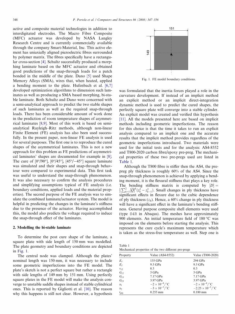
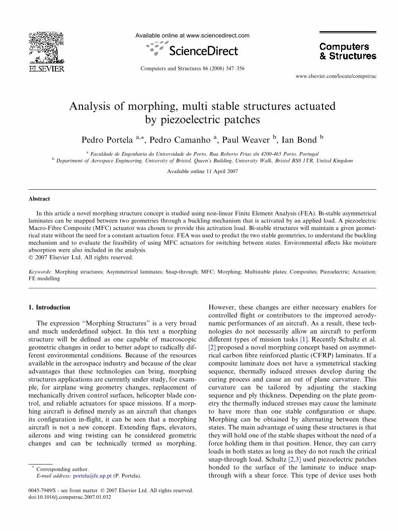
Fig. 1. FE model boundary conditions.
Table 1Mechanical properties of the two different pre-pregs
Property Value (AS4-8552) Value (T800-2020)
E1 135 GPa 294 GPaE2 9.5 GPa 9.5 GPam12 0.3 0.3G12 5 GPa 5 GPaG13 7.17 GPa 7.17 GPaG23 3.97 GPa 3.97 GPaa1 �2� 10�8=�C �2� 10�8=�Ca2 �3� 10�5=�C �2:25� 10�5=�Ctply 0.255 mm 0.180 mm
348 P. Portela et al. / Computers and Structures 86 (2008) 347–356
active and composite material technologies in addition tointerdigitated electrodes. The Macro Fibre Composite(MFC) actuator was developed by NASA LangleyResearch Centre and is currently commercially availablethrough the company Smart-Material, Inc. This active ele-ment has uniaxially aligned piezoelectric fibres surroundedby polymer matrix. The fibres specifically have a rectangu-lar cross-section [4]. Schultz successfully produced a morp-hing laminate based on the MFC actuator and obtainedgood predictions of the snap-through loads for a patchbonded in the middle of the plate. Dano [5] used ShapeMemory Alloys (SMA), wires that, when heated, applieda bending moment to the plate. Hufenbach et al. [6,7]developed optimization algorithms to dimension such lam-inates as well as producing a SMA based morphing, bi-sta-ble laminate. Both Schultz and Dano were concerned witha semi-analytical approach to predict the two stable shapesof such laminates as well as the required snap-throughloads. There has been considerable amount of work donein the prediction of room temperature shapes of asymmet-rical laminates [8,9]. Most of this work is based on semi-analytical Rayleigh–Ritz methods, although non-linearFinite Element (FE) analysis has also been used success-fully. In the present paper, non-linear FE analysis is usedfor several purposes. The first one is to reproduce the curedshapes of the asymmetrical laminates. This is not a newapproach for this problem as FE predictions of asymmetri-cal laminates’ shapes are documented for example in [8].The cure of [0�/90�], [0�/45�], [45�/�45�] square laminatewas simulated and their shapes and snap-through behav-iour were compared to experimental data. This first taskwas useful to understand the snap-through phenomenon.It was also necessary to confirm the analysis proceduresand simplifying assumptions typical of FE analysis (i.e.boundary conditions, applied loads and the material prop-erties). The second purpose of the FE analysis was to sim-ulate the combined laminate/actuator system. The model ishelpful in predicting the changes in the laminate’s stiffnessdue to the presence of the actuator. Having accomplishedthis, the model also predicts the voltage required to inducethe snap-through effect of the laminates.
2. Modelling the bi-stable laminate
To determine the post cure shape of the laminate, asquare plate with side length of 150 mm was modelled.The plate geometry and boundary conditions are depictedin Fig. 1.
The central node was clamped. Although the plates’nominal length was 150 mm, it was necessary to includesome geometric imperfections into the FE model. Theplate’s sketch is not a perfect square but rather a rectanglewith side lengths of 149 mm by 151 mm. Using perfectlysquare plates in the FE model will make the analysis con-verge to unstable saddle shapes instead of stable cylindricalones. This is reported by Gigliotti et al. [10]. The reasonwhy this happens is still not clear. However, a hypothesis
was formulated that the inertia forces played a role in thecurvature development. If instead of an implicit methodan explicit method or an implicit direct-integrationdynamic method is used to predict the cured shapes, theperfectly square plate will converge into a stable cylinder.An explicit model was created and verified this hypothesis[11]. All the models presented here are based on implicitmethods including geometric imperfections. The reasonfor this choice is that the time it takes to run an explicitanalysis compared to an implicit one and the accurateresults that the implicit method provides regardless of thegeometric imperfections introduced. Two materials wereused for the initial tests and for the analysis: AS4-8552and T800-2020 carbon fibre/epoxy pre-preg. The mechani-cal properties of these two pre-pregs used are listed inTable 1.
Although the T800 fibre is stiffer then the AS4, the pre-preg ply thickness is roughly 60% of the AS4. Since thesnap-through phenomenon is achieved by applying a bend-ing moment, it is the flexural stiffness that plays a key role.The bending stiffness matrix is computed by ½D� ¼13
P2k¼1½Q�
kðz3k � z3
k�1Þ. Small changes in ply thickness havesignificant effects in flexure due to the cubic dependenceof ply thickness (zk). Hence, a 60% change in ply thicknesswill have a significant effect in the laminate’s bending stiff-ness. General purpose composite shell elements were used(type S4R in Abaqus). The meshes have approximately900 elements. An initial temperature field of 180 �C wasimposed on the elements before starting the analysis. Thisrepresents the cure cycle’s maximum temperature whichis taken as the stress-free temperature as well. Step one is
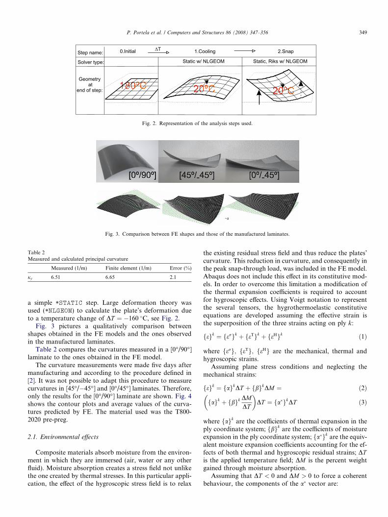
Fig. 2. Representation of the analysis steps used.
Fig. 3. Comparison between FE shapes and those of the manufactured laminates.
Table 2Measured and calculated principal curvature
Measured (1/m) Finite element (1/m) Error (%)
jy 6.51 6.65 2.1
P. Portela et al. / Computers and Structures 86 (2008) 347–356 349
a simple *STATIC step. Large deformation theory wasused (*NLGEOM) to calculate the plate’s deformation dueto a temperature change of DT ¼ �160 �C, see Fig. 2.
Fig. 3 pictures a qualitatively comparison betweenshapes obtained in the FE models and the ones observedin the manufactured laminates.
Table 2 compares the curvatures measured in a [0�/90�]laminate to the ones obtained in the FE model.
The curvature measurements were made five days aftermanufacturing and according to the procedure defined in[2]. It was not possible to adapt this procedure to measurecurvatures in [45�/�45�] and [0�/45�] laminates. Therefore,only the results for the [0�/90�] laminate are shown. Fig. 4shows the contour plots and average values of the curva-tures predicted by FE. The material used was the T800-2020 pre-preg.
2.1. Environmental effects
Composite materials absorb moisture from the environ-ment in which they are immersed (air, water or any otherfluid). Moisture absorption creates a stress field not unlikethe one created by thermal stresses. In this particular appli-cation, the effect of the hygroscopic stress field is to relax
the existing residual stress field and thus reduce the plates’curvature. This reduction in curvature, and consequently inthe peak snap-through load, was included in the FE model.Abaqus does not include this effect in its constitutive mod-els. In order to overcome this limitation a modification ofthe thermal expansion coefficients is required to accountfor hygroscopic effects. Using Voigt notation to representthe several tensors, the hygrothermoelastic constitutiveequations are developed assuming the effective strain isthe superposition of the three strains acting on ply k:
fegk ¼ fergk þ feTgk þ feHgk ð1Þ
where ferg; feTg; feHg are the mechanical, thermal andhygroscopic strains.
Assuming plane stress conditions and neglecting themechanical strains:
fegk ¼ fagkDT þ fbgkDM ¼ ð2Þ
fagk þ fbgk DMDT
� �DT ¼ fa�gkDT ð3Þ
where fagk are the coefficients of thermal expansion in theply coordinate system; fbgk are the coefficients of moistureexpansion in the ply coordinate system; fa�gk are the equiv-alent moisture expansion coefficients accounting for the ef-fects of both thermal and hygroscopic residual strains; DTis the applied temperature field; DM is the percent weightgained through moisture absorption.
Assuming that DT < 0 and DM > 0 to force a coherentbehaviour, the components of the a� vector are:
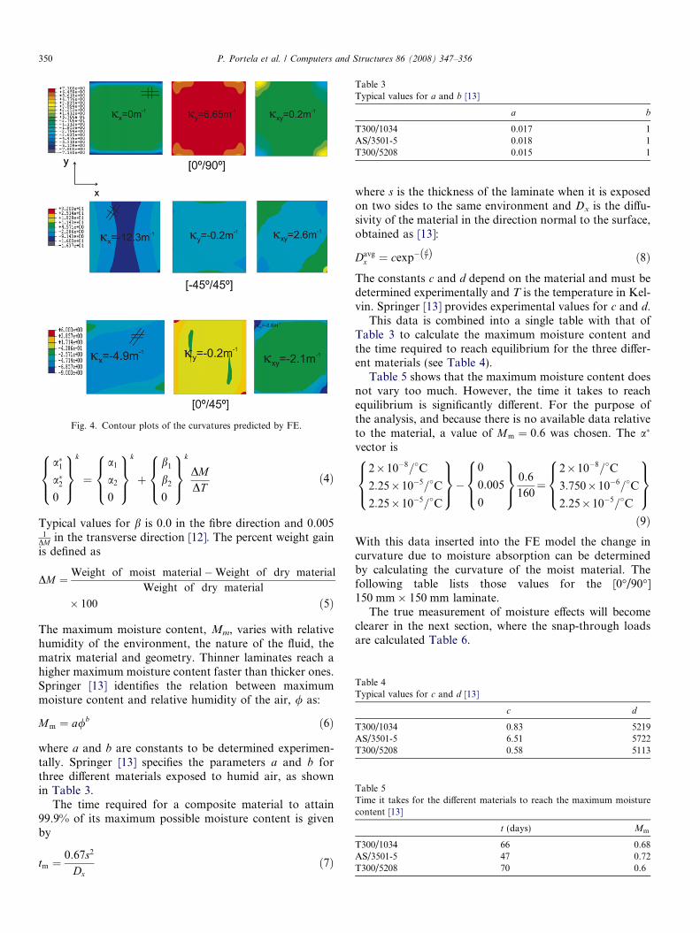
Fig. 4. Contour plots of the curvatures predicted by FE.
Table 3Typical values for a and b [13]
a b
T300/1034 0.017 1AS/3501-5 0.018 1T300/5208 0.015 1
Table 4Typical values for c and d [13]
c d
T300/1034 0.83 5219AS/3501-5 6.51 5722T300/5208 0.58 5113
Table 5Time it takes for the different materials to reach the maximum moisturecontent [13]
t (days) Mm
T300/1034 66 0.68AS/3501-5 47 0.72T300/5208 70 0.6
350 P. Portela et al. / Computers and Structures 86 (2008) 347–356
a�1a�20
8><>:
9>=>;
k
¼a1
a2
0
8><>:
9>=>;
k
þb1
b2
0
8><>:
9>=>;
k
DMDT
ð4Þ
Typical values for b is 0.0 in the fibre direction and 0.0051
DM in the transverse direction [12]. The percent weight gainis defined as
DM ¼Weight of moist material�Weight of dry material
Weight of dry material
� 100 ð5Þ
The maximum moisture content, Mm, varies with relativehumidity of the environment, the nature of the fluid, thematrix material and geometry. Thinner laminates reach ahigher maximum moisture content faster than thicker ones.Springer [13] identifies the relation between maximummoisture content and relative humidity of the air, / as:
Mm ¼ a/b ð6Þ
where a and b are constants to be determined experimen-tally. Springer [13] specifies the parameters a and b forthree different materials exposed to humid air, as shownin Table 3.
The time required for a composite material to attain99.9% of its maximum possible moisture content is givenby
tm ¼0:67s2
Dxð7Þ
where s is the thickness of the laminate when it is exposedon two sides to the same environment and Dx is the diffu-sivity of the material in the direction normal to the surface,obtained as [13]:
Davgx ¼ cexp�
dTð Þ ð8Þ
The constants c and d depend on the material and must bedetermined experimentally and T is the temperature in Kel-vin. Springer [13] provides experimental values for c and d.
This data is combined into a single table with that ofTable 3 to calculate the maximum moisture content andthe time required to reach equilibrium for the three differ-ent materials (see Table 4).
Table 5 shows that the maximum moisture content doesnot vary too much. However, the time it takes to reachequilibrium is significantly different. For the purpose ofthe analysis, and because there is no available data relativeto the material, a value of Mm ¼ 0:6 was chosen. The a�
vector is
2�10�8=�C
2:25�10�5=�C
2:25�10�5=�C
8><>:
9>=>;�
0
0:005
0
8><>:
9>=>;
0:6
160¼
2�10�8=�C
3:750�10�6=�C
2:25�10�5=�C
8><>:
9>=>;ð9Þ
With this data inserted into the FE model the change incurvature due to moisture absorption can be determinedby calculating the curvature of the moist material. Thefollowing table lists those values for the [0�/90�]150 mm� 150 mm laminate.
The true measurement of moisture effects will becomeclearer in the next section, where the snap-through loadsare calculated Table 6.
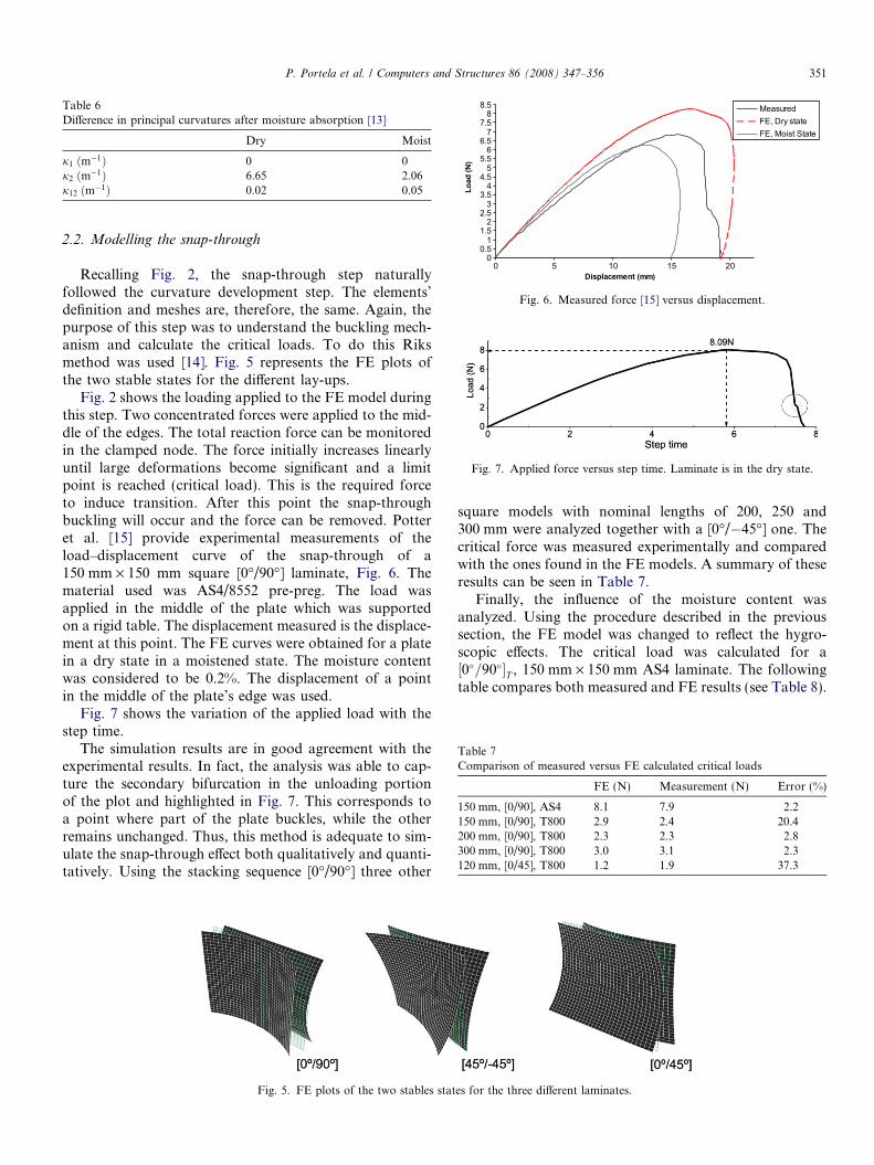
Table 6Difference in principal curvatures after moisture absorption [13]
Dry Moist
j1 ðm�1Þ 0 0j2 ðm�1Þ 6.65 2.06j12 ðm�1Þ 0.02 0.05
Fig. 6. Measured force [15] versus displacement.
Fig. 7. Applied force versus step time. Laminate is in the dry state.
Table 7Comparison of measured versus FE calculated critical loads
FE (N) Measurement (N) Error (%)
150 mm, [0/90], AS4 8.1 7.9 2.2150 mm, [0/90], T800 2.9 2.4 20.4200 mm, [0/90], T800 2.3 2.3 2.8300 mm, [0/90], T800 3.0 3.1 2.3120 mm, [0/45], T800 1.2 1.9 37.3
P. Portela et al. / Computers and Structures 86 (2008) 347–356 351
2.2. Modelling the snap-through
Recalling Fig. 2, the snap-through step naturallyfollowed the curvature development step. The elements’definition and meshes are, therefore, the same. Again, thepurpose of this step was to understand the buckling mech-anism and calculate the critical loads. To do this Riksmethod was used [14]. Fig. 5 represents the FE plots ofthe two stable states for the different lay-ups.
Fig. 2 shows the loading applied to the FE model duringthis step. Two concentrated forces were applied to the mid-dle of the edges. The total reaction force can be monitoredin the clamped node. The force initially increases linearlyuntil large deformations become significant and a limitpoint is reached (critical load). This is the required forceto induce transition. After this point the snap-throughbuckling will occur and the force can be removed. Potteret al. [15] provide experimental measurements of theload–displacement curve of the snap-through of a150 mm · 150 mm square [0�/90�] laminate, Fig. 6. Thematerial used was AS4/8552 pre-preg. The load wasapplied in the middle of the plate which was supportedon a rigid table. The displacement measured is the displace-ment at this point. The FE curves were obtained for a platein a dry state in a moistened state. The moisture contentwas considered to be 0.2%. The displacement of a pointin the middle of the plate’s edge was used.
Fig. 7 shows the variation of the applied load with thestep time.
The simulation results are in good agreement with theexperimental results. In fact, the analysis was able to cap-ture the secondary bifurcation in the unloading portionof the plot and highlighted in Fig. 7. This corresponds toa point where part of the plate buckles, while the otherremains unchanged. Thus, this method is adequate to sim-ulate the snap-through effect both qualitatively and quanti-tatively. Using the stacking sequence [0�/90�] three other
Fig. 5. FE plots of the two stables stat
square models with nominal lengths of 200, 250 and300 mm were analyzed together with a [0�/�45�] one. Thecritical force was measured experimentally and comparedwith the ones found in the FE models. A summary of theseresults can be seen in Table 7.
Finally, the influence of the moisture content wasanalyzed. Using the procedure described in the previoussection, the FE model was changed to reflect the hygro-scopic effects. The critical load was calculated for a½0�=90��T , 150 mm · 150 mm AS4 laminate. The followingtable compares both measured and FE results (see Table 8).
es for the three different laminates.
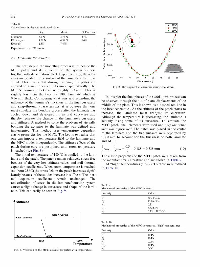
Table 8Critical loads in dry and moistened plates
Dry Moist % Decrease
Measured 7.9 N 4.73 N 67%FE analysis 8.09 N 4.38 N 84%Error (%) 2.4% 7.49% –
Experimental and FE results.
Fig. 9. Development of curvature during cool down.
Table 9Mechanical properties of the MFC actuator
352 P. Portela et al. / Computers and Structures 86 (2008) 347–356
2.3. Modelling the actuator
The next step in the modelling process is to include theMFC patch and its influence on the system stiffnesstogether with its actuation effect. Experimentally, the actu-ators are bonded to the surface of the laminate after it hascured. This means that during the cure, the plates areallowed to assume their equilibrium shape naturally. TheMFC’s nominal thickness is roughly 0.3 mm. This isslightly less than the two ply T800 laminate which is0.36 mm thick. Considering what was said regarding theinfluence of the laminate’s thickness in the final curvatureand snap-through characteristics, it is obvious that onemust simulate the bonding process after the laminate hascooled down and developed its natural curvature andthereby recreate the change in the laminate’s curvatureand stiffness. A method to solve the problem of virtuallybonding the actuator to the laminate was defined andimplemented. This method uses temperature dependentelastic properties for the MFC. The key is to realise thatone can impose a temperature field to the laminate andthe MFC model independently. The stiffness effects of thepatch during cure are postponed until room temperatureis reached (see Fig. 8).
The initial temperature of 180 �C is applied to the lam-inate and the patch. The patch remains relatively stress-freebecause of the very low stiffness values and null thermalexpansion coefficients. When room temperature is reached(at about 25 �C) the stress field in the patch increases signif-icantly because of the sudden increase in stiffness. The ther-mal expansion coefficients remain unchanged. Theredistribution of stress in the laminate/actuator systemcauses a slight change in curvature and shape of the lami-nate. This can easily be seen in Fig. 9.
Fig. 8. Variation of the MFC’s elastic properties with temperature.
In this plot the final phases of the cool down process canbe observed through the out of plane displacements of themiddle of the plate. This is shown as a dashed red line inthe inset schematic . As the stiffness of the patch starts toincrease, the laminate must readjust its curvature.Although the temperature is decreasing, the laminate isactually losing some of its curvature. To simulate theMFC patch, shell elements were used and only the active
area was represented. The patch was placed in the centreof the laminate and the two surfaces were separated by0.338 mm to account for the thickness of both laminateand MFC.
1
2tMFC þ
1
2tlam ¼
0:3
2þ 0:188 ¼ 0:338 mm ð10Þ
The elastic properties of the MFC patch were taken fromthe manufacturer’s literature and are shown in Table 9.
At ‘‘high’’ temperatures (T > 25 �C) these were reducedto Table 10.
Property Value
E1 30.34 GPaE2 15.86 GPam12 0.31G12 5.52 GPaa1 0:75� 10�6=�C
Table 10Mechanical properties of the MFC actuator at ‘‘high’’ temperatures
Property Value
E1 10 PaE2 10 Pam12 0.001G12 10 Paa1 0/�C
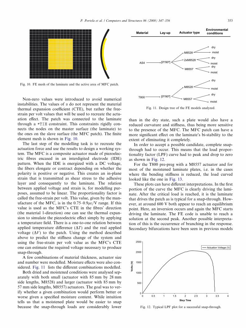
Fig. 10. FE mesh of the laminate and the active area of MFC patch.
Fig. 11. Design tree of the FE models analyzed.
Fig. 12. Typical LPF plot for a successful snap-through.
P. Portela et al. / Computers and Structures 86 (2008) 347–356 353
Non-zero values were introduced to avoid numericalinstabilities. The values of a do not represent the materialthermal expansion coefficient (CTE), but rather the free-strain per volt values that will be used to recreate the actu-ation effect. The patch was connected to the laminatethrough a *TIE constraint. This constraints rigidly con-nects the nodes on the master surface (the laminate) tothe ones on the slave surface (the MFC patch). The finiteelement mesh is shown in Fig. 10.
The last step of the modelling task is to recreate theactuation force and use the results to design a working sys-tem. The MFC is a composite actuator made of piezoelec-tric fibres encased in an interdigited electrode (IDE)pattern. When the IDE is energized with a DC voltage,the fibers elongate or contract depending on whether thepolarity is positive or negative. This creates an in-planestrain that is transmitted as shear stress to the adhesivelayer and consequently to the laminate. The relationbetween applied voltage and strain is, for modelling pur-poses, assumed to be linear. The proportionality factor iscalled the free-strain per volt. This value, given by the man-ufacture of the MFC, is in the 0:75–0:9le=V range. If thisvalue is used as the MFC’s CTE in the fibres’ direction(the material 1-direction) one can use the thermal expan-sion to simulate the piezoelectric effect simply by applyinga temperature field. There is a one-to-one relation betweenapplied temperature difference (DT ) and the real appliedvoltage (DV ) to the patch. Using the method describedabove to predict the stiffness change of the system andusing the free-strain per volt value as the MFC’s CTEone can estimate the required voltage necessary to producesnap-through.
A few combinations of material thickness, actuator sizeand number were modelled. Moisture effects were also con-sidered. Fig. 11 lists the different combinations modelled.
Both dried and moistened conditions were analysed sep-arately with both small (actuator with 85 mm by 28 mmside lengths, M8528) and larger (actuator with 85 mm by57 mm side lengths, M8557) actuators. The goal was to ver-ify whether a given combination would perform better orworse given a specified moisture content. While intuitiontells us that a moistened plate would be easier to snapbecause the snap-through loads are considerably lower
than in the dry state, such a plate would also have areduced curvature and stiffness, thus being more sensitiveto the presence of the MFC. The MFC patch can have amore significant effect on the laminate’s bi-stability to theextent of eliminating it completely.
In order to accept a possible candidate, complete snap-through had to occur. This means that the load propor-tionality factor (LPF) curve had to peak and drop to zeroas shown in Fig. 12.
For the T800 pre-preg with a M8557 actuator and formost of the moistened laminate plates, i.e. in the caseswhere the bending stiffness is reduced, the load curvedlooked like the one in Fig. 13.
These plots can have different interpretations. In the firstportion of the curve the MFC is clearly driving the lami-nate. After the critical load is reached, it is the laminatethat drives the patch as is typical for a snap-through. How-ever, at around 600 V both appear to reach an equilibriumpoint. Here, an inversion occurs and again the MFC startsdriving the laminate. The FE code is unable to reach asolution at the second peak. Another possible interpreta-tion of this is the occurrence of branching in the response.Secondary bifurcations have been seen in previous models
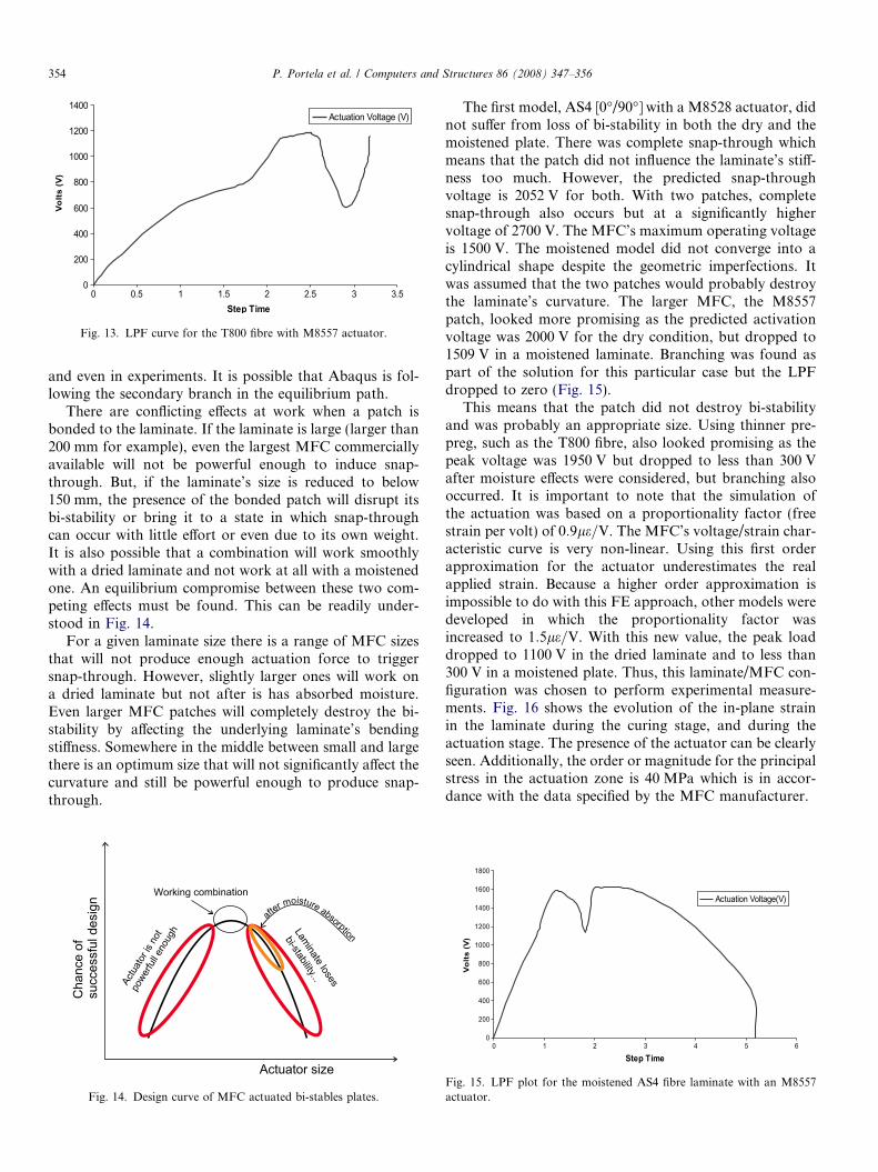
Fig. 13. LPF curve for the T800 fibre with M8557 actuator.
354 P. Portela et al. / Computers and Structures 86 (2008) 347–356
and even in experiments. It is possible that Abaqus is fol-lowing the secondary branch in the equilibrium path.
There are conflicting effects at work when a patch isbonded to the laminate. If the laminate is large (larger than200 mm for example), even the largest MFC commerciallyavailable will not be powerful enough to induce snap-through. But, if the laminate’s size is reduced to below150 mm, the presence of the bonded patch will disrupt itsbi-stability or bring it to a state in which snap-throughcan occur with little effort or even due to its own weight.It is also possible that a combination will work smoothlywith a dried laminate and not work at all with a moistenedone. An equilibrium compromise between these two com-peting effects must be found. This can be readily under-stood in Fig. 14.
For a given laminate size there is a range of MFC sizesthat will not produce enough actuation force to triggersnap-through. However, slightly larger ones will work ona dried laminate but not after is has absorbed moisture.Even larger MFC patches will completely destroy the bi-stability by affecting the underlying laminate’s bendingstiffness. Somewhere in the middle between small and largethere is an optimum size that will not significantly affect thecurvature and still be powerful enough to produce snap-through.
Actuator size
Cha
nce
ofsu
cces
sful
des
ign
Laminate loses
bi-stability...Actu
ator
is n
ot
powe
rfull e
noug
h
...
after moisture abso pr tion
Working combination
Fig. 14. Design curve of MFC actuated bi-stables plates.
The first model, AS4 [0�/90�] with a M8528 actuator, didnot suffer from loss of bi-stability in both the dry and themoistened plate. There was complete snap-through whichmeans that the patch did not influence the laminate’s stiff-ness too much. However, the predicted snap-throughvoltage is 2052 V for both. With two patches, completesnap-through also occurs but at a significantly highervoltage of 2700 V. The MFC’s maximum operating voltageis 1500 V. The moistened model did not converge into acylindrical shape despite the geometric imperfections. Itwas assumed that the two patches would probably destroythe laminate’s curvature. The larger MFC, the M8557patch, looked more promising as the predicted activationvoltage was 2000 V for the dry condition, but dropped to1509 V in a moistened laminate. Branching was found aspart of the solution for this particular case but the LPFdropped to zero (Fig. 15).
This means that the patch did not destroy bi-stabilityand was probably an appropriate size. Using thinner pre-preg, such as the T800 fibre, also looked promising as thepeak voltage was 1950 V but dropped to less than 300 Vafter moisture effects were considered, but branching alsooccurred. It is important to note that the simulation ofthe actuation was based on a proportionality factor (freestrain per volt) of 0:9le=V. The MFC’s voltage/strain char-acteristic curve is very non-linear. Using this first orderapproximation for the actuator underestimates the realapplied strain. Because a higher order approximation isimpossible to do with this FE approach, other models weredeveloped in which the proportionality factor wasincreased to 1:5le=V. With this new value, the peak loaddropped to 1100 V in the dried laminate and to less than300 V in a moistened plate. Thus, this laminate/MFC con-figuration was chosen to perform experimental measure-ments. Fig. 16 shows the evolution of the in-plane strainin the laminate during the curing stage, and during theactuation stage. The presence of the actuator can be clearlyseen. Additionally, the order or magnitude for the principalstress in the actuation zone is 40 MPa which is in accor-dance with the data specified by the MFC manufacturer.
Fig. 15. LPF plot for the moistened AS4 fibre laminate with an M8557actuator.
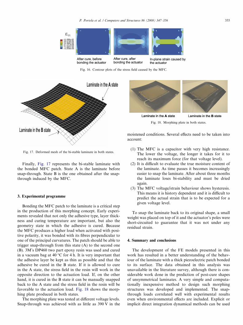
Fig. 16. Contour plots of the stress field caused by the MFC.
Fig. 17. Deformed mesh of the bi-stable laminate in both states.
Fig. 18. Morphing plate in both states.
P. Portela et al. / Computers and Structures 86 (2008) 347–356 355
Finally, Fig. 17 represents the bi-stable laminate withthe bonded MFC patch. State A is the laminate beforesnap-through. State B is the one obtained after the snap-through induced by the MFC.
3. Experimental programme
Bonding the MFC patch to the laminate is a critical stepin the production of this morphing concept. Early experi-ments revealed that not only the adhesive type, layer thick-ness and curing temperature are important, but also thegeometry state in which the adhesive is cured. Becausethe MFC produces a higher load when activated with posi-tive polarity, it was bonded with its fibres perpendicular toone of the principal curvatures. The patch should be able totrigger snap-through from this state (A) to the second one(B). 3M’s DP460 two part epoxy resin was used and curedin a vacuum bag at 40 �C for 4 h. It is very important thatthe adhesive layer be kept as thin as possible and that theadhesive be cured in the B state. If it is allowed to curein the A state, the stress field in the resin will work in theopposite direction to the actuation load. If, on the otherhand, it is cured in the B state it can be manually snappedback to the A state and the stress field in the resin will befavorable to the actuation load. Fig. 18 shows the morp-hing plate produced in both states.
The morphing plate was tested at different voltage levels.Snap-through was achieved with as little as 390 V in the
moistened conditions. Several effects need to be taken intoaccount:
(1) The MFC is a capacitor with very high resistance.The lower the voltage, the longer it takes for it toreach its maximum force (for that voltage level).
(2) It is difficult to evaluate the true moisture content ofthe laminate. As time passes it becomes increasinglyeasier to snap the laminate. After about three monthsthe laminate loses bi-stability and must be driedagain.
(3) The MFC voltage/strain behaviour shows hysteresis.This means it is history dependent and it is difficult topredict the actual strain that is to be expected for agiven voltage level.
To snap the laminate back to its original shape, a smallweight was placed on top of it and the actuator’s poles wereshort-circuited to guarantee that it was not under anyresidual strain.
4. Summary and conclusions
The development of the FE models presented in thiswork has resulted in a better understanding of the behav-iour of the laminate with a thick piezoelectric patch bondedto its surface. The data obtained in this analysis wasunavailable in the literature survey, although there is con-siderable work done in the prediction of post-cure shapesof unsymmetrical laminates. A very simple and computa-tionally inexpensive method to design such morphingstructures was developed and implemented. The snap-through loads correlated well with experimental resultseven when environmental effects are included. Explicit orimplicit direct integration dynamical methods can be used
356 P. Portela et al. / Computers and Structures 86 (2008) 347–356
to predict post cure shapes of laminates without the need ofartificial geometric imperfections. Although it is possible todesign working active bi-stable laminates based on MFCactuators and to understand their behaviour, the low actu-ator force still limits the size of the bi-stable laminate. Theeffect it has on the laminate’s stiffness and curvature is alsoconsiderable. Because of this effect the laminate loses itssymmetry, and it becomes much more difficult to snap itback from state B to state A manually and impossible todo so with the actuator. Tests were performed on the activelaminate but with no success. Thus, it is difficult to designan MFC based actuator that is able to snap the laminateboth ways, which is the ultimate objective of these studies.The most promising actuation method is one that does notinfluence the geometry of the laminate.
Acknowledgement
The financial support of the Portuguese Science Foun-dation (FCT) through the Grant SFRHnBMn16199n2004is gratefully acknowledged by the first author.
References
[1] Jha AK, Kudva JN. Morphing aircraft concepts, classifications andchallenges. Proc SPIE 2004;5388.
[2] Schultz MR. Use of piezoelectric actuators to effect snap-throughbehavior of unsymmetric composite laminates. Ph.D. thesis, VirginiaPolytechnic Institute and State University; 2003.
[3] Schultz MR, Hyer MW. A morphing concept based on unsymmetriccomposite laminates and piezoceramic MFC actuators. In: Proceed-ings of the 45th AIAA/ASME/ASCE/AHS/ASC structures, struc-tural dynamics and materials conference; 2004.
[4] Williams RB, Inman DJ. An overview of composite actuators withpiezoceramic fibres, unpublished.
[5] Dano ML, Hyer MW. SMA-induced snap-through of unsymmetricfiber-reinforced composite laminates. Int J Solids Struct 2003;40:5949–72.
[6] Hufenbach W, Gude M, Kroll L. Design of multistable compositesfor application in adaptive structures. Compos Sci Technol 2002:2201–7.
[7] Hufenbach W, Gude M. Analysis and optimisation of multistablecomposites under residual stresses. Compos Struct 2002;55:319–27.
[8] Dano ML, Hyer MW. Thermally-induced deformation behavior ofunsymmetric laminates. Int J Solids Struct 1998;35:2101–20.
[9] Schlecht M, Schulte K, Hyer MW. Advanced calculation of theroom-temperature shapes of thin unsymmetric composite laminates.Compos Struct 1995;32:627–33.
[10] Gigliotti M, Wisnom MR, Potter KD. Loss of bifurcation andmultiple shapes of thin [0/90] unsymmetric composite plates subjectto thermal stress. Compos Sci Technol 2004;64:109–28.
[11] Portela PM. Analysis and optimization of morphing, multi-stablestructures actuated by piezoelectric patches. M.Sc. thesis, Faculdadede Engenharia da Universidade do Porto; 2005.
[12] Herakovich CT. Mechanics of fibrous composites. John Wiley andSons Inc; 1998.
[13] Springer GS. Environmental effects on composite materials. Tech-nomic Publishing Company; 1981.
[14] Abaqus 6.4 User’s Manuals, Abaqus, Inc.; 2004.[15] Potter K, Weaver PM, Seman AA, Shah S. Phenomena in the snap-
through bifurcation of unsymmetric composite plates. Compos PartA 2007;38:100–6.

![Aerospace Science and Technology...tests of a morphing wing built by using compliant mechanisms and piezoelectric actuators. In Nguyen et al. [6]the principles of aerodynamic shape](https://img.pdfslide.us/doc/110x75/6100d1a0d699ac556a391526/aerospace-science-and-technology-tests-of-a-morphing-wing-built-by-using-compliant.jpg)