Embed Size (px)
Citation preview
Journal of Energy and Power Engineering 12 (2018) 553-564 doi: 10.17265/1934-8975/2018.12.001
Analysis of Mechanical Combined-Type CVT Consisting of Closed Links, Grooved Cam and Non-invertible
Elements
Toshihiro Yukawa1, Takuto Yoshikawa2 and Naoya Matsumoto2 1. Faculty of Science and Engineering, Iwate University, 4-3-5 Ueda, Morioka, Iwate 020-8551, Japan
2. Graduate School of Engineering, Iwate University, 4-3-5 Ueda, Morioka, Iwate 020-8551, Japan Abstract: As one of transmission mechanisms, continuously variable transmission (CVT) can transfer energy depending upon rotation speed or torque generated by rotation power transferred from input axis to output axis. It is known that the CVT is mechanism that can change gear ratios continuously in power transmission installed in vehicles, or power generation and its transfer systems. In this paper, we propose a CVT using a new type of mechanism in which four-bar linkages (quadric crank chains) and non-invertible elements such as one-way clutches or ratchets are installed. The conventional CVTs which are classified as belt-type CVTs or toroidal CVTs are driven by friction force between conduction mechanisms. Due to slippage or high-pressure between the transmission components in the conduction mechanism, the transfer efficiency in the conduction energy becomes inferior. However, the proposed CVT does not depend upon any friction forces, and it is considered that its transfer efficiency is superior. Key words: CVT, closed link, four-bar linkage, lever-crank mechanism, one-way clutch, power efficiency, friction, tribology.
1. Introduction
Nowadays, clean and safe sources of energy have been reviewed for creating sustainable society. For the realization of such a society, the technology for fuel-efficient transportations and electric generation etc. is referred as one of the important issues.
As one of the technologies, we consider about a power transmission and a continuously variable transmission (CVT) with high energy transfer efficiency. The proposed transmission is composed of simple mechanical parts, and has high energy transfer efficiency in principle compared with the conventional system. The CVT transfers rotation energy while changing rotation speed transferred from input axis to output axis. The transmission power between the input and output sides in transmission mechanism is changed by not only angular velocity, but also angular acceleration in rotation axes.
Corresponding author: Toshihiro Yukawa, Ph.D., associate
professor, research fields: mechanics, robotics, CVT.
In this paper, a mechanically combined type CVT consisting of closed loop links connected at each joint, and elements which yield non-invertible motion are explained. This conduction mechanism does not especially need to deal with friction conditions, excepting that the bearing is installed at each joint of the link mechanism. Assuming that the friction coefficient for rolling friction generated in the bearing is small, it can be neglected in this paper. Since the mechanism can provide advantage for creating no slip between conduction mechanisms under a constrained condition, the proposed design can maintain high transmission efficiency.
In this paper, to confirm the fundamental characteristics of the CVT we modify the proposed mechanical CVT as an experimental setup which consists of mechanical components with additional motor controlled electrically. The CVT as experimental setup has a shifting mechanism to change a gear ratio by sliding motion of a slide rail mounted on each link. The length of each link can be controlled by a motor.
D DAVID PUBLISHING

Analysis of Mechanical Combined-Type CVT Consisting of Closed Links, Grooved Cam and Non-invertible Elements
554
About the conventional transmission, there are several types of transmissions and CVTs. A most typical transmission is composed of spur gear series and a crutch mechanism which can switch between on and off the transmission of the power in vehicles, etc.
The CVTs have been classified mainly as belt-type CVTs or toroidal CVTs. Each CVT is composed of several frictional components in the mechanism to transmit the conduction power generated by the input power through the input axis. For these CVTs, the transfer efficiency becomes low due to slippage phenomenon or load by high-pressure between conduction mechanisms.
Especially in this paper, we analyze the performance of the proposed linkage-type CVT, and discuss the control method for expansion and contraction of the links in the proposed CVT. Also, we examine the efficiency of the CVT as power train in the transmission.
As conventional studies for the CVTs, many researchers have been studying the theory, analysis, development, and control method. N. Sadegh et al. [1] have developed a continuous-time model and controller for the drivetrain dynamics and hydraulics governing the ratio dynamics of a metal V-belt CVT. B. Bonsen et al. [2] have analyzed a slip in a CVT by measuring the traction curve in a V-belt CVT, and quantitative evaluations were done. T. Klaassen et al. [3] have proposed a control method that stabilizes the slip in the variator. The new system could be identified at various slip speed levels, including macro-slip levels. Also, they designed the primary speed of the CVT using the proposed feedback control [3]. R. J. Pulles et al. [4] have developed a CVT with a slip controller that gives a high efficiency at low engine torques in a car. S. Akehurst et al. [5] have developed the Milner continuously variable transmission (MCVT) which is a traction drive transmission based on rolling contacts analogous to those found in angular contact roller bearings. The MCVT is a rolling traction drive transmission
consisting of three independent rolling elements, the inner races, the outer races and the planet/carrier assembly [5]. K. A. Tahboub et al. [6] have designed an omnidirectional vehicle in which the ball-based foot-print configurable CVT vehicle was mounted. L. Mangialardi et al. [7] have examined the feasibility of using a CVT in wind power systems producing electric energy to be delivered directly to the mains. Also, they have simulated a system consisting of a horizontal axis wind turbine connected to an induction generator by a belt type CVT using their proposed mathematical model [7]. Furthermore, they have examined the dynamic behavior of a wind power system for the generation of electrical energy equipped with an automatically regulated V-belt CVT [8]. D. Petkovic et al. [9] have designed a novel intelligent controller based on the adaptive neuro-fuzzy inference system (ANFIS) in order to maintain the maximal output power of wind turbine. Also, they have proposed a wind generator equipped with CVT to improve the wind energy available in an erratic wind speed regime [9]. For other studies for the CVTs, see [10-15].
Furthermore, in the study of robot as other areas, Takagi et al. [16] have studied that the link structure for use in the hand of the robot is regarded as a CVT structure, and they have analyzed it in order to achieve a high payload. K. Tadakuma et al. [17] have developed a linear load-sensitive CVT with a spherical driving unit. This CVT mechanism consists of a spherical drive, drive axis, motor housing, fixed bracket, and a linear sliding plate. It continuously changes the reduction ratio by changing the inclination angle of the active rotational axis. Additionally, this linear mechanism ensures load-sensitive functioning by changing the inclination of the active rotational axis in response to the load [17]. M. Higuchi [18] has developed a new robotic assist device; a passive assist arm (PAS-Arm). PAS-Arms are intended for direct physical interaction with a human operator, handling a shared payload.
Analysis of Mechanical Combined-Type CVT Consisting of Closed Links, Grooved Cam and Non-invertible Elements
555
PAS-Arms have three joints and a three-dimensional workspace, but possess only two degrees of freedom, due to the reduction of degrees of freedom created by a combination of CVTs and differential gears [18]. J. Yuan and S. Hirose [19] have developed a novel linear motion mechanism with load sensitive transmission, which consists of certain key components such as rubber rollers and flat springs. The developed mechanical model provides long stroke linear motion and has its ratio changed automatically in response to the continuously variable coaxial pressing load. This compact mechanism has the ability to absorb sudden coaxial load shock and is equipped with overload protection [19]. Also, S. Hirose et al. [20] have designed an in-pipe inspection vehicle for pipes, “Theseuse” series. They introduced the concept “Whole Stem Drive”. This concept was effective to allow an in-pipe vehicle to travel long distance in the pipeline. Based on this concept, they have made three in-pipe vehicles. They have proposed two mechanisms, in-pipe vehicle with spiral motion (Theseus-I) and in-pipe vehicle for the practical gas pipe. Also, they have proposed the in-pipe vehicle based on the idea of Control Configured Vehicle (CCV), Theseus-III for the pipe with 150 mm in diameter. Furthermore, they have proposed the in-pipe vehicle which had an actuator outside of the pipe (Theseus-IV) [20].
2. Linkage Type CVT
2.1 Link Length Relationship
The proposed linkage type CVT is mainly composed of four-bar linkages (quadric crank chains) with motors, rack gears, spur gear and slide rails. As the mathematical study of linkages, C. G. Gibson et al. [21] have examined the geometry of a simple engineering mechanism, comprising four bars smoothly jointed together to form a movable quadrilateral with one fixed side [21]. For the movement of the four-bar linkages, it is divided into four types; i.e., double-crank (drag-link), crank-rocker (lever-crank), double-rocker and parallelogram linkage. Among these four types, we
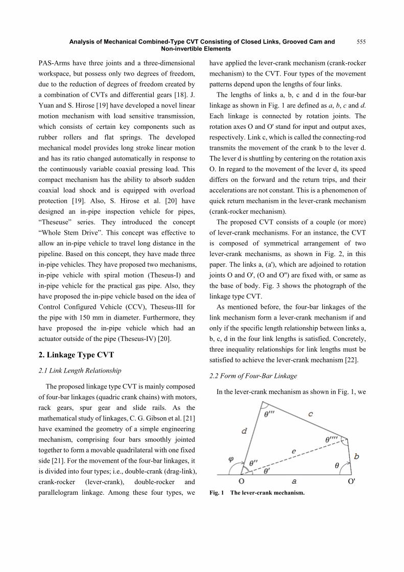
have applied the lever-crank mechanism (crank-rocker mechanism) to the CVT. Four types of the movement patterns depend upon the lengths of four links.
The lengths of links a, b, c and d in the four-bar linkage as shown in Fig. 1 are defined as a, b, c and d. Each linkage is connected by rotation joints. The rotation axes O and O' stand for input and output axes, respectively. Link c, which is called the connecting-rod transmits the movement of the crank b to the lever d. The lever d is shuttling by centering on the rotation axis O. In regard to the movement of the lever d, its speed differs on the forward and the return trips, and their accelerations are not constant. This is a phenomenon of quick return mechanism in the lever-crank mechanism (crank-rocker mechanism).
The proposed CVT consists of a couple (or more) of lever-crank mechanisms. For an instance, the CVT is composed of symmetrical arrangement of two lever-crank mechanisms, as shown in Fig. 2, in this paper. The links a, (a'), which are adjoined to rotation joints O and O', (O and O'') are fixed with, or same as the base of body. Fig. 3 shows the photograph of the linkage type CVT.
As mentioned before, the four-bar linkages of the link mechanism form a lever-crank mechanism if and only if the specific length relationship between links a, b, c, d in the four link lengths is satisfied. Concretely, three inequality relationships for link lengths must be satisfied to achieve the lever-crank mechanism [22].
2.2 Form of Four-Bar Linkage
In the lever-crank mechanism as shown in Fig. 1, we
Fig. 1 The lever-crank mechanism.

Analysis of Mechanical Combined-Type CVT Consisting of Closed Links, Grooved Cam and Non-invertible Elements
556
Fig. 2 The linkage type CVT.
Fig. 3 Photo of the linkage type CVT.
define angles between links as θ, θ', θ'', θ''' and θ''''. The length of the virtual link e connecting the rotation joint O of link d, and a tip of the crank b is defined as e. Four kinds of angles θ', θ'', θ''' and θ'''' can be determined using the values of an input angle θ, and four link lengths a, b, c and d. For the situation where the connecting-rod c is being connected to the crank b when both b and c links form a straight line, it is called as dead point. Let the angle θ be θ1 when θ''' is equal to the maximum value. Also, let the angle θ be θ2 when θ''' is equal to the minimum value. At the moment when the four-bar linkages are in the situation with the dead point, that is, θ = θ1, and θ = θ2, the direction of reciprocating motion of the output link (lever) d is just switched. For the motion of the link (lever) d, it is referred as a forward path in the range of θ1 < θ < θ2, otherwise as a return path in the range of
0 < θ < θ1, or θ2 < θ < 2π. Using law of cosines, e, θ', and θ'' can be expressed
as follows:
θcos222 abbae −+= (1)
aebea
2cos
2221 −+
=′ −θ (2)
deced
2cos
2221 −+
=′′ −θ (3)
Using Eqs. (1)-(3), for each phase of θ, φ and φs are given by
(i) ππθπ +<≤ nn 22 (n = 0, 1, 2, ...)
θθπϕ ′′+′−= (4)
(ii) ππθππ 222 +<≤+ nn (n = 0, 1, 2, ...)
θθπϕ ′′+′+= (5)
and
Rsθϕ = (6)
For each phase of θ, both θ'' and c can be expressed as follows:
(i) ππθπ +<≤ nn 22 (n = 0, 1, 2, ...)
sϕθπθ −′−=′′ (7) (ii) ππθππ 222 +<≤+ nn (n = 0, 1, 2, ...)
sϕθπθ −′+=′′ (8)
and
θ ′′−+= cos222 deedc (9)
Fig. 4 shows the angular velocity output by the two pairs of the four-bar linkage obtained from Eqs. (7) and (8) in case that all lengths of the four links do not change.
2.3 Forces Which Are Applied to Input and Output Links
We here discuss the relationship between the forces and torques transmitted to the output axis O from the input axes O', (O''), as shown in Fig. 5, through the connecting-rods c and c'. We focus only one set of
Analysis of Mechanical Combined-Type CVT Consisting of Closed Links, Grooved Cam and Non-invertible Elements
557
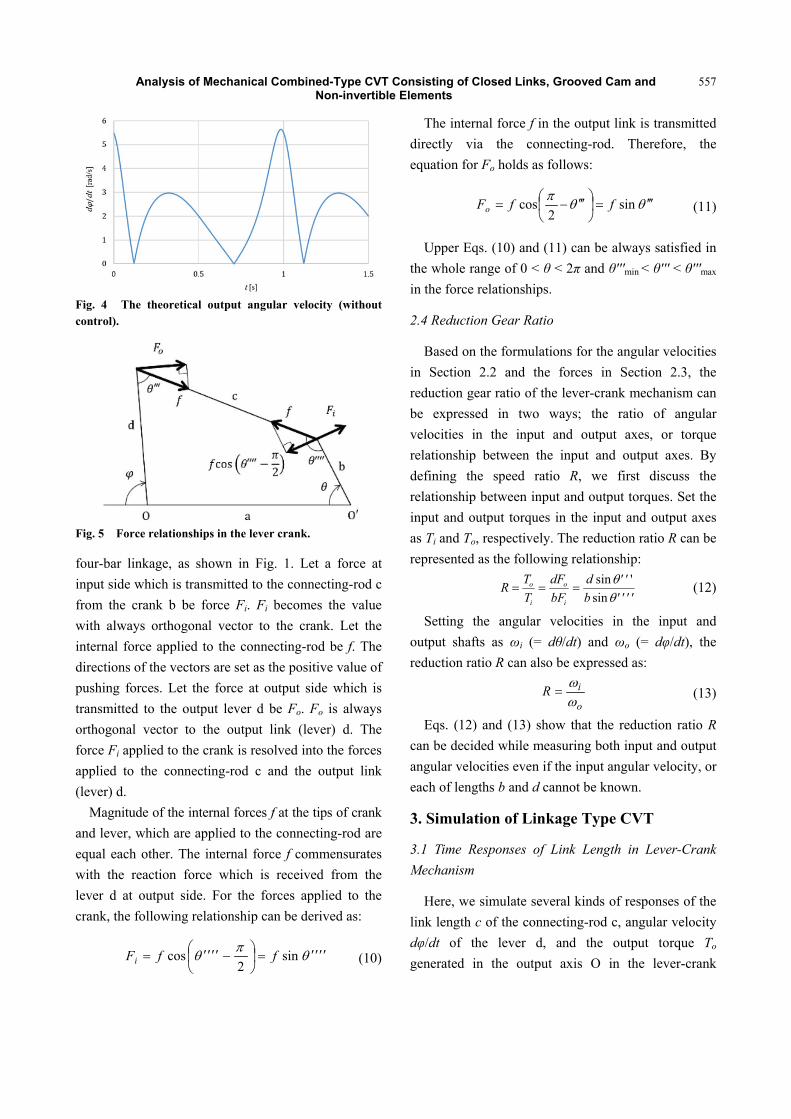
Fig. 4 The theoretical output angular velocity (without control).
Fig. 5 Force relationships in the lever crank.
four-bar linkage, as shown in Fig. 1. Let a force at input side which is transmitted to the connecting-rod c from the crank b be force Fi. Fi becomes the value with always orthogonal vector to the crank. Let the internal force applied to the connecting-rod be f. The directions of the vectors are set as the positive value of pushing forces. Let the force at output side which is transmitted to the output lever d be Fo. Fo is always orthogonal vector to the output link (lever) d. The force Fi applied to the crank is resolved into the forces applied to the connecting-rod c and the output link (lever) d.
Magnitude of the internal forces f at the tips of crank and lever, which are applied to the connecting-rod are equal each other. The internal force f commensurates with the reaction force which is received from the lever d at output side. For the forces applied to the crank, the following relationship can be derived as:
θπθ ′′′′=⎟⎠⎞
⎜⎝⎛ −′′′′= sin
2cos ffFi (10)
The internal force f in the output link is transmitted directly via the connecting-rod. Therefore, the equation for Fo holds as follows:
θθπ ′′′=⎟⎠⎞
⎜⎝⎛ ′′′−= sin
2cos ffFo (11)
Upper Eqs. (10) and (11) can be always satisfied in the whole range of 0 < θ < 2π and θ'''min < θ''' < θ'''max in the force relationships.
2.4 Reduction Gear Ratio
Based on the formulations for the angular velocities in Section 2.2 and the forces in Section 2.3, the reduction gear ratio of the lever-crank mechanism can be expressed in two ways; the ratio of angular velocities in the input and output axes, or torque relationship between the input and output axes. By defining the speed ratio R, we first discuss the relationship between input and output torques. Set the input and output torques in the input and output axes as Ti and To, respectively. The reduction ratio R can be represented as the following relationship:
''''b''d
bFdF
TTR
i
o
i
o
θθ
sin'sin
=== (12)
Setting the angular velocities in the input and output shafts as ωi (= dθ/dt) and ωo (= dφ/dt), the reduction ratio R can also be expressed as:
o
iRωω
= (13)
Eqs. (12) and (13) show that the reduction ratio R can be decided while measuring both input and output angular velocities even if the input angular velocity, or each of lengths b and d cannot be known.
3. Simulation of Linkage Type CVT
3.1 Time Responses of Link Length in Lever-Crank Mechanism
Here, we simulate several kinds of responses of the link length c of the connecting-rod c, angular velocity dφ/dt of the lever d, and the output torque To generated in the output axis O in the lever-crank
Analysis of Mechanical Combined-Type CVT Consisting of Closed Links, Grooved Cam and Non-invertible Elements
558
mechanism shown in Figs. 2 and 3. Also, comparing with the simulated responses, we discuss the experimental results in responses of the link length c of the connecting-rod c, and angular velocity dφ/dt of the lever d.
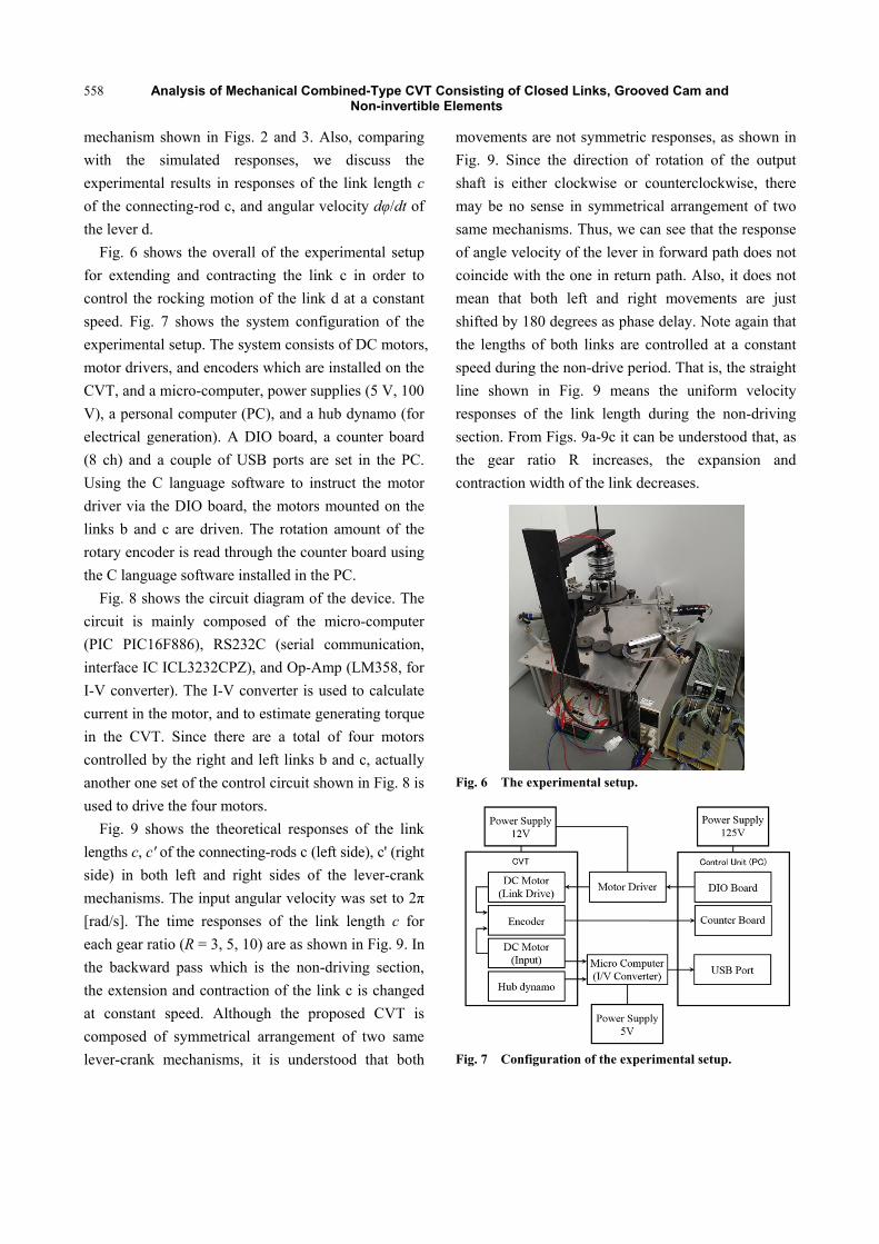
Fig. 6 shows the overall of the experimental setup for extending and contracting the link c in order to control the rocking motion of the link d at a constant speed. Fig. 7 shows the system configuration of the experimental setup. The system consists of DC motors, motor drivers, and encoders which are installed on the CVT, and a micro-computer, power supplies (5 V, 100 V), a personal computer (PC), and a hub dynamo (for electrical generation). A DIO board, a counter board (8 ch) and a couple of USB ports are set in the PC. Using the C language software to instruct the motor driver via the DIO board, the motors mounted on the links b and c are driven. The rotation amount of the rotary encoder is read through the counter board using the C language software installed in the PC.
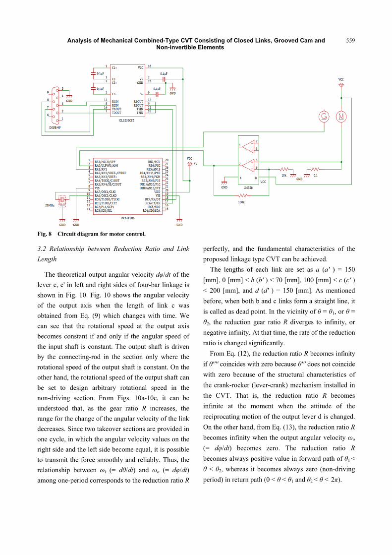
Fig. 8 shows the circuit diagram of the device. The circuit is mainly composed of the micro-computer (PIC PIC16F886), RS232C (serial communication, interface IC ICL3232CPZ), and Op-Amp (LM358, for I-V converter). The I-V converter is used to calculate current in the motor, and to estimate generating torque in the CVT. Since there are a total of four motors controlled by the right and left links b and c, actually another one set of the control circuit shown in Fig. 8 is used to drive the four motors.
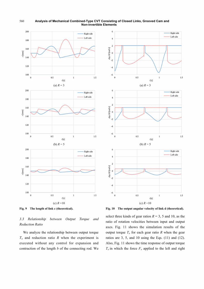
Fig. 9 shows the theoretical responses of the link lengths c, c' of the connecting-rods c (left side), c' (right side) in both left and right sides of the lever-crank mechanisms. The input angular velocity was set to 2π [rad/s]. The time responses of the link length c for each gear ratio (R = 3, 5, 10) are as shown in Fig. 9. In the backward pass which is the non-driving section, the extension and contraction of the link c is changed at constant speed. Although the proposed CVT is composed of symmetrical arrangement of two same lever-crank mechanisms, it is understood that both
movements are not symmetric responses, as shown in Fig. 9. Since the direction of rotation of the output shaft is either clockwise or counterclockwise, there may be no sense in symmetrical arrangement of two same mechanisms. Thus, we can see that the response of angle velocity of the lever in forward path does not coincide with the one in return path. Also, it does not mean that both left and right movements are just shifted by 180 degrees as phase delay. Note again that the lengths of both links are controlled at a constant speed during the non-drive period. That is, the straight line shown in Fig. 9 means the uniform velocity responses of the link length during the non-driving section. From Figs. 9a-9c it can be understood that, as the gear ratio R increases, the expansion and contraction width of the link decreases.
Fig. 6 The experimental setup.
Fig. 7 Configuration of the experimental setup.
Analysis of Mechanical Combined-Type CVT Consisting of Closed Links, Grooved Cam and Non-invertible Elements
559
Fig. 8 Circuit diagram for motor control.
3.2 Relationship between Reduction Ratio and Link Length
The theoretical output angular velocity dφ/dt of the lever c, c' in left and right sides of four-bar linkage is shown in Fig. 10. Fig. 10 shows the angular velocity of the output axis when the length of link c was obtained from Eq. (9) which changes with time. We can see that the rotational speed at the output axis becomes constant if and only if the angular speed of the input shaft is constant. The output shaft is driven by the connecting-rod in the section only where the rotational speed of the output shaft is constant. On the other hand, the rotational speed of the output shaft can be set to design arbitrary rotational speed in the non-driving section. From Figs. 10a-10c, it can be understood that, as the gear ratio R increases, the range for the change of the angular velocity of the link decreases. Since two takeover sections are provided in one cycle, in which the angular velocity values on the right side and the left side become equal, it is possible to transmit the force smoothly and reliably. Thus, the relationship between ωi (= dθ/dt) and ωo (= dφ/dt) among one-period corresponds to the reduction ratio R
perfectly, and the fundamental characteristics of the proposed linkage type CVT can be achieved.
The lengths of each link are set as a (a' ) = 150 [mm], 0 [mm] < b (b' ) < 70 [mm], 100 [mm] < c (c' ) < 200 [mm], and d (d' ) = 150 [mm]. As mentioned before, when both b and c links form a straight line, it is called as dead point. In the vicinity of θ = θ1, or θ = θ2, the reduction gear ratio R diverges to infinity, or negative infinity. At that time, the rate of the reduction ratio is changed significantly.
From Eq. (12), the reduction ratio R becomes infinity if θ'''' coincides with zero because θ''' does not coincide with zero because of the structural characteristics of the crank-rocker (lever-crank) mechanism installed in the CVT. That is, the reduction ratio R becomes infinite at the moment when the attitude of the reciprocating motion of the output lever d is changed. On the other hand, from Eq. (13), the reduction ratio R becomes infinity when the output angular velocity ωo (= dφ/dt) becomes zero. The reduction ratio R becomes always positive value in forward path of θ1 < θ < θ2, whereas it becomes always zero (non-driving period) in return path (0 < θ < θ1 and θ2 < θ < 2π).
Analysis of Mechanical Combined-Type CVT Consisting of Closed Links, Grooved Cam and Non-invertible Elements
560
(a) R = 3
(b) R = 5
(c) R =10
Fig. 9 The length of link c (theoretical).
3.3 Relationship between Output Torque and Reduction Ratio
We analyze the relationship between output torque To and reduction ratio R when the experiment is executed without any control for expansion and contraction of the length b of the connecting rod. We
(a) R = 3
(b) R = 5
(c) R =10
Fig. 10 The output angular velocity of link d (theoretical).
select three kinds of gear ratios R = 3, 5 and 10, as the ratio of rotation velocities between input and output axes. Fig. 11 shows the simulation results of the output torque To for each gear ratio R when the gear ratios are 3, 5, and 10 using the Eqs. (11) and (12). Also, Fig. 11 shows the time response of output torque To in which the force Fo applied to the left and right

Analysis of Mechanical Combined-Type CVT Consisting of Closed Links, Grooved Cam and Non-invertible Elements
561
(a) R = 3
(b) R = 5
(c) R =10
Fig. 11 Combined torque generated by dual lever crank mechanism.
links d. The input torque Ti is set as 1.0 [Nm], and the angular velocity ωi (= dθ/dt) of the input axis as 2π [rad/s]. From Eqs. (12) and (13), and angle relationship in the lever crank mechanism as shown in Fig. 1, when the angle of crank θ is positioned in the vicinity of θ'''' = 0 [rad], the value of R becomes to infinity, and also the output torque To becomes to plus, or minus infinity. Fig. 11 shows the simulation results
for the output torque To; (a) the output torque ToutR of the right side of lever-crank mechanism, (b) the output torque ToutL of the left side of lever-crank mechanism, and (c) the unidirectional (positive value side) torque in which (a) torque on the right side and (b) torque on the left side are overlapped. It can also be seen that the torque To (absolute value of minimum and maximum values of ToutR and ToutL) is increased in proportion to the gear ratio R. The calculation of torque does not take into account the friction between the conduction parts, and the generation of vibration and energy loss caused by the expansion and contraction of the linear motion mechanism using the motor installed on the link c. It is understood that the response obtained by changing the sign of the value (a) obtained from the output link on the right side corresponds to the value (b) obtained from the output link on the left side in Fig. 11. Therefore, one-way output torque generating in the CVT coincides with the total of absolute value of the value obtained from the output link, as shown in Fig. 11c. Also, it is understood that the output link generates slightly almost constant torque when pulling by the connecting-rod during the swing motion in the case of clockwise conduction, compared with pushing the link by the rod.
3.4 Control of Expansion and Contraction for the Connecting-Rod to Realize the Function as CVT
Each motor mounted on the connecting-rod is able to change in real time the link length c within the range of 100-200 [mm] while satisfying the link length condition for the lever-crank mechanism as one of the several kinds of four-bar linkages. Fig. 12 shows the comparison of the measured time responses with the reference ones in link lengths c in the left and the right sides of the four-bar linkages. The period for idling corresponds to 0-3 [s] and 11-16 [s] for the right side of the four-bar linkage, and 3-11 [s] for the left side. As mentioned before, although the actual measured value are different from the reference ones during the period for idling, there is no influence in

Analysis of Mechanical Combined-Type CVT Consisting of Closed Links, Grooved Cam and Non-invertible Elements
562
Fig. 12 Actual c link lengths.
the control during the period for driving. Actually, in the period for driving, the actual lengths correspond to the reference ones, perfectly.
Next, in order to swing the lever d with a constant angular velocity and obtain a constant reduction ratio R as the fundamental characteristics of the CVT, regardless of the input angle θ, when rotating with a constant angular velocity, we discuss about the control method for the length c of the connecting-rod c. As shown in Fig. 13, the actual output angular velocity of the output axis under control in expansion and contraction for the connecting-rod that demonstrates the fundamental performance as the CVT in the experiment in which the angular speed of the input shaft is constant. Also, Fig. 13 shows that the reduction ratio R (reference value is set to 2.85) becomes constant under the condition when the average input angular velocity ωi (= dθ/dt) equals to 0.390 [rad/s], and the average output angular velocity ωo (= dφ/dt) equals to 0.137 [rad/s], regardless of the crank’s input phase angle θ. As shown in Fig. 13, it is understood that the reduction ratio R becomes a constant by controlling the expansion and contraction of the connecting-rod c, though, the output angular velocity ωo (= dφ/dt) does not become a constant value without control for the connecting-rod c. Also, this indicates that the reduction ratio R can be compensated by the relationship between the input and output relationship. That is, it is a fundamental performance of the linkage type CVT with a single gear ratio.
Fig. 13 The output angular velocity (experiment).
4. Future Work
Based on these simulation results, the up-to-date complete machine-driven type of CVT is in the middle of discussion. On the basis of the relationship between the length and the input phase in the connecting-rod c, we explain that a new cam can be designed in this paper. Using the cam installed in the input axis, and synchronizing with the input phase of the crank through the idle gear installed in the crank, it is possible to perform mechanically expansion and contraction of the slide rail installed on the connecting-rod c. Next, we plan to design the shape of a 3-D cam to realize the appropriate motion of the links with respect to each gear ratio. The expansion and contraction of the crank b, as one of remaining three links excepting the connecting-rod, may be needed to realize change of any gear ratios. We are also considering that a new truncated cone cam which is a three-dimensional cam can be installed on the input shaft. Based on the relationship between the link length and the input phase in the connecting rod, the three-dimensional cam can be designed by combining (superimposing) each plain cam with respect to cross-section normal to a unified rotation axis of the plain cams at every gear ratio. Since the three-dimensional cam can be rotated by the rotation of the tip of the crank through the idle gear, mechanical synchronization can be realized perfect mechanically even if the gear ratio changes. As for creating the three-dimensional cam, we are especially
Analysis of Mechanical Combined-Type CVT Consisting of Closed Links, Grooved Cam and Non-invertible Elements
563
planning to create a grooved-cam using an envelope curve. As mentioned above, the shape of surface on the 3-D cam with respect to cross-section normal to rotation axis has to be corresponded to the length of the connecting-rod c in order to satisfy arbitrary gear ratio while holding angular velocity of the output lever d.
As a general feature of movement in the developed CVT, the angular velocity dφ/dt in the swing motion of the output lever d is decreased as the link length b becomes shorter. On the other hand, the range of the swing motion is expanded according to increase of length b of the link b. When the range of expansion and contraction in the connecting-rod c is increased at the range of lower reduction ratio, it is expected that the control level is more difficult. In this case, the expansion and contraction of the link might consume energy more greatly. Furthermore, it might make noise and cause a vibration. As our future work, we are planning to design a mechanical drive type CVT which has high fuel efficiency.
5. Conclusions
In this paper, we have designed a new linkage type of CVT using lever-crank mechanisms. Specially, we have discussed link lengths relationship in the CVT, and explained about the length of the connecting-rod. Also, the relationship between the input angle, the link length, the reduction ratio and torque relationship were analyzed and experimented. From a perspective of the power loss caused by the friction, it is expected that the power transfer efficiency of the proposed CVT is more superior than conventional CVTs.
Acknowledgements
This work was supported by Grant-in-Aid for Scientific Research, KAKENHI (No. 23560149 and No. 26420880).
References [1] Sadegh, N., and Barth, E. J. 2001. “Model Identification
and Backstepping Control of a Continuously Variable
Transmission System.” In Proc. of the American Control Conference, doi: 10.1109/ACC.2001.945703·Source:IEEE Xplore.
[2] Bonsen, B., Klaassen, T. W. G. L., Meerakker, K. G. O., vande., Steinbuchand M., and Veenhuizen, P. A. 2003. “Analysis of Slip in a Continuously Variable Transmission.” In Proc. of IMECE''03 2003 ASME Int. Mechanical Engineering Cong., IMECE2003-41360, Washington, D.C., Nov. 15-21.
[3] Klaassen, T., Bonsen, B., Meerakker, K. G. O., and Veldpaus, F. E. 2004. “Nonlinear Stabilization of Slip in a Continuously Variable Transmission.” doi: 10.1109/CCA.2004.1387234 Source: IEEE Xplore, Conference: Control Applications, Proc. of the 2004 IEEE Int. Conf. on, Vol. 1.
[4] Pulles, R. J. 2005. “Slip Controller Design and Implementation in a Continuously Variable Transmission.” In Proc. of the American Control Conf., pp. 1-43, doi: 10.1109/ACC.2005.1470200, Source: IEEE Xplore, ResearchGate.
[5] Akehurst, S., Moyers, J., Hunti, A., and Schaaf, S. 2009. “Development of a Design Tool for Modelling and Optimisation of the Milner CVT.” In Proc. of MPT2009-Sendai, JSME Int. Conf. on Motion and PowerTransmisslons, TD-09, May 13-15, Matsushima lsles Resort, Japan.
[6] Tahboub, K. A., and Asada H. H. 2002. “Dynamics Analysis and Control of a Holonomic Vehicle with a Continuously Variable Transmission.” J. Dynamic Systems, Measurement, and Control 124: 118-26.
[7] Mangialardi, L., and Mantriota, G. 1992. “The Advantages of Using Continuously Variable Transmissions in Wind Power Systems.” Renewable Energy 2 (3): 201-9.
[8] Mangialardi, L., and Mantriota, G. 1995. “Dynamic Behaviour of Wind Power Systems EquippedWith Automatically Regulated Continuously Variable Transmission.” Renewab1e Energy 7 (2): 185-203.
[9] Petkovic, D., Cojbasic, Z., Nikolic, V., Shamshirband, Mat Kiah, M. L., Anuar, N. B., and Abdul Wahab, A. W. 2014. “Adaptive Neuro-Fuzzy Maximal Power Extraction of Wind Turbine with Continuously Variable Transmission.” Energy 64: 868e87.
[10] Kim, J., Park, F. C., and Park, Y. 2002. “Design, Analysis and Control of a Wheeled Mobile Robot with a Nonholonomic Spherical CVT.” Int. J. Robotics Research 409-26.
[11] Setlur, P., Wagner, J., Dawson, D., and Samuels, B. 2003. “Nonlinear Control of a Continuously Variable Transmission (CVT) for Hybrid Vehicle Powertrains.” IEEE Trans. on Control System Tech. 11 (1): 101-8.
[12] Pesgens, M., Vroemen, B., Veldpaus, F., and Steinbuch,

Analysis of Mechanical Combined-Type CVT Consisting of Closed Links, Grooved Cam and Non-invertible Elements
564
M. 2004. “Control of a Continuously Variable Transmission in an Experimental Vehicle.” Advances in Automotive Control 2004, Proc. volume from the IFAC Symp. Salerno, Italy, 19-23, pp. 71-7.
[13] Itoh, Y., and Sakaguchi, T. 2005. “Development of the Mono Ring CVT.” NTN Tech. Review 73: 60-5.
[14] Ingvast, J., Wikander, J., and Ridderstrom, C. 2006. “The PVT, an Elastic Conservative Transmission.” The Int. J. of Robotics Research 25 (10): 1013-32.
[15] Miyata, S., and Liu, D. 2007. “Study of the Control Mechanism of a Half-toroidal CVT during Load Transmission.” J. of Advanced Mechanical Design, Systems, and Manufacturing 1 (3): 346-57.
[16] Takaki, T., and Mata, T. 2005. “Load-Sensitive Continuously Variable Transmission for Robot Hands.” J. of the Robotics Society of Japan 23 (2): 238-44.
[17] Tadakuma, K., Tadakuma, R., Terada, K., Ming, A., and Shimojo, M. 2013. “Mechanism of Linear Load-Sensitive
Continuously Variable Transmission with Spherical Driving Unit.” JRM 25 (6): 1079-87.
[18] Higuchi, M. 2013. “Development of a Human Symbiotic Assist Arm ‘PAS-Arm’ (Design of Mechanism· CVT and Experimental System).” JRM 25 (1): 211-9.
[19] Yuan, J., and Hirose, S. 2006. “Development of Novel Linear Motion Mechanism with Load Sensitive Transmission.” JRM 18 (5): 545-55.
[20] Hirose, S., Ohno, H., Mitsui, T., and Suyama, K. 2000. “Design and Experiments of In-Pipe Inspection Vehicles for ø25, ø50, ø150 Pipes.” JRM 12 (3): 310-7.
[21] Gibson, C. G., and Newstead, P. E. 1986. “On the Geometry of the Planar 4-Bar Mechanism.” Acta Applicandae Mathematica 7: 113.
[22] Yukawa, T. 2011. “Continuously Variable Transmission Using Quadric Crank Chains and Ratchets.” Int. Conf. on Renewable Energies and Power Quality (ICREPQ´11), 264, ISBN: 9788461475278.