Embed Size (px)
Citation preview
Structural Analysis of Historical Constructions - Modena, Lourenço & Roca (eds) © 2005 Taylor & Francis Group, London, ISBN 04 1536 379 9
Analysis of masonry structures by discrete finite element method
Iraj H.P. Mamaghani Department ofCivil Engineering, University ofNorth Dakota, Grand Forks, North Dakota, USA
ABSTRACT: Masonry structures are comprised of a finite number of distinct interacting blocks that have a length scale relatively comparable with the structure of interest. Therefore, they are ideal candidates for modeling as discrete systems instead of modeling them as continuum systems. The discrete finite element method (DFEM) developed by the author to model discontinuum media consisting of blocks of arbitrary shapes is adopted in the static and dynamic analysis ofmasonry structures. The developed DFEM is based on the principies ofthe finite element method incorporating contact elements. DFEM considers blocks as sub-domains and represents them by solid elements. Contact elements, which are far superior to joint or interface elements, are used to model the block interactions such as sliding or separation. In this study, first the DFEM is briefly reviewed. Then, through some typical illustrative examples, the applicability of the DFEM to analysis of masonry structures, such as arches, towers, and walls, are examined and discussed.
fNSTRUCTION
Blocky structures are the primary engineering structures that human beings have designed. Most of the historical structures, which are found all over the world, are this type of structure. They were built for different purposes such as flood prevention, road bridges, gravity dams, defense, castles, slope stabilization, and so on. Examples of such structures are shown in Figure I.
Because of modem civilization and land problems there is a need for demolishing some of them and replacing them by modem structures. On the other hand, it will be quite necessary to preserve some of these structures, which are historically valuable. Thus, analysis of these structures and, if required, repairing and reinforcing them against failure, has paramount importance. Therefore, a well-defined numerical analysis method for these kinds of structures is needed.
Analysis of masonry structures has been receiving a particular interest among civil engineers and rock mechanicians. In recent years, several techniques have been developed to analyze rock masses consisting of distinct blocks in the field of rock mechanics. A comprehensive review of these techniques was presented by Kawamoto and Aydan (1999). The limiting equilibrium analysis by Hoekand Bray (1977) and Aydan et a!. (1989) and some numerical analysis methods such as the finite element method (F EM) with joint or interface element by, among others, Goodman et a!. (1968),
distinct element method (DEM) by Cundall (1971), and discontinuities deformation analysis (DDA) by Shi (1988) can be accounted for. In spite of ali these techniques, it is difficult to say that a unique technique that guarantees satisfactory results is developed. Although DEM and DDA can be used for static and dynamic analyses of discontinuum media, the treatment of ratedependent behavior of materiaIs in these methods is nothing to do with the actual ones. For example, DEM introduces a forced damping to suppress oscillations. DDA adopts very large time steps so that artificial damping occurs as a result ofnumerical integration.
Mamaghani and Aydan proposed the discrete finite element method (DFEM), which is based on the principies of the finite element method for analysis of blocky systems under static and dynamic loading (Mamaghani 1993, Mamaghani et a!. 1994, 1999). It consists of a mechanical model to represent the deformable blocks and contact models that specify the interaction among them. In the DFEM, a visco-elastic constitutive law for linear behavior and a visco-elastoplastic constitutive law for nonlinear behavior of blocks and contacts are used together with the updated Lagrangian scheme. The DFEM can handle large block motions within the framework of the finite element method. In this paper, first the modeling of masonry structures discontinuities and DFEM formulation are briefly presented. Then, the applicability ofthe DFEM to static and dynamic analysis of masonry structures are checked out and discussed.
659

Masonry arch structure
Masonry tower
Figure I. Examples of historical masonry structures.
2 MODELING OF MASONRY STRUCTURES DISCONTINUITIES
A discontinuum is distinguished from a continuum by the existence of discontinuities at contacts between the discrete bodies that comprise the system. The actual geometry of contacts is never smooth and has as perities of varying amplitude and wavelength (Aydan et aI. 1989). Relative sliding or separational movements in such localized zones present an extremely difficult problem in mechanical modeling and numerical analysis. The most suitable and mechanically sound approach in modeling masonry structures discontinuities is the band type modeling. In this approach, contacts between neighboring blocks are considered as bands with a finite thickness. The thickness of the bands is related to the thickness of shear-bands observed in tests or in nature, and if they exist, the height of asperities along the plane (Aydan et aI. 1989).
F" ---+
Figure 2. Mechanical model of a contact as bando
For an idealized contact shown in Figure 2, the average normal and shear stresses and strains are defined as fo llows:
F cr =-11. (1)
n A
8 E -11. (2) n h
F r -L (3) s A
Ô --L Ys - h (4)
where, A and h are the area and the thickness of the band; Fn and Fs stand for the normal and tangential forces; and 8/1 and 8s denote the normal and tangential deformations, respectively, see Figure 2. Furthermore, it is also possible to define the average strain rates til and Ys' As a result, this model also enables one to define stress-strain rate dependent responses, objectively. The problem is, then, to select a constitutive model such as an elastic, elasto-plastic or elastovisco-plastic type constitutive law, which is appropriate for modeling the mechanical behavior of contacts between neighboring blocks.
660
3 DISCRETE FINITE ELEMENT METHOD (DFEM)
The developed DFEM, in analyzing and assessing the stability ofrock block systems such as masonry structures, is based on the finite element method. It consists of a mechanical model to represent the deformable blocks and contact models that specify the interaction among them. The deformation ofblocks is assumed to be small unless they are allowed to rupture. Small displacement theory is applied to the deformable blocks while blocks can take finite displacement. The large deformation of blocky systems is associated with the separation, translation, and rotation ofblocks. Blocks are polygons with an arbitrary number of sides, which are in contact with the neighboring blocks and are idealized as a single or multiple finite elements. Block contacts are represented by a contact element.
3.1 Equations ofmotion
The equations of motion employing the principIe of virtual work and conventional finite element discritization procedures are obtained for a typical finite element, in a condensed form , as follows (Mamaghani 1993, Mamaghani et a!. 1994):
MÜ+CÚ+KU=F (5)
where,
(6)
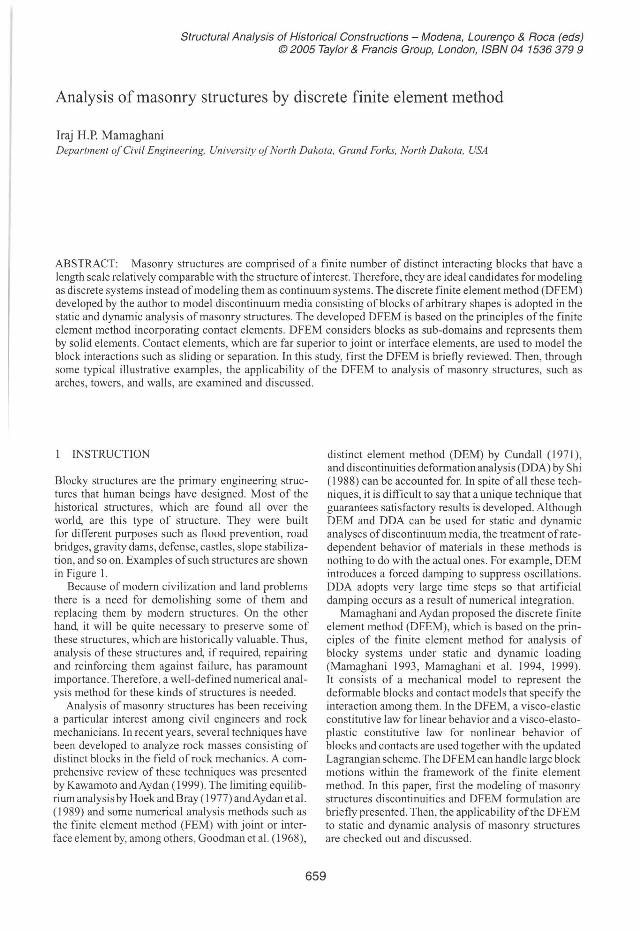
Figure 3. Modeling blocks contact.
where ç = (-2x' +x; +x;,,)/L, and L =x; -x;". Then, the relation between the strains and nodal displacemenls becomes:
(12)
Thus, the stiffness matrix of contact element in the (7) local coordinate system is explicitly obtained as:
(8)
F= J NTbdn + J jVTtdr (9) o. r.
3.2 Modeling of contacts
The contact element is used to model contacts ofblocks in masonry structure discontinuities. Let us consider a two-nodded element Im in two-dimensional space and lake two coordinate systems oxy and o' x'y' as shown in Figure 3. Assuming that, the slrain component By'y' is negligible; the remaining strain components take lhe following form:
ôu' 6 .. =-
xx ox" &v'
rx'y' = ôx' (lO)
LeI us assume that the shape functions are linear such lhat:
N, = 0.5(1 - n Nm = 0.5(1 +.;) (11)
661
[O
k:' k; K'=
-k:,
O
(13)
-k;, O] O -k;
O k;, O
O k;
O
-k: in which,
(14)
(15)
Here, Ac is the contact area; E" and Gs are normal and shear elastic moduli of disconlinuity, respectively. The stiffness matrix in lhe local coordinate syslem is then transformed to the stiffness matrix in the global coordinate system by the following relationship:
(16)
where,
[,",a sinO O
o~;". j -sinO cosO O T=
O O cosO
O O -sinO cosO
(17)
8=tan-,(Ym-Y, ) (18) Xm -x,
The viscosity (damping) matrix of contact element in local coordinate system can be also obtained in a similar manner as given below:
r~ O ,
C'= , c,\'
-cII
O
O -c.:.
(19)
(20)
, G· Ac c.~ = .1' ' -, --,
XIII -x, (21)
where E: and G; are normal and shear viscosity moduli of discontinuity, respectively. In the above equations, the values of coefficients in the stiffness and viscosity matrices, as well as the value of e, are affected by updating geometrical changes of blocks and contacts. It is worth noting that on the basis of simplification ofthe finite element modeling ofblock contacts, using the small strain theory for modeling of the large deformation, a small error is always present in the computed strains of contacts. Nevertheless, such an error is quite negligible as the geometry of the block system is incrementally updateel, which allows us to take into account the effect of higher order tenns in the definition of the finite strain tensor.
4 NUMERICAL RESULTS AND DISCUSSIONS
In the numerical study, when the inertia term is considereel, contacts and blocks are assumed to behave as an elasto-visco-plastic material or a visco-elastic material. On the other hanel, if the inertia term is omitted, then the behavior of contacts and blocks are assumed to be elasto-plastic or elastic. Application ofthe DFEM to the numerical analysis of rock slopes (Mamaghani and Aydan 2000, Aydan et aI. 1996) and stability ofa single block on an incline and some masonry structures was reported by the author and his co-workers (Mamaghani
1993, Mamaghani et aI. 1994, 1999, Tokashiki et aI. 2001). In this section, some typical numerical results for static and dynamic response ofmasonry structures obtained by the DFEM will be presented and discussed. In the analyses reported herein, tensile strength of the contact element was assumed to be zero. The Mohr-Coulomb yield criterion was implemented in the present codes. Nevertheless, one can easily implement any yield criterion, which is appropriate for the plastic or visco-plastic behavior. Contact areaAc was assumed to be a halfofthe area ofthe side ofa block to which the contact element is attached. The thickness ofthe bands was taken as twice the weighted asperity height. Taking into account the results reported by Aydan et aI. (1989), the thickness of the bands was selected as 10 mm. The secant stiffness method together with updated Lagrangian Scheme was employed to deal with nonlinear behavior. The constant strain triangular element with two degrees of freedoms at each node, formed by properly joining the corners and contact nodes of an individual block, was adopted for f inite element meshing ofthe blocks (Mamaghani 1993). However, it must be noted that the method is not restricted to the use of such elements and one can easily implement finite elements with any number of chosen nodes.
The analysis is a pseudo time stepping incrementai procedure. First, the initial configuration of the structural system, boundary conditions, and material properties are input. Then, iterations are carried out by forming the global stiffness matrix and solving the equilibrium equations of the system. Later, the strains and stresses of elements are computed. The no-tension condition and Mohr-Coulomb's yield criterion are checked and the excess forces at contacts are appl ied to the updated configuration as the penalty load in the subsequent iteration until the norm of excess force vector converges to a very small value of convergence tolerance. The computation is terminated when a stable configuration is achieved or the global stiffness matrix becomes ill-conditioned as single or multiple blocks tend to move without any interaction with each other corresponding to the failure of the system. The details of the numerical algorithm and computational procedure are given in the work by Mamaghani (1993).
4.1 Dynamic stability olone block on an incline
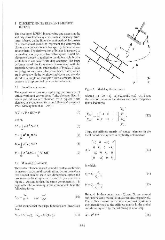
The dynamic stability of square and rectangular blocks on a plane with an inclination of 30° was analyzed by the DFEM. The rectangular block was assumed to have a height to breadth ratio h / b = 1/3. The assumed material properties ofthe intact rock blocks and mechanical properties of the contact elements used in numerical analyses are given in Table 1. In the table À, M, À *, and M * stand for the elastic and viscous Lame's constants, respectively. p denotes the unit weight of the blocks. En, Gs, E: , and G; stand for lhe elastic
662

Table I. Properties of intact rock and contacts.
Properties of blocks Properties of contacts
À J1- À' J1- ' y En (MPa) (MPa) (MPa s) (MPa . s) (kN j m3) (MPa)
10 10 5 5 25 0.1
Square Block Rectangular Block
Figure 4. Dynamic stability of a black on an incline.
and viscous normal and shear modulus of the contact, respectively. The friction angles for square and rectangular blocks are cp = 25° and cp = 35°, respectively. Figure 4 shows computed configurations ofthe square block of size 4 m x 4 m and a rectangular block of size 12 m x 4 m. The square block slides on the incline (time step /),/ = 0.04 sec) while the rectangular block topples (time step /),t = 0.0 I sec). These predictions are consistent with the kinematic conditions for the stability of a single block in the previous studies (Mamaghani 1993, Mamaghani et aI. 1999) as well as with the experimental results reported by Aydan et aI. (1989). It should, however, be noted that the discretisation of the domain, mechanical properties of blocks and contacts, and time steps may cause superficious oscillations and numerical instability.
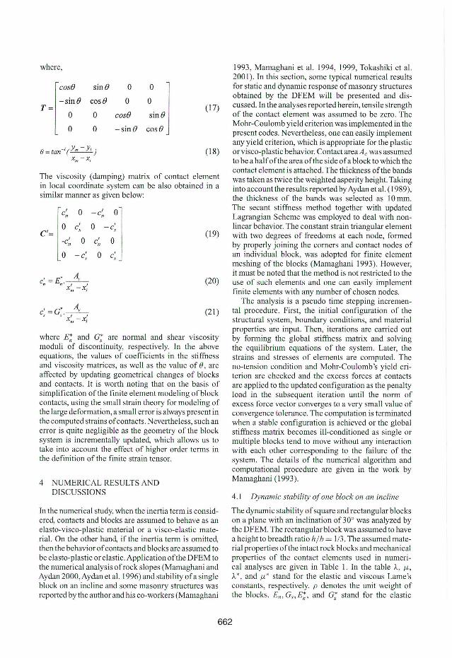
4.2 Ana/ysis of an arch struc/ure under s/atie /oading
Figure 5 shows an arch structure analyzed using the DFEM under static loading. In the numerical analysis, the assumed material properties of intact blocks are: Lame's constants À = 56 GPa and J1- = 21 G Pa, and unit weight p = 25 kN/m3 . The properties of contacts are assumed as: normal stiffness, EII = 50 GPa, and shear stiffness, Gs = 0.5 GPa. The friction angle between blocks is assumed as cp = 25° . The dimension of the blocks perpendicular to the xy plane is taken as w = 1.0 m, Figure 5. The arch is stable under its own weight. lt is still stable when the distributed uniform traction load per unit length over the arch is less than IA 7 kN/m. However, if the traction load reaches that levei, then the arch starts to be unstable. Figure 5 shows the configuration of the arch at failure, which takes place at iteration No. 27.
Gs E,: G* s c a, 'P (MPa) (MPa· s) (MPa· s) (MPa) (MPa) CO)
0.1 0.05 0.05 O O (25)35
I~ 0.50 m 1.23 m
lnitial configuration Failure configuration
Figure 5. Failure mode of a masonry arch.
4.3 Dynamic ana/ysis of areh struetures
This section is concerned with several applications of the DFEM to dynamic analysis of masonry arch structures. r n the analysis, the foundation of the structures was subjected to two types oflateral acceleration waves; Acc. No. I with a large period:
Aee = 0 .8te-OS' sin(t) x 981 (22)
and Acc. No. 2 with a small period:
Aee = 0.8te-Ol, sin(3t) x 981 (23)
in which t = time and Acc = lateral acceleration in gal, as shown in Figure 6.
The assumed accelerations are used to check the response of analyzed masonry structures by DFEM under two different waveforms. The material and mechanical properties ofblocks, foundations, and contacts are given in Table 2, where À and J1- denote Lame's constants, and p , En , G,., h and cp indicate unit weight of rock mass, elastic modulus, shear modulus, band width of contact elements, and friction angle, respectively. In all examples, the time step was chosen as 0.2 second.
Figures 7a, c and d show the initial and deformed configurations of a masonry arch at the time steps of23 (4.6 seconds) and 50 (lO seconds) subjected to the Acc. No. I and Acc. No. 2, respectively. For plotting the initial and deformed configurations, in this example and ali examples reported hereafter, the displacement in the deformed configurations is amplified
663

by 50 times to make more visible the mode of failure (deformed conf iguration) from the initial configuration. Figure 7c shows that the arch is slid at the base at the time step 23 under Acc. No. 1 and the crown blocks of the arch starts to fali apart while the side columns are still stable. Figure 7c shows that, under Acc. No. I at the time step 50, the arching action disappears and the crown blocks fali apart. The columns slide rei ative to the base and they tend to topple in two opposite directions. The blocks tend to separate within the side columns, see Figure 7c for the time step 50.
Figure 7d shows that, under Acc. No. 2 at the time step 23, there is no slide at the base ofthe arch while the crown blocks are separated and tend to fali apart. At the time step 23, the side columns ofthe arch exhibit relatively stable behavior under Acc. No. 2 as compared with the Acc. No. 1, Figures 7c and d. However, under Acc. No. 2 at the time step 50 (l O seconds), the side columns of the arch slide at the base and the arching action disappears while the blocks start to fali apart.
600 /',.1 ~ 0.2see
~ 400 ,!:!J Aee ~ 0.8/ e·o,S/sin I X 98 1
" o .",
200 1: " "il u
O u < 15
-200 Time (see)
-400
-600 (a) Aee. No.
600 /',.1 ~ 0.2see
Aee ~ 0.81 e·o,S/sin 31 X 98 1 -;;;
400 ,!:!J
" o .",
200 1: " "il u
O u < 15
-200
-400
-600 (b) Aee. No. 2
Figure 6. Lateral acceleration waves acting on foundation .
As expected, the toppling (failure) modes of the side columns of the arch differ depending on the nature of the imposed form of acceleration waves, as shown in Figures 7c and 7d fo r the time step 50.
Figure 7b shows the displacement responses with time of a nodal point at the top most-right corner ofthe arch corresponding to the Acc. No. I and Acc. No. 2. The results in Figure 7b indicates that, as expected, the displacement ofthe side column ofthe arch with time is much severe under the Acc. No. I as compared with the Acc. No. 2, especially in the early stage of loading. Figures 7c and 7d show that, under both of the imposed acceleration waves, the reaction of the toppled columns forces the crown block to move upward. This is beca use of the geometrically symmetric configuration of the structure and outward inclination of the crown block contact interfaces at the center of symmetry; Figure 7a. As can be realized by examining the displacement response curves in Figure 7b, the real value ofthe upward displacement is very small as compared with the dimension ofthe crown block. lt should
- Ace.No. 1 ------- Ace. No. 2
Scale(4m)
Number of lime SICp
(a) Initial configuration (b) Response at lhe (OP most-right comer
T ime slep 23 (4.6 scconds) Time slep 23 (4 .6 scconds)
Time step 50 ( 10 seconds) Time SICp 50 ( 10 seconds)
(c) Accelcration No. 1 (d) Acceleration No. 2
Figure 7. Initial and deformed configurations and displacement response with time of the arch.
Table 2. Material properties of rock blocks and contacts.
Properties of blocks Properties of contacts
À /L À* /L* P En Gs E~ G* s h rp (MPa) (MPa) (MPa · s) (MPa· s) (kN 1m3
) (MPa) (MPa) (MPa · s) (MPa· s) (mm) n 30 30 30 30 25 5.0 2.5 5.0 2.5 5 35
664

be noticed that in Figures 7c and d, the displacement is amplified using the illustration scale factor (50 times the actual scale) to make the failure mo de ofthe whole structure more visible.
(a) Initial configuration
Time step 22 Time step 50
(b) Acc. No. I
Time step 22 Time step 50 (c) Acc. No. 2
Initial configuration Failure configuration
Figure 8. lnitial and deformed configuration ofthe masonry tower.
3
~ -- Acc. No. 1 E. 2 ------ - Acc. No. 2
ii E " u
" ]- ,, - "
i5 " , .; ~----
,
O O 10 20 30 40 50
Number af time step
Figure 9. Displacement response with time at the top most-right comer of the tower.
4.4 Dynamic analysis ofmasonry towers
Figures 8a, 8b, and 8c show the initial and deformed configurations of a masonry tower at the time steps of 22 (4.4 seconds) and 50 (lO seconds) corresponding to the Acc. No. I and Acc. No. 2, respectively. Figure 8b shows that when the tower is subjected to Acc. No. I, there is a sliding at the base of the tower at time step 22 and the most upper blocks start to detach at the top of the tower. At time step 50, relative sliding and separation occurs along block contacts and the two most upper blocks tend to topple in two opposite directions. Figure 8c shows that, under Acc. No. 2, there is no sliding of the tower at the base while the most upper blocks ofthe tower are separated and tend to topple at time step 22. At time step 50, there is a relative slide at the base ofthe tower and blocks are slid and detached along block contacts. Figure 9 shows the displacement response versus the number of time step for a nodal point at the top most right comer ofthe tower (monitoring node) corresponding with both of the imposed acceleration waves. As shown in Figure 9, the toppling ofthe top most-right block ofthe tower is more severe under Acc. No. I as compared with the Acc. No. 2.
Comparison of the responses in Figures 8 and 9 also show that the failure mode of the tower depends on the nature of the imposed acceleration wave. The tower shows relatively stable behavior under Acc. No. 2 with a small period as compared with that ofthe Acc. No. I with a large period at the time step 22. However, the tower does not retum to its original position and ceases to be stable at the end of shaking under both of the imposed forms of the acceleration waves, see Figure 8 for time step 50. It is worth noting that, as shown in Figure 8, the response of the tower is quite similar to those may be expected in actual earthquakes.
Although the examples discussed above are very simple structures, they illustrate the fundamental features of the developed DFEM. It is also possible to consider and analyze more complicated masonry structures by the DFEM. Nevertheless, more experimental information is required on the constitutive parameters of blocks and contacts before conducting the analysis of such structures.
5 CONCLUSIONS
This paper was concemed with static and dynamic analysis of masonry structures which are comprised of a finite number of distinct, interacting blocks that have the length scale relatively comparable with the structure of interest, using the discrete finite element method (DFEM) recently developed by the author. The DFEM is based on the principIes ofthe finite element method incorporating contact elements. It considers blocks as sub-domains and represents them by solid elements. Contact elements are used to model the
665
block interactions such as sliding or separation. The DF EM ca1culates displacements at the joints as well as deformation within the blocks, which can be used to follow the processes ofthe failure mechanism ofs lopes under static as well as dynamic loading. Through some typical illustrative examples, the applicability of the DFEM to static and dynamic analysis of masonry structures were investigated and discussed. It has been shown that the DFEM is capable of simulating large displacement ofblocky systems. It was found that the DFEM is a promising method for studying behavior of masonry structures under static and dynamic loading. However, the hyperbolic scheme ofthe DF EM is still in its formative phase for which both experiments on viscous characteristics of blocks and contacts, as well as a numerically stable time-discretisation scheme, are felt to be necessary.
REFERENCES
Aydan, O., Mamaghani, I.H.P. & Kawamoto, T. 1996. Applications of discrete finite element method (DFEM) to rock engineering structures. NARMS'96, 2nd North American Rock Mechanics Symposium Tools and Techniques in Rock Mechanics, Canada, pp. 2039- 2046.
Aydan, O., Shimizu, Y. & 1chikawa, Y. 1989. The effective fa ilure modes and stability of slopes in rock mass with two discontinuity sets. Rock Mechanics and Rock Engineering, Vol. 22(3), pp. 163-188.
Cundall, P. A. 1971. A computer model for simulating progressive large-scale movements in blocky rock systems. Proc. Int. Symp. on Rock Fracture, lI-8 , Nancy, France.
Goodman, R.E., Taylor, R. & Brekke, T L. 1968. A model for the mechanics of jointed rock. J. of Soi! Mechs. and Found. Eng. Div. , ASCE, SM3, Vol. 94(3), pp. 637-659.
Hoek, E. & Bray, J.w. 1977. Rock slope engineering. The Institution of Mining and Metallurgy, Revised Second Edition, London.
Kawamoto, T & Aydan, O. 1999. A review ofnumerical analysis oftunnels in discontinuous rock masses. Int. J. Numer. Anal. Meth. Geomech., 23, pp. 1377- 1391.
Mamaghani, I.H.P. 1993. Numerical analysis for stability of a system of rock blocks. Master Thes is. Department of Civil Engineering, Nagoya University, Nagoya, Japan.
Mamaghani, LH. P. & Aydan, O. 2000. Stability analysis of slopes by discrete f inite element method. GeoEng 2000, November 19- 24, Melbourne, Australia .
Mamaghani, LH.P., Aydan, O. & Kajikawa, Y. 1999. Analysis of masonry structures under static and dynamic 10ading by discrete finite element method. Journal of Structural Mechanics and Earthquake Engineering. Japan Society ofCivi l Engineers, JSCE, No. 626/1-48, pp. 1- 12.
Mamaghan i, LH.P., Baba, S., Aydan, O. & Shimizu, Y. 1994. Discrete finite element method fo r blocky systems. Proc. ofthe Eighth Int. Conl on Computer Methods andAdvances in Geomechanics (IACMAG), Morgantown, USA, Vol. 1, pp. 843- 850.
Shi, G.H. 1988. Discontinuous deformation analysis: a new numerical model for the statics and dynamics ofblock system. PhD Thesis. Dept. of Civil Engineering, University of California, Berkeley.
Tokashiki, N., Aydan, O., Shimizu, Y. T , & Mamaghani, LH.P. 2001. A stability analysis of masonry walls by di screte finite element method (DFEM). Proc. of the 10th Int. Conf on Computer Methods andAdvances in Geomechanics (IACMAG'01), 7-12 January 200 1, Tucson, Arizona, USA.
666