Embed Size (px)
Citation preview
metals
Article
Analysis of Hole Quality and Chips Formation in the DryDrilling Process of Al7075-T6
Numan Habib 1, Aamer Sharif 1, Aqib Hussain 1, Muhammad Aamir 2,* , Khaled Giasin 3 ,Danil Yurievich Pimenov 4 and Umair Ali 1
�����������������
Citation: Habib, N.; Sharif, A.;
Hussain, A.; Aamir, M.; Giasin, K.;
Pimenov, D.Y.; Ali, U. Analysis of
Hole Quality and Chips Formation in
the Dry Drilling Process of Al7075-T6.
Metals 2021, 11, 891. https://doi.org/
10.3390/met11060891
Academic Editors: Wei Zhou and
Antonio Riveiro
Received: 7 May 2021
Accepted: 27 May 2021
Published: 29 May 2021
Publisher’s Note: MDPI stays neutral
with regard to jurisdictional claims in
published maps and institutional affil-
iations.
Copyright: © 2021 by the authors.
Licensee MDPI, Basel, Switzerland.
This article is an open access article
distributed under the terms and
conditions of the Creative Commons
Attribution (CC BY) license (https://
creativecommons.org/licenses/by/
4.0/).
1 Department of Mechanical Engineering, CECOS University of Information Technology and EmergingSciences, Peshawar 25000, Pakistan; [email protected] (N.H.); [email protected] (A.S.);[email protected] (A.H.); [email protected] (U.A.)
2 School of Engineering, Edith Cowan University, Joondalup, WA 6027, Australia3 School of Mechanical and Design Engineering, University of Portsmouth, Portsmouth PO1 3DJ, UK;
[email protected] Department of Automated Mechanical Engineering, South Ural State University, 454080 Chelyabinsk, Russia;
[email protected]* Correspondence: [email protected]
Abstract: Millions of holes are produced in many industries where efficient drilling is consideredthe key factor in their success. High-quality holes are possible with the proper selection of drillingprocess parameters, appropriate tools, and machine setup. This paper deals with the effects ofdrilling parameters such as spindle speed and feed rate on the chips analysis and the hole qualitylike surface roughness, hole size, circularity, and burr formation. Al7075-T6 alloy, commonly usedin the aerospace industry, was used for the drilling process, and the dry drilling experiments wereperformed using high-speed steel drill bits. Results have shown that surface roughness decreasedwith the increase in spindle speed and increased with the increase in the feed rate. The hole sizeincreased with the high spindle speed, whereas the impact of spindle speed on circularity errorwas found insignificant. Furthermore, short and segmented chips were achieved at a high feed rateand low spindle speed. The percentage contribution of each input parameter on the output drillingparameters was evaluated using analysis of variance (ANOVA).
Keywords: drilling; Al7075-T6; surface roughness; hole size; circularity; burrs; chips analysis
1. Introduction
Drilling is a manufacturing process that is extensively used in many industries suchas in the automotive and aerospace industries, where a considerable number of holes areneeded for assembly operation [1,2]. The common problems associated with the drillingprocess include the high surface finish, high circularity error, deviation of the holes fromthe nominal size, and burr formation around the hole edges [3–5]. Therefore, improperdrilling parameters, low hole quality, and rapid tool wear may lead to part rejection, whichincreases the total manufacturing cost and time [6,7].
Aluminium and its alloys have many applications in different manufacturing indus-tries due to their excellent mechanical properties [8,9]. Al7075-T6 is one of the aluminiumalloys used for manufacturing aircraft engines, fuselage, aircraft structure, aircraft skin,and internal supporting parts [10]. Various analytical and experimental approaches werepreviously applied to improve the drilling process on aluminium alloys. Table 1 showssome of the previous studies on aluminium alloys.
Metals 2021, 11, 891. https://doi.org/10.3390/met11060891 https://www.mdpi.com/journal/metals

Metals 2021, 11, 891 2 of 9
Table 1. Previous studies on drilling of aluminium alloys.
Alloy Type CuttingParameters Cutting Tool Output
Parameters Ref
Al7075
Vc = 22, 44, 66 (m/min)f = 0.15 (mm/min).
Condition = Dry andconventional cutting fluid
HSSD = 6 mmθ = 118◦
Ra, C, W [11]
Al7075Vc = 25 (m/min)f = 50 (mm/min)Condition = Dry
HSS-TiHSS-CoHSS-Mo
D = 7 mmθ = 123◦, 137◦, 114◦
ψ = 65◦
Ra, Fz [12]
Al7075n = 910, 1420, 2000 (rpm)
f = 0.06, 0.08, 0.10 (mm/rev)Condition = Dry
HSSD = 5 mm
θ = 118◦, 126◦, 135◦Ra, Z [13]
Al7075f = 0.05, 0.1, 0.15 (mm/rev)Vc = 60, 100, 140 (m/min)
Condition = Dry
Tungsten carbideD = 5 mm
θ = 120◦, 130◦, 140◦Ra [14]
Al7075f = 0.1, 0.2, 0.3 (mm/rev)
Vc = 4, 12, 20 (m/min)Condition = Dry
HSSD = 5 mm
θ = 90◦, 118◦, 135◦Ra, H [15]
Al6061n = 1000, 1500, 2000 (rpm)
f = 0.04, 0.08 (mm/rev)Condition = Dry
HSS-TIND = 8 mmθ = 118◦
Ra, Z, C, W [16]
Al5050 Vc = 15, 20, 25 (m/min)f = 0.1, 0.2, 0.3 (mm/rev)
HSSD = 6, 8, 10 mm Ra [17]
Surface roughness: Ra, diameter: D, circularity: C, hole size: Z, tool wear: W, feed rate: f, cutting speed: Vc, helixangle: ψ, point angle: θ, high-speed steel: HSS, thrust force: Fz, spindle speed: n, burr height: H.
For instance, Abd Halim et al. [11] studied the effects of the cutting condition andcutting parameters during the drilling of Al7075 alloy in terms of hole circularity, surfaceroughness, and tool wear. The results showed that the hole circularity, surface roughness,and tool wear are influenced mainly by cutting parameters. Ghasemi et al. [12] investigatedpre-center holes’ drilling strategy and tool material in drilling Al7075 on surface roughness,dimensional accuracy, and thrust force. The results showed that pre-center drill holes ondrilling Al7075 improved the hole quality and reduced the thrust force. Kao et al. [13]used the gray-Taguchi method in their study to investigate the machining parametersin the drilling of Al7075. It was concluded that the hole quality was superior in theinverted drilling methods compared to standard drilling. Yasar et al. [14] concluded thatthe surface roughness decreased with an increase in drill point angle, while the rise infeed rate increased the surface roughness during dry drilling of Al7075. Kilickap et al. [15]discovered that the combination of low feed rate, low cutting speed, and high point anglein drilling Al7075 was essential to minimize surface roughness and burr height in drillingAl7075. Apart from the studies on aluminium alloy Al7075, Uddin et al. [16] studiedthe drilling of Al6061 and concluded that the burr formation and roundness error weremainly affected by varying the feed rate. Haleel [17] worked on the optimization of processparameters using the Taguchi method for minimum surface roughness in the drillingprocess of Al5050. The results showed that tool diameter was the most significant factorthat affected the surface roughness following the feed rate and cutting speed.
The above studies indicate that most of the previous investigations were made eitheron other drilling parameters of Al7075-T6 or other alloys of aluminium. Furthermore, thereis still a lack of research regarding the hole quality in Al7075-T6 alloy and needs furtherinvestigation. A good hole quality with less dimensional deviation improves productivityand decreases manufacturing costs and time. Therefore, this study investigates the drilling
Metals 2021, 11, 891 3 of 9
of Al7075-T6 to comprehensively analyze the influence of process parameters, i.e., spindlespeed and feed rate, on the circularity error, surface roughness, hole diameter, and burrformation, which are the essential characteristics of hole quality. In addition, the generatedchips in the drilling process were analyzed. Furthermore, ANOVA (analysis of variance)was used to find the percentage contribution of each input parameter on the analyzedoutput parameters.
2. Materials and Methods
In the current study, a vertical milling machine (Model: Victoria-Elliott U2, London,UK) was used to conduct the drilling experiments. The spindle speeds used were 141, 308,and 548 (rpm), and the feed rates were 0.53, 1.35, and 1.94 (inch/min). The workpiecematerial was Al7075-T6 alloy with 110 mm × 60 mm and a thickness of 10 mm. Uncoatedhigh-speed steel (HSS) twist drills (Dormer Drills, UK) with a helix angle of 30◦ and apoint angle of 130◦ were used. All the drilling experiments were conducted under dryconditions due to environmental concerns [18]. Dry drilling also reduces the need to cleanthe aeronautical structures before installing rivets to obtain high-quality holes [19].
The hole size and circularity error were measured using a coordinate measuring ma-chine (CMM, Taichung, Taiwan). The surface roughness tester Mitutoyo (SJ-201, Kawasaki,Japan) was used to measure the surface roughness (Ra). Each hole was cleaned with high-pressure air to remove small debris from the hole wall for accurate measurement of Ra.Furthermore, the entry and exit burrs of holes were examined using a digital microscope.
3. Results and Discussions3.1. Surface Roughness, Hole Size, and Circularity
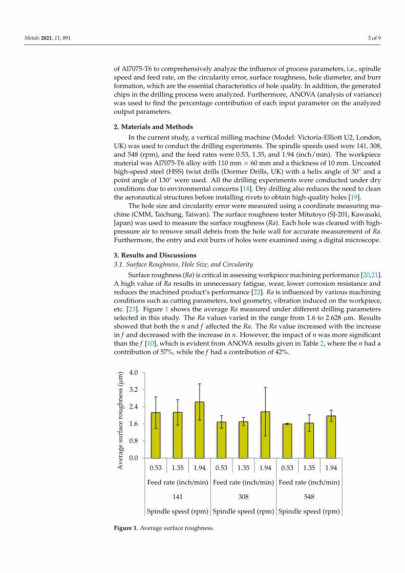
Surface roughness (Ra) is critical in assessing workpiece machining performance [20,21].A high value of Ra results in unnecessary fatigue, wear, lower corrosion resistance andreduces the machined product’s performance [22]. Ra is influenced by various machiningconditions such as cutting parameters, tool geometry, vibration induced on the workpiece,etc. [23]. Figure 1 shows the average Ra measured under different drilling parametersselected in this study. The Ra values varied in the range from 1.6 to 2.628 µm. Resultsshowed that both the n and f affected the Ra. The Ra value increased with the increasein f and decreased with the increase in n. However, the impact of n was more significantthan the f [10], which is evident from ANOVA results given in Table 2, where the n had acontribution of 57%, while the f had a contribution of 42%.
Metals 2021, 11, x FOR PEER REVIEW 4 of 9
Figure 1. Average surface roughness.
Figure 2 shows the deviation of holes from the nominal size (10 mm in this study). The results indicate that all holes were oversized. The variation in hole size in the current study is only in the range of 0.870–0.198 mm. Both the n and f have an impact on the hole size. However, the contribution of f on hole size was more, i.e., 82.02%, compared to the 15.99% contribution of n. Figure 2 also shows that an increase in n increased the deviation of hole size, while the rise in f reduced the deviation of hole size. According to Kurt et al. [22], the increase in n might result in vibration, chatter, and temperature, which signifi-cantly impact the accuracy of drilled holes.
Figure 3 depicts the circularity error under different drilling parameters selected in this study. In the current study, the circularity was influenced by both n and f. The increase in the f decreased circularity error, while the high n resulted in an increase in the circular-ity errors. The ANOVA results in Table 2 show that the influence of f on the circularity was more with a percentage contribution of 88.87%. The n indicated a p-value of greater than 0.05, which showed that n had an insignificant impact of only 2.28%. However, at high n, increasing the f from 1.35 to 1.95 inch/min, an increase in the circularity error was found. This rise in circularity error might be due to faster penetration of the cutting tool that increased the hole deflections and vibrations in the cutting tool [29].
0.0
0.8
1.6
2.4
3.2
4.0
0.53 1.35 1.94 0.53 1.35 1.94 0.53 1.35 1.94
Feed rate (inch/min) Feed rate (inch/min) Feed rate (inch/min)
141 308 548
Spindle speed (rpm) Spindle speed (rpm) Spindle speed (rpm)
Ave
rage
surf
ace
roug
hnes
s (µm
)
Figure 1. Average surface roughness.

Metals 2021, 11, 891 4 of 9
Table 2. ANOVA results.
SourceSurface Roughness Hole Size Circularity
p-Value Contribution p-Value Contribution p-Value Contribution
Model 0 99.19% 0.001 98.00% 0.022 91.15%Linear 0 99.19% 0.001 98.00% 0.022 91.15%
Spindle speed 0 57.01% 0.012 15.99% 0.632 2.28%Feed rate 0 42.18% 0.001 82.02% 0.008 88.87%
Error - 0.81% - 2.00% - 8.85%Total - 100.00% - 100.00% - 100.00%
The increase in the f increased the uncut chip thickness due to the rise in thrustforce [24,25], which deteriorated the hole quality, especially the Ra [26]. Additionally, thedecrease in the Ra due to the increase in n might be due to the built-up edge formation(BUE). Materials like aluminium with low ductility form BUE on the cutting tool. Therefore,low n in dry machining contribute to BUE formation [27]. Thus, the high n resulted in alesser amount of BUE, hence producing a better surface finish [28].
Figure 2 shows the deviation of holes from the nominal size (10 mm in this study). Theresults indicate that all holes were oversized. The variation in hole size in the current studyis only in the range of 0.870–0.198 mm. Both the n and f have an impact on the hole size.However, the contribution of f on hole size was more, i.e., 82.02%, compared to the 15.99%contribution of n. Figure 2 also shows that an increase in n increased the deviation of holesize, while the rise in f reduced the deviation of hole size. According to Kurt et al. [22], theincrease in n might result in vibration, chatter, and temperature, which significantly impactthe accuracy of drilled holes.
Metals 2021, 11, x FOR PEER REVIEW 5 of 9
Figure 2. Deviation of hole size.
Figure 3. Circularity error.
Table 2. ANOVA results.
Source Surface Roughness Hole Size Circularity p-Value Contribution p-Value Contribution p-Value Contribution
Model 0 99.19% 0.001 98.00% 0.022 91.15% Linear 0 99.19% 0.001 98.00% 0.022 91.15%
Spindle speed 0 57.01% 0.012 15.99% 0.632 2.28% Feed rate 0 42.18% 0.001 82.02% 0.008 88.87%
Error - 0.81% - 2.00% - 8.85% Total - 100.00% - 100.00% - 100.00%
3.2. Burr Formation Analysis The burr formation during the drilling process depends on various factors such as
the material properties of the workpiece, drilling parameters, and geometry of the drilled
10.000
10.060
10.120
10.180
10.240
0.53 1.35 1.94 0.53 1.35 1.94 0.53 1.35 1.94
Feed rate (inch/min) Feed rate (inch/min) Feed rate (inch/min)
141 308 548
Spindle speed (rpm) Spindle speed (rpm) Spindle speed (rpm)
Hol
e si
ze (m
m)
0.000
0.010
0.020
0.030
0.040
0.53 1.35 1.94 0.53 1.35 1.94 0.53 1.35 1.94
Feed rate (inch/min) Feed rate (inch/min) Feed rate (inch/min)
141 308 548
Spindle speed (rpm) Spindle speed (rpm) Spindle speed (rpm)
Cir
cula
rity
(mm
)
Figure 2. Deviation of hole size.
Figure 3 depicts the circularity error under different drilling parameters selected inthis study. In the current study, the circularity was influenced by both n and f. The increasein the f decreased circularity error, while the high n resulted in an increase in the circularityerrors. The ANOVA results in Table 2 show that the influence of f on the circularity wasmore with a percentage contribution of 88.87%. The n indicated a p-value of greater than0.05, which showed that n had an insignificant impact of only 2.28%. However, at high n,increasing the f from 1.35 to 1.95 inch/min, an increase in the circularity error was found.This rise in circularity error might be due to faster penetration of the cutting tool thatincreased the hole deflections and vibrations in the cutting tool [29].

Metals 2021, 11, 891 5 of 9
Metals 2021, 11, x FOR PEER REVIEW 5 of 9
Figure 2. Deviation of hole size.
Figure 3. Circularity error.
Table 2. ANOVA results.
Source Surface Roughness Hole Size Circularity p-Value Contribution p-Value Contribution p-Value Contribution
Model 0 99.19% 0.001 98.00% 0.022 91.15% Linear 0 99.19% 0.001 98.00% 0.022 91.15%
Spindle speed 0 57.01% 0.012 15.99% 0.632 2.28% Feed rate 0 42.18% 0.001 82.02% 0.008 88.87%
Error - 0.81% - 2.00% - 8.85% Total - 100.00% - 100.00% - 100.00%
3.2. Burr Formation Analysis The burr formation during the drilling process depends on various factors such as
the material properties of the workpiece, drilling parameters, and geometry of the drilled
10.000
10.060
10.120
10.180
10.240
0.53 1.35 1.94 0.53 1.35 1.94 0.53 1.35 1.94
Feed rate (inch/min) Feed rate (inch/min) Feed rate (inch/min)
141 308 548
Spindle speed (rpm) Spindle speed (rpm) Spindle speed (rpm)
Hol
e si
ze (m
m)
0.000
0.010
0.020
0.030
0.040
0.53 1.35 1.94 0.53 1.35 1.94 0.53 1.35 1.94
Feed rate (inch/min) Feed rate (inch/min) Feed rate (inch/min)
141 308 548
Spindle speed (rpm) Spindle speed (rpm) Spindle speed (rpm)
Cir
cula
rity
(mm
)
Figure 3. Circularity error.
3.2. Burr Formation Analysis
The burr formation during the drilling process depends on various factors such asthe material properties of the workpiece, drilling parameters, and geometry of the drilledtools [30]. Burr formation causes dimensional inaccuracies and the need for de-burring,which consumes about 30% of the total cost of the final product [30]. Additionally, de-burring is carried out manually, which reduces productivity [10]. Yazman et al. [31]explained three types of burr formation during types of burrs during the drilling processunder different drilling parameters, i.e., crown, transient, and uniform burrs. Crown burrsat the exit hole are large, irregular in shape, bend outwards, and considered the worstamong all the burr types that need more attention.
Figure 4 shows the microscopic and visual inspection of the burrs, which revealed thatthe f was the most influential parameter in burr formation compared to n. The effect of n onburr formation was also observed; however, only at a high f. According to Costa et al. [30],the high f increased the cutting forces, which result in high burr formation. Additionally,small thickness chips are formed with a low f, allowing jerk-free and stable drilling, whichresulted in less deviation from nominal size [16].
Metals 2021, 11, x FOR PEER REVIEW 6 of 9
tools [30]. Burr formation causes dimensional inaccuracies and the need for de-burring, which consumes about 30% of the total cost of the final product [30]. Additionally, de-burring is carried out manually, which reduces productivity [10]. Yazman et al. [31] ex-plained three types of burr formation during types of burrs during the drilling process under different drilling parameters, i.e., crown, transient, and uniform burrs. Crown burrs at the exit hole are large, irregular in shape, bend outwards, and considered the worst among all the burr types that need more attention.
Figure 4 shows the microscopic and visual inspection of the burrs, which revealed that the f was the most influential parameter in burr formation compared to n. The effect of n on burr formation was also observed; however, only at a high f. According to Costa et al. [30], the high f increased the cutting forces, which result in high burr formation. Additionally, small thickness chips are formed with a low f, allowing jerk-free and stable drilling, which resulted in less deviation from nominal size [16].
Figure 4 also shows the burrs at the exit were more prominent than the burrs at the entry side of the hole. This is because as the drill bit approaches the hole exit at higher spindle speed, the temperature rise increases the material’s ductility in the cutting area and results in more significant amounts of plastic deformation around the edges of the hole [32].
Figure 4. Burr formation.
3.3. Chip Analysis During the drilling operation of aluminium alloys, usually small and segmented
chips are desirable for the high-quality hole and increased tool life [33]. Liu et al. [34] have reported that fragmented and small chips prevent the tool from breaking. Additionally, the smoothness of the drilling process in aluminium alloys can be observed through the chip’s size, such as chip thickness and length [35]. Long continuous chips easily tangle around the drilling tool and need manual removal, which might interrupt the production [36]. Figure 5 depicts the chips produced during the drilling process of Al7075-T6 alloy, which shows that the length of chips was affected by both n and f. Sun and Guo [37] in-vestigated that longer chips were produced at high n due to high temperature that causes ductility in the material. Moreover, segmented chips were produced when the f increased, and n was decreased. However, the thickness of chips directly relates to the f and is in-versely associated with n. The f was more influential because the cross-sectional area in-creased at a high f, increasing the chip’s stiffness and making the chip prone to breaking easily [34].
According to the ISO-based chip classification chart, various chips are formed during the machining operation, including ribbon chips, helical chips, tubular chips, spiral chips,
Figure 4. Burr formation.

Metals 2021, 11, 891 6 of 9
Figure 4 also shows the burrs at the exit were more prominent than the burrs at theentry side of the hole. This is because as the drill bit approaches the hole exit at higherspindle speed, the temperature rise increases the material’s ductility in the cutting areaand results in more significant amounts of plastic deformation around the edges of thehole [32].
3.3. Chip Analysis
During the drilling operation of aluminium alloys, usually small and segmented chipsare desirable for the high-quality hole and increased tool life [33]. Liu et al. [34] havereported that fragmented and small chips prevent the tool from breaking. Additionally, thesmoothness of the drilling process in aluminium alloys can be observed through the chip’ssize, such as chip thickness and length [35]. Long continuous chips easily tangle aroundthe drilling tool and need manual removal, which might interrupt the production [36].Figure 5 depicts the chips produced during the drilling process of Al7075-T6 alloy, whichshows that the length of chips was affected by both n and f. Sun and Guo [37] investigatedthat longer chips were produced at high n due to high temperature that causes ductilityin the material. Moreover, segmented chips were produced when the f increased, and nwas decreased. However, the thickness of chips directly relates to the f and is inverselyassociated with n. The f was more influential because the cross-sectional area increased ata high f, increasing the chip’s stiffness and making the chip prone to breaking easily [34].
Metals 2021, 11, x FOR PEER REVIEW 7 of 9
corkscrew chips, arc chips, and needle and elemental chips [38]. Some types of chips are further classified as short, long, and snarled chips. In the current study, long-helical chips were achieved at 141 rpm. However, when the f increases from 0.53 inch/min to 1.35 inch/min, the long–helical chips converted into short-helical chips. Further increasing the f to 1.94 inches/min, chips were converted to the combination of short-helical and snarled chips. For 308 and 548 rpm, long-helical chips are formed at 0.53 inches/min. Furthermore, short–helical chips and a combination of short-helical and snarled chips are formed at f of 1.35 and 1.94 inch/min at 548 rpm, respectively.
Figure 5. Chip formation at various drilling parameters.
4. Conclusions In the current study, the evaluation of hole quality in the drilling of Al7075-T6 was
investigated. The conclusions drawn from experiments are as follows: The surface roughness in the drilling of Al7075-T6 decreased with the increase in the
spindle speed, while the rise in feed rate resulted in high values of surface roughness. The contributions of spindle speed and feed rate on the surface roughness were 57.01% and 42.18%, respectively. In the case of hole size, the high spindle speed increased the hole size, while the rise in feed rate reduced the deviation of holes from the nominal size, ex-cept at high spindle speed, where increasing the feed rate from 1.35 to 1.95 inch/min in-creased the deviation of hole size. From ANOVA, the percentage contributions of spindle speed and feed rate were 15.99% and 82.92%, respectively. Similarly, the circularity de-creased with a rise in feed rate with a percentage contribution of 88.87% compared to the insignificant impact of spindle speed with only 2.28% contribution. The feed rate was also the most influential parameter in burr formation compared to spindle speed. The burrs were mostly observed at a high feed rate. Furthermore, the entry burrs were found to be smaller than those formed at the exit of the hole. The short, segmented, and discontinuous chips were produced with an increase in the feed rate and decreased spindle speed.
Figure 5. Chip formation at various drilling parameters.
According to the ISO-based chip classification chart, various chips are formed duringthe machining operation, including ribbon chips, helical chips, tubular chips, spiral chips,corkscrew chips, arc chips, and needle and elemental chips [38]. Some types of chipsare further classified as short, long, and snarled chips. In the current study, long-helicalchips were achieved at 141 rpm. However, when the f increases from 0.53 inch/min to1.35 inch/min, the long–helical chips converted into short-helical chips. Further increasingthe f to 1.94 inches/min, chips were converted to the combination of short-helical and

Metals 2021, 11, 891 7 of 9
snarled chips. For 308 and 548 rpm, long-helical chips are formed at 0.53 inches/min.Furthermore, short–helical chips and a combination of short-helical and snarled chips areformed at f of 1.35 and 1.94 inch/min at 548 rpm, respectively.
4. Conclusions
In the current study, the evaluation of hole quality in the drilling of Al7075-T6 wasinvestigated. The conclusions drawn from experiments are as follows:
The surface roughness in the drilling of Al7075-T6 decreased with the increase in thespindle speed, while the rise in feed rate resulted in high values of surface roughness. Thecontributions of spindle speed and feed rate on the surface roughness were 57.01% and42.18%, respectively. In the case of hole size, the high spindle speed increased the hole size,while the rise in feed rate reduced the deviation of holes from the nominal size, except athigh spindle speed, where increasing the feed rate from 1.35 to 1.95 inch/min increased thedeviation of hole size. From ANOVA, the percentage contributions of spindle speed andfeed rate were 15.99% and 82.92%, respectively. Similarly, the circularity decreased witha rise in feed rate with a percentage contribution of 88.87% compared to the insignificantimpact of spindle speed with only 2.28% contribution. The feed rate was also the mostinfluential parameter in burr formation compared to spindle speed. The burrs were mostlyobserved at a high feed rate. Furthermore, the entry burrs were found to be smaller thanthose formed at the exit of the hole. The short, segmented, and discontinuous chips wereproduced with an increase in the feed rate and decreased spindle speed.
Further study could be considered at high cutting parameters using different drill bitmaterials and finite element modelling to investigate how these factors would affect thequality of the hole.
Author Contributions: Conceptualization, M.A., N.H.; methodology, N.H., A.S., A.H. and U.A.,validation, M.A., K.G. and D.Y.P., investigation, N.H., A.S., A.H. and U.A.; writing—original draftpreparation, N.H., A.S. and A.H., writing—review and editing, K.G. and D.Y.P. All authors have readand agreed to the published version of the manuscript.
Funding: This research received no external funding.
Institutional Review Board Statement: Not applicable.
Informed Consent Statement: Not applicable.
Data Availability Statement: The data presented in this study are available on request.
Acknowledgments: The authors are highly grateful for the support and facilitation at manufacturinglab at CECOS University and Peshawar Light Engineering Centre at CECOS Industrial Liaison Centre,Industrial Estate, Peshawar, Pakistan.
Conflicts of Interest: The authors declare no conflict of interest.
References1. Aamir, M.; Tolouei-Rad, M.; Giasin, K.; Nosrati, A. Recent advances in drilling of carbon fiber–reinforced polymers for aerospace
applications: A review. Int. J. Adv. Manuf. Technol. 2019, 105, 2289–2308. [CrossRef]2. Aamir, M.; Giasin, K.; Tolouei-Rad, M.; Ud Din, I.; Hanif, M.I.; Kuklu, U.; Pimenov, D.Y.; Ikhlaq, M. Effect of Cutting Parameters
and Tool Geometry on the Performance Analysis of One-Shot Drilling Process of AA2024-T3. Metals 2021, 11, 854. [CrossRef]3. Aamir, M.; Tolouei-Rad, M.; Vafadar, A.; Raja, M.N.A.; Giasin, K. Performance Analysis of Multi-Spindle Drilling of Al2024 with
TiN and TiCN Coated Drills Using Experimental and Artificial Neural Networks Technique. Appl. Sci. 2020, 10, 8633. [CrossRef]4. Aamir, M.; Tolouei-Rad, M.; Giasin, K. Multi-spindle drilling of Al2024 alloy and the effect of TiAlN and TiSiN-coated carbide
drills for productivity improvement. Int. J. Adv. Manuf. Technol. 2021, 1–10. [CrossRef]5. Koklu, U.; Morkavuk, S.; Featherston, C.; Haddad, M.; Sanders, D.; Aamir, M.; Pimenov, D.Y.; Giasin, K. The effect of cryogenic
machining of S2 glass fibre composite on the hole form and dimensional tolerances. Int. J. Adv. Manuf. Technol. 2021. [CrossRef]6. Aamir, M.; Tolouei-Rad, M.; Giasin, K.; Vafadar, A. Feasibility of tool configuration and the effect of tool material, and tool
geometry in multi-hole simultaneous drilling of Al2024. Int. J. Adv. Manuf. Technol. 2020, 111, 861–879. [CrossRef]7. Tolouei-Rad, M.; Aamir, M. Analysis of the Performance of Drilling Operations for Improving Productivity. In Drilling; Tolouei-
Rad, M., Ed.; IntechOpen: London, UK, 2021. Available online: https://www.intechopen.com/online-first/analysis-of-the-performance-of-drilling-operations-for-improving-productivity (accessed on 8 April 2021).

Metals 2021, 11, 891 8 of 9
8. Al-Tameemi, H.A.; Al-Dulaimi, T.; Awe, M.O.; Sharma, S.; Pimenov, D.Y.; Koklu, U.; Giasin, K. Evaluation of Cutting-Tool Coatingon the Surface Roughness and Hole Dimensional Tolerances during Drilling of Al6061-T651 Alloy. Materials 2021, 14, 1783.[CrossRef]
9. Aamir, M.; Tolouei-Rad, M.; Giasin, K.; Vafadar, A. Machinability of Al2024, Al6061, and Al5083 alloys using multi-holesimultaneous drilling approach. J. Mater. Res. Technol. 2020, 9, 10991–11002. [CrossRef]
10. Aamir, M.; Giasin, K.; Tolouei-Rad, M.; Vafadar, A. A review: Drilling performance and hole quality of aluminium alloys foraerospace applications. J. Mater. Res. Technol. 2020, 9, 12484–12500. [CrossRef]
11. Abd Halim, N.F.H.; Dahnel, A.N.; Ismail, A.A.; Zainudin, N.A. An Experimental Investigation on Drilling of Aluminum Alloy(Al 7075) using High Speed Steel Cutting Tools. Test Eng. Manag. 2020, 83, 1451–1456.
12. Ghasemi, A.H.; Khorasani, A.M.; Gibson, I. Investigation on the effect of a pre-center drill hole and tool material on thrust force,surface roughness, and cylindricity in the drilling of Al7075. Materials 2018, 11, 140. [CrossRef]
13. Kao, J.-Y.; Hsu, C.-Y.; Tsao, C.-C. Experimental study of inverted drilling Al-7075 alloy. Int. J. Adv. Manuf. Technol. 2019, 102,3519–3529. [CrossRef]
14. Yasar, N.; Boy, M.; Günay, M. The effect of drilling parameters for surface roughness in drilling of AA7075 alloy. In Proceedingsof the MATEC Web of Conferences, Iasi, Romania, 3 July 2017; p. 01018.
15. Kilickap, E. Modeling and optimization of burr height in drilling of Al-7075 using Taguchi method and response surfacemethodology. Int. J. Adv. Manuf. Technol. 2010, 49, 911–923. [CrossRef]
16. Uddin, M.; Basak, A.; Pramanik, A.; Singh, S.; Krolczyk, G.M.; Prakash, C. Evaluating hole quality in drilling of Al 6061 alloys.Materials 2018, 11, 2443. [CrossRef]
17. Haleel, A.J. Optimization Drilling Parameters of Aluminum Alloy Based on Taguchi Method. Al-Khwarizmi Eng. J. 2018, 14, 14–21.[CrossRef]
18. Sarikaya, M.; Gupta, M.K.; Tomaz, I.; Danish, M.; Mia, M.; Rubaiee, S.; Jamil, M.; Pimenov, D.Y.; Khanna, N. Cooling techniques toimprove the machinability and sustainability of light-weight alloys: A state-of-the-art review. J. Manuf. Process. 2021, 62, 179–201.[CrossRef]
19. Klocke, F.; Eisenblätter, G. Dry cutting. CIRP Ann. 1997, 46, 519–526. [CrossRef]20. Aamir, M.; Tu, S.; Giasin, K.; Tolouei-Rad, M. Multi-hole simultaneous drilling of aluminium alloy: A preliminary study and
evaluation against one-shot drilling process. J. Mater. Res. Technol. 2020, 9, 3994–4006. [CrossRef]21. Aamir, M.; Tu, S.; Tolouei-Rad, M.; Giasin, K.; Vafadar, A. Optimization and modeling of process parameters in multi-hole
simultaneous drilling using taguchi method and fuzzy logic approach. Materials 2020, 13, 680. [CrossRef] [PubMed]22. Kurt, M.; Kaynak, Y.; Bagci, E. Evaluation of drilled hole quality in Al 2024 alloy. Int. J. Adv. Manuf. Technol. 2008, 37, 1051–1060.
[CrossRef]23. Giasin, K.; Ayvar-Soberanis, S.; Hodzic, A. An experimental study on drilling of unidirectional GLARE fibre metal laminates.
Compos. Struct. 2015, 133, 794–808. [CrossRef]24. Hanif, M.I.; Aamir, M.; Ahmed, N.; Maqsood, S.; Muhammad, R.; Akhtar, R.; Hussain, I. Optimization of facing process by
indigenously developed force dynamometer. Int. J. Adv. Manuf. Technol. 2019, 100, 1893–1905. [CrossRef]25. Hanif, M.I.; Aamir, M.; Muhammad, R.; Ahmed, N.; Maqsood, S. Design and development of low cost compact force dynamometer
for cutting forces measurements and process parameters optimization in turning applications. Int. J. Innov. Sci. 2015, 3, 306–3016.26. Kaplan, Y.; Okay, S.; Motorcu, A.R.; Nalbant, M. Investigation of the effects of machining parameters on the thrust force and
cutting torque in the drilling of AISI D2 and AISI D3 cold work tool steels. Indian J. Eng. Mater. Sci. 2014, 21, 128–138.27. Ratnam, M. 1.1 factors affecting surface roughness in finish turning. Compr. Mater. Finish. 2017, 1, 1–25.28. Cassier, Z.; Prato, Y.; Muñoz-Escalona, P. Built-up edge effect on tool wear when turning steels at low cutting speed. J. Mater. Eng.
Perform. 2004, 13, 542–547. [CrossRef]29. Giasin, K.; Ayvar-Soberanis, S. An Investigation of burrs, chip formation, hole size, circularity and delamination during drilling
operation of GLARE using ANOVA. Compos. Struct. 2017, 159, 745–760. [CrossRef]30. Costa, E.S.; da Silva, M.B.; Machado, A.R. Burr produced on the drilling process as a function of tool wear and lubricant-coolant
conditions. J. Braz. Soc. Mech. Sci. Eng. 2009, 31, 57–63. [CrossRef]31. Yazman, S.; Köklü, U.; Urtekin, L.; Morkavuk, S.; Gemi, L. Experimental study on the effects of cold chamber die casting
parameters on high-speed drilling machinability of casted AZ91 alloy. J. Manuf. Process. 2020, 57, 136–152. [CrossRef]32. Shanmughasundaram, P.; Subramanian, R. Study of parametric optimization of burr formation in step drilling of eutectic Al–Si
alloy–Gr composites. J. Mater. Res. Technol. 2014, 3, 150–157. [CrossRef]33. Zhang, P.; Churi, N.; Pei, Z.J.; Treadwell, C. Mechanical drilling processes for titanium alloys: A literature review. Mach. Sci.
Technol. 2008, 12, 417–444. [CrossRef]34. Liu, K.; Li, J.; Sun, J.; Zhu, Z.; Meng, H. Investigation on chip morphology and properties in drilling aluminum and titanium
stack with double cone drill. Int. J. Adv. Manuf. Technol. 2018, 94, 1947–1956. [CrossRef]35. SenthilKumar, M.; Prabukarthi, A.; Krishnaraj, V. Study on tool wear and chip formation during drilling carbon fiber reinforced
polymer (CFRP)/titanium alloy (Ti6Al4 V) stacks. Procedia Eng. 2013, 64, 582–592. [CrossRef]36. Yazman, S.; Gemı, L.; Uludag, M.; Akdemır, A.; Uyaner, M.; Dispinar, D. Correlation between Machinability and Chip Morphology
of Austempered Ductile Iron. J. Test. Eval. 2017, 46, 1012–1021. [CrossRef]

Metals 2021, 11, 891 9 of 9
37. Sun, J.; Guo, Y. A new multi-view approach to characterize 3D chip morphology and properties in end milling titanium Ti–6Al–4V.Int. J. Mach. Tools Manuf. 2008, 48, 1486–1494. [CrossRef]
38. Jawahir, I.S. Chip-forms, Chip Breakability and Chip Control. In CIRP Encyclopedia of Production Engineering; Laperrière, L.,Reinhart, G., Eds.; Springer: Berlin/Heidelberg, Germany, 2014; pp. 178–194.


![| Home []au gen etau dos. 901i BRACES TECAÑiCAL chips. Elastique. - LOngeur ONE SIZE 9011-84-9900 . JOBIVIAN 5586 DRY-TECH BAMBOO POLO TECHNICAL Dry tech en polyester pour une meilleure](https://img.pdfslide.us/doc/110x75/603aa623e34a1f7d9c31eb6d/-home-au-gen-etau-dos-901i-braces-tecaical-chips-elastique-longeur-one.jpg)