Embed Size (px)
Citation preview
8/13/2019 Analysis of Grain Structure in Forging
http://slidepdf.com/reader/full/analysis-of-grain-structure-in-forging 1/55
1
ANALYSIS OF GRAIN STRUCTURE IN FORGING
A study and analysis carried out at Engineering Shops and Foundry (ES&F)
Vishakhapatnam Steel Plant
Mini Project Work
Under estimated guidance of
SRI S. MANDAL
AGM (ES&F)
Vishakhapatnam Steel Plant
DEPARTMENT OF PRODUCTION ENGINEERING
NATIONAL INSTITUTE OF TECHNOLOGY, AGARTALA
8/13/2019 Analysis of Grain Structure in Forging
http://slidepdf.com/reader/full/analysis-of-grain-structure-in-forging 2/55
2
DECLARATION
We hereby declare that the Project Work entitled the “Analysis of grain structure in
forging”, (A study and analysis carried out at Forging shop/ES&F, Vishakhapatnam Steel
Plant) is an original work done by us and not submitted earlier for the award of our
degree and diploma or any other universities similar to this.
Group member
PRASENJIT BISWAS 10UPE018
SRIJIT BISWAS 10UPE027
DIPANJAN DAS 10UPE006
PLACE: - VISAKHAPATNAM STEEL PLANT
DATE –
8/13/2019 Analysis of Grain Structure in Forging
http://slidepdf.com/reader/full/analysis-of-grain-structure-in-forging 3/55
3
CERTIFICATE
This is to certify that “
PRASENJIT BISWAS, SRIJIT BISWAS, DIPANJAN
DAS” has satisfactorily completed the project work entitled ““ANALYSIS OF GRAIN
STRUCTURE IN FORGING”” (A study and analysis carried out at Forging shop /
ES&F, Vishakhapatnam steel Plant).In partial fulfillment of the requirement for the
degree of Bachelor of Technology in Production Engg. during the academic year 2010-
2014.
MR. SUBRATA. MANDAL
AGM, (ES&F)
(Project Guide)
PLACE: VISAKHAPATNAM STEEL PLANT
DATE :
8/13/2019 Analysis of Grain Structure in Forging
http://slidepdf.com/reader/full/analysis-of-grain-structure-in-forging 4/55
4
BIO-DATA OF GUIDE
NAME : S. MANDAL
Designation : Asst. General Manager (Mech)
Engineering Shop & Foundry, Vishakhapatnam Steel Plant
Vishakhapatnam
Qualification: 1. B.E (Hoers) M.E, Utkal University
2. M.B.A (Finance), IGNOU
3. DCA, Academy of computer education
4. M.Tech (M.E Design) BITS, MESRA
5. Gold Medal Award in HIMER International Conference
6. Member in institute of Engg, India
7. Project Grade: 51 UG project work
03 PG project work
Address : 219-C, sector 3, Ukkunagaram, Vishakhapatnam-533032
Andhra Pradesh.
8/13/2019 Analysis of Grain Structure in Forging
http://slidepdf.com/reader/full/analysis-of-grain-structure-in-forging 5/55
5
ACKNOWLEDGEMENT
We hereby express our profound sense of gratitude to our guide Mr.Subrata
Mandal , [AGM (Mechanical) of Engineering shops and Foundry (ES&F),
Visakhapatnam Steel Plant, Visakhapatnam], for providing the necessary information andtaking great pain to help us complete this project. He has been kind enough to guide us
throughout this project by shedding light on our weaknesses and has enhanced our
strengths.
We also want to thank Mr.Sanjib Kr. Das [(DGM (Mechanical) RMHP
(works)] for lending us his help to the complete this project. He has been very much kind
and provided us his self-less support in our long run.
We also want to thank Visakhapatnam Steel Plant Authority for which wehave been able to do our training out here in VSP.
We also want to thank Mr. Anirban Bhattacharjee (Training and Placement
officer, National Institute of Technology, Agartala) for whom we have been able to come
here in Visakhapatnam Steel Plant and explored as much as we can.
We also want to thank all the guides of VSP for lending their support towards
us for which we were able to learn to our best.
We also want to thank all our friends and seniors who helped us to come this
way throughout.
8/13/2019 Analysis of Grain Structure in Forging
http://slidepdf.com/reader/full/analysis-of-grain-structure-in-forging 6/55
6
CONTENTS
Topic Page no
Synops i s 1
Int roduc t ion t o t he pro j ec t work 3
Visakhapat nam s t ee l P lant - Overv iew 4
Int roduc t ion t o met a l manuf ac t ur ing
proces se s and advant age and d i sadvant age
of var ious met a l manuf ac t ur ing proces se s
16
Int roduc t ion t o Forg ing 25
Ford ing equ ipment s and f urnaces 30
Import ance o f f org ing t emperat ure 37
Recrys t a l l i za t ion and Gra in growt h- an
int roduc t ion
40
Mechanica l met a l lurgy in f org ing 43
Analys i s o f Gra in s t ruc t ure in f org ing 46
Dat a ana lys i s 47
Conc lus ion 48
Bib l iography 49
8/13/2019 Analysis of Grain Structure in Forging
http://slidepdf.com/reader/full/analysis-of-grain-structure-in-forging 7/55
7
SYNOPSIS
The project deals with the analysis of grain structure in forging process. This project lays emphasis on the importance of changing the grain structure and itsimportance to improve the mechanical properties of the material used in forging purpose.
Forging can produce a piece that is stronger than an equivalent cast or machined part. As the metal is shaped during the forging process, its internal grain deforms tofollow the general shape of the part. As a result, the grain is continuous throughout the
part, giving rise to a piece with improved strength characteristics. Some metals may beforged cold, but iron and steel are almost always hot forged. Hot forging prevents thework hardening that would result from cold forging, which would increase the difficultyof performing secondary machining operations on the piece. Also, while work hardeningmay be desirable in some circumstances, other methods of hardening the piece, such asheat treating, are generally more economical and more controllable. Alloys that areamenable to precipitation hardening, such as most aluminium alloys and titanium, can be
hot forged, followed by hardening. Production forging involves significant capitalexpenditure for machinery, tooling, facilities and personnel. In the case of hot forging, ahigh-temperature furnace (sometimes referred to as the forge) is required to heat ingots or
billets. Owing to the massiveness of large forging hammers and presses and the parts theycan produce, as well as the dangers inherent in working with hot metal, a special buildingis frequently required to house the operation. In the case of drop forging operations,
provisions must be made to absorb the shock and vibration generated by the hammer.Most forging operations use metal-forming dies, which must be precisely machined andcarefully heat-treated to correctly shape the workpiece, as well as to withstand thetremendous forces involved.
So grain structure takes a major role in forging. Or other words in forging all theadvantage we got due to proper grain formation. So we have to give a wide importance ongrain study. So it is a very importance to know about grain formation.
This is a well-known phenomena that the forging process deform the materialin desired shape and improve the mechanical properties of a material, so by applyinga suitable temperatures and by impact or gradually increasing force with the help ofhammer and die to the material to increase its strength and reduce the ductility.
The reason for pursuing this project is the study of grain structure of the materialhas wide application in industries and has been used from early stages of manufacturing;
also it is a work of precise engineering because of its controlled range of heating andapplied force conditions.
The planning to undertake this project is to get in-depth knowledge of grainstructure in forging process and its requirement for industrial purpose, also we see thedifferent types of forging processes and so as to understand the changes in grain structurein a proper forging process, simultaneously consideration of the material composition ofthe material also plays an important role in selection of forging temperature.
Though forging is not a new area, it has not been put into effective use in the factthat most of the researchers look at the process in general so the main idea behind the
project is to analyze the existing grain structure, so as to understand the micro structural
level of change that takes place due to forging process.

8/13/2019 Analysis of Grain Structure in Forging
http://slidepdf.com/reader/full/analysis-of-grain-structure-in-forging 8/55
8
After the analyzing the different forging processes, we can understand which properties and to what extend those properties are imparting in the material. Further wecan understand the grain structure that is been given in forging process and co relate itwith the iron carbon equilibrium diagram.
At the final stage we conclude that to which extent temperature enhance the grainstructures of a material and how it is changing at the required properties of forging processes.
This is the main thing because of which we are doing this project so that we canknow what would happen when the grain size or grain structure rearrange itself.
8/13/2019 Analysis of Grain Structure in Forging
http://slidepdf.com/reader/full/analysis-of-grain-structure-in-forging 9/55
9
INTRODUCTION TO THE PROJECT WORK
The project entitled “THE ANALYSIS OF GRAIN STRUCTURE IN
FORGING”. Which explores information about grain structure, grain boundary and grain
formation in forging.
Forging is the process by which metal is heated and is shaped by plasticdeformation by suitably applying compressive force. Usually the compressive force is inthe form of hammer blows using a power hammer or a press.
Forging refines the grain structure and improves physical properties of the metal.With proper design, the grain flow can be oriented in the direction of principal stressesencountered in actual use. Grain flow is the direction of the pattern that the crystals takeduring plastic deformation. Physical properties (such as strength, ductility and toughness)are much better in a forging than in the base metal, which has, crystals randomly oriented.
Forgings are consistent from piece to piece, without any of the porosity, voids,inclusions and other defects. Thus, finishing operations such as machining do not exposevoids, because there aren't any. Also coating operations such as plating or painting arestraightforward due to a good surface, which needs very little preparation.
A Forged metal can result in the following:Increase length, decrease cross-section, called drawing out the metal.Decrease length, increase cross-section, called upsetting the metal.Change length, change cross-section, by squeezing in closed impression dies. Thisresults in favorable grain flow for strong parts.
The grain structure refers to the arrangement of the grains in a metal, with the grainhaving a particular crystal structure.
A very important feature of a metal is the average size of the grain. The sizeof the grain determines the properties of the metal. For example, smaller grain sizeincreases tensile strength and tends to increase ductility. A larger grain size is preferredfor improved high-temperature creep properties. Creep is the permanent deformation thatincreases with time under constant load or stress. Creep becomes progressively easierwith increasing temperature.
It also builds up a link between iron-carbon equilibrium diagrams which enable
the analysis of grain structure. This gives an influence on heating process of the materialon forging furnace.
Grain structures are analyzed by seeing the grain formation of forged materialduring forging. This project is widely help us to know that in which type of grainformation the material will be more useful and its property will be better.
8/13/2019 Analysis of Grain Structure in Forging
http://slidepdf.com/reader/full/analysis-of-grain-structure-in-forging 10/55
10
VISHAKAPATANAM STEEL PLANT OVERVIEW
Steel is one of the most important components that can strengthen the economic
backbone of any country. The high versatility of steel allows a vast range of products touse steel as their raw material.
Visakhapatnam Steel is one of the leading steel companies of India. Their missionis to increase the production of liquid steel to 16 million ton by upgrading and expandingthe infrastructure of the Plant technologically. It also aims at producing international steelquality.
The infrastructure of Visakhapatnam Steel Plant is very well developed with manymodern and upgraded equipments and manufacturing units like Continuous CastingRolling Mills, Plant Blast Furnace, Coke Ovens & Coal Chemical, Steel Melt Shop andPlant Sinter. The major raw materials used in Visakhapatnam Steel Plant are coal, ironore, flux etc.
Visakhapatnam Steel Plant's product mix consists of Rounds, Reinforcing bars,Squares, Flats, Equal angles, Unequal angles, T-bars, Channels, Saleable billets providinga great variety in the composition as per customer requirements.
The Plant is designed to produce three million tons of liquid steel per annum to beconverted to 2.656 million tons per annum of saleable steel. In addition, Visakhapatnamsteel Plant will produce annually about 5.56 lakh tons of pig iron and various by-products
and benzol products for sale.
Salient Features of the Plant:The production facilities in the Visakhapatnam steel Plant are most modern amongst
the steel industry in the country. The know-how and the technology have been acquiredfrom different parts of the world from the reputed and established sources. Some of thenovelties of the Visakhapatnam steel Plant are:
7meter height coke ovens of VSP are the tallest so far built in the country.
Base mix yard for sinter Plant introduced for the first time in the country helps inexcellent blending of the feed material to the sinter machine and production ofconsistent good quality sinter.
3200 cubic meters two blast furnaces with bell less top charging equipment and100% cast house slag granulation.
100% continuous casting of liquid steel into blooms result in less and betterquality of blooms.
The VSP have three sophisticated and large rolling mills with the latest features ofautomation and optimization.
The operations of blast furnace, steel melting shop and rolling mills have beenentirely computerized to ensure consistent quality and efficient performance.
8/13/2019 Analysis of Grain Structure in Forging
http://slidepdf.com/reader/full/analysis-of-grain-structure-in-forging 11/55
11
The major production departments of Visakhapatnam steel Plant are the raw materialshandling system, coke ovens, sinter Plant, blast furnace, and steel melting shop androlling mills.
Extensive facilities have been provided for repair maintenance as well as
manufacturing of spare parts. There is a Central machine shop, Structural shop, forgeshop, foundry, wood working shop and loco repair shop. Visakhapatnam steel Plant hasgot its own Air separation Plant for production of oxygen and acetylene Plant for
production of acetylene gas. A captive power Plant has also been provided for powergeneration with 4 Units, each of 60MW generation capacity.
The steel Plant has many technological features, which are unique amongst the steelPlants in the country. The company is a pioneer in introducing many new technologies inthe country. The production of TMT rebar ‟s by temp core process is a shining example in
this respect. The IT applications at RINL have been developed and implemented keepingthe overall organizational business objectives in view. IT infrastructure has been
upgraded recently with IBM-RS 6000 servers and ORACLE-91 as the data base serverand data communication with back bone fiber-optic network. In the area of marketingVPN based wide area network has been implemented to provide vital information toregional marketing offices as well as customers.
The Plant also produces Pig Iron, Granulated Slag and Coal Chemicals. The rolled products find extensive usage in the Construction, Infrastructure, Railways, Power,Defence, Transport and Ship Building sectors. Coir‟s and Rods are used mainly fo rreinforced concrete work for housing, construction of dams, buildings factories,manufacture of agricultural implements, fabrication of Light engineering components.The Wire rods are used in Wire Drawing industry for electrodes Transmission lines etc.
The structural‟s find application in engineering, house building, agricultural implementsmachinery, transmission towers, etc.
The Raw Material Handling Plant (RMHP) receives the basic raw materials requiredfor the steel making process from various sources through railway wagons and by road.The Raw Material Handling Plant is divided into two sections Coal Handling Plant (CHP)and Ore Handling Plant (OHP).
VSP consists of coke oven and coal manufacturing department. From the storageyard, the coking coal is sent to foreign material removing section to remove foreignmatter .Iron traps for ferromagnetic articles and cylindrical screens are provided for this.
The prepared coal charge in the coal tower is drawn by a charging car on the top ofthe batteries and charged into the ovens as per sequence. Thus the by-product of the cokeoven is properly utilized .Moreover in the coke dry cooling Plant there are three suchdrying setups having a capacity of 50-52 TPH. After this the coke sorting Plant comesinto picture where the coke is discharged into deducting units by conveyer. Next the Plantalso consists of the coke sorting Plant along with the gas condensation section in whichthe coke oven gas is cooled in goosenecks and in gas collecting mains in the batteries bymeans of spraying ammonia liquor.
Deducting units are provided with equalizing bunkers and belt feeders to
compensate for irregularity of coke discharge from dry cooling Plant. The main by
8/13/2019 Analysis of Grain Structure in Forging
http://slidepdf.com/reader/full/analysis-of-grain-structure-in-forging 12/55
12
product in the process of coke making is crude coke oven gas and this has lot of valuablechemicals. Coal Chemical Plant recovers Ammonia (NH3), Tar and Benzol from Co-Gas.
Moreover the Plant consists of sections in which the various by-products such asammonium sulphate and benzol are separated and extracted in order for further use or sale
in order to get profit .These includes the gas condensation section ,final gas cooling andnaphthalene section ,benzol recovery ,gas bleeder and tar distillation Plant. Then therecovered Benzol is refined and then rectified .Then it consists of the sintering Plant inwhich the iron ore agglomerated into a porous mass by incipient fusion caused bycombustion within the mass of the ore particles.
Calcining Plant produces lime and calcined dolomite, which are used for refining ofhot metal to steel in the converter. There are four hot blast stoves for each furnace with atotal heating surface of 224,000 m2.The dome can be heated to a temperature of 1450∞Cmaximum while the waste flue temperature is up to 400∞C. The stoves are capable ofgiving a blast temperature up to1300∞C. Stoves are heated by a mixture of blast furnace
gas and coke oven gas having a calorific value of 1,100 Kcal/Ncum. Pressure of mixedgas before burners is 600mm W.C.
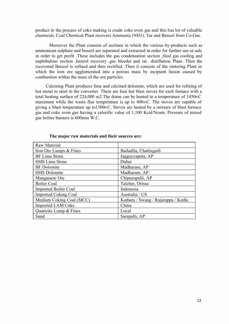
The major raw materials and their sources are:
Raw Material
Iron Ore Lumps & Fines Bailadila, Chattisgarh
BF Lime Stone Jaggayyapeta, AP
SMS Lime Stone Dubai
BF Dolomite Madharam, AP
SMS Dolomite Madharam, AP
Manganese Ore Chipurupalli, AP
Boiler Coal Talcher, Orissa
Imported Boiler Coal Indonesia
Imported Coking Coal Australia / US
Medium Coking Coal (MCC) Kathara / Swang / Rajarappa / Kedla
Imported LAM Coke China
Quartzite Lump & Fines Local
Sand Sarepalli, AP
8/13/2019 Analysis of Grain Structure in Forging
http://slidepdf.com/reader/full/analysis-of-grain-structure-in-forging 13/55
13
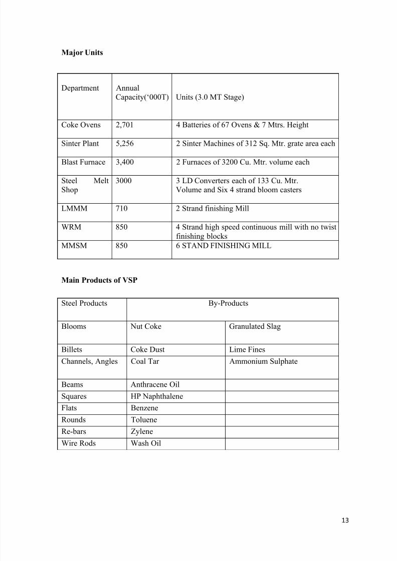
Major Units
Department Annual
Capacity(„000T) Units (3.0 MT Stage)
Coke Ovens 2,701 4 Batteries of 67 Ovens & 7 Mtrs. Height
Sinter Plant 5,256 2 Sinter Machines of 312 Sq. Mtr. grate area each
Blast Furnace 3,400 2 Furnaces of 3200 Cu. Mtr. volume each
Steel MeltShop
3000 3 LD Converters each of 133 Cu. Mtr.Volume and Six 4 strand bloom casters
LMMM 710 2 Strand finishing Mill
WRM 850 4 Strand high speed continuous mill with no twistfinishing blocks
MMSM 850 6 STAND FINISHING MILL
Main Products of VSP
Steel Products By-Products
Blooms Nut Coke Granulated Slag
Billets Coke Dust Lime Fines
Channels, Angles Coal Tar Ammonium Sulphate
Beams Anthracene Oil
Squares HP Naphthalene
Flats Benzene
Rounds Toluene
Re-bars Zylene
Wire Rods Wash Oil
8/13/2019 Analysis of Grain Structure in Forging
http://slidepdf.com/reader/full/analysis-of-grain-structure-in-forging 14/55
14
THE MAJOR DEPARTMENTS OF VSP STEEL PLANT ARE:
Raw Material Handling Plant
VSP annually requires quality raw materials viz. Iron Ore, fluxes (Lime stone,
Dolomite), coking and non-coking coals etc. to the tune of 12-13 Million Tons for producing 3 Million Tons of Liquid Steel. To handle such a large volume of incomingraw materials received from different sources and to ensure timely supply of consistentquality of feed materials to different VSP consumers, Raw Material Handling Plant servesa vital function. This unit is provided with elaborate unloading, blending, stacking &reclaiming facilities viz. Wagon Tipplers, Ground & Track Hoppers, Stock yardsCrushing Plants, Vibrating screens, Single / twin boom stackers, wheel on boom andBlender reclaimers, Stacker – cum – Reclaimer (SCR). In VSP peripheral unloading has
been adopted for the first time in the country. Coking coals are received throughconveyors directly from M/s Gangavaram Port Limited to Coal Stock Yard.
Coke ovens & Coal Chemical Plant (CO&CCP)
Blast Furnaces, the mother units of any Steel Plant require huge quantities ofstrong, hard and porous solid fuel in the form of hard metallurgical coke for supplyingnecessary heat for carrying out the reduction and refining reactions besides acting as areducing agent. At VSP there are Four Coke Oven Batteries, 7 Meter tall and having 67Ovens each. Each oven is having a volume of 41.6 cu. Meter & can hold upto 31.6 Tonsof dry coal charge. There are 4 Coke Dry Cooling Plants (CDCP) each having 4 coolingchambers. Nitrogen gas is used as the Cooling medium. The heat recovery from nitrogenis done by generating steam and expanding in two back pressure turbines to produce 7.5MW each
The Coal chemicals such as Benzole (& its products), Tar (& its products),Ammonium Sulphate etc. are extracted in Coal Chemical Plant from C.O. Gas. Afterrecovering the Coal chemicals the gas is used as a byproduct fuel by mixing it with gasessuch as BF Gas, LD Gas etc. A mechanical, Biological & chemical treatment Plant takescare of the effluents.
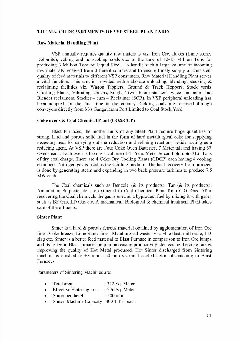
Sinter Plant
Sinter is a hard & porous ferrous material obtained by agglomeration of Iron Orefines, Coke breeze, Lime Stone fines, Metallurgical wastes viz. Flue dust, mill scale, LD
slag etc. Sinter is a better feed material to Blast Furnace in comparison to Iron Ore lumpsand its usage in Blast furnaces help in increasing productivity, decreasing the coke rate &improving the quality of Hot Metal produced. Hot Sinter discharged from Sinteringmachine is crushed to +5 mm - 50 mm size and cooled before dispatching to BlastFurnaces.
Parameters of Sintering Machines are:
Total area : 312 Sq. Meter
Effective Sintering area : 276 Sq. Meter
Sinter bed height : 500 mm
Sinter Machine Capacity : 400 T P H each
8/13/2019 Analysis of Grain Structure in Forging
http://slidepdf.com/reader/full/analysis-of-grain-structure-in-forging 15/55
15
The dust laden air from the machines are cleaned in scrubbers & electrostatic precipitators to reduce the dust content to 100 mg/ m3 level before allowing to escapeinto the atmosphere and thus helping in maintaining a clean & dust free environment.
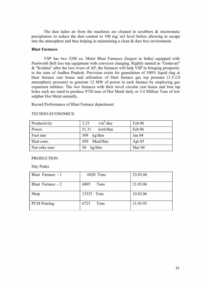
Blast Furnaces
VSP has two 3200 cu. Meter Blast Furnaces (largest in India) equipped withPaulworth Bell less top equipment with conveyor charging. Rightly named as "Godavari"& "Krishna" after the two rivers of AP, the furnaces will help VSP in bringing prosperityto the state of Andhra Pradesh. Provision exists for granulation of 100% liquid slag at
blast furnace cast house and utilization of blast furnace gas top pressure (1.5-2.0atmospheric pressure) to generate 12 MW of power in each furnace by employing gasexpansion turbines. The two furnaces with their novel circular cast house and four tapholes each are rated to produce 9720 tons of Hot Metal daily or 3.4 Million Tons of lowsulphur Hot Metal annually.
Record Performance of Blast Furnace department:
TECHNO-ECONOMICS:
Productivity 2.23 t/m /day Feb 06
Power 51.31 kwh/thm Feb 06
Fuel rate 509 kg/thm Jan 04
Heat cons. 450 Mcal/thm Apr 05
Nut coke uses 56 kg/thm Mar 04
PRODUCTION
Day Peaks
Blast Furnace - 1 6820 Tons 23.03.06
Blast Furnace - 2 6805 Tons 21.03.06
Shop 13325 Tons 10.02.06
PCM Pouring 6723 Tons 31.03.93
8/13/2019 Analysis of Grain Structure in Forging
http://slidepdf.com/reader/full/analysis-of-grain-structure-in-forging 16/55
16
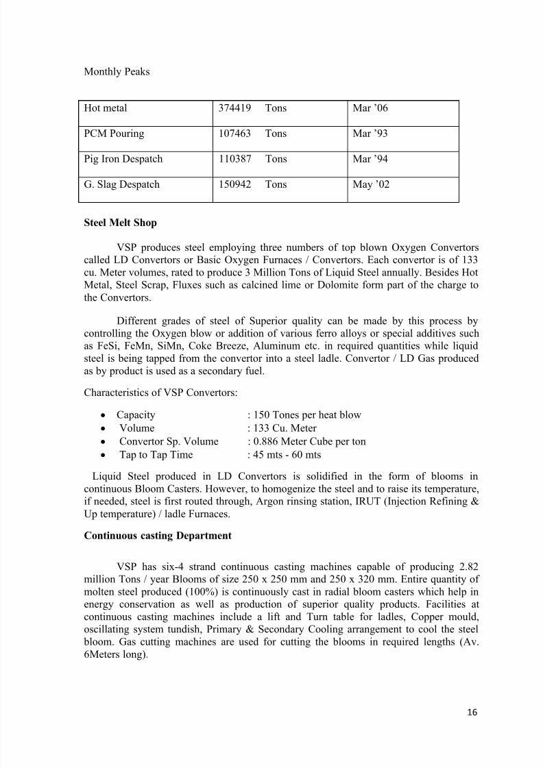
Monthly Peaks
Hot metal 374419 Tons Mar ‟06
PCM Pouring 107463 Tons Mar ‟93
Pig Iron Despatch 110387 Tons Mar ‟94
G. Slag Despatch 150942 Tons May ‟02
Steel Melt Shop
VSP produces steel employing three numbers of top blown Oxygen Convertorscalled LD Convertors or Basic Oxygen Furnaces / Convertors. Each convertor is of 133
cu. Meter volumes, rated to produce 3 Million Tons of Liquid Steel annually. Besides HotMetal, Steel Scrap, Fluxes such as calcined lime or Dolomite form part of the charge tothe Convertors.
Different grades of steel of Superior quality can be made by this process bycontrolling the Oxygen blow or addition of various ferro alloys or special additives suchas FeSi, FeMn, SiMn, Coke Breeze, Aluminum etc. in required quantities while liquidsteel is being tapped from the convertor into a steel ladle. Convertor / LD Gas producedas by product is used as a secondary fuel.
Characteristics of VSP Convertors:
Capacity : 150 Tones per heat blow
Volume : 133 Cu. Meter
Convertor Sp. Volume : 0.886 Meter Cube per ton
Tap to Tap Time : 45 mts - 60 mts
Liquid Steel produced in LD Convertors is solidified in the form of blooms incontinuous Bloom Casters. However, to homogenize the steel and to raise its temperature,if needed, steel is first routed through, Argon rinsing station, IRUT (Injection Refining &Up temperature) / ladle Furnaces.
Continuous casting Department
VSP has six-4 strand continuous casting machines capable of producing 2.82million Tons / year Blooms of size 250 x 250 mm and 250 x 320 mm. Entire quantity ofmolten steel produced (100%) is continuously cast in radial bloom casters which help inenergy conservation as well as production of superior quality products. Facilities atcontinuous casting machines include a lift and Turn table for ladles, Copper mould,oscillating system tundish, Primary & Secondary Cooling arrangement to cool the steel
bloom. Gas cutting machines are used for cutting the blooms in required lengths (Av.6Meters long).
8/13/2019 Analysis of Grain Structure in Forging
http://slidepdf.com/reader/full/analysis-of-grain-structure-in-forging 17/55
17
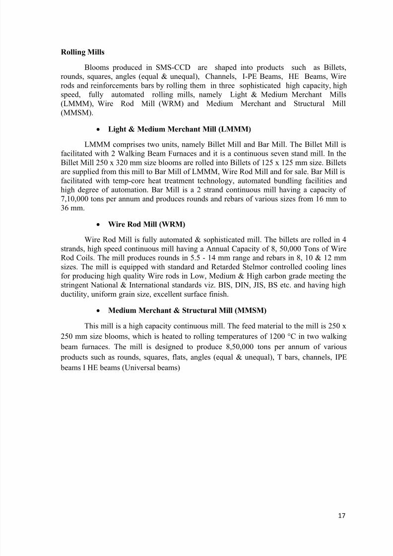
Rolling Mills
Blooms produced in SMS-CCD are shaped into products such as Billets,rounds, squares, angles (equal & unequal), Channels, I-PE Beams, HE Beams, Wirerods and reinforcements bars by rolling them in three sophisticated high capacity, high
speed, fully automated rolling mills, namely Light & Medium Merchant Mills(LMMM), Wire Rod Mill (WRM) and Medium Merchant and Structural Mill(MMSM).
Light & Medium Merchant Mill (LMMM)
LMMM comprises two units, namely Billet Mill and Bar Mill. The Billet Mill isfacilitated with 2 Walking Beam Furnaces and it is a continuous seven stand mill. In theBillet Mill 250 x 320 mm size blooms are rolled into Billets of 125 x 125 mm size. Billetsare supplied from this mill to Bar Mill of LMMM, Wire Rod Mill and for sale. Bar Mill isfacilitated with temp-core heat treatment technology, automated bundling facilities andhigh degree of automation. Bar Mill is a 2 strand continuous mill having a capacity of7,10,000 tons per annum and produces rounds and rebars of various sizes from 16 mm to36 mm.
Wire Rod Mill (WRM)
Wire Rod Mill is fully automated & sophisticated mill. The billets are rolled in 4strands, high speed continuous mill having a Annual Capacity of 8, 50,000 Tons of WireRod Coils. The mill produces rounds in 5.5 - 14 mm range and rebars in 8, 10 & 12 mmsizes. The mill is equipped with standard and Retarded Stelmor controlled cooling linesfor producing high quality Wire rods in Low, Medium & High carbon grade meeting thestringent National & International standards viz. BIS, DIN, JIS, BS etc. and having high
ductility, uniform grain size, excellent surface finish.
Medium Merchant & Structural Mill (MMSM)
This mill is a high capacity continuous mill. The feed material to the mill is 250 x
250 mm size blooms, which is heated to rolling temperatures of 1200 °C in two walking
beam furnaces. The mill is designed to produce 8,50,000 tons per annum of various
products such as rounds, squares, flats, angles (equal & unequal), T bars, channels, IPE
beams I HE beams (Universal beams)
8/13/2019 Analysis of Grain Structure in Forging
http://slidepdf.com/reader/full/analysis-of-grain-structure-in-forging 18/55
18
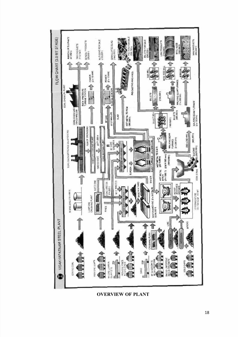
OVERVIEW OF PLANT
8/13/2019 Analysis of Grain Structure in Forging
http://slidepdf.com/reader/full/analysis-of-grain-structure-in-forging 19/55
19
ENGINEERING SHOPS & FOUNDRY
Engineering Shops & Foundry (ES&F) is a set up to meet the requirements of Ferrous& Non Ferrous Spares of different departments. The ES&F is divided into 5 Sections.
Central Machine Shop (CMS)
Steel Structural Shop(SSS)
Forge Shop (FS)
Foundry (Fdy)
Utility Equipment Repair Shop (UERS)
CENTRAL MACHINE SHOP (CMS):
Inputs:
Iron & steel castings from Foundry shop, Forgings from Forge Shop, Rolled Sections,Repair & Rectification parts, Non Ferrous Castings.
Facility available for value addition:
The machining section has over 100 major machines including heavy & light Lathes,Milling, Boring, & Planning, Slotting, Shaping, Grinding& other machines.
Lathe Machine - 1.5Mt Lathe, 3.0Mt Heavy Lathe, Vertical Turret Lathe,Relieving Lathe.
Milling Machine - Horizontal milling Machine, Vertical Milling Machine,Plano Milling Machine.
Boring Machine - Horizontal Boring Machine, Vertical Boring Machine. Drilling Machine - Column Drilling Machine, Radial Drilling Machine.
The assembly section undertakes medium repair and general over hauling ofmechanical equipment.
The heat treatment section is provided with annealing, normalizing, temperingfurnaces, carburizing furnaces
Outputs:
Shafts, pinions gears, crane wheels, rollers, machining of various assembly jobs.
STEEL STRUCTURAL SHOP (SSS)
Inputs:
Various sizes of plates, Angles, Channels, Beams, Flats, Rounds for fabrication of jobs
Facility available for value addition:
8/13/2019 Analysis of Grain Structure in Forging
http://slidepdf.com/reader/full/analysis-of-grain-structure-in-forging 20/55
20
There are two CNC Profile Gas Cutting Machines used for profile cutting, astraightening cum Bending machine used for bending sheets up to a maximum thicknessof 25mm, a hydraulic guillotine shearing machine, Combination shearing machine usedfor cutting metal sheets by shearing, a 200 ton vertical press etc.
Outputs:
All type of fabrication jobs, repair of slag pots of SMS, mfg and repair of tundishes forSMS, mfg of Scrap Boxes for SMS , hot metal Ladle for SMS, 500 Launder for SMS,
body for FMD, repair of Buckets for LMMM,WRM
FORGE SHOP (FS)
Forging is the hot working of metals performed by means of hammer blown orunder the pressure of press. Various kinds of machine parts of different shapes & sizes are
made by forging operation.
Inputs: Ingots from foundry, blooms from SMS, round rods from mills
Facility available for value addition:
The shop is designed for production of forging for shafts, coupling flanges etc andalso of forged shapes such as crusher hammer heads, special bolts, nuts etc. There isfacility for repair of and testing chains is existing. The annual production from the shop is
about 2400 tones. In heavy forging section open die forgings of long shafts, gear blanks,coupling etc is made with the help of 2 ton & 3 ton bridge type pneumatic hammers. Eachhammer will be provided twin chamber heating surface are provided. A 2 ton drop stamphammer with a heating furnace trimming press etc is provided for stamping. For cuttingthem to size a cold saw, a billet shear and gas cutting facilities are provided. For stressrelieving a bogie type annealing furnace is provided.
Output: Finished forgings
Main products-Plain shafts up to 300 mm dia & 3000 mm lengthStepped shafts (300dia max, dia 70 min up to 4000 mm length)Gear blanksCrane wheels (800 dia max, dia 300 min)V bends & U bendsTap hole drill rods etc.
8/13/2019 Analysis of Grain Structure in Forging
http://slidepdf.com/reader/full/analysis-of-grain-structure-in-forging 21/55
21
FOUNDRY (FDY)
Inputs:
Pig Iron, M.S. Scrap, Ferro Alloys, Sodium Silicate, Silica Sand, CO2 gas, Moulding
additives etc
Facility available for value addition:
The wood work shop manufactures patterns for Foundries. The principalequipment for pattern making are Saws, Disc Grinding, Wood working Lathes, adequatefacilities are provided for saw grinding, painting, Timber And Pattern Storage etc. Thefoundry shop has different bays for moulding and casting. Raw material is kept at one endand this is used for preparation of mould and casting. The foundry shop also has a arcfurnace and two induction furnaces for melting the raw materials. The arc furnace has acapacity of 8-10 tons while the induction furnace has a capacity of 5-30 tons.
Outputs:
The main Products are Steel, Cast Iron & Non Ferrous Castings, EmergencyContainers, and Bull gear for SMS, Hot metal runners, Ladle paw for Blast Furnace. Cokeroll liners, Non Ferrous casting like bushes (below 20 kg) etc
UTILITY EQUIPMENT REPAIR SHOP (UERS)
Inputs:
Sheets, Plates, Channels, Angles, Beams, Billets, Rounds from Forge Shop formanufacturing Shafts, Steel & Iron casting
Facility available for value addition:
Repair of Steam exhausters for SMS ,supply of Cones & Ducts of various sizes,Manufacturing of impellers to various departments, build up & machining of variouscomponents, reclamation jobs like valve repairs, Conveyor Idlers, PCM Rollers etc.
8/13/2019 Analysis of Grain Structure in Forging
http://slidepdf.com/reader/full/analysis-of-grain-structure-in-forging 22/55
22
Introduction to Metal Manufacturing Process
Manufacturing is the production of goods for use or sale using labor and machines, tools, chemical and biological processing, or formulation. The term may refer to a rangeof human activity, from handicraft to high tech, but is most commonly applied to
industrial production, in which raw materials are transformed into finished goods on alarge scale. Such finished goods may be used for manufacturing other, more complex
products, such as aircraft, household appliances or automobiles, or sold to wholesalers, who in turn sell them to retailers, who then sell them to end users – the "consumers".
Manufacturing takes turns under all types of economic systems. In a free marketeconomy, manufacturing is usually directed toward the mass production of products forsale to consumers at a profit. In a collectivist economy, manufacturing is more frequentlydirected by the state to supply a centrally planned economy. In mixed market economies,manufacturing occurs under some degree of government regulation.
Modern manufacturing includes all intermediate processes required for the productionand integration of a product's components. Some industries, such as semiconductor andsteel manufacturers use the term fabrication instead.
The manufacturing sector is closely connected with engineering and industrialdesign. Examples of major manufacturers in North America include General MotorsCorporation, General Electric, and Pfizer. Examples in Europe include VolkswagenGroup, Siemens, and Michelin. Examples in Asia include Toyota, Samsung, andBridgestone.
History and development
In its earliest form, manufacturing was usually carried out by a singleskilled artisan with assistants. Training was by apprenticeship. In much ofthe pre-industrial world the guild system protected the privileges and tradesecrets of urban artisans.
Before the Industrial Revolution, most manufacturing occurred in ruralareas, where household-based manufacturing served as a supplementalsubsistence strategy to agriculture (and continues to do so in places).Entrepreneurs organized a number of manufacturing households into asingle enterprise through the putting-out system.
Toll manufacturing is an arrangement whereby a first firm with specializedequipment processes.
Types of Manufacturing Processes:
Manufacturing processes are the steps through which raw materials are transformedinto a product. The manufacturing processes can be broadly classified into variouscategories... The selection of a particular process from a wide range of choices for a givenapplication requires a hierarchical classification of the processes. Depicts how the shapingfamily can be expanded in different classes such as casting, deformation, moulding,composite and powder processing, and prototyping. Next moulding is a class can be
enlarged into a number of member processes such as compression, rotational, transfer,injection moulding, etc. Lastly, each member process can be identified with a number of
8/13/2019 Analysis of Grain Structure in Forging
http://slidepdf.com/reader/full/analysis-of-grain-structure-in-forging 23/55
23
attributes, which would facilitate the selection of a member process for a given materialdimension, level of requisite tolerances and so on.
A brief description of the seven broad categories of the manufacturing processes:-
Casting Moulding
Forging
Forming
Rolling
Drawing
Sintering
Machining
CASTING:
Most of the manufactured parts start its journey with casting process. In atypical casting process, metal is first heated in a furnace until it melts and then the moltenmetal is poured into a mold so that the liquid metal takes the shape of the mold cavity,which is the final shape of the part. Once the liquid metal in the mold cavity solidifies, themold is broken or opened to take the final part out of the mold cavity, liquefying ofmetallic material by properly heating it in a suitable furnace.
• pouring of hot molten metal into a previously made colder mould cavity,
• Extraction of the solidified cast from the mould cavity
The various types of castings are as follows –
Centrifugal casting Continuous casting Die casting Evaporative-pattern casting Full-mold casting Lost-foam casting Investment casting (lost wax casting) Low pressure Permanent mold casting Plastic mold Resin casting Sand casting Shell molding Slush or slurry Spray forming
8/13/2019 Analysis of Grain Structure in Forging
http://slidepdf.com/reader/full/analysis-of-grain-structure-in-forging 24/55
24
Advantages
It is economical with very little wastage. Even the extra metal produced duringeach casting can be re-melted and reused.
It can produce parts with complex geometrical features such as internal cavities,
hollow sections with fair dimensional accuracy. Casting can be used to make very small to extremely large and complex parts
It is possible to cast metallic materials with very low to reasonably high meltingtemperatures. Further, the mechanical properties of a cast are usually isotropic.
Disadvantages
Accurate shape and size are not found
Not suitable for large skill production
Poor Surface finish
MOULDING
Moulding is the process of manufacturing by shaping pliable raw material usinga rigid frame or model called a pattern.
A mould is a hollowed-out block that is filled with a liquid like plastic, glass, metal, or ceramic raw materials. The liquid hardens or sets inside the mold, adopting itsshape. A mold is the counterpart to a cast. The manufacturer who makes the molds iscalled the moldmaker. A release agent is typically used to make removal of the
hardened/set substance from themold easier.
The various types of mouldings are as follows –
Blow molding Compaction plus sintering Compression molding Expandable bead molding Extrusion molding Foam molding Injection molding
Laminating Reaction injection molding Matched mold Matrix molding Plastic moulding Pressure plug assist molding Rotational molding Transfer molding Thermoforming
8/13/2019 Analysis of Grain Structure in Forging
http://slidepdf.com/reader/full/analysis-of-grain-structure-in-forging 25/55
25
Advantages of Molding
High Production rates
Design flexibility
Repeatability within tolerances
Can process a wide range of materials Relatively low labor
Little to no finishing of parts
Minimum scrap losses
Disadvantages of Molding
High initial equipment investment
High startup and running costs possible
Part must be designed for effective molding
Accurate cost prediction for molding job is difficult
FORGING:
Forging is a manufacturing process involving the shaping of metal using localizedcompressive forces. Forging is often classified according to the temperature at which it is
performed: "cold", "warm", or "hot" forging. Forged parts can range in weight from lessthan a kilogram to 580 metric tons. Forged parts usually require further processing toachieve a finished part.
A Forged metal can result in the following:
Increase length, decrease cross-section, called drawing out the metal.
Decrease length, increase cross-section, called upsetting the metal.
Change length, change cross-section, by squeezing in closed impression dies. Thisresults in favorable grain flow for strong parts.
The various types of forgings are as follows:
Press forging
Drop forging Machine forging Roll forging open die forging Closed die forging
Advantage and disadvantage:
Forging can produce a piece that is stronger than an equivalent cast or machined part. As the metal is shaped during the forging process, its internal grain deformsto follow the general shape of the part. As a result, the grain is continuous
throughout the part, giving rise to a piece with improved strength characteristics.
8/13/2019 Analysis of Grain Structure in Forging
http://slidepdf.com/reader/full/analysis-of-grain-structure-in-forging 26/55
26
Some metals may be forged cold, but iron and steel are almost always hot forged.Hot forging prevents the work hardening that would result from cold forging,which would increase the difficulty of performing secondary machiningoperations on the piece.
Also, while work hardening may be desirable in some circumstances, other
methods of hardening the piece, such as heat treating, are generally moreeconomical and more controllable.
Alloys that are amenable to precipitation hardening, such as most aluminiumalloys and titanium, can be hot forged, followed by hardening.
Production forging involves significant capital expenditure for machinery,tooling, facilities and personnel. In the case of hot forging, a high-temperaturefurnace (sometimes referred to as the forge) is required to heat ingots or billets.Owing to the massiveness of large forging hammers and presses and the parts theycan produce, as well as the dangers inherent in working with hot metal, a special
building is frequently required to house the operation. In the case of drop forgingoperations, provisions must be made to absorb the shock and vibration generated
by the hammer.
Most forging operations use metal-forming dies, which must be preciselymachined and carefully heat-treated to correctly shape the workpiece, as well as towithstand the tremendous forces involved.
FORMING
Forming or metal forming, is the metalworking process of fashioning metal partsand objects through mechanical deformation; the workpiece is reshaped without adding or
removing material, and its mass remains unchanged.
Forming operates on the materialsscience principle of plastic deformation, where the physical shape of a material is permanently deformed.
Metal forming tends to have more uniform characteristics across its sub- processes than its contemporary processes, cutting and joining. On the industrial scale,forming is characterized by:
Very high required loads and stresses, between 50 and 2500 N/mm2 (7-360 ksi) Large, heavy, and expensive machinery in order to accommodate such high
stresses and loads
Production runs with many parts, to maximize the economy of production andcompensate for the expense of the machine tools
Forming processes tend to be typified by differences in effective stresses. Thesecategories and descriptions are highly simplified, since the stresses operating at alocal level in any given process are very complex and may involve many varietiesof stresses operating simultaneously, or it may involve stresses which change overthe course of the operation
8/13/2019 Analysis of Grain Structure in Forging
http://slidepdf.com/reader/full/analysis-of-grain-structure-in-forging 27/55
27
Compressive forming Tensile forming‟ Combined tensile and compressive forming Bending Shearing
Extrusion Pressing Stamping Bending Shearing
Advantage:
Product performance is improved over other manufacturing processes as theforming process rearranges the grain structure to follow the part configuration.
This favorable characteristic eliminates the potential for porosity fatigues,increases over-all strength performance (shear strength, etc.) and reduces risk ofother types of material integrity.
Production costs are reduced by the high speed manufacturing process. Speedsrange from 50 pieces per minute to 400 pieces per minute on the cold heading
process.
Surface finish is improved versus machined surfaces.
ROLLING
Rolling is a type of motion that combines rotation (commonly, of an axiallysymmetric object) and translation of that object with respect to a surface (either one or theother moves), such that, if ideal conditions exist, the two are in contact with each otherwithout sliding.
Rolling is achieved by a rotational speed at the line or point of contact which is equal tothe translational speed. When no sliding takes place the rolling motion is referred to as'pure rolling'. In practice, due to small deformations at the contact area, some sliding doesoccur. Nevertheless, rolling resistance is much lower than sliding friction, and thus,rolling objects, typically require much less energy to be moved than sliding ones. As a
result, such objects will more easily move, if they experience a force with a componentalong the surface, for instance gravity on a tilted surface; wind; pushing; pulling; anengine. Unlike most axially symmetrical objects, the rolling motion of a cone is such thatwhile rolling on a flat surface, its center of gravity performs a circular motion, rather thana linear one. Rolling objects are not necessarily axially-symmetrical. Two well knownnon-axially-symmetrical rollers are the Reuleaux triangle and the Meissner bodies. Objects with corners, such as dice, roll by successive rotations about the edge or cornerwhich is in contact with the surface.
8/13/2019 Analysis of Grain Structure in Forging
http://slidepdf.com/reader/full/analysis-of-grain-structure-in-forging 28/55
28
The various types of forgings are as follows –
Cold rolling Hot rolling Sheet metal
Shape Shape Ring Transverse Cryorolling Orbital Cross-rolling Thread
DRAWING
Drawing is a metalworking process which uses tensile forces to stretch metal. It is broken up into two types: sheet metal drawing and wire, bar, and tube drawing. Thespecific definition for sheet metal drawing is that it involves plastic deformation over acurved axis. For wire, bar, and tube drawing the starting stock is drawn through a die toreduce its diameter and increase its length. Drawing is usually done at room temperature,thus classified a cold working process, however it may be performed at elevatedtemperatures to hot work large wires, rods or hollow sections in order to reduce forces.
The various types of forgings are as follows :
Sheet metal Deep drawing Bar drawing Tube drawing Wire drawing Plastic drawing
SINTERING
Sintering is a method used to create objects from powders. It is based on atomic
diffusion. Diffusion occurs in any material above absolute zero, but it occurs much fasterat higher temperatures. In most sintering processes, the powdered material is held in amold and then heated to a temperature below the melting point. The atoms in the powder
particles diffuse across the boundaries of the particles, fusing the particles together andcreating one solid piece. Because the sintering temperature does not have to reach themelting point of the material, sintering is often chosen as the shaping process formaterials with extremely high melting points such as tungsten and molybdenum.
Sintering is traditionally used for manufacturing ceramic objects but finds applications inalmost all fields of industry. The study of sintering and of powder-related processes isknown as powder metallurgy. A simple, intuitive example of sintering can be observed
when ice cubes in a glass of water adhere to each other.
8/13/2019 Analysis of Grain Structure in Forging
http://slidepdf.com/reader/full/analysis-of-grain-structure-in-forging 29/55
29
The various types of forgings are as follows –
General sintering
Ceramic sintering
Plastics sintering
Liquid phase sintering Electric current assisted sintering
Spark plasma sintering
Pressure less sintering
Advantages
1. Very high level of purity and uniformity in starting materials.2. Stabilizations of the details of respective operations, by control of grain
size during the input stages.3. Absence of binding contact between segregated powder particles or
“inclusions‟‟ (called sintering) as often occurs in melting process. 4. No deformation needed to produce directional elongation of grains.
MACHINING
Machining is any of various processes in which a piece of raw material iscut into a desirable‟s final shape and size by a controlled material-removal
process. The many processes that have this common theme, controlled materialremoval, are today collectively known as subtractive manufacturing, in distinctionfrom processes of controlled material addition, which are known as additivemanufacturing.
The precise meaning of the term "machining" has evolved over the pasttwo centuries as technology has advanced. During the Machine Age, it referred to(what we today might call) the "traditional" machining processes, such as turning,
boring, drilling, milling, broaching, sawing, shaping, planning, reaming, andtapping. In these "traditional" or "conventional" machining processes, machinetools, such as lathes, milling machines, drill presses, or others, are used with asharp cutting tool to remove material to achieve a desired geometry. Since theadvent of new technologies such as electrical discharge machining, electrochemical machining, electron beam machining, photochemical machining,
and ultrasonic machining, the retronym "conventional machining" can be used todifferentiate those classic technologies from the newer ones. In current usage, theterm "machining" without qualification usually implies the traditional machining
processes.
Machining is a part of the manufacture of many metal products, but it canalso be used on materials such as wood, plastic, ceramic, and composites. A
person who specializes in machining is called a machinist. A room, building, orcompany where machining is done is called a machine shop. Machining can be a
business, a hobby, or both. Much of modern day machining is carried out bycomputer numerical control (CNC), in which computers are used to control the
movement and operation of the mills, lathes, and other cutting machines.

8/13/2019 Analysis of Grain Structure in Forging
http://slidepdf.com/reader/full/analysis-of-grain-structure-in-forging 30/55
30
Advantages
The machining processes can produce a wide variety of dimensions with fine formaccuracy.
Almost all kind of engineering materials and plastics can be machined,
The machining processes can be easily automated to achieve an excellent productivity,
The role of the process parameters and their control to obtain a desired part withgood
Dimensional accuracy is well established in most of the machining processes.
8/13/2019 Analysis of Grain Structure in Forging
http://slidepdf.com/reader/full/analysis-of-grain-structure-in-forging 31/55
31
Introduction to Forging:
Forging is a manufacturing process involving the shaping of metal using localizedcompressive forces. Forging is often classified according to the temperature at which it is
performed: "cold", "warm", or "hot" forging. Forged parts can range in weight from less
than a kilogram to 580 metric tons. Forged parts usually require further processing toachieve a finished part.
Processes:
There are many different kinds of forging processes available; however they can begrouped into three main classes:
Drawn out: length increases, cross-section decreases Upset: length decreases, cross-section increases Squeezed in closed compression dies: produces multidirectional flow
Drop forging:
Drop forging is a forging process where a hammer is raised and then "dropped"onto the work-piece to deform it according to the shape of the die. There are two types ofdrop forging: open-die drop forging and closed-die drop forging. As the names imply, thedifference is in the shape of the die, with the former not fully enclosing the workpiece,while the latter does.
Open-die drop forging
Open-die drop forging (with two dies) of an ingot to be further processed into awheel. Open-die forging is also known as smith forging. In open-die forging, a hammerstrikes and deforms the work-piece, which is placed on a stationary anvil. Open-dieforging gets its name from the fact that the dies (the surfaces that are in contact with thework-piece) do not enclose the work-piece, allowing it to flow except where contacted bythe dies. Therefore the operator, or a robot, needs to orient and position the work-piece toget the desired shape. The dies are usually flat in shape, but some have a specially shapedsurface for specialized operations. For example, a die may have a round, concave, orconvex surface or be a tool to form holes or be a cut-off tool.
Open-die forging lends itself to short runs and is appropriate for art smithing andcustom work. In some cases, open-die forging may be employed to rough-shape ingots to
prepare them for subsequent operations. Open-die forging may also orient the grain toincrease strength in the required direction.
Impression-die drop forging
Impression-die forging is also called closed-die forging. In impression-dieforging, the metal is placed in a die resembling a mold, which is attached to the anvil.Usually, the hammer die is shaped as well. The hammer is then dropped on theworkpiece, causing the metal to flow and fill the die cavities. The hammer is generally in
contact with the workpiece on the scale of milliseconds. Depending on the size andcomplexity of the part, the hammer may be dropped multiple times in quick succession.
8/13/2019 Analysis of Grain Structure in Forging
http://slidepdf.com/reader/full/analysis-of-grain-structure-in-forging 32/55
32
Excess metal is squeezed out of the die cavities, forming what are referred to as flash. Theflash cools more rapidly than the rest of the material; this cool metal is stronger than themetal in the die, so it helps prevent more flash from forming. This also forces the metal tocompletely fill the die cavity. After forging, the flash is removed.
In commercial impression-die forging, the workpiece is usually moved through aseries of cavities in a die to get from an ingot to the final form. The first impression isused to distribute the metal into the rough shape in accordance to the needs of latercavities; this impression is called an edging, fullering, or bending impression. Thefollowing cavities are called blocking cavities, in which the piece is working into a shapethat more closely resembles the final product. These stages usually impart the workpiecewith generous bends and large fillets. The final shape is forged in a final or finisherimpression cavity. If there is only a short run of parts to be done, then it may be moreeconomical for the die to lack a final impression cavity and instead machine the finalfeatures.
Impression-die forging has been improved in recent years through increasedautomation which includes induction heating, mechanical feeding, positioning andmanipulation, and the direct heat treatment of parts after forging.
One variation of impression-die forging is called fleshless forging, or true closed-die forging. In this type of forging, the die cavities are completely closed, which keeps theworkpiece from forming flash. The major advantage to this process is that less metal islost to flash. Flash can account for 20 to 45% of the starting material. The disadvantagesof this process include additional cost due to a more complex die design and the need for
better lubrication and workpiece placement.
There are other variations of part formation that integrate impression-die forging.One method incorporates casting a forging perform from liquid metal. The casting isremoved after it has solidified, but while still hot. It is then finished in a single cavity die.The flash is trimmed, and then the part is quenching hardened. Another variation followsthe same process as outlined above, except perform is produced by the sprayingdeposition of metal droplets into shaped collectors (similar to the Osprey process).
Closed-die forging has a high initial cost due to the creation of dies and requireddesign work to make working die cavities. However, it has low recurring costs for each
part, thus forgings become more economical with more volume. This is one of the major
reasons closed-die forgings are often used in the automotive and tool industry. Anotherreason forgings are common in these industrial sectors is that forgings generally haveabout a 20 percent higher strength-to-weight ratio compared to cast or machined parts ofthe same material.
Press forging
Press forging works by slowly applying a continuous pressure or force, whichdiffers from the near-instantaneous impact of drop-hammer forging. The amount of timethe dies are in contact with the workpiece is measured in seconds (as compared to themilliseconds of drop-hammer forges). The press forging operation can be done either cold
or hot.
8/13/2019 Analysis of Grain Structure in Forging
http://slidepdf.com/reader/full/analysis-of-grain-structure-in-forging 33/55
33
The main advantage of press forging, as compared to drop-hammer forging, is itsability to deform the complete workpiece. Drop-hammer forging usually only deforms thesurfaces of the workpiece in contact with the hammer and anvil; the interior of theworkpiece will stay relatively undeformed. Another advantage to the process includes theknowledge of the new part's strain rate. We specifically know what kind of strain can be
put on the part, because the compression rate of the press forging operation is controlled.
There are a few disadvantages to this process, most stemming from the workpiece being in contact with the dies for such an extended period of time. The operation is atime-consuming process due to the amount and length of steps. The workpiece will coolfaster because the dies are in contact with workpiece; the dies facilitate drastically moreheat transfer than the surrounding atmosphere. As the workpiece cools it becomesstronger and less ductile, which may induce cracking if deformation continues. Thereforeheated dies are usually used to reduce heat loss, promote surface flow, and enable the
production of finer details and closer tolerances. The workpiece may also need to bereheated.
When done in high productivity, press forging is more economical than hammerforging. The operation also creates closer tolerances. In hammer forging a lot of the workis absorbed by the machinery, when in press forging, the greater percentage of work isused in the work piece. Another advantage is that the operation can be used to create anysize part because there is no limit to the size of the press forging machine. New pressforging techniques have been able to create a higher degree of mechanical and orientationintegrity. By the constraint of oxidation to the outer layers of the part, reduced levels ofmicrocracking occur in the finished part.
Press forging can be used to perform all types of forging, including open-die andimpression-die forging. Impression-die press forging usually requires less draft than dropforging and has better dimensional accuracy. Also, press forgings can often be done in
one closing of the dies, allowing for easy automation.
Upset forging:
Upset forging increases the diameter of the workpiece by compressing its length.Based on number of pieces produced, this is the most widely used forging process. A fewexamples of common parts produced using the upset forging process are engine valves,couplings, bolts, screws, and other fasteners.
Upset forging is usually done in special high-speed machines called crank presses, but upsetting can also be done in a vertical crank press or a hydraulic press. The machinesare usually set up to work in the horizontal plane, to facilitate the quick exchange ofworkpieces from one station to the next. The initial workpiece is usually wire or rod, butsome machines can accept bars up to 25 cm (9.8 in) in diameter and a capacity of over1000 tons. The standard upsetting machine employs split dies that contain multiplecavities. The dies open enough to allow the workpiece to move from one cavity to thenext; the dies then close and the heading tool, or ram, then moves longitudinally againstthe bar, upsetting it into the cavity. If all of the cavities are utilized on every cycle, then afinished part will be produced with every cycle, which makes this process advantageous
for mass production.
8/13/2019 Analysis of Grain Structure in Forging
http://slidepdf.com/reader/full/analysis-of-grain-structure-in-forging 34/55
34
These rules must be followed when designing parts to be upset forged:
The length of unsupported metal that can be upset in one blow without injurious buckling should be limited to three times the diameter of the bar.
Lengths of stock greater than three times the diameter may be upset successfully,
provided that the diameter of the upset is not more than 1.5 times the diameter ofthe stock.
In an upset requiring stock length greater than three times the diameter of the stock, andwhere the diameter of the cavity is not more than 1.5 times the diameter of the stock, thelength of unsupported metal beyond the face of the die must not exceed the diameter ofthe bar.
Automatic hot forging
The automatic hot forging process involves feeding mill-length steel bars
(typically 7 m (23 ft) long) into one end of the machine at room temperature and hotforged products emerge from the other end. This all occurs rapidly; small parts can bemade at a rate of 180 parts per minute (ppm) and larger can be made at a rate of 90 ppm.The parts can be solid or hollow, round or symmetrical, up to 6 kg (13 lb), and up to18 cm (7.1 in) in diameter. The main advantages to this process are its high output rateand ability to accept low-cost materials. Little labor is required to operate the machinery.
There is no flash produced so material savings are between 20 and 30% overconventional forging. The final product is a consistent 1,050 °C (1,920 °F) so air coolingwill result in a part that is still easily machinable (the advantage being the lack ofannealing required after forging). Tolerances are usually ±0.3 mm (0.012 in), surfaces are
clean, and draft angles are 0.5 to 1°. Tool life is nearly double that of conventionalforging because contact times are on the order of 0.06 second. The downside is that this
process is only feasible on smaller symmetric parts and cost; the initial investment can beover $10 million, so large quantities are required to justify this process.
The process starts by heating the bar to 1,200 to 1,300 °C (2,192 to 2,372 °F) inless than 60 seconds using high-power induction coils. It is then descaled with rollers,sheared into blanks, and transferred through several successive forming stages, duringwhich it is upset, preformed, final forged, and pierced (if necessary). This process canalso be coupled with high-speed cold-forming operations. Generally, the cold formingoperation will do the finishing stage so that the advantages of cold-working can be
obtained, while maintaining the high speed of automatic hot forging.
Examples of parts made by this process are: wheel hub unit bearings, transmissiongears, tapered roller bearing races, stainless steel coupling flanges, and neck rings for LPgas cylinders. Manual transmission gears are an example of automatic hot forging used inconjunction with cold working.
Roll forging
Roll forging is a process where round or flat bar stock is reduced in thickness andincreased in length. Roll forging is performed using two cylindrical or semi-cylindricalrolls, each containing one or more shaped grooves. A heated bar is inserted into the rolls
8/13/2019 Analysis of Grain Structure in Forging
http://slidepdf.com/reader/full/analysis-of-grain-structure-in-forging 35/55
35
and when it hits a stop the rolls rotate and the bar is progressively shaped as it is rolledthrough the machine. The piece is then transferred to the next set of grooves or turnedaround and reinserted into the same grooves. This continues until the desired shape andsize is achieved. The advantage of this process is there is no flash and it imparts afavorable grain structure into the work-piece.
Examples of products produced using this method include axles, tapered leversand leaf springs.
Net-shape and near-net-shape forging
This process is also known as precision forging. It was developed to minimizecost and waste associated with post-forging operations. Therefore, the final product froma precision forging needs little or no final machining. Cost savings are gained from theuse of less material, and thus less scrap, the overall decrease in energy used, and thereduction or elimination of machining. Precision forging also requires less of a draft, 1° to
0°. The downside of this process is its cost; therefore it is only implemented if significantcost reduction can be achieved.
Induction forging
Unlike the above processes, induction forging is based on the type of heating styleused. Many of the above processes can be used in conjunction with this heating method.
8/13/2019 Analysis of Grain Structure in Forging
http://slidepdf.com/reader/full/analysis-of-grain-structure-in-forging 36/55
36
Forging equipment & furnaces:
Equipment:
1. FORGING HAMMER OR DROP HAMMER
a. Board hammerb. Power hammerc. Impact hammerd. Industrial forged steel hammere. Swing type hammerf. Fixed type hammers
a. Board Hammer or forging hammer
The upper die and ram are raised by friction rolls gripping the board
After realizing the board , the ram falls under gravity to produce the blowenergy
The hammer can strike between 60 to 150 blows per minute depending onsize and capacity.
The board hammer is an energy restricted machine. The blow energysupplied equal to the potential energy due to the weight and the height ofthe fall.
Potential energy = mghWhere m= mass
g =acceleration of gravity
h= height of drop The energy will be delivered to the metal work piece to produce plastic
deformation.It provides rapid impact blows to the surface of the metal. The dies are divided in twohalves. The lower die is fixed to anvil and the upper die moves up and down. The energy(from the gravity drop) is absorbed into the metal, in which the maximum impact is onthe metal surface. Dies are expensive being accurately machined from special alloys(susceptible to thermal shock). Drop forging is good for mass production for complexshape.
b. Power hammer
Power hammer provides greater capacity, in which the ram is acceleratedon the down stroke by steam or air pressure in addition to gravity.
Steam or air pressure is also used to raise the ram on the upstroke. The total energy supplied to the blow in a power drop hammer is given by
W = 1/2 mv2 + pAH = (mg=pA)H
Wherem=mass
v=velocity of ram at start of deformationg=acceleration of gravity
p=air or steam pressure acting on ram cylinder on downstroke
8/13/2019 Analysis of Grain Structure in Forging
http://slidepdf.com/reader/full/analysis-of-grain-structure-in-forging 37/55
37
A= area of ram cylinderH=height of the ram drop
c. Impact hammer
These hammers are manufactured using advanced techniques and quality rawmaterials in compliance with the international quality standards of hammersmanufacturing. Moreover, manufactured product undergoes strict quality inspection
procedure, additionally available at cost effective rates. These hammers are extensivelyused in the steel mining and mineral processing industry, sugar industry, cement industry,etc.
Features:
Sturdy construction
Easy to handle
Durable
d. Industrial forged steel hammer
These hammers are available in a wide variety of shapes and sizes. For thefabrication of these products our professionals make use of optimum quality basicmaterial and most modern technology. Forged steel hammers are highly durable and easyto handle. We offer the product to our clients at a reasonable rate.
Features:
Available in different sizes
Durability
Dynamically balanced
e. Swing type of hammer
These hammers are manufactured from mild steel plates, cast steel and forged steel.The complete product range is manufactured using high quality raw material and specialhard facing alloys with high precision under expert supervision. These hammers find
application in many industries like mining & mineral processing industry, sugar industry,cement & steel industry.
Features:
Long lasting usage Optimum performance Excellent workmanship
8/13/2019 Analysis of Grain Structure in Forging
http://slidepdf.com/reader/full/analysis-of-grain-structure-in-forging 38/55
38
f. Fixed type hammers
For the manufacturing process of these products rich quality alloys and raw
material are procured from the reliable and trusted vendors of the industry. This product
range is being tested by our experienced controllers to avoid flaws. In order to meet thespecific requirements of our esteemed clients
Features:
Robust construction
Long life
Corrosion resistant
2. FORGING PRESSES
A forging press, often just called a press, is used for press forging. Thereare two main types:
a. Mechanical presses
Mechanical presses function by using cams, cranks and/or toggles to produce a preset (a predetermined force at a certain location in the stroke) and reproducible stroke.
Due to the nature of this type of system, different forces are available at different stroke positions. Mechanical presses are faster than their hydraulic counterparts (up to 50 strokes per minute). Their capacities range from 3 to 160 MN (300 to 18,000 short tons-forces).
b. Hydraulic presses.
Hydraulic presses use fluid pressure and a piston to generate force. Theadvantages of a hydraulic press over a mechanical press are its flexibility and greatercapacity. The disadvantages include a slower, larger, and costlier machine to operate. Theroll forging, upsetting, and automatic hot forging processes all use specialized machinery.
Forging furnace:
CHAMBER FURNACE:
Working principle:
Chamber Furnace is offered for a range of heat-treatment applications includingstress reliving, normalizing, hardening and tempering. Effective insulation reduces heatloss into the work environment and aids in faster heat-up.
Heating source:
Chamber furnaces utilize electrical heating elements.
8/13/2019 Analysis of Grain Structure in Forging
http://slidepdf.com/reader/full/analysis-of-grain-structure-in-forging 39/55
39
Control:
Chamber furnaces are designed to provide consistent results through uniformheating, accurate temperature control and control of furnace atmosphere. Each furnace isfitted with standard and special accessories including vertical doors fans, cooling
ventures, racks, baskets, loading devices, quench systems, various controlledatmospheres, special thermocouples, temperature controllers/recorders and alarms.Temperature range is 5000 C to 16000C
PIT FURNACE
A furnace made in pit for melting metal for taking casting process is called a pitfurnace.
Working principle
The pit furnace consists of a cylindrical steel shell, closed at the bottom with agate and covered with a removable lid. The shell is lined with refractory bricks frominside .Sometimes the furnace is completely made in brick work instead of a steel shall.The draft of the air through the furnace may be a natural draft for low meltingtemperature metals but a force draft with the help of a blower to accelerate the melting
process in case of higher melting temperature metals and alloys.
To prepare the furnace for melting, a deep bed pf coke is kindled and allowed to burn until a state of good combustion is attained .Some of the coke is removed to make place for the crucible .The crucible is then lowered into furnace .The coke is replaced andadditional coke is put to surround the crucible on all sides. Metal is then charged in the
crucible and the furnace lid is replaced to give natural draft .When the metal melts andreaches the desired temperature .The crucible is removed from the furnace with speciallong handle tongs. De -gas and de-oxidize the metal when necessary.
Control
Digital, microprocessor based, thermocouple
actuated, indicating temperature controller
Modulating burner on gas furnaces
Motor control push buttons and on-off heat switch
LED pilot light
Electric Furnace
Adjustable, thermocouple actuated, manual reset
excess temperature interlock
Separate heating element control contactors
Door interlock switch turns off power to heating
elements when door is opened; restores power
when door is closed Gas Furnace
Adjustable, thermocouple actuated, manual reset
excess temperature interlock
Electronic flame safeguard protection
8/13/2019 Analysis of Grain Structure in Forging
http://slidepdf.com/reader/full/analysis-of-grain-structure-in-forging 40/55
40
Combustion air blower with air flow safety switch
Purge timer
High and low gas pressure switches
Two pilot safety shutoff valves with leak test stations
Two main safety shutoff valves with leak test stations*
Valve position indicator on main safety shutoff valves
Over 400,000 BTU/HR safety shutoff valve interlocked
with purge timer
MUFFLE FURNACE/TUBULAR FURNACE
Working principle:
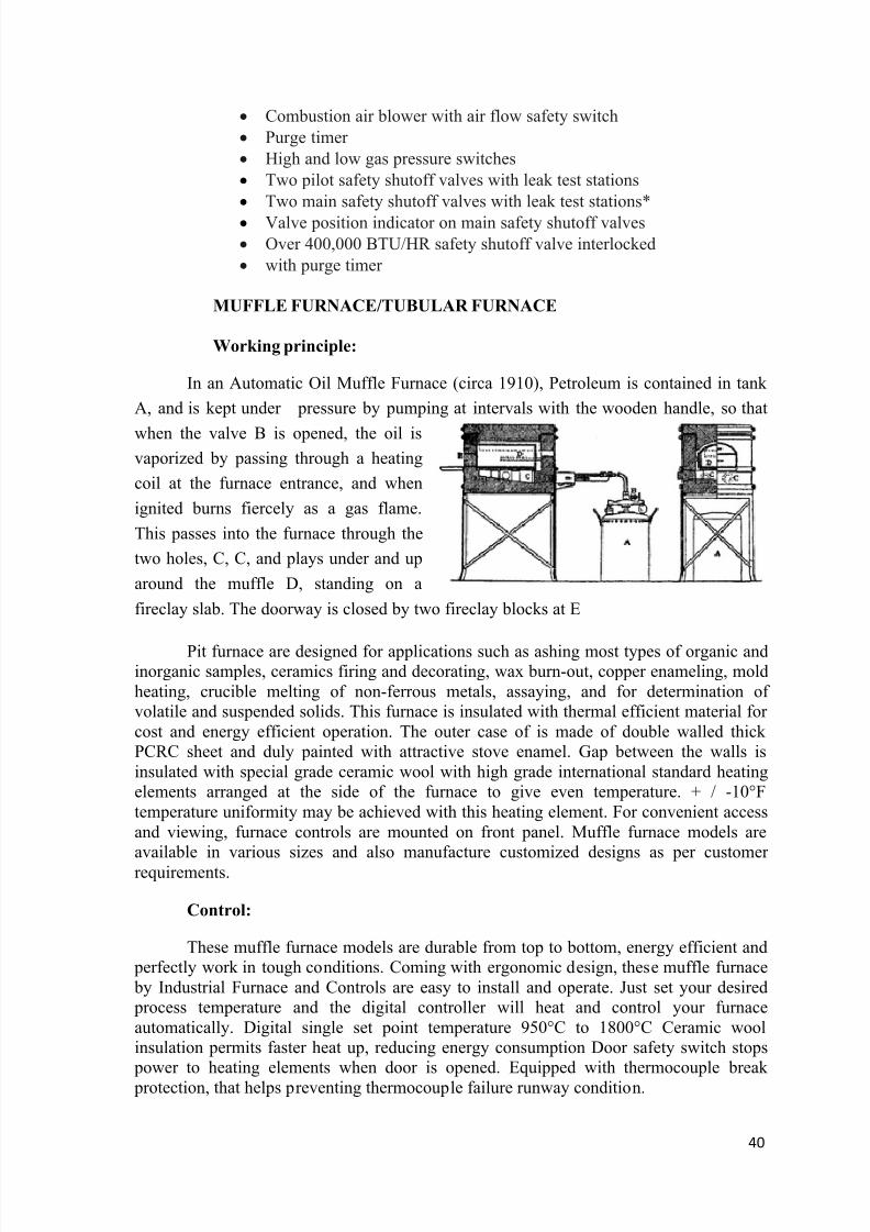
In an Automatic Oil Muffle Furnace (circa 1910), Petroleum is contained in tank
A, and is kept under pressure by pumping at intervals with the wooden handle, so that
when the valve B is opened, the oil isvaporized by passing through a heating
coil at the furnace entrance, and when
ignited burns fiercely as a gas flame.
This passes into the furnace through the
two holes, C, C, and plays under and up
around the muffle D, standing on a
fireclay slab. The doorway is closed by two fireclay blocks at E
Pit furnace are designed for applications such as ashing most types of organic andinorganic samples, ceramics firing and decorating, wax burn-out, copper enameling, moldheating, crucible melting of non-ferrous metals, assaying, and for determination ofvolatile and suspended solids. This furnace is insulated with thermal efficient material forcost and energy efficient operation. The outer case of is made of double walled thickPCRC sheet and duly painted with attractive stove enamel. Gap between the walls isinsulated with special grade ceramic wool with high grade international standard heatingelements arranged at the side of the furnace to give even temperature. + / -10°Ftemperature uniformity may be achieved with this heating element. For convenient accessand viewing, furnace controls are mounted on front panel. Muffle furnace models areavailable in various sizes and also manufacture customized designs as per customerrequirements.
Control:
These muffle furnace models are durable from top to bottom, energy efficient and perfectly work in tough conditions. Coming with ergonomic design, these muffle furnace by Industrial Furnace and Controls are easy to install and operate. Just set your desired process temperature and the digital controller will heat and control your furnaceautomatically. Digital single set point temperature 950°C to 1800°C Ceramic woolinsulation permits faster heat up, reducing energy consumption Door safety switch stops
power to heating elements when door is opened. Equipped with thermocouple break protection, that helps preventing thermocouple failure runway condition.
8/13/2019 Analysis of Grain Structure in Forging
http://slidepdf.com/reader/full/analysis-of-grain-structure-in-forging 41/55
41
IFC-1600BL BOTTOM LOADING FURNACE:
Working principle:
The single zone, high temperature, bottom loading furnace is capable of operatingat temperatures up to 1650oC in air. The furnace utilizes 1800oC molydisilicide heatingelements positioned on three sides of the internal chamber. The furnace utilizes an energyefficient insulation package consisting of graded ceramic-fiber, high temperatureinsulation. It is an ideal tool for materials annealing and sintering. Sample Size: 200x200x200mm (8"x8"x8")
BOGIE HEARTH FURNACE:
RT3 series high-temperature bogie-hearth furnace is an exclusive patents andtogether with the most advanced high-temperature. International bogie electric furnacetechnology, it has become the major product exported to the international market and
joining in international competition in India. The course of Car-Plant resistance furnacecomes to mass production on the production line, reaching the largest India production.
Working principle:
The shell is welded by steel plate and steel form, the furnace lining material usingultra-light 0.6g/cm3 energy-saving insulating refractory brick building, dissecting high-
purity aluminum blanket to insulate, expansion of home insulation powder filling, furnacemouth using quality furnace bull bricks, car surface quality-pressure high alumina bricks.Between bogie furnace and furnace body using Labyrinth refractory, but also by using thelatest technology automatically sealed agencies to reduce heat loss and improvetemperature uniformity. Furnace bottom even with the light rail vehicle are for theintegration, and users do not need to install foundation, using it only by putting it in theformed ground.
Heating elements materials are the general international OCr27Al7Mo2 resistancewire, exclusively produced Bending Upwards of 200 0C swap silk dormant silk brick, themaximum use temperature of 1440 0C. Taiwan Cr-Mn car equipped with nitrogen or 120C heat-resistant steel floor bearing silicon carbide furnace workpiece. Furnace Doormovements through rolling round in the upper and lower guide rail rolling realized,ensuring that the closure Furnace Door at the Furnace Door furnace anastomosis betweenthe seal, ensuring that the opening will not be in the process of friction injuring masonry.Furnace Door and the Taiwan-car campaign is conducted by motor through worm reducerand the chain of transmission, and equipped with electricity magnetic brakes to make anappropriate adjustment.
To improve temperature uniformity, High Temperature Bogie-hearthResistance Furnace used bogie-type multi-zone heating and Furnace Door and after thewall layout heating components, high-power High Temperature Bogie-hearth ResistanceFurnace multiple automatic temperature control counters were carried out on the multi-zone automatic temperature control heating and Furnace Door Bogie Operation.
8/13/2019 Analysis of Grain Structure in Forging
http://slidepdf.com/reader/full/analysis-of-grain-structure-in-forging 42/55
42
Control
The control system of International and temperature use the most advanced process technology curve in microcomputer automatic temperature control, ruling outmanual error. According to the user needs heat treatment technology power curve
automatically changes the size, outputting reasonable energy-saving power, making idealcurve achieves practical application of high-precision implementation in the heattreatment process. Under the heat treatment process needs, arbitrary set each heating rate(that is, heating degree), each holding temperature (that is the need to start insulation),and each holding time (that is, how long the need for the temperature insulation is).The
process can be set Ba Duan curve. Temperature is controlled in precision of ±1℃.
Uses:
It is super-energy-efficient cycle operation furnace, mainly used for high-chromium; high manganese steel castings, ductile iron, Roller, Ball, Crusher
hammerhead, wear-resistant liner quenching, annealing, timeliness and variousmechanical parts used heat treatment
HIGH TEMPERATURE/PLC FURNACE:
Working principle
Mainly used in ceramic or Refractory industries. High temperature furnaces with maximum operating temperatures of 1400°C,
1500°C , 1600°C & 1700°C. Chamber capacities of 3, 8, 15 & 35 liters. Powerful silicon carbide / MoSi2 elements located on both sides of the chamber
ensure good thermal uniformity. Silicon carbide elements can withstand the stress of everyday operation and
provide good longevity. Hardwearing refractory brick in chamber entrance and hearth provide good
resistance to abrasion. Elsewhere, lightweight ceramic fiber insulation is used to ensure good energy
efficiency and rapid heating. Vertical counter-balanced door keeps hot door insulation away from operator. Positive break door safety switch isolates chamber from power supply, when the
door is opened.
Double skinned construction allows convection air flow to cool the outer case, toconform to EN61010 safety standard.
Choice of PID controller or programmers. Applications in general industry include sintering alumina, smelt trials and
checking Al2O3 content in alumina. Applications in the ceramics industry include disintegration, testing and analysis
of cement samples, refractory porosity tests, long term high temperature tests andfiring & sintering of ceramic samples.
Applications in the semi-conductor industry include annealing silicon, siliconcarbide & nitride samples and solid state synthesis.
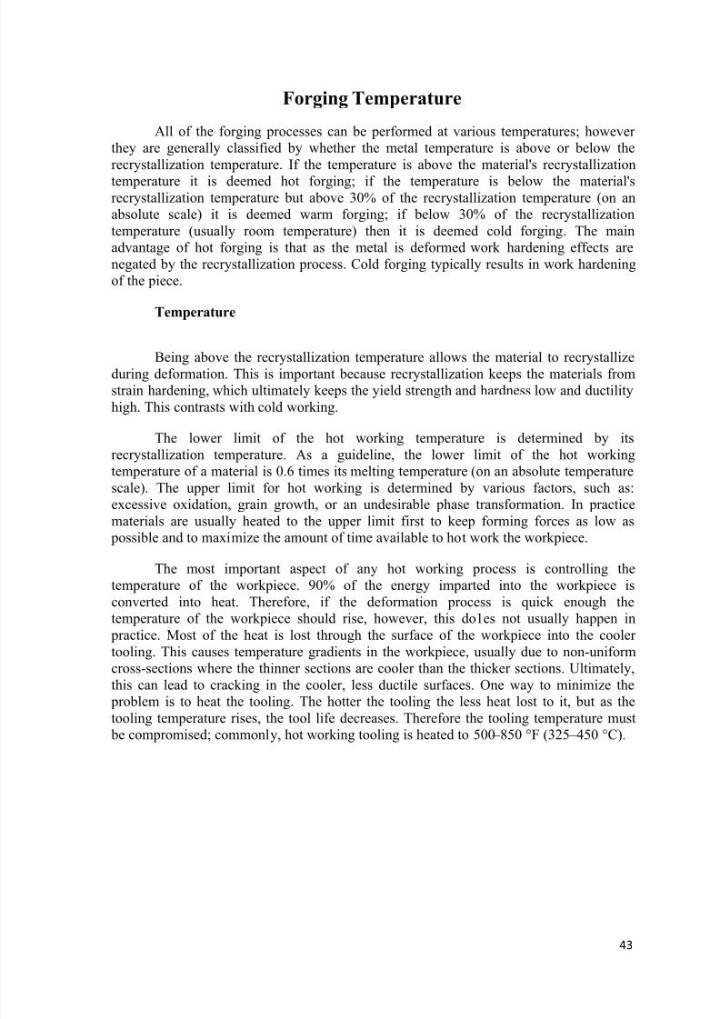
8/13/2019 Analysis of Grain Structure in Forging
http://slidepdf.com/reader/full/analysis-of-grain-structure-in-forging 43/55
43
Forging Temperature
All of the forging processes can be performed at various temperatures; howeverthey are generally classified by whether the metal temperature is above or below therecrystallization temperature. If the temperature is above the material's recrystallization
temperature it is deemed hot forging; if the temperature is below the material'srecrystallization temperature but above 30% of the recrystallization temperature (on anabsolute scale) it is deemed warm forging; if below 30% of the recrystallizationtemperature (usually room temperature) then it is deemed cold forging. The mainadvantage of hot forging is that as the metal is deformed work hardening effects arenegated by the recrystallization process. Cold forging typically results in work hardeningof the piece.
Temperature
Being above the recrystallization temperature allows the material to recrystallizeduring deformation. This is important because recrystallization keeps the materials fromstrain hardening, which ultimately keeps the yield strength and hardness low and ductilityhigh. This contrasts with cold working.
The lower limit of the hot working temperature is determined by itsrecrystallization temperature. As a guideline, the lower limit of the hot workingtemperature of a material is 0.6 times its melting temperature (on an absolute temperaturescale). The upper limit for hot working is determined by various factors, such as:excessive oxidation, grain growth, or an undesirable phase transformation. In practicematerials are usually heated to the upper limit first to keep forming forces as low as
possible and to maximize the amount of time available to hot work the workpiece.
The most important aspect of any hot working process is controlling thetemperature of the workpiece. 90% of the energy imparted into the workpiece isconverted into heat. Therefore, if the deformation process is quick enough thetemperature of the workpiece should rise, however, this do1es not usually happen in
practice. Most of the heat is lost through the surface of the workpiece into the coolertooling. This causes temperature gradients in the workpiece, usually due to non-uniformcross-sections where the thinner sections are cooler than the thicker sections. Ultimately,this can lead to cracking in the cooler, less ductile surfaces. One way to minimize the
problem is to heat the tooling. The hotter the tooling the less heat lost to it, but as the
tooling temperature rises, the tool life decreases. Therefore the tooling temperature must be compromised; commonly, hot working tooling is heated to 500 – 850 °F (325 – 450 °C).
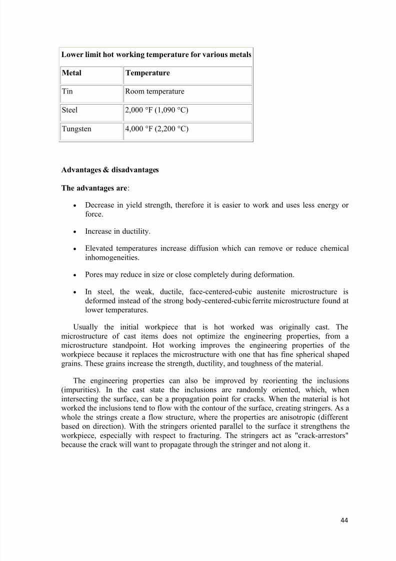
8/13/2019 Analysis of Grain Structure in Forging
http://slidepdf.com/reader/full/analysis-of-grain-structure-in-forging 44/55
44
Lower limit hot working temperature for various metals
Metal Temperature
Tin Room temperature
Steel 2,000 °F (1,090 °C)
Tungsten 4,000 °F (2,200 °C)
Advantages & disadvantages
The advantages are:
Decrease in yield strength, therefore it is easier to work and uses less energy orforce.
Increase in ductility.
Elevated temperatures increase diffusion which can remove or reduce chemicalinhomogeneities.
Pores may reduce in size or close completely during deformation.
In steel, the weak, ductile, face-centered-cubic austenite microstructure isdeformed instead of the strong body-centered-cubic ferrite microstructure found atlower temperatures.
Usually the initial workpiece that is hot worked was originally cast. Themicrostructure of cast items does not optimize the engineering properties, from amicrostructure standpoint. Hot working improves the engineering properties of theworkpiece because it replaces the microstructure with one that has fine spherical shapedgrains. These grains increase the strength, ductility, and toughness of the material.
The engineering properties can also be improved by reorienting the inclusions
(impurities). In the cast state the inclusions are randomly oriented, which, whenintersecting the surface, can be a propagation point for cracks. When the material is hotworked the inclusions tend to flow with the contour of the surface, creating stringers. As awhole the strings create a flow structure, where the properties are anisotropic (different
based on direction). With the stringers oriented parallel to the surface it strengthens theworkpiece, especially with respect to fracturing. The stringers act as "crack-arrestors"
because the crack will want to propagate through the stringer and not along it.

8/13/2019 Analysis of Grain Structure in Forging
http://slidepdf.com/reader/full/analysis-of-grain-structure-in-forging 45/55
45
The disadvantages are:
Undesirable reactions between the metal and the surrounding atmosphere (scalingor rapid oxidation of the workpiece).
Less precise tolerances due to thermal contraction and warping from unevencooling.
Grain structure may vary throughout the metal for various reasons.
Requires a heating unit of some kind such as a gas or diesel furnace or aninduction heater, which can be very expensive.
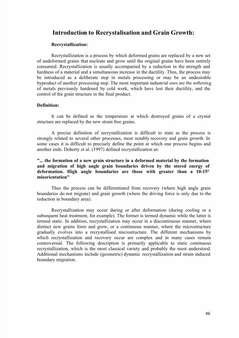
8/13/2019 Analysis of Grain Structure in Forging
http://slidepdf.com/reader/full/analysis-of-grain-structure-in-forging 46/55
46
Introduction to Recrystalisation and Grain Growth:
Recrystallization:
Recrystallization is a process by which deformed grains are replaced by a new set
of undeformed grains that nucleate and grow until the original grains have been entirelyconsumed. Recrystallization is usually accompanied by a reduction in the strength andhardness of a material and a simultaneous increase in the ductility. Thus, the process may
be introduced as a deliberate step in metals processing or may be an undesirable byproduct of another processing step. The most important industrial uses are the softeningof metals previously hardened by cold work, which have lost their ductility, and thecontrol of the grain structure in the final product.
Definition:
It can be defined as the temperature at which destroyed grains of a crystalstructure are replaced by the new strain free grains.
A precise definition of recrystallization is difficult to state as the process isstrongly related to several other processes, most notably recovery and grain growth. Insome cases it is difficult to precisely define the point at which one process begins andanother ends. Doherty et al. (1997) defined recrystallization as:
"... the formation of a new grain structure in a deformed material by the formation
and migration of high angle grain boundaries driven by the stored energy of
deformation. High angle boundaries are those with greater than a 10-15°
misorientation"
Thus the process can be differentiated from recovery (where high angle grain boundaries do not migrate) and grain growth (where the driving force is only due to thereduction in boundary area).
Recrystallization may occur during or after deformation (during cooling or asubsequent heat treatment, for example). The former is termed dynamic while the latter istermed static. In addition, recrystallization may occur in a discontinuous manner, wheredistinct new grains form and grow, or a continuous manner, where the microstructuregradually evolves into a recrystallised microstructure. The different mechanisms by
which recrystallization and recovery occur are complex and in many cases remaincontroversial. The following description is primarily applicable to static continuousrecrystallization, which is the most classical variety and probably the most understood.Additional mechanisms include (geometric) dynamic recrystallization and strain induced
boundary migration.
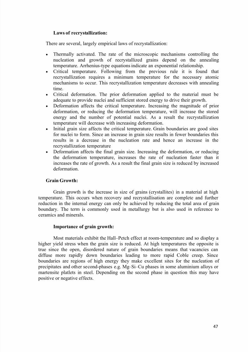
8/13/2019 Analysis of Grain Structure in Forging
http://slidepdf.com/reader/full/analysis-of-grain-structure-in-forging 47/55
47
Laws of recrystallization:
There are several, largely empirical laws of recrystallization:
Thermally activated. The rate of the microscopic mechanisms controlling the
nucleation and growth of recrystallized grains depend on the annealingtemperature. Arrhenius-type equations indicate an exponential relationship. Critical temperature. Following from the previous rule it is found that
recrystallization requires a minimum temperature for the necessary atomicmechanisms to occur. This recrystallization temperature decreases with annealingtime.
Critical deformation. The prior deformation applied to the material must beadequate to provide nuclei and sufficient stored energy to drive their growth.
Deformation affects the critical temperature. Increasing the magnitude of priordeformation, or reducing the deformation temperature, will increase the storedenergy and the number of potential nuclei. As a result the recrystallization
temperature will decrease with increasing deformation. Initial grain size affects the critical temperature. Grain boundaries are good sites
for nuclei to form. Since an increase in grain size results in fewer boundaries thisresults in a decrease in the nucleation rate and hence an increase in therecrystallization temperature
Deformation affects the final grain size. Increasing the deformation, or reducingthe deformation temperature, increases the rate of nucleation faster than itincreases the rate of growth. As a result the final grain size is reduced by increaseddeformation.
Grain Growth:
Grain growth is the increase in size of grains (crystallites) in a material at hightemperature. This occurs when recovery and recrystallisation are complete and furtherreduction in the internal energy can only be achieved by reducing the total area of grain
boundary. The term is commonly used in metallurgy but is also used in reference toceramics and minerals.
Importance of grain growth:
Most materials exhibit the Hall – Petch effect at room-temperature and so display ahigher yield stress when the grain size is reduced. At high temperatures the opposite istrue since the open, disordered nature of grain boundaries means that vacancies candiffuse more rapidly down boundaries leading to more rapid Coble creep. Since
boundaries are regions of high energy they make excellent sites for the nucleation of precipitates and other second-phases e.g. Mg – Si – Cu phases in some aluminium alloys ormartensite platlets in steel. Depending on the second phase in question this may have
positive or negative effects.
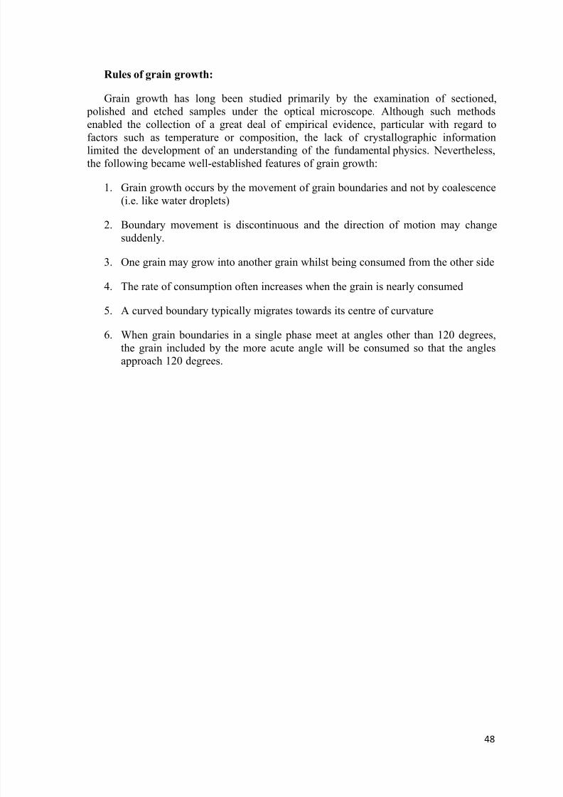
8/13/2019 Analysis of Grain Structure in Forging
http://slidepdf.com/reader/full/analysis-of-grain-structure-in-forging 48/55
48
Rules of grain growth:
Grain growth has long been studied primarily by the examination of sectioned, polished and etched samples under the optical microscope. Although such methodsenabled the collection of a great deal of empirical evidence, particular with regard to
factors such as temperature or composition, the lack of crystallographic informationlimited the development of an understanding of the fundamental physics. Nevertheless,the following became well-established features of grain growth:
1. Grain growth occurs by the movement of grain boundaries and not by coalescence(i.e. like water droplets)
2. Boundary movement is discontinuous and the direction of motion may changesuddenly.
3. One grain may grow into another grain whilst being consumed from the other side
4. The rate of consumption often increases when the grain is nearly consumed
5. A curved boundary typically migrates towards its centre of curvature
6. When grain boundaries in a single phase meet at angles other than 120 degrees,the grain included by the more acute angle will be consumed so that the anglesapproach 120 degrees.
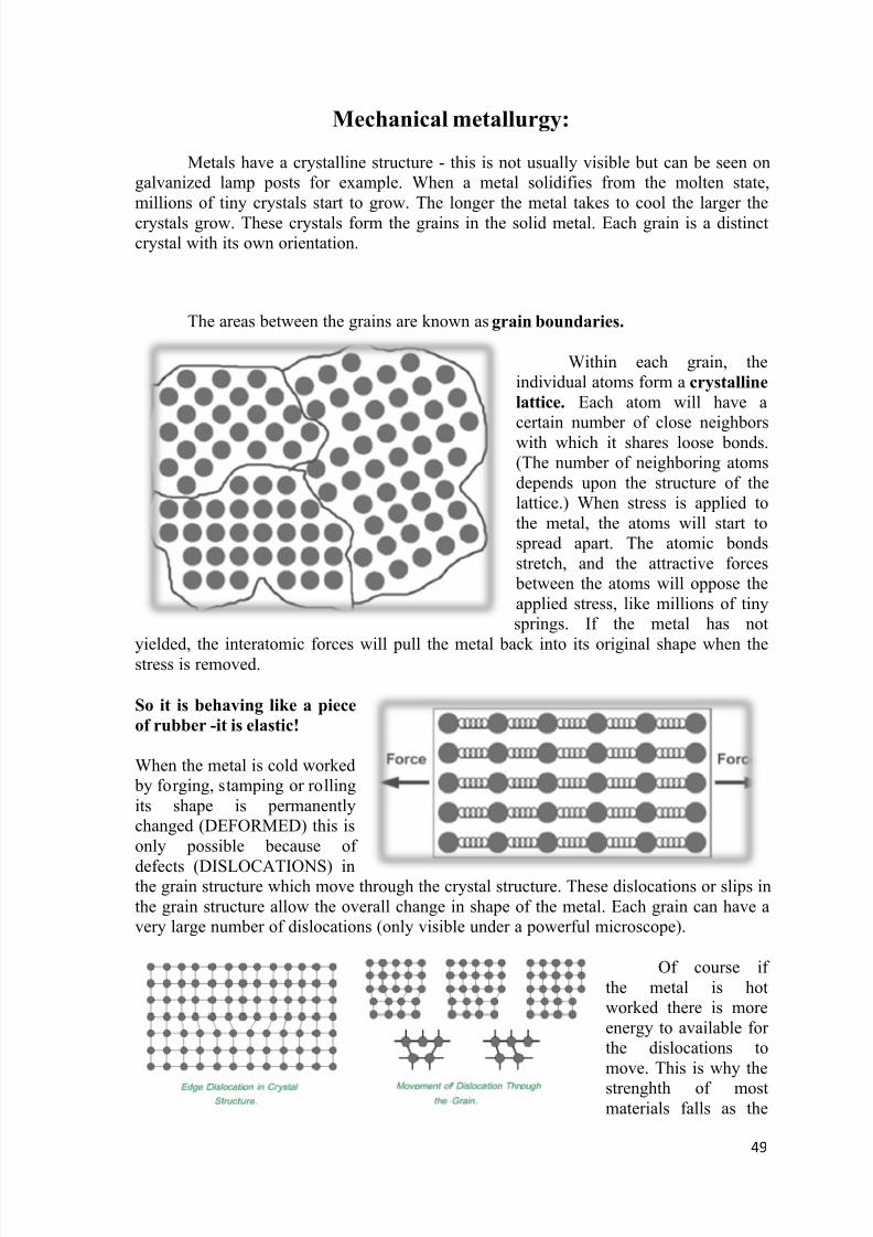
8/13/2019 Analysis of Grain Structure in Forging
http://slidepdf.com/reader/full/analysis-of-grain-structure-in-forging 49/55
49
Mechanical metallurgy:
Metals have a crystalline structure - this is not usually visible but can be seen ongalvanized lamp posts for example. When a metal solidifies from the molten state,millions of tiny crystals start to grow. The longer the metal takes to cool the larger the
crystals grow. These crystals form the grains in the solid metal. Each grain is a distinctcrystal with its own orientation.
The areas between the grains are known as grain boundaries.
Within each grain, theindividual atoms form a crystalline
lattice. Each atom will have acertain number of close neighborswith which it shares loose bonds.(The number of neighboring atomsdepends upon the structure of thelattice.) When stress is applied tothe metal, the atoms will start tospread apart. The atomic bondsstretch, and the attractive forces
between the atoms will oppose theapplied stress, like millions of tinysprings. If the metal has not
yielded, the interatomic forces will pull the metal back into its original shape when thestress is removed.
So it is behaving like a piece
of rubber -it is elastic!
When the metal is cold worked by forging, stamping or rollingits shape is permanentlychanged (DEFORMED) this isonly possible because of
defects (DISLOCATIONS) inthe grain structure which move through the crystal structure. These dislocations or slips inthe grain structure allow the overall change in shape of the metal. Each grain can have avery large number of dislocations (only visible under a powerful microscope).
Of course ifthe metal is hotworked there is moreenergy to available forthe dislocations tomove. This is why the
strenghth of mostmaterials falls as the
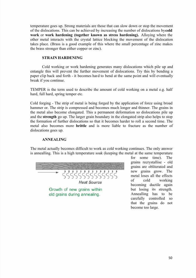
8/13/2019 Analysis of Grain Structure in Forging
http://slidepdf.com/reader/full/analysis-of-grain-structure-in-forging 50/55
50
temperature goes up. Strong materials are those that can slow down or stop the movementof the dislocations. This can be achieved by increasing the number of dislocations by cold
work or work hardening (together known as stress hardening). Alloying where theother metal interacts with the crystal lattice blocking the movement of the dislocationtakes place. (Brass is a good example of this where the small percentage of zinc makes
the brass stronger than either copper or zinc).
STRAIN HARDENING
Cold working or work hardening generates many dislocations which pile up andentangle this will prevent the further movement of dislocations. Try this by bending a
paper clip back and forth - it becomes hard to bend at the same point and will eventually break if you continue.
TEMPER is the term used to describe the amount of cold working on a metal e.g. halfhard, full hard, spring temper etc.
Cold forging - The strip of metal is being forged by the application of force using broadhammer or. The strip is compressed and becomes much longer and thinner. The grains inthe metal also become elongated. This a permanent deformation so dislocations pile upand the strength go up. The larger grain boundary in the elongated strip also helps to stopthe formation of further dislocations so that it becomes harder to roll a second time. Themetal also becomes more brittle and is more liable to fracture as the number ofdislocations goes up.
ANNEALING
The metal actually becomes difficult to work as cold working continues. The only answeris annealling. This is a high temperature soak (keeping the metal at the same temperature
for some time). Thegrains recrystallise - oldgrains are obliterated andnew grains grow. Themetal loses all the effectsof cold working
becoming ductile again but losing its strength.
Annealling has to becarefully controlled sothat the grains do not
become too large.
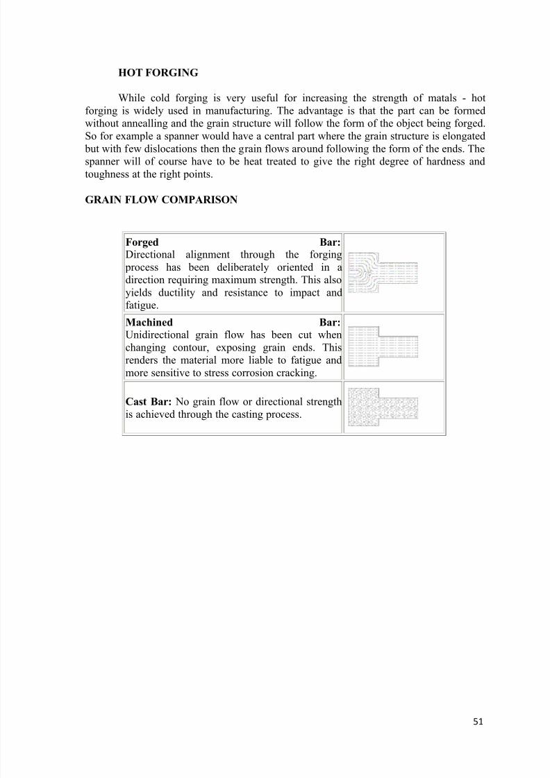
8/13/2019 Analysis of Grain Structure in Forging
http://slidepdf.com/reader/full/analysis-of-grain-structure-in-forging 51/55
51
HOT FORGING
While cold forging is very useful for increasing the strength of matals - hotforging is widely used in manufacturing. The advantage is that the part can be formedwithout annealling and the grain structure will follow the form of the object being forged.
So for example a spanner would have a central part where the grain structure is elongated but with few dislocations then the grain flows around following the form of the ends. Thespanner will of course have to be heat treated to give the right degree of hardness andtoughness at the right points.
GRAIN FLOW COMPARISON
Forged Bar: Directional alignment through the forging
process has been deliberately oriented in adirection requiring maximum strength. This alsoyields ductility and resistance to impact andfatigue.
Machined Bar: Unidirectional grain flow has been cut whenchanging contour, exposing grain ends. Thisrenders the material more liable to fatigue andmore sensitive to stress corrosion cracking.
Cast Bar: No grain flow or directional strengthis achieved through the casting process.
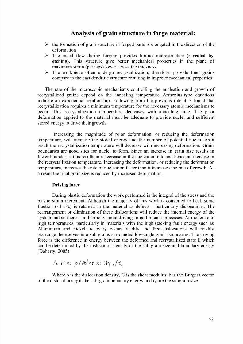
8/13/2019 Analysis of Grain Structure in Forging
http://slidepdf.com/reader/full/analysis-of-grain-structure-in-forging 52/55
52
Analysis of grain structure in forge material:
the formation of grain structure in forged parts is elongated in the direction of thedeformation
The metal flow during forging provides fibrous microstructure (revealed by
etching). This structure give better mechanical properties in the plane ofmaximum strain (perhaps) lower across the thickness.
The workpiece often undergo recrystallization, therefore, provide finer grainscompare to the cast dendritic structure resulting in improve mechanical properties.
The rate of the microscopic mechanisms controlling the nucleation and growth ofrecrystallized grains depend on the annealing temperature. Arrhenius-type equationsindicate an exponential relationship. Following from the previous rule it is found thatrecrystallization requires a minimum temperature for the necessary atomic mechanisms tooccur. This recrystallization temperature decreases with annealing time. The priordeformation applied to the material must be adequate to provide nuclei and sufficientstored energy to drive their growth.
Increasing the magnitude of prior deformation, or reducing the deformationtemperature, will increase the stored energy and the number of potential nuclei. As aresult the recrystallization temperature will decrease with increasing deformation. Grain
boundaries are good sites for nuclei to form. Since an increase in grain size results infewer boundaries this results in a decrease in the nucleation rate and hence an increase inthe recrystallization temperature. Increasing the deformation, or reducing the deformationtemperature, increases the rate of nucleation faster than it increases the rate of growth. Asa result the final grain size is reduced by increased deformation.
Driving force
During plastic deformation the work performed is the integral of the stress and the plastic strain increment. Although the majority of this work is converted to heat, somefraction (~1-5%) is retained in the material as defects - particularly dislocations. Therearrangement or elimination of these dislocations will reduce the internal energy of thesystem and so there is a thermodynamic driving force for such processes. At moderate tohigh temperatures, particularly in materials with the high stacking fault energy such asAluminium and nickel, recovery occurs readily and free dislocations will readilyrearrange themselves into sub grains surrounded low-angle grain boundaries. The driving
force is the difference in energy between the deformed and recrystallized state E whichcan be determined by the dislocation density or the sub grain size and boundary energy(Doherty, 2005):
Where ρ is the dislocation density, G is the shear modulus, b is the Burgers vectorof the dislocations, γ is the sub-grain boundary energy and ds are the subgrain size.
8/13/2019 Analysis of Grain Structure in Forging
http://slidepdf.com/reader/full/analysis-of-grain-structure-in-forging 53/55
53
Data Analysis
Changing in grain structure means the micro-structural change of any material.
When the grain structure change the material started to being deformed. When a material
solidified from molten state millions of tiny crystals start to grow. The longer the metaltakes to cool the larger the crystal grow. Then the crystals formed grains in a solid metal.
Each grain is a decent crystal with its own orientation. The area between the grains are
called grain boundary.
From the analysis, it can be inferred that mechanical properties depends largely
upon the various form of forging operations and forging temperature.
In hot working process when the materials heated above recrystallization
temperature the material comes in plastic stage, Metal is deform and work hardening
effects are neglected by the recrystallization process. The internal stresses of grains
started to release and the most notable recovery and grain growth takes place. In the
process of recovery high angle grain boundary do not migrate.
In the case of cold forging, the metal is not heated. Here when we hammered the
metal, the grain boundaries are breaks and then the grains are goes to arrange. By this
arrangement, the dislocation between them is reduced. After that, the newly arranged
grains are formed various shaped metals. Thus the work hardening effect also takes place.
By this process, a broad knowledge got about various forging processes and its
internal changes in specified temperature for specified processes.
8/13/2019 Analysis of Grain Structure in Forging
http://slidepdf.com/reader/full/analysis-of-grain-structure-in-forging 54/55
54
Conclusion
Under engineering shops and foundry of Visakhapatnam Steel Plant, the project
work on “ANALYSIS OF GRAIN STRUCTURE IN FORGING” is very fruitful for
gaining knowledge in several processes, crystallite and grain growth during thedeformation processes of forging.
Depending upon the properties and the applications that may be required for any
design purpose, a suitable form of forging should be adopted in suitable temperature.
Also it is understood that how forging process changes the microstructure of any material.
It is also seen that by adopting a proper hardening process cycle the properties of
hardness can be achieved in forged material simultaneously we understood that tempering
process follows hardening process so as to relieve the internal stress induced byhardening and to give the material its required toughness by making it more shock
resistant which is required property for forged material.
During the project, it is also known to us about the various departments of
Visakhapatnam steel Plant, which helped us not only the completion of the project but
also get a partial knowledge about this industry
8/13/2019 Analysis of Grain Structure in Forging
http://slidepdf.com/reader/full/analysis-of-grain-structure-in-forging 55/55
Bibliography
www.wikipedia.com
www.nptel.iitm.ac.in
Manufacturing Technology by P.N.Rao
Gate material of brilliant tutorial
www.me.iitb.ac.in
www.tech.plym.ac.uk
Degarmo, E. Paul; Black, J. T.; Kohser, Ronald A. (2003), Materials andProcesses in Manufacturing (9th ed.), Wiley
Workshop technology by HAZRA CHOUDARY.
www.the-warren.org