Embed Size (px)
Citation preview
International Journal of Scientific & Engineering Research Volume 4, Issue 5, May-2013 ISSN 2229-5518
IJSER © 2013
http://www.ijser.org
Analysis of Geotextile Reinforced Embankment on
Difficult Subsoil Condition Jigisha M. Vashi, Atul K. Desai, Chandresh H. Solanki
Abstract—The behavior of geotextile reinforced embankment (GRE) on difficult subsoil condition was analyzed in this study. The embankment were
backfilled with flyash(80%) & clay(20%) soil and the safety factors obtained from general limit equilibrium and finite element analysis. To compare with
the analysis results from the GRE, variable geotextile stiffness of 50 to 2000 kN/m were taken as reinforcement and series of finite element method (FEM)
analyses were carried out with GEO5-FEM software. The FEM analysis results showed that failure plane of stress counter for different model with variable
stiffness was more or less consistent with each other. Modeling results such as the maximum horizontal and vertical displacements in GRE have a good
agreement with the measured data by other researchers. In addition, maximum horizontal displacements and vertical settlement have not noteworthy influ-
ence while decreasing vertical spacing of 0.5m to 0.4 m for geotextile. Based on this study, it could be concluded that beyond 500 kN/m strength of geotex-
tile reinforcement is not effective to reduce the displacement of the embankment face and/or the deformation of the backfill soil even if the mobilized tensile
stress after construction is very small.
Index Terms— deformation behavior, difficult subsoil, flyash & clay backfill, geotextile, numerical analysis, reinforced earth embankment
—————————— ——————————
1 INTRODUCTION
HE limited equilibrium technique has been used for the design and the analysis of reinforced structure since the reinforced earth was commercially used at the first time. In the limited
equilibrium design, the force applied to the top of the wall is used to calculate the horizontal pressure, which is resisted by the reinforce-ment. Although these forces are easily applied to the limited equilib-rium design, they cannot be simply incorporated to the prediction of deformation. The finite element technique was applied to analyze the behavior of the reinforced earth in the middle of 70’s.
FEM has been used for the study of numerous parameters and for the analysis of the GRE. In the research for the GRE, FEM has been mainly applied to predict the reinforcing strains and the deformation of the embankment [1], [2], [3], [4]. FEM has been also applied to analyze the parameters such as the length [5], [2], the strength, the spacing, the stiffness, and the arrangement of the reinforcement [6], facing material and facing construction [7], [8], compaction stress and friction at the interface between the soil and the reinforcement and the relative motion [3]. Silva and Pameria [9] and Shukla [10], suggested that by putting berm in the embankment can increase the factor of safety of reinforced structure.
In present study the geotextile reinforced earth embankment ge-ometry is prepared in such a way to incorporating the specified safe embankment slope of 58° & 64° with berm at 4 m height in rein-forced earth embankment. Geotextile vertical spacing of 0.4 & 0.5 m with a variable stiffness of 50 to 2000 kN/m (Here the market avail-ability has been a constraint for adopting) was followed.
GEO5-FEM analysis was carried out for flooded condition. The main trigger mechanism of embankment failure on soft soil is related to rainwater infiltration in monsoon season when flooding occur. The precipitation water infiltrates into the weathered clayey slope debris and seeps via stabilized clay down to the boundary to desiccated clay. Umravia et al [11] observed failure of reinforced earth wall, due to precipitation of flood water in to foundation. Therefore, FEM analysis was carried out considering worst condition so the model was analyzed for flooded condition (F.L effect at G.L) only. The typi-cal proposed geometrical layout of GRE with berm developed by trials is shown in Figure 1. In this study, horizontal and vertical stresses and horizontal and shear displacements working on the em-bankment face with geotextile reinforcement at the backfill will be compared and analyzed by GEO5-FEM software [12].
2 GEOMETRY AND MODELING In the present investigation, typical model with 8 m high embank-ment, a crest width of 20 m and having slope angles of 58° at base and adopting berm at 4 m height considering slope angle of 64° was implanted. The embankment is placed over a 2 m thick embankment foundation overlying a relatively soft layer of 5 m thickness. A nom-inal height of 8 m is considered, based on commonly adopted indus-try practice of vertical clearance required for flyover openings, which is 6 m as per [13].
The embankment was reinforced by layers of geotextile having variable length from top to bottom, covering whole width of em-bankment. The vertical spacing of geotextile is varied from 0.5 m and 0.4 m. The finite element mesh used in these analyses involved 2037 elements with 6-nodes. Figure 1 shows the assumed boundary conditions and distinguished layers according to the representative materials.
A series of finite element analyses was performed on embank-ments of the type shown in Figure 1, constructed on a soft clayey desiccated foundation, for a variety of geotextile stiffness. The anal-yses were performed to obtain estimates of embankment deformation
T
————————————————
Jigisha M. Vashi is currently pursuing Ph.D degree program in Soil Me-chanics & Foundation Engineering Section in S V National Institute of Technology, Surat, Gujarat, India, PH-09879444739. E-mail: [email protected]
Atul K. Desai, and Chandresh H. Solanki is Professor in Soil Mechanics & Foundation Engineering Section in S V National Institute of Technology, Surat, Gujarat, India, PH-09327433390. E-mail: [email protected]
41
IJSER

International Journal of Scientific & Engineering Research Volume 4, Issue 5, May-2013 ISSN 2229-5518
IJSER © 2013
http://www.ijser.org
for embankments reinforced with geotextiles ranging in "moduli" from 50 kN/m to 2000 kN/m. Also it was assumed that each layer of geotextile has same tensile strength/stiffness & placed horizontally. Soil parameters of the backfill are determined by lab test by [14], Table 1. Parameters of the foundation are determined by feedback analysis based on the measured data from the literature. In this study, the analytical modeling of earth embankment with geotextile rein-forcement is performed using the GEO5-FEM software.
Fig. 1. Geometry of models
Fig. 2. Various section of earth embankment for analysis
3 RESULTS AND DISSCUSSIONS The analysis of FEM embankment model with distance of 12 m was selected from side boundary to embankment toe. To study the behav-ior of reinforced embankment on soft soil FEM analysis was carried out. Figure 2 shows the various sections A-A, B-B, C-C. D-D, E-E, and F-F of the geotextile reinforced earth embankment at which the measured vertical settlement and horizontal displacement were com-puted by GEO5-FEM.
Typical maximum critical vertical settlement and horizontal dis-placement section of reinforced embankment for stiffness of 200 kN/m at Sv = 0.5 m are shown in Figures 4 and 5 respectively and tress contours for the same are shown in Figure 3.
The maximum vertical settlement ranges observed for all variable stiffness of 50 to 2000 kN/m at section A-A, B-B and D-D of the reinforced embankment are 0.38 % to 1.78 %, 0.25 % to 1.27 % and
(-) 0.02 % to 0.26 % of embankment height respectively. Here at section D-D the negative sign indicates the small heave is observed at toe of the embankment. The maximum vertical settlement for the unreinforced soil mass is about 2.4 % to 4 % of the embankment height [15], [16], [17]. This means that vertical settlement of the backfill is considerably restrained by the lower stiffness and vertical spacing of the reinforcement material and by the interaction between the soil and the reinforcement. The higher geotextile stiffness and spacing have not more influence on decreasing vertical settlement. This is due to the very stiff embankment body as high modulus of fill.
Fig. 3. Typical vertical settlement and horizontal displacement contour of reinforced embankment at various sections for 200 kN/m stiffness at Sv =
TABLE 1 UNITS FOR MAGENTIC PROPERTIES
42
IJSER
International Journal of Scientific & Engineering Research Volume 4, Issue 5, May-2013 ISSN 2229-5518
IJSER © 2013
http://www.ijser.org
0.5 m
These analysis results are in agreement with the analysis reported
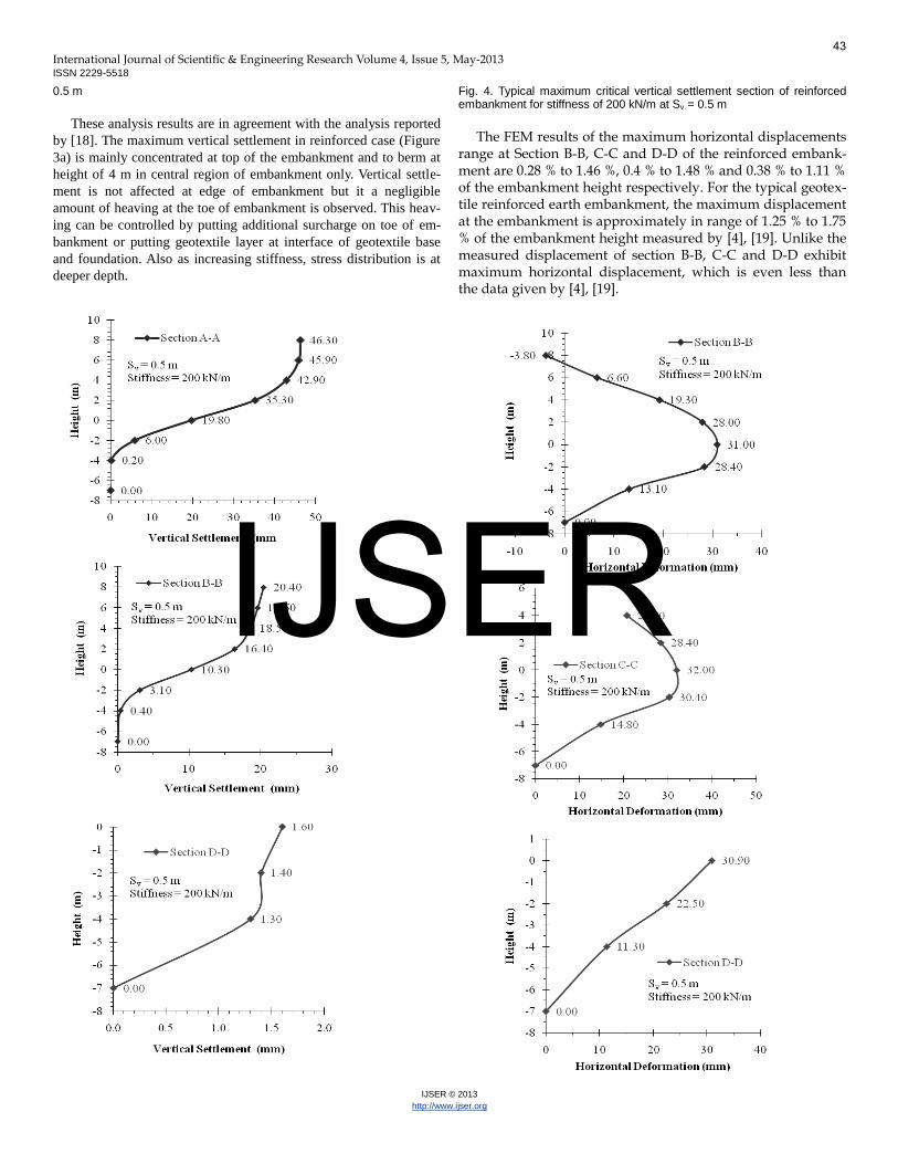
by [18]. The maximum vertical settlement in reinforced case (Figure 3a) is mainly concentrated at top of the embankment and to berm at height of 4 m in central region of embankment only. Vertical settle-ment is not affected at edge of embankment but it a negligible amount of heaving at the toe of embankment is observed. This heav-ing can be controlled by putting additional surcharge on toe of em-bankment or putting geotextile layer at interface of geotextile base and foundation. Also as increasing stiffness, stress distribution is at deeper depth.
Fig. 4. Typical maximum critical vertical settlement section of reinforced embankment for stiffness of 200 kN/m at Sv = 0.5 m
The FEM results of the maximum horizontal displacements
range at Section B-B, C-C and D-D of the reinforced embank-ment are 0.28 % to 1.46 %, 0.4 % to 1.48 % and 0.38 % to 1.11 % of the embankment height respectively. For the typical geotex-tile reinforced earth embankment, the maximum displacement at the embankment is approximately in range of 1.25 % to 1.75 % of the embankment height measured by [4], [19]. Unlike the measured displacement of section B-B, C-C and D-D exhibit maximum horizontal displacement, which is even less than the data given by [4], [19].
43
IJSER
International Journal of Scientific & Engineering Research Volume 4, Issue 5, May-2013 ISSN 2229-5518
IJSER © 2013
http://www.ijser.org
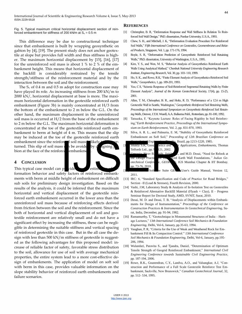
Fig. 5. Typical maximum critical horizontal displacement section of rein-forced embankment for stiffness of 200 kN/m at Sv = 0.5 m
This difference may be due to constructional technique
since that embankment is built by wrapping geosynthetic on gabion by [4], [19]. The present study does not anchor geotex-tile at slope but provides full width and thus stiffness is high-er. The maximum horizontal displacement by [15], [16], [17] for the unreinforced soil mass is about 1 % to 2 % of the em-bankment height. This means that horizontal displacement of the backfill is considerably restrained by the tensile strength/stiffness of the reinforcement material and by the interaction between the soil and the reinforcement.
The Sv of 0.4 m and 0.5 m adopt for construction ease may have played its role. As increasing stiffness from 200 kN/m to 2000 kN/, horizontal displacement at base is more. The maxi-mum horizontal deformation in the geotextile reinforced earth embankment (Figure 3b) is mainly concentrated at H/3 from the bottom of the embankment to 2 m below the G.L. On the other hand, the maximum displacement in the unreinforced soil mass is occurred at H/2 from the base of the embankment to 2 m below the G.L. The maximum horizontal deformation is concentrated at the toe of the geotextile reinforced earth em-bankment to berm at height of 4 m. This means that the slip may be induced at the toe of the geotextile reinforced earth embankment since the reinforced soil mass is likely to be over-turned. This slip of soil mass can be avoided by designing ga-bion at the face of the reinforced embankment.
4 CONCLUSION This typical case model can provide a quick estimation of de-
formation behavior and safety factors of reinforced embank-
ments with berm at middle height of embankment on difficult
sub soils for preliminary design investigation. Based on the
results of the analysis, it could be inferred that the maximum
horizontal and vertical displacement of the geotextile rein-
forced earth embankment occurred in the lower area than the
unreinforced soil mass because of reinforcing effects derived
from friction between the soil and the reinforcement. Since the
both of horizontal and vertical displacement of soil and geo-
textile reinforcement are relatively small and do not have a
significant effect by increasing the stiffness, these can be negli-
gible in determining the suitable stiffness and vertical spacing
of reinforced geotextile in this case. But in the all case the de-
sign with less than 500 kN/m stiffness of geotextile is suggest-
ed as the following advantages for this proposed model: in-
crease of reliable factor of safety, favorable stress distribution
to the soil, allowance for use of soil with average mechanical
properties, the entire system lead to a more cost-effective de-
sign of embankments. The application of model on soft soil
with berm in this case, provides valuable information on the
slope stability behavior of reinforced earth embankments and
failure scenarios.
REFERENCES
[1] Christopher, B. R, “Deformation Response and Wall Stiffness In Relation To Rein-
forced Soil Wall Design,” PhD. dissertation, Purdue University, U.S.A., 1993.
[2] Chew, S. H., and Mitchell, J. K, “Deformation Evaluation Procedure For Reinforced
Soil Walls,” Fifth International Conference on Geotextiles, Geomembranes and Relat-
ed Products, Singapore, Vol. 1, pp. 171-176, 1994.
[3] Boyle, S. R, “Deformation Prediction of Geosynthetic Reinforced Soil Retaining
Walls,” PhD. dissertation, University of Washington, U.S.A., 1995.
[4] Kim, Y. S., and Won, M. S, “Behavior Analysis of Geosynthetics Reinforced Earth
Walls Using Analytical Method,” Chonbuk National University Engineering Research
Institute, Engineering Research, Vol. 30, pp. 103- 110, 1999.
[5] Ho, S. K., and Rowe, R.K, “Finite Element Analysis of Geosynthetics-Reinforced Soil
Walls,” Geosynthetics, 1, pp. 189-201, 1993.
[6] Yoo, C.S, “Seismic Response of Soil-Reinforced Segmental Retaining Walls by Finite
Element Analysis”, Journal of the Korean Geotechnical Society, 17(4), pp. 15-25,
2001.
[7] Allen, T. M., Chrisopher, B. R., and Holtz, R. D, “Performance of a 12.6 m High
Geotextile Wall in Seattle, Washington,” Geosynthetic-Reinforced Soil Retaining Walls,
Proceedings of the International Symposium on Geosynthetic-Reinforced Soil Retain-
ing Walls, Denver, J.T.H. Wuedl, A.A. Balkema Publ., Rotterdam, pp. 81-100, 1992.
[8] Tatsuoka, F, “Keynote Lecture: Roles of Facing Rigidity In Soil Reinforc-
ing,”Earth Reinforcement Practice, Proceedings of the International Sympo-
sium on Earth Reinforcement, Vol. 2, pp. 831-870, 1993.
[9] Silva, A. R. L., and Palmeria, E. M, “Stability of Geosynthetic Reinforced
Embankment on Soft Soil,” Proceeding of 12th Brazilian Conference on
Geotechnical Engineering, Brasilia, Brazil, pp.1213-1220, 1985. [10] Shukla S.K, Geosynthetics and Their Applications, Embankments, Thomas
Telfords Ltd., pp. 96-121, 2002. [11] Umravia, Nirav B., Vashi, Jigisha M., and M.D. Desai, “Need for Relook at
the Design Practice for Reinforced Earth Wall Foundations,” Indian Ge-otechnical Conference, GEOtrendz, IGS Mumbai Chapter & IIT Bombay. pp. 73-76, 2010.
[12] Geotechnical Software Suite GEO5- User's Guide Manual, Version 12, 2011.
[13] IRC: 6, “Standard Specification and Code of Practice for Road Bridges,”
Section –II (Load & Stresses), Fourth Revision, 2000. [14] Vashi, J.M, Laboratory Study & Analysis of In-Isolation Test on Geotextiles
& Reinforced Alternative Backfill Material (Flyash + Clay), II – Progress Seminar Report for Doctoral Study, AMD, SVNIT, Surat, 2010.
[15] Desai, M. D. and Desai, T. B, “Analysis of Displacements within Embank-ments for Design of Instrumentation,” Proceedings of the Conference on Construction Practices & Instrumentation In Geotechnical Engineering, Su-rat, India, December, pp. 91-94, 1982.
[16] Ramamurthy, T, “Geotechnique in Monumental Structures of India – Harit-age Lectures,” 13th International Conference Soil Mechanics & Foundation Engineering, Delhi, Vol-6, January, pp.35-63, 1994.
[17] Vaughan, P. R, “Criteria for the Use of Weak and Weathered Rock for Em-bankment Fill & Its Compaction Control.” 13th International Conference Soil Mechanics & Foundation Engineering, Delhi, Vol-6, January, pp.195-206, 1994.
[18] Wulandari, Paravita S., and Tjandra, Daniel, “Determination of Optimum Tensile Strength of Geogrid Reinforced Embankment,” International Civil Engineering Conference towards Sustainable Civil Engineering Practice, pp. 187-194, 2006.
[19] Rowe, R.K., Gnanendran, C.Y., Landva, A.O., and Valsangkar, A.J, “Con-struction and Performance of a Full Scale Geotextile Reinforce Test Em-bankment, Sackville, New Brunswick,” Canadian Geotechnical Journal, 32, pp. 512- 534, 1995.
44
IJSER


![24-04_1200-1330_Ejercicio Geotextile Reinforced Embankment With Consolidation [PLAXIS]](https://img.pdfslide.us/doc/110x75/552f96734a7959b4388b461e/24-041200-1330ejercicio-geotextile-reinforced-embankment-with-consolidation-plaxis.jpg)