Embed Size (px)
Citation preview

INTERNATIONAL JOURNAL OF PROFESSIONAL ENGINEERING STUDIES Volume VIII /Issue 3 / MAR 2017
IJPRES
ABSTRACT:
When a structure is subjected to earthquake, it
responds by vibrating. An earthquake force can be
resolved into three mutually perpendicular directions-the
two horizontal directions (x and y) and the vertical
direction (z). This motion causes the structure to vibrate
or shake in all three directions; the predominant direction
of shaking is horizontal. It is very essential to consider the
effects of lateral loads induced from wind and
earthquakes in the analysis of reinforced concrete
structures, especially for high-rise buildings. The basic
intent of analysis for earthquake resistant structures is
that buildings should be able to resist minor earthquakes
without damage. It resists moderate earthquakes without
structural damage but sometimes non-structural damage
will resist major earthquakes without collapse the major
structure. To avoid collapse during a major earthquake,
members must be ductile enough to absorb and dissipate
energy by post-elastic deformation. Redundancy in the
structural system permits redistribution of internal forces
in the failure of key elements. When the primary element
or system yields or fails, the lateral force certainly
redistributed to a secondary system to prevent progressive
failure. The objectives of the present work is to study the
behavior of a multi storied R C building irregular in plan
subjected to earth quake load by adopting Response
spectrum analysis.
The present study is limited to reinforced
concrete (RC) multi-storied commercial building with
FOUR different zones II, III, IV & V .The analysis is
Carried out the help of FEM software’s ETabs. The
building model in the study has twenty storey’s with
constant storey height of 3m. FOUR models are used to
analyze with different bay lengths and the number of
Bays and the bay-width along two horizontal directions
are kept constant in each model for convenience. Different
values of SEISMIC ZONE FACTOR are taken and their
corresponding effects are interpreted in the results.
I.INTRODUCTION:
Dynamic actions are caused on buildings by
both wind and earthquakes. But, design for wind
forces and for earthquake effects are distinctly
different. The intuitive philosophy of structural
design uses force as the basis, which is consistent in
wind design, wherein the building is subjected to a
pressure on its exposed surface area; this is force-
type loading. However, in earthquake design, the
building is subjected to random motion of the ground
at its base, which induces inertia forces in the
building that in turn cause stresses; this is
displacement-type loading. Another way of
expressing this difference is through the load-
deformation curve of the building – the demand on
the building is force(i.e., vertical axis) in force-type
loading imposed by wind pressure, and
displacement(i.e., horizontal axis) in displacement-
type loading imposed by earthquake shaking. Wind
force on the building has a non-zero mean component
superposed with a relatively small oscillating
ANALYSIS OF G+20 RC BUILDING IN DIFFERENT ZONES USING ETABS NARLA MOHAN1, A.MOUNIKA VARDHAN2
1M.Tech (Structural Engineering), Department of Civil Engineering ,VISHWA BHARATHI COLLEGE OF
ENGINEERING
Adj.Brundavancolony, Nizampetroad, Opp.JNTUH, Kukatpally,Hyderabad-500085,Code:UU 2AssistantProfessor(M.Tech),DepartmentofCivilEngineering,VISHWA BHARATHI COLLEGE OF ENGINEERING
,Adj.Brundavancolony,Nizampetroad,Opp JNTUH.,Kukatpally,Hyderabad-500085:CODE;UU

INTERNATIONAL JOURNAL OF PROFESSIONAL ENGINEERING STUDIES Volume VIII /Issue 3 / MAR 2017
IJPRES
component. Thus, under wind forces, the building
may experience small fluctuations in the stress field,
but reversal of stresses occurs only when the
direction of wind reverses, which happens only over
a large duration of time. On the other hand, the
motion of the ground during the earthquake is cyclic
about the neutral position of the structure. Thus, the
stresses in the building due to seismic actions
undergo many complete reversals and that to over the
small duration of earthquake.
BASIC ASPECTS OF SEISMIC DESIGN
The mass of the building being designed
controls seismic design in addition to the building
stiffness, because earthquake induces inertia forces
that are proportional to the building mass. Designing
buildings to behave elastically during earthquakes
without damage may render the project economically
unviable. As a consequence, it may be necessary for
the structure to undergo damage and thereby dissipate
the energy input to it during the earthquake.
Therefore, the traditional earthquake-resistant design
philosophy requires that normal buildings should be
able to resist:
(a) Minor (and frequent) shaking with no damage to
structural and non-structural elements;
(b) Moderate shaking with minor damage to
structural elements, and some damage to non-
structural elements; and
(c) Severe (and infrequent) shaking with damage to
structural elements, but with NO collapse (to save life
and property inside/adjoining the building).
. In contrast, structural damage is not acceptable
under design wind forces. For this reason, design
against earthquake effects is called as earthquake-
resistant design and not earthquake-proof design
Earthquake-Resistant Design Philosophy for
buildings
(a) Minor (Frequent) Shaking –No/Hardly any
damage
(b) Moderate Shaking – Minor structural damage,
and some non-structural damage
(c) Severe (Infrequent) Shaking – Structural damage,
but NO collapse
SEISMIC ZONES OF INDIA
Based on the levels of intensities sustained during
damaging past earthquakes, the seismic zone map is
revised with only four zones, instead of five.
Erstwhile Zone I has been merged to Zone II. Hence,
Zone I does not appear in the new zoning; only Zones
II, III, IV and V.
Modified Seismic zones of INDIA (IS 1893-PART 1 2002).
INTERNATIONAL JOURNAL OF PROFESSIONAL ENGINEERING STUDIES Volume VIII /Issue 3 / MAR 2017
IJPRES
OBJECTIVES OF THE STUDY The present work aims at the study of following
objectives:
1. How the seismic evaluation of a building should
be carried out.
2. To study the behavior of a building under the
action of seismic loads and wind loads.
3. To compare various analysis results of building
under zone II, III, IV and zone V using ETABS
Software.
4. The building model in the study has twenty
storey’s with constant storey height of 3m.five
models are used to analyze with constant bay
lengths and the number of Bays and the bay-
width along two horizontal directions are kept
constant in each model for convenience.
5. Different values of zone factor are taken and their
corresponding effects are interpreted in the
results.
6. Different values of wind speeds are taken for
wind analysis and their corresponding effects of
building structure are interpreted in the results.
SCOPE OF THE STUDY 1. Based on project, study was undertaken with a
view to determine the extent of possible changes in
the seismic behavior of RC Building Models.
2. RC framed buildings are firstly designed for
gravity loads and then for seismic loads.
3. The study has been carried out by introducing
symmetrical bare frame building models on different
zones using equivalent static method and Response
Spectrum Analysis.
4. The study highlights the effect of seismic zone
factor in different zones that is in Zone II, Zone III,
Zone IV and Zone V which is considered in the
seismic performance evaluation of buildings.
5. The study emphasis and discusses the effect of
seismic zone factor on the seismic performance of
G+20 building structure.
6. The entire process of modeling, analysis and
design of all the primary elements for all the models
are carried by using ETABS 9.7 nonlinear version
software.
II. LITRETURE RIVIEW
JagMohan Humar et al (2013):
Determination of seismic design forces by equivalent
static load method. The base shear and overturning
moment adjustments presented in this paper form the
basis for the corresponding provisions in the 2005
NBCC. The following conclusions are drawn from
the results presented in this paper:
1. The base shear adjustment factor Mv and the
overturning moment reduction factor J are both
dependent on the characteristics of the lateral force
resisting system. The factor Mv is largest for a
flexural wall system and smallest for a moment-
resisting frame. On the other hand, J is smallest for a
flexural wall and largest for a moment resisting
frame.
2. The factors Mv and J also depend on the first mode
period Ta. Thus Mv increases with an increase in Ta,
whereas J decreases with an increase in Ta.
3. The factors Mv and J strongly depend on the shape
of the response spectrum. Compared with the western
regions of Canada, the UHS for the eastern regions
drops more rapidly with an increase in period. Thus
the higher mode contribution is more predominant in
the east; as a consequence, Mv values are larger and J
values smaller for the eastern region.
INTERNATIONAL JOURNAL OF PROFESSIONAL ENGINEERING STUDIES Volume VIII /Issue 3 / MAR 2017
IJPRES
Conrad PAULSON et al (2004): Seismic versus
wind design base shear forces in eastern and
Midwestern United States.
For low-rise structures, however, seismic
design forces may at times be significant, even in the
relatively low ground shaking design hazard of
Chicago. Site soil classification has a significant
influence as to whether seismic or wind controls the
design base shear. For low-rise buildings on sites of
soil in Chicago and New York City, seismic demands
can dominate lateral strength proportioning.
However, wind design usually governs strength
proportioning for low-rise buildings on rock,
particularly in areas of high wind exposure.
On a practical basis, the effects of increased
seismic demands on the economy of the lateral load
system may not be significant. Particularly in
Chicago, even though the strength requirement due to
seismic design may be twice that of wind for some
low-rise structures, both of these forces are relatively
small in absolute force magnitude. Consequently,
when the incremental increase of structure costs due
to the seismic strength requirements is compared to
the total cost of a structure, the change in total cost
may not be significant.
Other than the anomaly associated with the
introduction of the soils coefficients in ASCE 7-95,
which seems to have been rectified with the ASCE 7-
98 edition, there appears to be no dramatic, overall
increase in seismic design accelerations with the
newer editions of ASCE 7 for regions of low to
moderate seismicity in the Midwestern and Eastern
United States. In fact, the newest edition of ASCE 7
produces smaller design accelerations in Atlanta and
New York City than the older editions.
AzlanAdnan, SuhanaSuradi et al (2008):
Comparison on the effect of earthquake and wind
loads on the performance of reinforced concrete
buildings.
III. METHODLOGY
SEISMIC ANALYSIS AS PER THE IS CODE
When a structure is subjected to earthquake, it
responds by vibrating. An earthquake force can be
resolved into three mutually perpendicular directions-
the two horizontal directions (x and y) and the
vertical direction (z). This motion causes the
structure to vibrate or shake in all three directions;
the predominant direction of shaking is horizontal.
All the structures are primarily designed for gravity
loads-force equal to mass time’s gravity in the
vertical direction. Because of the inherent factor of
safety used in the design specifications, most
structures tend to be adequately protected against
vertical shaking. Vertical acceleration should also be
considered in structures with large spans, those in
which stability for design, or for overall stability
analysis of structures.
IS 1893 (part-1) code recommends that detailed
dynamic analysis, or pseudo static analysis should be
carried out depending on the importance of the
problem. IS 1893(part1): 2002 recommends use of
modal analysis using response spectrum method and
equivalent lateral force method for building of height
less than 40 m in all seismic zones.
WIND ANALYSIS
The basic wind speed (Vb) for any site shall be
obtained IS 875-1987(3) and shall be modified to get

INTERNATIONAL JOURNAL OF PROFESSIONAL ENGINEERING STUDIES Volume VIII /Issue 3 / MAR 2017
IJPRES
the design wind velocity at any height (Vz) for a
chosen structure.
Vz = Vb k1k2 k3
Where,
Vz = design wind speed at any height z in
m/s,
Vb = Basic wind speed in m/s,
k1 = probability factor (risk coefficient),
k2 = terrain roughness and height factor and
k3 = topography factor.
The basic wind speed map of India, as applicable at
10 m height above mean ground level for different
zones of the country selected from the code. The
design wind pressure at any height above mean
ground level shall be obtained by the following
relationship between wind pressure and wind
velocity.
Pz = 0.6 Vz2
Where,
Pz = wind pressure in N/m2 at height z and
Vz = design wind speed in m/s at height z.
IV MODELING AND ANALYSIS
COMPUTER PROGRAM
In this study a computer program has been developed
to analyze the reinforced concrete buildings under
wind and earthquake loads taking into account the
new changes in the IS-1893 PART-1 2002.The
program calculates the base shear that resist the
design lateral loads. It calculates also the center of
mass and the center of rigidity ofthe building.
Moments, lateral shear forces and the additional
shear forces due to torsion on each vertical element
resisting lateral load at the each floor are also
calculated. All the results are illustrated graphically
by the program to clearly showing the results
BUILDING CONFIGRATION
The building model in the study has twenty
storeys with constant storey height of 3m. FOUR
models are used to analyze with equal bay lengths
and the number of Bays and the bay-width along
two horizontal directions are kept constant in each
model for convenience. Different values of ZONE
FACTOR are taken and their corresponding effects
are interpreted in the results. Other details are given
below:
Building configuration data.
LOADING:
Loadingontallbuildingsdifferfromloadingonlow-
risebuildinginitsaccumulationinto
muchlargerstructuralforces,intheincreasedsignificanc
eofwindloading,andinthegreater importanceof
dynamiceffects.
Therearethreetypesofloadconsideredinthisstructuralan
alysisanddesign.Theyare gravityloads that
includedead load and liveload,wind and
earthquakeloads.
GRAVITY LOADS Dead loads are defined as gravity loads that will be
accelerated laterally with the structural frame under
earthquakemotion.
Liveloadsaredefinedasgravityloadsthatdonotacceler
atelaterallyatthesamerateas the structural frame
when the structureundergoesearthquakemotion.

INTERNATIONAL JOURNAL OF PROFESSIONAL ENGINEERING STUDIES Volume VIII /Issue 3 / MAR 2017
IJPRES
LATERAL LOADS
Therearecertainloadsthatarealmostalwaysa
ppliedhorizontally,andthesemustoften be considered
in structural analysisanddesign. Such loads are
called lateral loads. Some kinds of lateral loads that
areimportant forstructures arewind load
andearthquakeload.
WIND LOAD
Theforcesexertedbywindsonbuildingsincreas
edramaticallywiththeincreasedin
buildingheights.Forbuildingofuptoabout10storiesando
ftypicalproportion,thedesignis
rarelyaffectedbywindload.
Abovethisheight,however,theincreaseinsizeofstructur
al membertoaccountforwindloading,incursa
costpremiumthatincreaseprogressivelywith height.
EARTHQUAKE LOAD Earthquakeloadconsistsoftheinertialforcesoft
hebuildingmassthatresultfromthe shakingofits
foundation by
a seismicdisturbance.Othersevereearthquakeforcesma
yexist, such as those due to land sliding, subsidence,
active faulting below the foundation, or
liquefactionofthelocalsubgradeasaresult
ofvibration.Whereasearthquakesoccur,their intensity
isrelativeinverselyproportiontotheirfrequencyofoccurr
ence;severeearthquakesare rare, moderate ones
moreoften, and minor ones are relativelyfrequent.
LOAD COMBINATIONS
The various loads should, therefore, be
combined in accordance with the stipulations in the
relevant design codes. In the absence of such
recommendations, the following loading
combinations are made. The most unfavorable effect
in the building, and structural member concerned
may be adopted. It should also be recognized in load
combinations that the simultaneously occurrence of
maximum values of earthquake, Wind and imposed
loads.
PLAN AND 3D MODEL OF BUILDING
PLAN:
Bare frame model in 2D view
3D MODEL:
Bare frame model in 3D view.
V RESULTS AND DISCUSSION:
BASE SHEAR
Base shear values for different zones
Variation of Base shear values For Different Zones of
INDIA

INTERNATIONAL JOURNAL OF PROFESSIONAL ENGINEERING STUDIES Volume VIII /Issue 3 / MAR 2017
IJPRES
POINT DISPLACEMENT:
Displacement values for1D.L+0.8(L.L+EQ.L).
DISPLACEMENT (UX) FOR LOAD COMBO 1D.L+0.8L.L+0.8W
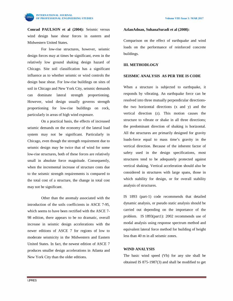
STOREY DRIFT FOR EARTH QUAKE LOAD:
Storey drift values for 1D.L+0.8(L.L+EQ.L)
Graph:
Storey drift values for load 1.2 (D.L+L.L+EQ)
Graph:
Storey drift for 1.2 (D.L+L.L+EQ)
INTERNATIONAL JOURNAL OF PROFESSIONAL ENGINEERING STUDIES Volume VIII /Issue 3 / MAR 2017
IJPRES
STOREY DRIFT FOR 1.5 (D.L+EQ)
Graph:
STOREY DRIFT FOR WIND LOAD (W.L):
Storey drift for 1D.L+0.8(L.L+W.L)
STOREY DRIFT FOR 1.2 (D.L+L.L+W.L)
STOREY DRIFT FOR 1.5 (D.L+W.L)

INTERNATIONAL JOURNAL OF PROFESSIONAL ENGINEERING STUDIES Volume VIII /Issue 3 / MAR 2017
IJPRES
STOREY SHEAR FOR EARTH QUAKE LOAD
STOREY SHEAR FOR 1D.L+0.8(L.L+EQ.L)
STOREY SHEAR FOR 1.2(D.L+L.L+EQ.L)
STOREY SHEAR FOR 1.5(D.L+EQ.L)
STOREY SHEAR FOR WIND LOAD (W.L)
STOREY SHEAR FOR 1D.L+0.8(L.L+W.L)
INTERNATIONAL JOURNAL OF PROFESSIONAL ENGINEERING STUDIES Volume VIII /Issue 3 / MAR 2017
IJPRES
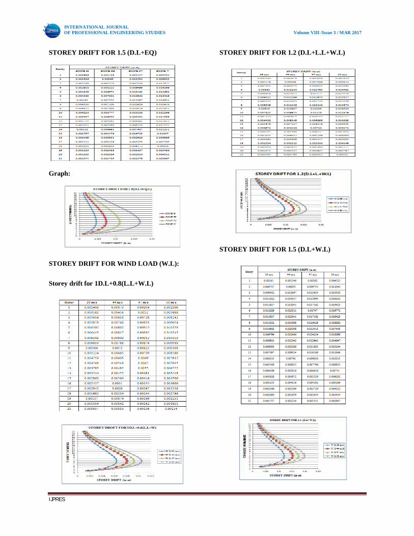
STOREY SHEAR FOR 1.2(D.L+L.L+W.L)
STOREY SHEAR FOR 1.5(D.L+W.L):
TORSIONAL FORCE FOR EARTH QUAKE
LOADS:
TORSION FOR 1D.L+0.8(L.L+EQ.L):
TORSION FOR 1.2(D.L+L.L+EQ.L):
INTERNATIONAL JOURNAL OF PROFESSIONAL ENGINEERING STUDIES Volume VIII /Issue 3 / MAR 2017
IJPRES
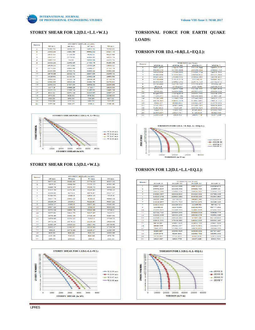
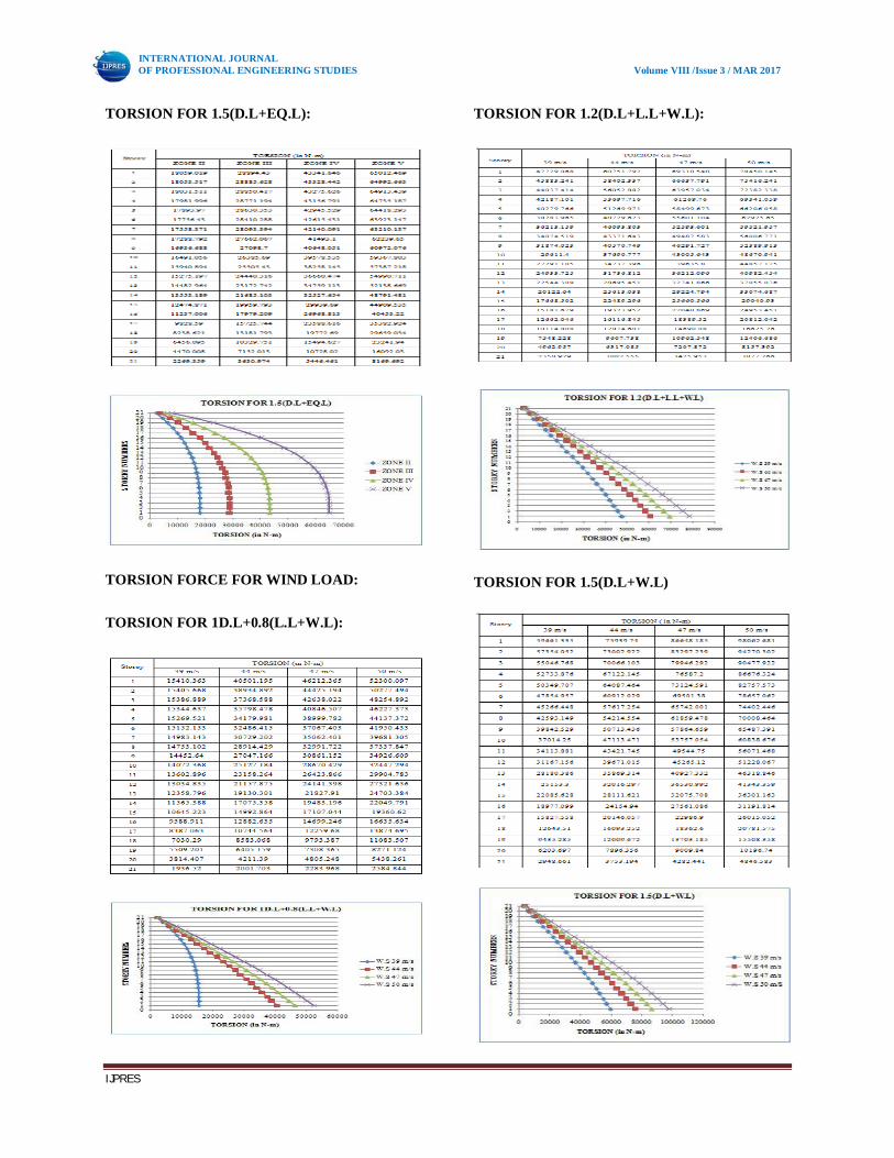
TORSION FOR 1.5(D.L+EQ.L):
TORSION FORCE FOR WIND LOAD:
TORSION FOR 1D.L+0.8(L.L+W.L):
TORSION FOR 1.2(D.L+L.L+W.L):
TORSION FOR 1.5(D.L+W.L)

INTERNATIONAL JOURNAL OF PROFESSIONAL ENGINEERING STUDIES Volume VIII /Issue 3 / MAR 2017
IJPRES
RESULTS OBTAINED BY RESPONSE
SPECTROM METHOD (RSM):
DISPLACEMENTS FOR SPEC X:
STOREY DRIFT FOR SPEC X:
STOREY SHEAR FOR SPEC X:
TORSION FOR SPEC X

INTERNATIONAL JOURNAL OF PROFESSIONAL ENGINEERING STUDIES Volume VIII /Issue 3 / MAR 2017
IJPRES
VI CONCLUSIONS
The Following conclusions are made from the present
study
1.The base shear of structure increases as we go to
higher seismic zones. For a similar building the base
shear value of ZONE II is 802.6 KN and ZONE V is
2889 KN. This means base shear increases by more
than 350% if seismic ZONE changes from II to V.
2.The displacement of building models increases with
the increasing of seismic Zones. The displacement is
very high at roof and very low at the base. The
displacement occur at the ZONE II is 0.1033 and
ZONE IV is 0.372. This means base shear increases
by more than 27% if seismic ZONE changes from II
to V.
3.The displacement of building models increases with
the increasing of wind pressure. The displacement is
very high at roof and very low at the base. The
displacement occurs at the wind space 39 m/s is
0.2411 and at the wind speed 50 m/s is 0.3963. This
means the displacement is increases by more than 50
% from wind speed 39 m/s to 50 m/s.
4.The storey drift is mainly occurred at the middle of
the building structure. From table 5.4 to 5.6 and fig
5.4 to 5.6, it is concluded that the storey drift
increases with the increasing of seismic zone factor.
And the maximum storey drift is available at ZONE
V for the max. Load combo at 7th floor. The storey
drift for ZONE II is 0.00887 and storey drift for
ZONE V is 0.016631m at 7 th floor. This means the
storey drift is increases by more than 50% when
compare to ZONE II to ZONE V.
5.The storey drift due to wind load is maximum at the
middle of the structure i.e., at 6th floor and it is
gradually increasing by increasing the wind pressure.
The value of storey drift at wind speed 39 m/s is
0.010545 and at high wind speed (50 m/s)
is0.019771. this means the storey drift is increases by
more than 150% if the wind speed changes low wind
speed (39 m/s) to high wind speed (50 m/s).
6. From results it is observed that the Storey Shear is
decreased as height of the building increased and
reduced at top floor in all the building models
subjected to seismic loads considered. The storey
shear is maximum at the base. And the storey shear
value for the model in ZONE II is151.29 and ZONE
V is 544.65.This means the storey shear is increases
by more than 27% when compare to ZONE II to
ZONE V.
7.From table 5.16-5.18 and fig 5.16-5.18 it is
concluded that as the seismic zone factor increases,
the torsion affect on the building is also increases.
And the torsion is mainly effect on base of the
building structure. The torsion at the base of the
model in ZONE II is 1815.487and ZONE V is
6535.754. This means the storey drift is increases by
more than 25% when compare to ZONE II to ZONE
V.
8.From table 5.19-5.21 and fig 5.19-5.21 it is
concluded that as the wind pressure increases, the
torsion affect on the building is also increases. And
the torsion is mainly effect on base of the building
structure. The torsion at the base of the model in 39
m/s is 59661.335 and 50m/s are 98062.681. This
means the torsion is increases by more than 50%
when compare to low wind pressure to high wind
pressure.

INTERNATIONAL JOURNAL OF PROFESSIONAL ENGINEERING STUDIES Volume VIII /Issue 3 / MAR 2017
IJPRES
9.By using shear walls, dampers, rubber pads, spring
we can reduce damage of seismic effect of an R C
building resting on high seismic zone.
REFERENCES
[1] IS: 1893 (Part 1), (2007), Indian Standard
Criteria for Earthquake Resistant Design of
Structures, Bureau of Indian Standards, New Delhi.
[2] IS: 456, (2000), Indian Standard Code of
Practice for Plain and Reinforced Concrete, Bureau
of Indian Standards, New Delhi.
[3] IITK-GDMA, (2005), IITK-GSDMA
Guidelines for Proposed Draft Code and
Commentary on Indian Seismic Code IS: 1893 (Part
1), IITK-GSDMA-EQ05-V4.0, August 2005, Indian
Institute of Technology Kanpur and Gujarat State
Disaster Mitigation Authority, Gandhi nagar, India.
[4] IS: 875 (Part 2): Code of Practice for Design
Loads (Other than Earthquake) For Buildings and
Structures. Part 2: Imposed Loads (Second Revision)
(1987).
[5] IS: 13920, (1993), Indian Standard Code of
Practice for Ductile Detailing of Reinforced Concrete
Structures Subjected to Seismic Forces, Bureau of
Indian Standards, New Delhi.
[6] Mariopaz-Structure Dynamics: Theory and
Computations, (Second Edition), CBS Publishers
&Distributors-New Delhi, 2004.
[7] Mahdihosseini , Ahmed najim Abdullah
alaskari,Prof.N.V.RamanaRao, International Journal
of Civil Engineering and Technology (IJCIET), ISSN
0976 –6316(Online), Volume 5, Issue 8, August
(2014).
[8] SunayanaVarma , B. Venugopal, K.
KarthikeyanInternational Journal of Civil
Engineering and Technology (IJCIET), ISSN 2321 –
919X(Online), Volume 2, Issue 8, August (2014).
[9] Chopra,A.K., (1982), Dynamics of
Structures A Primer, Earthquake Engineering
Research Institute, Oakland, California, USA.
[10] Chopra,A.K., (2012), Dynamics of Structures –
Theory and Application to Earthquake Engineering,
Fourth Edition, Prentice Hall Inc, USA.
[11]CSI, (2011), extended 3D analysis of building
structures (ETABS), Computers and Structures Inc.,
USA.
[12]Naeim,F. (Ed.), (2001), The Seismic Design
Handbook, Kluwer Academic Publishers, Boston,
USA.
[13]Itti,S.V.,Pathade.A.,andKaradi,R.B.(2011).‟A
Comparative Study on Seismic Provisions Made in
Indian and International Building Codes for RC
Buildings”