Embed Size (px)
Citation preview

HAL Id: hal-01946700https://hal.archives-ouvertes.fr/hal-01946700
Submitted on 6 Dec 2018
HAL is a multi-disciplinary open accessarchive for the deposit and dissemination of sci-entific research documents, whether they are pub-lished or not. The documents may come fromteaching and research institutions in France orabroad, or from public or private research centers.
L’archive ouverte pluridisciplinaire HAL, estdestinée au dépôt et à la diffusion de documentsscientifiques de niveau recherche, publiés ou non,émanant des établissements d’enseignement et derecherche français ou étrangers, des laboratoirespublics ou privés.
Analysis of flow and phase interaction characteristics ina gas-liquid two-phase pumpWenwu Zhang, Zhiyi Yu, Yongjiang Li
To cite this version:Wenwu Zhang, Zhiyi Yu, Yongjiang Li. Analysis of flow and phase interaction characteristics in agas-liquid two-phase pump. Oil & Gas Science and Technology - Revue d’IFP Energies nouvelles,Institut Français du Pétrole, 2018, 73, pp.69. �10.2516/ogst/2018072�. �hal-01946700�

Analysis of flow and phase interaction characteristics in a gas-liquidtwo-phase pumpWenwu Zhang, Zhiyi Yu*, and Yongjiang Li
School of Mechanical Engineering, Beijing Institute of Technology, Beijing 100081, PR China
Received: 16 May 2018 / Accepted: 24 September 2018
Abstract. To analyze the characteristics of internal flow and phase interaction in a gas-liquid two-phase pump,the influence of Inlet Gas Void Fraction (IGVF), discharge coefficient, and medium viscosity were investigatedusing medium combinations of air-water and air-crude. Simulations were performed using ANSYS_CFX at dif-ferent IGVFs and various values of discharge coefficient. Structured grid for the full flow passage was generatedusing ICEM_CFD and TurboGrid. Under conditions of IGVF = 0% (pure water) and IGVF = 15%, the reli-ability of numerical method was proved by means of the comparison with the experimental data of externalcharacteristic. The results for air-water combination showed a uniform gas distribution in the inlet pipe, andformation of a stratified structure in the outlet pipe. The gas in impeller gathered at the hub because of therotation of the impeller, also, the interphase forces increased with the increased IGVF. For the two mediumcombinations, the drag force was the largest interphase force, followed by added mass and lift forces, and thenthe turbulent dispersion force was the least, which can be neglected. Because of the larger viscosity of crudethan that of water, the variation trend of interphase forces in the impeller is relatively smooth along the flowdirection when the medium combination was air-crude.
1 Introduction
With the technological development and the demand forgas-liquid two-phase transport in industry, the gas-liquidmultiphase pump is widely used in petroleum, chemicalengineering, nuclear industries, etc. [1–4]. The gas-liquidmultiphase pump usually accompanied more complex inter-nal flow phenomena than the single-phase pump because ofits two-phase transport process including the polymeriza-tion and the division of bubbles, and the intermixing andthe separation among mediums.
Thus far, except for the optimization design, many stud-ies on multiphase pumps with the centrifugal or axial impel-ler were forced on the transport properties. For themultiphase pump with a centrifugal impeller, Minemuraand Murakami [5–7] investigated the motion of air bubblein a centrifugal pump, and obtained the controlling factorsfor the bubble motion including the pressure gradient, thedrag force, and the inertia force. Caridad et al. [8] simulateda centrifugal pump with two-phase flow conditions and con-cluded that the detriment in head increased with theincrease in bubble diameter. For the multiphase pump withan axial impeller, Zhang and Tan [9] analyzed the energyperformance and the pressure fluctuation in a multiphasepump. They found the gas distribution in the pump was
uneven because of the existence of density differencebetween the gas and liquid phases. Tremante et al. [10] car-ried out the simulation on a gas-liquid two-phase axial flowpump, and observed that the gas pockets appeared at theblade suction surface.
Interphase behavior is difficult to understand in two-phase flow field. Different studies on the gas-liquid phaseinteraction have been conducted for same and different flowpatterns at different IGVFs [11–13]. These studies wereconducted using the horizontal or inclined pipes only inthe non-rotating machinery. Whereas the flow is more dis-ordered in multiphase pumps than that in static pipesbecause of the rotor-stator interaction. Although Yu et al.[14] analyzed the variation trend of the interphase forcesin a single impeller passage, the understanding of the gas-liquid interphase behavior in multiphase rotodynamicpumps is still insufficient. Meanwhile, considering the com-plexity, safety and reusability of the testing system of mul-tiphase pumps, the air-water combination has been usuallyused as the working medium [15]. Thus, few studies havebeen performed on the characteristics of phase interactionas well as the difference of transport properties caused bythe change of medium viscosity in multiphase pumps.
On the basis of the above introduction, the three-dimen-sional (3D) simulation of the gas-liquid flow in a multiphasepump for a full passage was carried out in this study. Fur-thermore, the medium combinations of air-water, and* Corresponding author: [email protected]
This is an Open Access article distributed under the terms of the Creative Commons Attribution License (http://creativecommons.org/licenses/by/4.0),which permits unrestricted use, distribution, and reproduction in any medium, provided the original work is properly cited.
Oil & Gas Science and Technology - Rev. IFP Energies nouvelles 73, 69 (2018) Available online at:� W. Zhang et al., published by IFP Energies nouvelles, 2018 www.ogst.ifpenergiesnouvelles.fr
https://doi.org/10.2516/ogst/2018072
REGULAR ARTICLEREGULAR ARTICLE

air-crude were used to explore the distribution of Gas VoidFraction (GVF) as well as the interphase behavior of thegas-liquid two-phase flow in the impeller, and the inletand outlet pipes. The purpose of this study is to havefurther understanding of the effects of different inlet param-eters (inlet gas void fraction, discharge, medium viscosity)on the characteristics of flow and phase interaction in suchpumps.
2 Computational model and structured grid
The study was conducted on a helico-axial flow pump deal-ing with a gas-liquid two-phase flow. Its main design spec-ifications are described below: the diameter of impeller (D)was 210 mm, the numbers of impeller blades (Z) were 4, thedischarge (Qd) was 35.45 m3/h, the rotating speed (n) was1500 r/min, and the head (H) was 15 m. Figure 1 shows thecalculation model of the multiphase pump with its inlet andoutlet pipes, and impeller.
The grids of the inlet and outlet pipes and the impellerwere generated with ICEM_CFD and TurboGrid, respec-tively, as shown in Figure 2. Furthermore, H/J/C/Otopologies were adopted for the impeller to ensure its gridquality. In addition, the analysis for grid independencewas conducted at three discharge conditions (u = 0.034,0.043, 0.051) to reduce the computational memory andtime, as listed in Table 1. Here, by adjusting the size of ele-ments next to the wall, the y+ values of the impellerextracted through CFD_Post for these four grid densitieswere kept around 20. It shows that these four grid densitieshave no great effect on the pump head. Therefore, Grid _Iwas finally adopted in the present study.
3 Numerical methodology
3.1 Governing equations
Two-fluid model was adopted in this study to predict theinternal flow of the multiphase pump. In this model, eachfluid has its own conservation equations and various inter-actions between the two fluids are considered. Therefore,two-fluid model has been widely used in recent yearsbecause of its high computational accuracy [16–18]. Mean-while, in this study, ANSYS_CFX 15.0 was implementedto solve the steady Reynolds-Averaged Navier-Stokes(RANS) equations. The governing equations for incom-pressible fluid are written below [19–22].
Continuity equation:
r � akqkwkð Þ ¼ 0: ð1Þ
Momentum equation:
r � akqkwkwk � aksð Þ ¼ �akrp þMk þ akqkf k; ð2Þ
where s denotes the viscous stress tensor; ak, Mk, fk, andwk stand for the void fraction, the interphase force, themass force, and the velocity of k phase, respectively.
Meanwhile, SST k-x turbulence model was applied forsolving the turbulent viscosity. In this model, the k-e and
k-x models are implemented for the boundary layer andthe main flow regions, respectively, thus it can predict accu-rately for the flow separation in the pump [23]:
lt ¼qmixa1k
max a1x; SF 2ð Þ ; ð3Þ
here, a1 is the model constant (a1 = 5/9); S, qmix, F2 rep-resent the invariant measure of strain rate, the mixturedensity, and the blending function, respectively.
3.2 Interphase force
In addition to the centrifugal force, inertia force, gravityand the pressure difference, the two phases in the multi-phase pump are also experienced the interphase forces.The interphase forces were extracted using the CFXExpression Language (CEL) and analyzed in this study.Furthermore, the interphase forces in the gas-liquid two-phase flow mainly include the drag, added mass force, lift,turbulent dispersion force as well as Basset effect andMagnus effect [24], while the latter two can be neglectedfor the internal flow in multiphase pumps [25, 26]. Thus,the total gas-liquid interphase force in this study wasexpressed as follows:
Mk ¼ Dk þ Lk þTk þAk; ð4Þ
Fig. 1. 3D calculation model of the multiphase pump.
Fig. 2. Structured grid for impeller passage.
W. Zhang et al.: Oil & Gas Science and Technology - Rev. IFP Energies nouvelles 73, 69 (2018)2

where Dk, Lk, Tk and Ak denote the interphase forces ofdrag, lift, turbulent dispersion and added mass,respectively.
The drag models involved in the gas-liquid two-phaseflow mainly include Ishii Zuber, Grace, and SchillerNaumann models. The former two are closely related tothe particle shapes, and they are rarely used in the simula-tion of the multiphase pump. Therefore, the widely appliedSchiller Naumann model was considered in this study[27, 28]. The drag force per unit volume can be describedas follows:
Dl ¼ �Dg ¼34CD
ql
Dbag wg �w1
��
�� wg �wl� �
ð5Þ
here, wg and w1 represent the velocity of gas and liquid,respectively; Db is the diameter of gas bubble and is given0.4 mm according to the experimental value; and CD isthe drag coefficient. According to the references [14, 29],the drag coefficient was modified through the CFXexpression language (CEL) and expressed as:
CD ¼ max24Reb
1þ 0:1Re0:75b
� �
;23
Db
ffiffiffiffiffiffiffiffiffiffiffiffiffiffiffiffiffiffiffi
ql � qg
� �
r
s
1� ag
� ��0:5
0
@
1
A
ð6Þ
where r is the surface tension coefficient; ql and qg are thedensity of liquid and gas; ag is the gas void fraction; Reb isthe bubble Reynolds number and given as follows:
Reb ¼qlDb wl �wg
��
��
ll1� ag
� �
ð7Þ
where ll is the liquid molecular viscosity. The lift, turbu-lent dispersion and added mass forces can be described bythe following expressions (8)–(10), respectively:
Ll ¼ �Lg ¼ CLagql wg �wl
� �
� r�wlð Þ ð8Þ
T l ¼ �Tg ¼ �CT qlkral ð9Þ
Al ¼ �Ag ¼ �qlCAagDwg
Dt�Dwl
Dt
� �
ð10Þ
where k is the turbulence kinetic energy of liquid. Accord-ing to the relevant research by far, the coefficients of lift,
turbulent dispersion and added mass forces were usuallykept constant, i.e., CL = 0.5 [30], CT = 0.1 [14], andCA = 0.5 [31].
3.3 Settings of simulation and medium properties
The settings of simulation and the properties of air-waterand air-crude medium combinations are presented inTables 2 and 3, respectively. Especially, it can be obtainedfrom Table 3 that the smaller density difference existsbetween water and crude, while the viscosity of crude isabout thirty-one times as large as that of water.
4 Results and discussions
4.1 Test system and validation of simulation results
A schematic diagram of the testing system is presented inFigure 3. Here, considering the complexity, safety andreusability of the testing system, a combination of air-waterwas chosen as the transporting medium. In this testing sys-tem, the air was provided by a compressor and evenlymixed with the water in a mixer before entry into the mul-tiphase pump, that is, the flow pattern is bubbly flow in theinlet pipe. The water pipeline was the closed cycle, while theair pipeline was open system, and after one cycle, the gaswill spill out from the water tank. Experimental measure-ments at different discharges and IGVFs were made intwo steps, the first was to fix the liquid discharge, andthe second was the control of total mass discharge byadjusting the gas valve. Meanwhile, the float and turbineflowmeters, with an accuracy of ±0.5%, were installed toobtain the air and water discharges, respectively. A torquesensor with an accuracy of ±0.1% was used to monitor therotating speed and torque of the pump, and the pres-sure gauges with an accuracy of ±0.25% were installed atthe inlet and outlet of the pump so as to obtain the testedhead.
Figure 4 presents the numerical and experimentalresults under conditions of IGVF = 0% (pure water) andIGVF = 15% when the rotating speed of the pump is1500 r/min. Here, the calculations of IGVF, discharge coef-ficient u (horizontal axial), and head coefficient w (verticalaxial) are described by the following expressions,respectively:
IGVF ¼ Qg= Qg þ Ql
� �
ð11Þ
Table 1. Analysis for grid independence.
H/HI
Items Inlet pipe Outlet pipe Impeller Whole passage u = 0.034 u = 0.043 u = 0.051
Grid_I 518 364 373 932 1 925 608 2 817 904 1 1 1Grid_II 518 364 373 932 2 332 168 3 224 464 0.9980 0.9994 0.9962Grid_III 602 482 463 932 2 903 646 3 970 060 0.9980 0.9988 0.9949Grid_IV 698 362 524 812 3 241 862 4 465 036 0.9975 0.9971 0.9947
Note. HI is the head at Grid_I condition.
W. Zhang et al.: Oil & Gas Science and Technology - Rev. IFP Energies nouvelles 73, 69 (2018) 3

/ ¼ cm2=u2 ð12Þ
w ¼ gH=u22 ð13Þ
where Qg and Ql represent the volume discharge of gasand liquid, respectively, at the inlet, and cm2 and u2 rep-resent the meridional velocity and the circumferentialvelocity at impeller outlet, respectively. The discharge-head performance curves from the simulation showedclose agreement with the experiment. The errors of headat design conditions of IGVF = 0 and IGVF = 15% are1.39% and 4.9%, respectively. Therefore, the simulationmodel used in the present study is reliable.
4.2 Influence of IGVF on gas-liquid flow characteristics
Through the CFD_Post, the area average of GVF alongthe flow direction was obtained at different IGVFs(5%, 15%, and 25%) and a total discharge coefficient u of0.043 for the air-water medium, as shown in Figure 5.At these three IGVF conditions, a uniform gas distributionappeared at the inlet pipe, while the gas in the impellermainly gathered at the hub. This accumulation was attrib-uted to the rotating effect of the impeller. The liquid phase,with a greater density, experienced larger centrifugal force,and as a result, moved towards the impeller shroud,whereas the gas gathered near the impeller hub.
Table 2. Settings of boundaries and solutions.
Types Items Settings
Boundaries Inlet Total mass discharge and corresponding IGVFOutlet Average static pressureWall No-slipRotor-stator interfaces Frozen-stator
Solutions Advection term Second order upwind schemeTurbulence term Second order upwind schemeRMS residual 1 · 10�4
Table 3. Medium properties in the simulation.
Items Air Water Crude
Molar mass (kg kmol�1) 29.0 18.0 300Density (kg m�3) 1.2 997 863Dynamic viscosity (kg m�1 s�1) 1.8 · 10�5 8.9 · 10�4 273.6 · 10�4
Fig. 3. Schematic diagram of the testing system.
W. Zhang et al.: Oil & Gas Science and Technology - Rev. IFP Energies nouvelles 73, 69 (2018)4

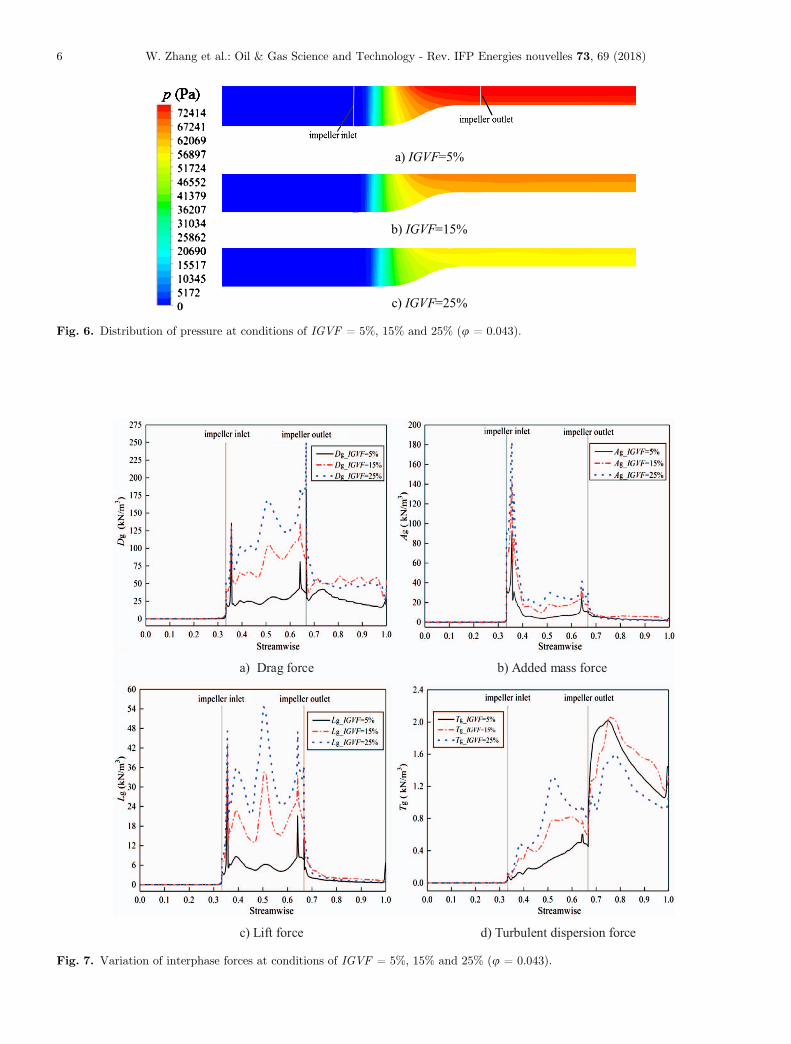
When the IGVF value was raised, the degree of gasaggregation in the impeller hub and the gas inhomogeneityin the entire impeller increased, resulting in the reduction ofpressure boosting of the pump, as shown in Figure 6. Fur-thermore, it can be seen from Figure 5 that a stratifiedstructure appeared in the outlet pipe, that is, the gas andthe liquid accumulated at the hub and the shroud, respec-tively. This is caused by the movement of gas. Because ofthe inertia, the gas accumulating near the impeller hub willmove along the streamwise direction, thus the gas-liquidstratified structure came into being. Moreover, the stratifiedstructure became more obvious with the increase in IGVF.
The area average of interphase forces, extracted from theinlet to the outlet of computational domain, are shown inFigure 7. Overall, the drag force, as well as the added massand lift forces, firstly increased and then decreased along the
flow direction, while the turbulent dispersion force increasedgradually. The comparing of the magnitude of these fourinterphase forces showed that the drag force was the largest,followed by the added mass and lift forces, and then the tur-bulent dispersion force, where the value of the turbulent dis-persion force was negligible relative to the other forces.
From Figure 7, it can be also observed that the inter-phase forces in the impeller passage became large with theincreased IGVF. This is because the GVF is one of the fac-tors that affect the interphase forces of drag, lift, and addedmass according to Equations (5), (8) and (10), and has apositive correlation with them. While Equation (9) showsthat the turbulent dispersion force has a positive correlationwith the varying gradient of phase void fraction, and com-bined with Figure 5, the varying gradient of phase void frac-tion increased with the increased IGVF.
a) IGVF=0% b) IGVF=15%
Fig. 4. Discharge-head curves for simulation and experiment.
a) IGVF=5%
b) IGVF=15%
c) IGVF=25%
Fig. 5. Distribution of GVF at conditions of IGVF = 5%, 15% and 25% (u = 0.043).
W. Zhang et al.: Oil & Gas Science and Technology - Rev. IFP Energies nouvelles 73, 69 (2018) 5
a) Drag force b) Added mass force
c) Lift force d) Turbulent dispersion force
Fig. 7. Variation of interphase forces at conditions of IGVF = 5%, 15% and 25% (u = 0.043).
a) IGVF=5%
b) IGVF=15%
c) IGVF=25%
Fig. 6. Distribution of pressure at conditions of IGVF = 5%, 15% and 25% (u = 0.043).
W. Zhang et al.: Oil & Gas Science and Technology - Rev. IFP Energies nouvelles 73, 69 (2018)6

4.3 Influence of discharge coefficient on gas-liquidflow characteristics
For the air-water medium at IGVF of 25%, the variationtrend of the interphase forces along the flow direction inimpeller at different total discharge coefficients(u = 0.034, 0.043, 0.051) are displayed in Figure 8. Thedrag force, as well as the added mass and lift forces, nearthe impeller inlet increased significantly, which wasclosely related to the incidence angle that depends on thedischarge coefficient. Because of the inconsistency betweenthe incidence angle and the blade angle, the flow nearthe impeller inlet was more disordered, resulting in theenlarged local velocity difference between the two phases(Fig. 10).
Figure 8 also shows that the drag and lift forces gener-ally increased with the decrease in discharge coefficient.This is because, when the discharge coefficient decreased,the GVF near the impeller hub, and the velocity differencebetween gas and liquid near the impeller inlet, increased
obviously (Figs. 9 and 10), then combined with the corre-sponding equations, it can be concluded that these twointerphase forces would increase. The interphase forces
a) Drag force b) Added mass force
c) Lift force
Fig. 8. Variation of interphase forces in the impeller at different discharge coefficients (IGVF = 25%).
a) φ1 = 0.034
b) φ2 = 0.043
c) φ3 = 0.051
Fig. 9. Variation of GVF near the impeller hub at differentdischarge coefficients (span = 0.1, IGVF = 25%).
W. Zhang et al.: Oil & Gas Science and Technology - Rev. IFP Energies nouvelles 73, 69 (2018) 7

increased dramatically when the discharge coefficientdecreased to 0.034. This was due to the large deviationbetween the incidence angle and the blade angle at
u = 0.034. The flow separation occurred near the SuctionSurface (SS), and the gas-liquid velocity differenceincreased. This caused the water motion from the Pressure
a) φ1 = 0.034b) φ2 = 0.043c) φ3 = 0.051
Fig. 10. Variation of velocity difference between gas and liquidnear the impeller hub at different discharge coefficients(span = 0.1, IGVF = 25%).
a) Air-water
b) Air-Crude
Fig. 11. Variation of GVF at impeller meridional surface(u = 0.043, IGVF = 25%).
a) Drag force b) Added mass force
c) Lift force d) Turbulent dispersion force
Fig. 12. Variation of interphase forces in the impeller for different medium combinations (u = 0.043, IGVF = 25%).
W. Zhang et al.: Oil & Gas Science and Technology - Rev. IFP Energies nouvelles 73, 69 (2018)8

Surface (PS) to the suction surface resulting in high accu-mulation of gas near the suction surface (Fig. 9).
4.4 Influence of viscosity on gas-liquid flowcharacteristics
To explore the influence of transport medium viscosity onthe two-phase flow characteristics in multiphase pumps,the area average of GVF at impeller meridional surface atu = 0.043, and IGVF = 25%, for air-water and air-crudemediums are shown in Figure 11.
For these two medium combinations, the regularities ofgas distribution were similar, namely it gathered at theimpeller hub and the closer to the impeller outlet, the higherdegree of gas aggregation. Meanwhile, the gas void fractionnear the impeller hub was lower for the air-crude in compar-ison with the air-water medium. This is because the viscos-ity of crude is much greater than that of water, while smalldensity difference exists between these two mediums, thusresulting in the smaller Reynolds number for crude at thesame value of discharge coefficient. The viscosity force ofthe crude had a greater effect on the field, and the flowvelocity disturbed by the impeller was attenuated becauseof the greater viscosity, resulting in the lower gas void frac-tion near the impeller hub for the air-crude medium.
Figure 12 shows the variation trend of interphase forcesin the impeller at conditions of u = 0.043, IGVF = 25%.For the air-crude medium, the drag force was the largestinterphase force, followed by the added mass and lift forces,and then the turbulent dispersion force was the least, whichcan be neglected because of the smaller magnitude relativeto the other forces.
The comparison of the interphase forces at these twomedium combinations showed that for the air-crude combi-nation, the variation trend of the interphase forces was rel-atively smooth along the flow direction. This is due to thelarger viscosity of crude than that of water for the air-crudemedium. The flow velocity disturbed by the impeller wasattenuated because of the greater viscosity, thus, reducingthe disorder of flow.
5 Conclusion
The purpose of this study is to explore the effects of differ-ent inlet parameters (inlet gas void fraction, discharge,medium viscosity) on the characteristics of flow and phaseinteraction in a gas-liquid multiphase pump, which is con-tribute to the optimization design for such pumps. Throughthe numerical calculation, several conclusions can beobtained below:
When the medium is the combination of air-water, auniform gas distribution appeared at the inlet pipe, and astratified structure was formed in the outlet pipe, whilethe gas in the impeller gathered at the hub because of therotation effect of impeller. The interphase forces along theflow direction firstly increased and then decreased exceptthe turbulent dispersion force, which increased gradually.Meanwhile, all the four interphase forces in impeller wereincreased with the increased IGVF.
When the medium is the combination of air-water,because of the inconsistency between the incidence angleand the blade angle, the drag force, as well as the addedmass and lift forces, near the impeller inlet increased signif-icantly. As the discharge coefficient decreased, the gas voidfraction near the impeller hub, and the gas-liquid velocitydifference near the impeller inlet increased obviously, result-ing in the increased drag and lift forces.
For the two medium combinations, the regularities ofgas distribution were similar, namely it gathered at theimpeller hub and the closer to the impeller outlet, the higherdegree for gas aggregation. Due to the larger viscosity ofcrude, the flow velocity disturbed by the impeller was atten-uated, which resulted in the lower gas void fraction near theimpeller hub for air-crude medium.
For the two medium combinations, the drag force wasthe largest interphase force, followed by the added massand lift forces, and then the turbulent dispersion forcewas the least and thereby can be neglected. Due to the lar-ger viscosity of crude than that of water, the variation trendof the interphase forces in impeller was relatively smooth forthe air-crude medium.
Acknowledgments. This study was supported by the NationalNatural Science Foundation of China (grant no. 51579006),and Basic Research Foundation of Beijing Institute of Technol-ogy (grant No. 20150342012).
References
1 Liu X., Liu C., Yang Y. (2017) Dynamic behavior ofthe polished rod for the coalbed methane pumping installa-tions, Oil Gas Sci. Technol. - Rev. IFP Energies nouvelles72, 16.
2 Falcimaigne J., Brac J., Charron Y., Pagnier P., Vilagines R.(2002) Multiphase pumping: achievements and perspectives,Oil Gas Sci. Technol. - Rev. IFP Energies nouvelles 57, 1,99–107.
3 Omrani A., Franchek M., Ebrahimi B., Mutlu M.,Grigoriadis K. (2017) Low-dimensional modeling of a pump-ing unit to cope with multiphase, J. Dyn. Syst. Mea. Control.139, 4, 1–4.
4 Pirouzpanah S., Gudigopuram S., Morrison G. (2016) Two-phase flow characterization in a split vane impeller ElectricalSubmersible Pump, J. Petrol. Sci. Eng. 148, 82–93.
5 Minemura K., Murakami M. (1980) A theoretical study onair bubble motion in a centrifugal pump impeller, J. Fluid.Eng. - ASME 102, 446–453.
6 Minemura K., Murakami M. (1993) Three-dimensionalcalculation of air-water twophase flow in centrifugal pumpimpeller based on a bubbly flow model, J. Fluid. Eng. - ASME115, 766–771.
7 Minemura K., Murakami M. (1974) Effects of entrained airon the performance of a centrifugal pump, Bull. Japan Soc.Mech. Eng. 112, 1286–1295.
8 Caridad J., Asuaje M., Kenyery F., Tremante A., Aguillon O.(2008) Characterization of a centrifugal pump impeller undertwo-phase flow conditions, J. Petrol. Sci. Eng. 63, 18–22.
9 Zhang J.S., Tan L. (2018) Energy performance and pressurefluctuation of a multiphase pump with different gas volumefractions, Energies 11, 1–14.
W. Zhang et al.: Oil & Gas Science and Technology - Rev. IFP Energies nouvelles 73, 69 (2018) 9

10 Tremante A., Moreno N., Rey R. (2002) Numerical turbulentsimulation of the two-phase flow (liquid/gas) through a cas-cade of an axial pump, J. Fluid. Eng. - ASME 124, 371–376.
11 Ishii M., Zuber N. (1979) Drag coefficient and relativevelocity in bubbly, droplet or particulate flows, AIChE J. 25,843–855.
12 Ion I., Mostafa F., Faı̈cal L. (2003) Hydrodynamic model forhorizontal two-phase flow through porous media, Can. J.Chem. Eng. 81, 957–962.
13 Laurien E., Niemann J. (2004) Determination of the virtualmass coefficient for dense bubbly flows by direct numericalsimulation, 5th International Conference on Multiphase Flow,Yokohama, Japan, June.
14 Yu Z.Y., Zhu B.S., Cao S.L. (2015) Interphase force analysisfor air-water bubbly flow in a multiphase rotodynamic pump,Eng. Comput. 32, 2166–2180.
15 Zhang W.W., Yu Z.Y., Zahid M.N., Li Y.J. (2018) Study ofthe gas distribution in a multiphase rotodynamic pump basedon interphase force analysis, Energies 11, 1–16.
16 Lee D., Best F.R., McGraw N. (1987) Microgravity two-phase flow regime modeling, Proceedings of the NuclearSociety Winter Meeting, Los Angeles, CA, USA, November.
17 Benhmidene A., Chaouachi B., Bourouis M., Gabsi S. (2011)Numerical prediction of flow patterns in bubble pumps,J. Fluid. Eng. - ASME 133, 1–8.
18 Situ R., Hibiki T., Brown R.J. (2011) Flow regime transitioncriteria for two-phase flow at reduced gravity conditions, Int.J. Multiph. Flow. 37, 1165–1177.
19 Zhang W.W., Yu Z.Y., Zhu B.S. (2017) Numerical study ofpressure fluctuation in a gas-liquid two-phase mixed-flowpump, Energies 10, 1–14.
20 Tan L., Zhu B.S., Cao S.L., Wang Y.C., Wang B.B. (2013)Numerical simulation of unsteady cavitation flow in acentrifugal pump at off-design conditions, Proc. Inst. Mech.Eng. C: J. Mech. Eng. Sci. 228, 1994–2006.
21 Tan L., Zhu B.S., Cao S.L., Wang Y.M. (2013) Cavitationflow simulation for a centrifugal pump at a low flow rate,Chin. Sci. Bull. 58, 949–952.
22 Such J.W., Kim J.W., Choi Y.S., Kim J.H., Joo W.G., LeeK.Y. (2017) Multi-objective optimization of the hydrody-namic performance of the second stage of a multi-phasepump, Energies 10, 1–21.
23 Zhang W.W., Yu Z.Y., Zahid M.N., Li Y.J. (2018)Study of the gas distribution in a multiphase rotodynamicpump based on interphase force analysis, Energies 11, 5,1–16.
24 Liu D.Y. (1993) Fluid Dynamics of two-phase systems, HigherEducation Press, Beijing, China, pp. 26–31.
25 Yu Z.Y., Zhu B.S., Cao S.L., Liu Y. (2015) Effect of virtualmass force on the mixed transport process in a multiphaserotodynamic pump, Adv. Mech. Eng. 6, 1–7.
26 Johnson R.W. (1998) The handbook of fluid dynamics, BocaRaton, FL, USA, pp. 21–22.
27 Schiller L., Naumann A. (1993) Fundamental calculations ingravitational processing, Z. Ver. Dtsch. Ing. 77, 318–320.
28 Zhang J.Y., Li Y.J., Cai S.J., Zhu H.W., Zhang Y.X. (2016)Investigation of gas-liquid two-phase flow in a three-stagerotodynamic multiphase pump via numerical simulation andvisualization experiment, Adv. Mech. Eng. 8, 1–13.
29 Tabib M.V., Schwarz P. (2011) Quantifying sub-grid scale(SGS) turbulent dispersion force and its effect using one-equation SGS large eddy simulation (LES) model in a gas-liquidand a liquid-liquid system, Chem. Eng. Sci. 66, 3071–3086.
30 Mohajerani M., Mehrvar M., Eincmozaffari F. (2012) CFDanalysis of two-phase turbulent flow in internal airliftreactors, Can. J. Chem. Eng. 60, 1611–1630.
31 Pourtousi M., Sahu J.N., Ganesan P. (2014) Effect ofinterfacial forces and turbulence models on predicting flowpattern inside the bubble column, Chem. Eng. Process:Process Intensification 75, 38–47.
W. Zhang et al.: Oil & Gas Science and Technology - Rev. IFP Energies nouvelles 73, 69 (2018)10