Embed Size (px)
DESCRIPTION
Research Article
Citation preview
Wear 296 (2012) 607–618
Contents lists available at SciVerse ScienceDirect
Wear
0043-16
http://d
n Corr
E-m
journal homepage: www.elsevier.com/locate/wear
Analysis of experimentally generated friction related acousticemission signals
Kassahun Asamene, Mannur Sundaresan n
Department of Mechanical Engineering, North Carolina A&T State University, Greensboro, NC 27411, USA
a r t i c l e i n f o
Article history:
Received 14 October 2011
Received in revised form
18 July 2012
Accepted 18 July 2012Available online 7 August 2012
Keywords:
Friction
Acoustic emissions
Stick-slip
Machinery condition monitoring
Structural health monitoring
48/$ - see front matter & 2012 Elsevier B.V. A
x.doi.org/10.1016/j.wear.2012.07.019
esponding author. Tel.: þ1 336 334 7620 x31
ail address: [email protected] (M. Sundaresa
a b s t r a c t
Acoustic emission signals generated by sliding friction between two flat steel surfaces are character-
ized. A test fixture to simulate the reciprocating motion between the two surfaces under controlled
conditions is developed. Sliding friction under several combinations of surface roughness, relative
velocity, and normal pressure was examined. Wideband AE sensors and instrumentation were used for
acquiring and analyzing the acoustic emission signals. Acoustic emission events occurred primarily
during the slip portion of the stick-slip cycles. AE waveform features obtained during these experi-
ments were indicative of the tribological conditions. Frequency components in excess of 700 kHz were
seen during these experiments. The characteristics of the experimentally observed acoustic emission
signals were in general agreement with earlier numerical predictions. Friction related acoustic emission
signals were distinguishable from those from other sources such as fatigue crack growth. The
characterization of friction related acoustic emission signals is likely to be of value in many tribological
and structural health monitoring applications.
& 2012 Elsevier B.V. All rights reserved.
1. Introduction
Acoustic emissions (AE) are stress waves generated in solidsdue to the release of strain energy by a variety of mechanisms.A number of mechanical processes, including incremental crackgrowth, slip between surfaces that are in contact, and phasetransformations in crystalline materials, can generate acousticemission signals. AE signals carry information about the details ofthe physical processes that are responsible for such signals.Analysis of acoustic emission signals have been traditionally usedfor nondestructive testing and monitoring structures duringqualification tests. A number of studies in the past have analyzedAE signals to understand the individual processes involved indamage growth in materials such as crack growth. Machinerycondition monitoring using AE technique has received significantattention in the recent past. In such studies, AE signals have beenused to recognize the extent of degradation of the contactsurfaces, such as those in bearings and gears.
AE signals are generated during sliding motion in bearings,gears, and turbine blade root joints as well as in bolted andriveted joints. Changes in the pattern of AE signals have been usedin the past to indicate surface damage. These surfaces, whilesmooth on a macroscopic scale, have roughness or asperitieswhose dimensions may be of the order of microns. During the
ll rights reserved.
3; fax: þ1 336 334 7417.
n).
relative motion between two surfaces in contact, the asperities onone surface attempt to slide past the asperities on the oppositesurface, which results in the collision between these asperitiesand sudden loading and unloading of regions in their immediatevicinity. The interactions between pairs of asperities may last avery short duration, of the order of few microseconds. Thetransient forces accompanying such interactions between aspe-rities are a prolific source of elastic waves that are sensed asacoustic emission signals. Furthermore, such relative displace-ment between surfaces can also lead to plastic deformation andfracture of asperities and accumulation of wear particles betweensurfaces, each of which can also generate acoustic emissionsignals. Baranov [1] summarizes the sources of AE during frictionconventionally into three groups: impact of friction surface atmicroscopic level (asperity collision), surface damage, formationand rupture of adhesion junctions.
Repetitive relative motion of the surfaces over longer periods leadsto change in the roughness and texture of the surface, and it can beexpected that acoustic emission signals may be indicative of thesechanges. The first group of papers reviewed here examines therelationship between the acoustic emission signal characteristicsand the conditions prevailing at the contacting surfaces. Dornfeld[2] performed early studies to understand the relationship betweenthe AE signals and sliding friction. Jibiki et al. [3] studied AE signalsgenerated by friction over a small contact area between two cylindersarranged such that their axes were 901 apart. The friction noise forrepetitive cycles of sliding at ‘‘point’’ contact of the cylinders wasrecorded using a microphone. The main frequency component of the
K. Asamene, M. Sundaresan / Wear 296 (2012) 607–618608
detected acoustical signal was a little more than 1 kHz. The amplitudeof the AE signal was found to increase as the fretting stroke or thefrequency was increased. Furthermore, the amplitude of the AE signalwas also found to increase with the level of the surface wear. Ferreret al. [4] studied the acoustic emission waves generated duringtransition from static to dynamic friction. Resonant frequency AEsensors were used in these experiments to record the signals. Theyexperimentally simulated stick-slip conditions between a pair of padsand a flat plate during a single stroke and recorded the resultingacoustic emission signals. The different segments of the recordedwaveforms were related to different segments of the slip processincluding micro-slip, partial slip and gross slip. Abdelounis et al. [5]examined noise generated by friction between two flat surfaces usingthe microphones. As the surface roughness was increased, theamplitude of the acoustical signal was found to increase as alogarithmic function of the surface roughness. The relationshipbetween AE signal characteristics and friction and wear was alsostudied by Hase [6] and Hisakado [7]. Parameters of the signals suchas count, count rate, and amplitude were considered in the analyses.
Theoretical models of acoustic emission signal generation dueto friction are also available. Fan et al. [8] analyzed the relation-ship between AE energy and the surface characteristics, contactload, and sliding velocity. Baranov et al. [9] determined the AEactivity levels in terms of acoustic emission counts, count rate,and energy corresponding to different conditions that exist at thecontact surfaces. Alam et al. [10] numerically simulated the AEsignal generation and propagation in a flat plate. Detailed char-acteristics of AE signals corresponding to different conditionsprevailing at the contact surface were determined.
The second group of papers is on the use of acoustic emission fordiagnosis of the condition of machinery, specifically surface degra-dation in bearings and gear trains. Li [11] used pattern classificationto monitor defects in bearings using AE signals. Al-Dossary [12]investigated the variation in RMS voltage of AE bursts to quantifyimplanted defects in the roller bearings. Measurement and analysisof AE signals were used in condition monitoring of gears [13–14].Experiments based on back-to-back gearbox setup were used tomonitor changes in AE RMS voltage and energy.
Jayakumar [15] provided a review of application of AE techni-que for online monitoring of a variety of manufacturing processes.It was found that acoustic emissions generated during differentforming processes provide useful information for detecting diewear and cracking, friction properties, state of lubrication, and
Fig. 1. Friction t
others. Meriaux [16] studied crack propagation mechanisms infretting fatigue using acoustic emissions. In addition, AE signalsresulting from sliding motion, friction and wear in differentmechanical elements were studied. [17–21]
The above studies specifically considered acoustic emissionsignals due to relative motion between surfaces in contact. Inaddition, some findings from other studies, which directly look atthe relationship between the surface features and coefficient offriction, are also relevant for interpreting acoustic emission signals.Menezes [22] examined the effect of surface texture and wear onthe coefficient of friction. The coefficient of friction was found to beindependent of the value of roughness but showed significantdependence on texture. Philipon [23] studied the coefficient offriction at high sliding velocities, typical of a projectile slidingagainst a surface. Other studies dealt with the friction–velocityrelationship [24], modeling of multi-asperity contacts [25,26], andfretting fatigue analysis [27,28]. The analysis of the frictionalprocesses operating at various length scales, ranging from nan-ometers to macro scale, has been studied using a variety of tools[29–31]. Preliminary results from the current study [32] provided anunderstanding of friction related AE signals.
In the present paper, sliding motion between two dry flat steelsurfaces in contact is examined. AE signals generated by thefriction between the two surfaces are measured and analyzed. Theobjective of this work is to examine if AE signals carry recogniz-able features that can reveal the conditions prevailing at theinterface where frictional sliding is taking place. The conditionsinclude surface roughness, normal pressure as well as the dura-tion and velocity of sliding. AE signals were acquired for eightdifferent combinations of these parameters. Features of acousticemission waveforms due to sliding motion such as amplitude,frequency, and duration for different combinations of test condi-tions are examined. These results are likely to be of relevance forAE based machinery diagnostics and structural health monitoring.Details of the work are presented in the following sections.
2. Experimental test setup
2.1. Test fixture
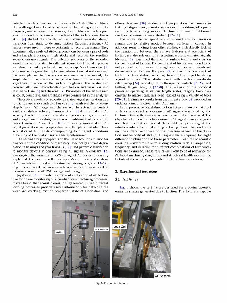
Fig. 1 shows the test fixture designed for studying acousticemission signals generated due to friction. This fixture is capable
est fixture.
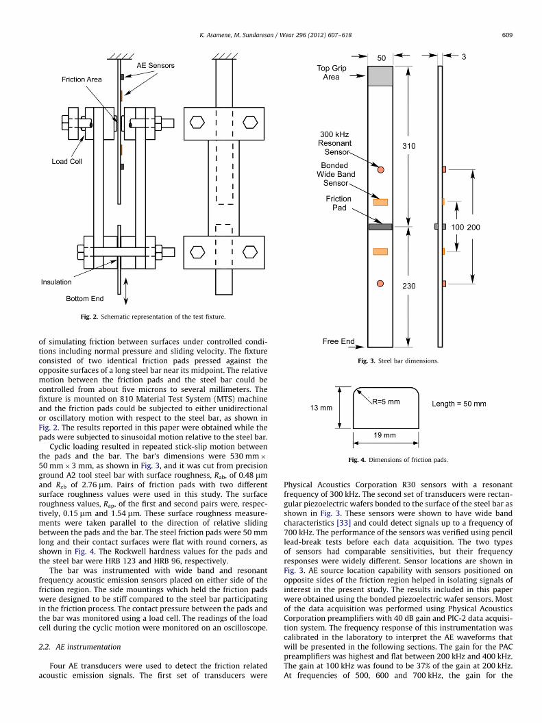
Fig. 2. Schematic representation of the test fixture.
Fig. 3. Steel bar dimensions.
Fig. 4. Dimensions of friction pads.
K. Asamene, M. Sundaresan / Wear 296 (2012) 607–618 609
of simulating friction between surfaces under controlled condi-tions including normal pressure and sliding velocity. The fixtureconsisted of two identical friction pads pressed against theopposite surfaces of a long steel bar near its midpoint. The relativemotion between the friction pads and the steel bar could becontrolled from about five microns to several millimeters. Thefixture is mounted on 810 Material Test System (MTS) machineand the friction pads could be subjected to either unidirectionalor oscillatory motion with respect to the steel bar, as shown inFig. 2. The results reported in this paper were obtained while thepads were subjected to sinusoidal motion relative to the steel bar.
Cyclic loading resulted in repeated stick-slip motion betweenthe pads and the bar. The bar’s dimensions were 530 mm�50 mm�3 mm, as shown in Fig. 3, and it was cut from precisionground A2 tool steel bar with surface roughness, Rab, of 0.48 mmand Rzb of 2.76 mm. Pairs of friction pads with two differentsurface roughness values were used in this study. The surfaceroughness values, Rap, of the first and second pairs were, respec-tively, 0.15 mm and 1.54 mm. These surface roughness measure-ments were taken parallel to the direction of relative slidingbetween the pads and the bar. The steel friction pads were 50 mmlong and their contact surfaces were flat with round corners, asshown in Fig. 4. The Rockwell hardness values for the pads andthe steel bar were HRB 123 and HRB 96, respectively.
The bar was instrumented with wide band and resonantfrequency acoustic emission sensors placed on either side of thefriction region. The side mountings which held the friction padswere designed to be stiff compared to the steel bar participatingin the friction process. The contact pressure between the pads andthe bar was monitored using a load cell. The readings of the loadcell during the cyclic motion were monitored on an oscilloscope.
2.2. AE instrumentation
Four AE transducers were used to detect the friction relatedacoustic emission signals. The first set of transducers were
Physical Acoustics Corporation R30 sensors with a resonantfrequency of 300 kHz. The second set of transducers were rectan-gular piezoelectric wafers bonded to the surface of the steel bar asshown in Fig. 3. These sensors were shown to have wide bandcharacteristics [33] and could detect signals up to a frequency of700 kHz. The performance of the sensors was verified using pencillead-break tests before each data acquisition. The two typesof sensors had comparable sensitivities, but their frequencyresponses were widely different. Sensor locations are shown inFig. 3. AE source location capability with sensors positioned onopposite sides of the friction region helped in isolating signals ofinterest in the present study. The results included in this paperwere obtained using the bonded piezoelectric wafer sensors. Mostof the data acquisition was performed using Physical AcousticsCorporation preamplifiers with 40 dB gain and PIC-2 data acquisi-tion system. The frequency response of this instrumentation wascalibrated in the laboratory to interpret the AE waveforms thatwill be presented in the following sections. The gain for the PACpreamplifiers was highest and flat between 200 kHz and 400 kHz.The gain at 100 kHz was found to be 37% of the gain at 200 kHz.At frequencies of 500, 600 and 700 kHz, the gain for the
K. Asamene, M. Sundaresan / Wear 296 (2012) 607–618610
preamplifiers was, respectively, 60, 33, and 21% of the gain at200 kHz. Physical Acoustics Corporation PIC-2 data acquisitionsystem was used to acquire the complete waveforms at a rate of5�106 samples/second. These waveforms were further processedon a personal computer. A 35 dB threshold was set for acquiringAE signals.
2.3. Test procedure
The results included in this paper correspond to sinusoidalmotion of the friction pads while the steel bar was held stationaryby gripping at its top end. The steel bar was free at the bottomend. Acoustic emission signals corresponding to different combi-nations of parameters such as surface roughness, normal pres-sure, stroke length, and velocity were recorded and examined.The range of variations in these parameters governing the frictioncondition is listed in Table 1. Table 2 lists the eight differentcombinations of friction parameters for which acoustic emissiondata were acquired. The first four tests with prefixes RS, involvedthe steel bar with relatively rough surface (Rab¼0.48 mm) andfriction pad with relatively smooth surface (Rap¼0.15 mm). Thelast four tests with prefixes RR involved the same steel bar withrelatively rough surface and friction pads of comparable rough-ness (Rap¼1.54 mm). These four tests had the same pattern ofnormal pressure, stroke length applied at the lower grip, andcyclic frequency as the first four tests. The axial load generated inthe bar depended on the contact pressure, surface roughness,axial displacement, and the stick-slip conditions prevailing at thefrictional interface. The axial load was measured by the MTS loadcell. The relative displacements of the lower grip as well as thefrictional force transferred through the friction pads during thereciprocating motion were recorded by the acoustic emission dataacquisition system.
Two sets of experiments, termed Set A and Set B, wereperformed separately to measure different parameters of interest.The contact surfaces used in these two sets had nominallyidentical roughness values. Tests on Set A were performed tocheck if measurable surface degradation was taking place duringthe tests RST1 to RST4 listed in Table 2. Surface roughness valuesat the initial condition as well as after 1000, 1300, 1600, 1900, and
Table 1Parameters for which AE signals were generated.
Friction parameter Value 1 Value 2
Contact pressure, P, MPa 2 4
Loading frequency, F, Hz 0.5 1
Axial grip displacement amplitude, A, mm 0.25 0.5
Bar surface roughness, Rab, mm 0.48 –
Friction pad roughness, Rap, mm 0.15 1.54
Table 2Combinations of parameters for which AE signals were generated.
Test Roughness,
Rap, mm
Pressure,
P, MPa
Frequency,
F, Hz
Amplitude,
A, mm
RST1 0.15 2 0.5 0.25
RST2 0.15 2 1 0.5
RST3 0.15 4 0.5 0.25
RST4 0.15 4 1 0.5
RRT1 1.54 2 0.5 0.25
RRT2 1.54 2 1 0.5
RRT3 1.54 4 0.5 0.25
RRT4 1.54 4 1 0.5
2200 cycles were measured. Both Ra and Rz values were measuredfor the pair of pads and the bar at 40 different spots distributedover the contact area. These results, presented in the next section,indicate that the surface roughness values remained essentiallyunchanged during these experiments. Furthermore, since thehardness of the bar was significantly lower than the friction pads(HRB 96 for the bar versus HRB 123 for friction pads), if measur-able wear occurred during these experiments, the bar surfacewould have been the first to indicate such changes. Hence, at theend of eight segments of cyclic loading used in Set B, the finalroughness values of the steel bar, were measured at 40 locationsand was found to be substantially same as that of its initial value.
Individual tests corresponding to each of the eight combinationsof parameters listed in Table 2 lasted only 300 cycles of reciprocat-ing motion to ensure that the surface roughness remained nearlyconstant during these tests. The pair of surfaces comprising of thebar (Rab¼0.48 mm) and smooth pad (Rap¼0.15 mm) were subjectedto 1000 cycles for initial test setup and four segments of 300 cycleseach for the four tests RST1 to RST4. Similarly the pair of surfacescomprising of the bar (Rab¼0.48 mm) and rough pad (Rap¼1.54 mm)were subjected 1000 cycles for initial test setup and four segmentsof 300 cycles each for the four tests RRT1 to RRT4. Furthermore,these surfaces were also cleaned before the fixture was reas-sembled for the next segment of the test.
3. Results and discussion
3.1. Surface roughness of contact surfaces
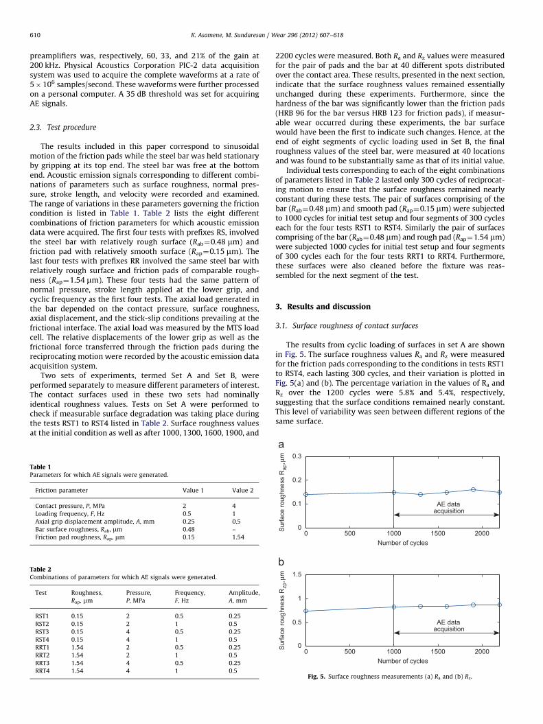
The results from cyclic loading of surfaces in set A are shownin Fig. 5. The surface roughness values Ra and Rz were measuredfor the friction pads corresponding to the conditions in tests RST1to RST4, each lasting 300 cycles, and their variation is plotted inFig. 5(a) and (b). The percentage variation in the values of Ra andRz over the 1200 cycles were 5.8% and 5.4%, respectively,suggesting that the surface conditions remained nearly constant.This level of variability was seen between different regions of thesame surface.
0 500 1000 1500 20000
0.1
0.2
0.3
Number of cycles
Sur
face
roug
hnes
s R
ap, µ
m
AE dataacquisition
0 500 1000 1500 20000
0.5
1
1.5
Number of cycles
Sur
face
roug
hnes
s R
zp, µ
m
AE dataacquisition
Fig. 5. Surface roughness measurements (a) Ra and (b) Rz.
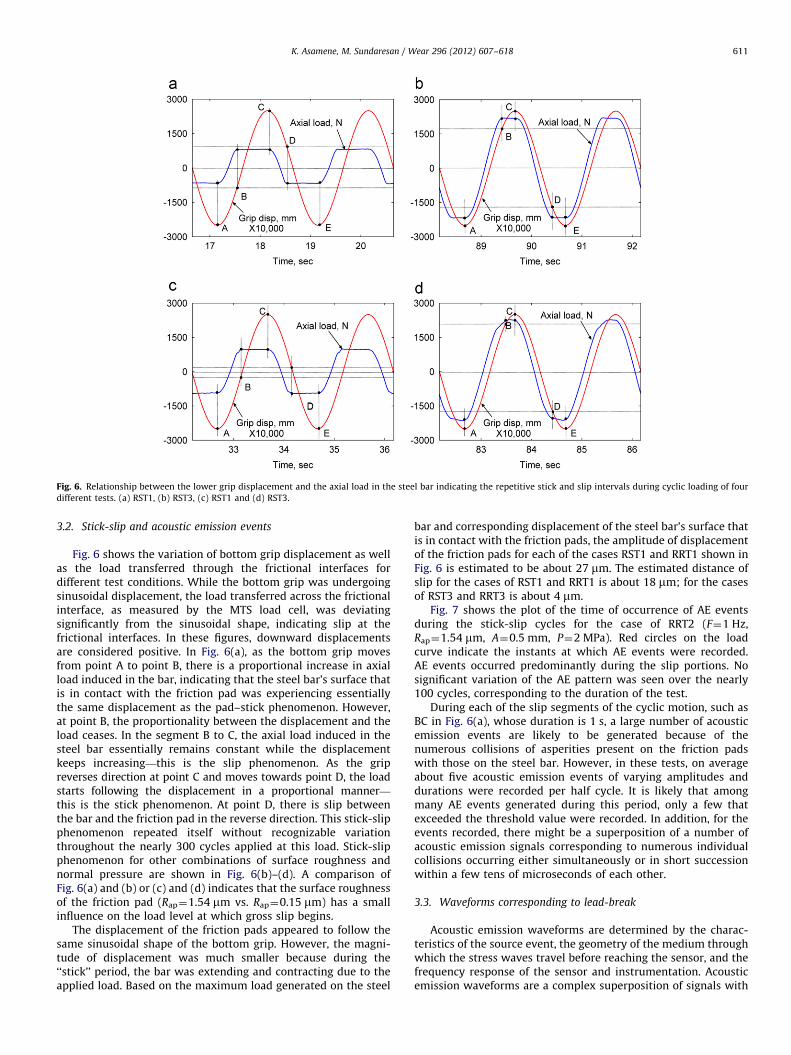
Fig. 6. Relationship between the lower grip displacement and the axial load in the steel bar indicating the repetitive stick and slip intervals during cyclic loading of four
different tests. (a) RST1, (b) RST3, (c) RST1 and (d) RST3.
K. Asamene, M. Sundaresan / Wear 296 (2012) 607–618 611
3.2. Stick-slip and acoustic emission events
Fig. 6 shows the variation of bottom grip displacement as wellas the load transferred through the frictional interfaces fordifferent test conditions. While the bottom grip was undergoingsinusoidal displacement, the load transferred across the frictionalinterface, as measured by the MTS load cell, was deviatingsignificantly from the sinusoidal shape, indicating slip at thefrictional interfaces. In these figures, downward displacementsare considered positive. In Fig. 6(a), as the bottom grip movesfrom point A to point B, there is a proportional increase in axialload induced in the bar, indicating that the steel bar’s surface thatis in contact with the friction pad was experiencing essentiallythe same displacement as the pad–stick phenomenon. However,at point B, the proportionality between the displacement and theload ceases. In the segment B to C, the axial load induced in thesteel bar essentially remains constant while the displacementkeeps increasing—this is the slip phenomenon. As the gripreverses direction at point C and moves towards point D, the loadstarts following the displacement in a proportional manner—
this is the stick phenomenon. At point D, there is slip betweenthe bar and the friction pad in the reverse direction. This stick-slipphenomenon repeated itself without recognizable variationthroughout the nearly 300 cycles applied at this load. Stick-slipphenomenon for other combinations of surface roughness andnormal pressure are shown in Fig. 6(b)–(d). A comparison ofFig. 6(a) and (b) or (c) and (d) indicates that the surface roughnessof the friction pad (Rap¼1.54 mm vs. Rap¼0.15 mm) has a smallinfluence on the load level at which gross slip begins.
The displacement of the friction pads appeared to follow thesame sinusoidal shape of the bottom grip. However, the magni-tude of displacement was much smaller because during the‘‘stick’’ period, the bar was extending and contracting due to theapplied load. Based on the maximum load generated on the steel
bar and corresponding displacement of the steel bar’s surface thatis in contact with the friction pads, the amplitude of displacementof the friction pads for each of the cases RST1 and RRT1 shown inFig. 6 is estimated to be about 27 mm. The estimated distance ofslip for the cases of RST1 and RRT1 is about 18 mm; for the casesof RST3 and RRT3 is about 4 mm.
Fig. 7 shows the plot of the time of occurrence of AE eventsduring the stick-slip cycles for the case of RRT2 (F¼1 Hz,Rap¼1.54 mm, A¼0.5 mm, P¼2 MPa). Red circles on the loadcurve indicate the instants at which AE events were recorded.AE events occurred predominantly during the slip portions. Nosignificant variation of the AE pattern was seen over the nearly100 cycles, corresponding to the duration of the test.
During each of the slip segments of the cyclic motion, such asBC in Fig. 6(a), whose duration is 1 s, a large number of acousticemission events are likely to be generated because of thenumerous collisions of asperities present on the friction padswith those on the steel bar. However, in these tests, on averageabout five acoustic emission events of varying amplitudes anddurations were recorded per half cycle. It is likely that amongmany AE events generated during this period, only a few thatexceeded the threshold value were recorded. In addition, for theevents recorded, there might be a superposition of a number ofacoustic emission signals corresponding to numerous individualcollisions occurring either simultaneously or in short successionwithin a few tens of microseconds of each other.
3.3. Waveforms corresponding to lead-break
Acoustic emission waveforms are determined by the charac-teristics of the source event, the geometry of the medium throughwhich the stress waves travel before reaching the sensor, and thefrequency response of the sensor and instrumentation. Acousticemission waveforms are a complex superposition of signals with

Fig. 7. The time of occurrence and amplitudes of AE events for RRT2. (For interpretation of the references to color in this figure caption, the reader is referred to the web
version of this article.)
8.0E-2
4.0E-2
0.0
Fig. 8. AE waveform and wavelet diagram for lead-break event.
K. Asamene, M. Sundaresan / Wear 296 (2012) 607–618612
a range of frequencies. The individual frequency components arenot readily recognizable from the waveforms. However, thewavelet diagrams indicate the presence of different frequencycomponents as well as their arrival times. Even though all thefrequency components are generated at the same time at thesource, they travel with different velocities and hence arrive atdifferent times at the sensor.
In order to have a baseline for interpreting the friction relatedwaveforms, the signal characteristics corresponding to a lead-breaktest are first presented in Fig. 8. This comparison is helpful in isolatingthe features related to the source events. Here both the waveform andthe wavelet diagram are included. AGU Vallen wavelet software is
used to obtain the wavelet diagrams [34]. A lead-break test iscommonly used to verify the acoustic emission test setup and isassumed to simulate discrete events such as an incremental crackgrowth. A 2 mm long 0.5 mm diameter HB pencil lead was broken atthe center of the steel bar’s friction area to generate the waveform.These waveforms had peak amplitude of nearly 2 V and started withlarge initial amplitude, after which there was a rapid drop inamplitude. There is a second segment after about 110 ms, due tothe reflections from the ends of the bar. In particular, there is a periodof very little signal amplitude between the initial signal and thereflections. The different frequency components of the signal andtheir arrival times are clearly seen in the wavelet diagram.

K. Asamene, M. Sundaresan / Wear 296 (2012) 607–618 613
3.4. Friction related waveforms
Nearly 70% of the AE events recorded during these testsoriginated from the region of frictional contact between the frictionpads and the steel bar. Signals originating from other locationswere excluded from this analysis based on the source location.
Fig. 9. AE waveform and wavelet diagram fo
Fig. 10. AE waveform and wavelet d
Fig. 9 shows a typical waveform corresponding to friction relatedAE event obtained during the slip phase of test RST4 (Rap¼0.15 mm,P¼4 MPa, A¼0.5 mm, F¼1 Hz). Most waveforms are characterizedby large amplitude at the start of the waveform followed bygradually decreasing amplitude, which extended to a little morethan 500 ms. Furthermore, as in lead-break tests, the arrival of the
5.0E-4
2.5E-4
0.0
r friction related event from test RST4.
5.0E-4
2.5E-4
0.0
iagram for crack growth event.
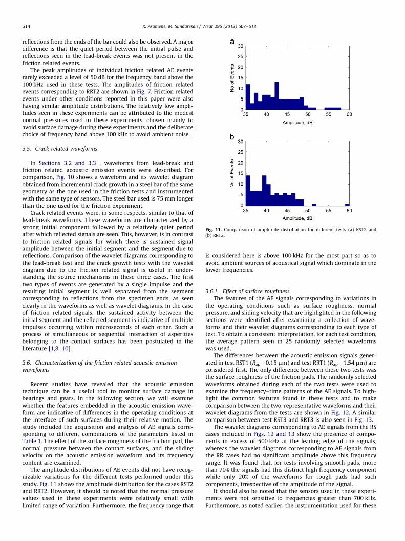
Fig. 11. Comparison of amplitude distribution for different tests (a) RST2 and
(b) RRT2.
K. Asamene, M. Sundaresan / Wear 296 (2012) 607–618614
reflections from the ends of the bar could also be observed. A majordifference is that the quiet period between the initial pulse andreflections seen in the lead-break events was not present in thefriction related events.
The peak amplitudes of individual friction related AE eventsrarely exceeded a level of 50 dB for the frequency band above the100 kHz used in these tests. The amplitudes of friction relatedevents corresponding to RRT2 are shown in Fig. 7. Friction relatedevents under other conditions reported in this paper were alsohaving similar amplitude distributions. The relatively low ampli-tudes seen in these experiments can be attributed to the modestnormal pressures used in these experiments, chosen mainly toavoid surface damage during these experiments and the deliberatechoice of frequency band above 100 kHz to avoid ambient noise.
3.5. Crack related waveforms
In Sections 3.2 and 3.3 , waveforms from lead-break andfriction related acoustic emission events were described. Forcomparison, Fig. 10 shows a waveform and its wavelet diagramobtained from incremental crack growth in a steel bar of the samegeometry as the one used in the friction tests and instrumentedwith the same type of sensors. The steel bar used is 75 mm longerthan the one used for the friction experiment.
Crack related events were, in some respects, similar to that oflead-break waveforms. These waveforms are characterized by astrong initial component followed by a relatively quiet periodafter which reflected signals are seen. This, however, is in contrastto friction related signals for which there is sustained signalamplitude between the initial segment and the segment due toreflections. Comparison of the wavelet diagrams corresponding tothe lead-break test and the crack growth tests with the waveletdiagram due to the friction related signal is useful in under-standing the source mechanisms in these three cases. The firsttwo types of events are generated by a single impulse and theresulting initial segment is well separated from the segmentcorresponding to reflections from the specimen ends, as seenclearly in the waveforms as well as wavelet diagrams. In the caseof friction related signals, the sustained activity between theinitial segment and the reflected segment is indicative of multipleimpulses occurring within microseconds of each other. Such aprocess of simultaneous or sequential interaction of asperitiesbelonging to the contact surfaces has been postulated in theliterature [1,8–10].
3.6. Characterization of the friction related acoustic emission
waveforms
Recent studies have revealed that the acoustic emissiontechnique can be a useful tool to monitor surface damage inbearings and gears. In the following section, we will examinewhether the features embedded in the acoustic emission wave-form are indicative of differences in the operating conditions atthe interface of such surfaces during their relative motion. Thestudy included the acquisition and analysis of AE signals corre-sponding to different combinations of the parameters listed inTable 1. The effect of the surface roughness of the friction pad, thenormal pressure between the contact surfaces, and the slidingvelocity on the acoustic emission waveform and its frequencycontent are examined.
The amplitude distributions of AE events did not have recog-nizable variations for the different tests performed under thisstudy. Fig. 11 shows the amplitude distribution for the cases RST2and RRT2. However, it should be noted that the normal pressurevalues used in these experiments were relatively small withlimited range of variation. Furthermore, the frequency range that
is considered here is above 100 kHz for the most part so as toavoid ambient sources of acoustical signal which dominate in thelower frequencies.
3.6.1. Effect of surface roughness
The features of the AE signals corresponding to variations inthe operating conditions such as surface roughness, normalpressure, and sliding velocity that are highlighted in the followingsections were identified after examining a collection of wave-forms and their wavelet diagrams corresponding to each type oftest. To obtain a consistent interpretation, for each test condition,the average pattern seen in 25 randomly selected waveformswas used.
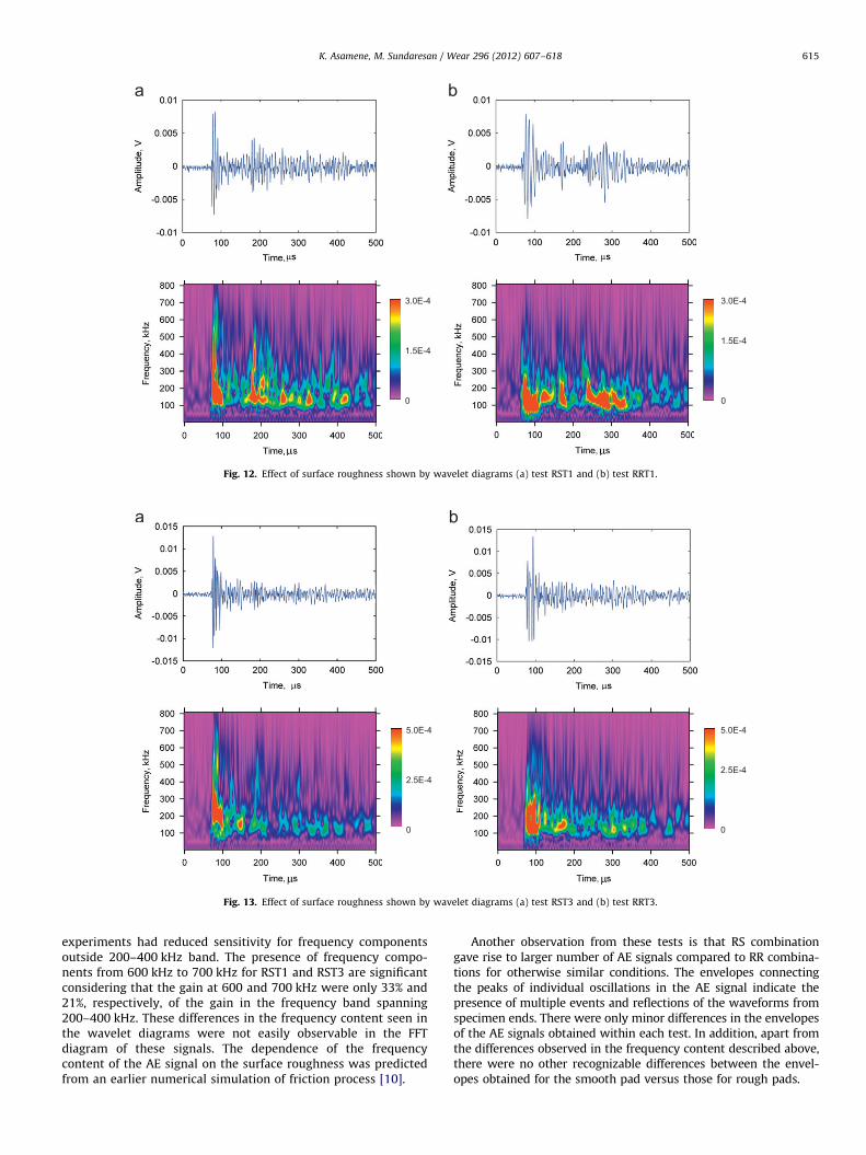
The differences between the acoustic emission signals gener-ated in test RST1 (Rap¼0.15 mm) and test RRT1 (Rap¼1.54 mm) areconsidered first. The only difference between these two tests wasthe surface roughness of the friction pads. The randomly selectedwaveforms obtained during each of the two tests were used toexamine the frequency–time patterns of the AE signals. To high-light the common features found in these tests and to makecomparison between the two, representative waveforms and theirwavelet diagrams from the tests are shown in Fig. 12. A similarcomparison between test RST3 and RRT3 is also seen in Fig. 13.
The wavelet diagrams corresponding to AE signals from the RScases included in Figs. 12 and 13 show the presence of compo-nents in excess of 500 kHz at the leading edge of the signals,whereas the wavelet diagrams corresponding to AE signals fromthe RR cases had no significant amplitude above this frequencyrange. It was found that, for tests involving smooth pads, morethan 70% the signals had this distinct high frequency componentwhile only 20% of the waveforms for rough pads had suchcomponents, irrespective of the amplitude of the signal.
It should also be noted that the sensors used in these experi-ments were not sensitive to frequencies greater than 700 kHz.Furthermore, as noted earlier, the instrumentation used for these
3.0E-4
1.5E-4
0
3.0E-4
1.5E-4
0
Fig. 12. Effect of surface roughness shown by wavelet diagrams (a) test RST1 and (b) test RRT1.
5.0E-4
2.5E-4
0
5.0E-4
2.5E-4
0
Fig. 13. Effect of surface roughness shown by wavelet diagrams (a) test RST3 and (b) test RRT3.
K. Asamene, M. Sundaresan / Wear 296 (2012) 607–618 615
experiments had reduced sensitivity for frequency componentsoutside 200–400 kHz band. The presence of frequency compo-nents from 600 kHz to 700 kHz for RST1 and RST3 are significantconsidering that the gain at 600 and 700 kHz were only 33% and21%, respectively, of the gain in the frequency band spanning200–400 kHz. These differences in the frequency content seen inthe wavelet diagrams were not easily observable in the FFTdiagram of these signals. The dependence of the frequencycontent of the AE signal on the surface roughness was predictedfrom an earlier numerical simulation of friction process [10].
Another observation from these tests is that RS combinationgave rise to larger number of AE signals compared to RR combina-tions for otherwise similar conditions. The envelopes connectingthe peaks of individual oscillations in the AE signal indicate thepresence of multiple events and reflections of the waveforms fromspecimen ends. There were only minor differences in the envelopesof the AE signals obtained within each test. In addition, apart fromthe differences observed in the frequency content described above,there were no other recognizable differences between the envel-opes obtained for the smooth pad versus those for rough pads.
K. Asamene, M. Sundaresan / Wear 296 (2012) 607–618616
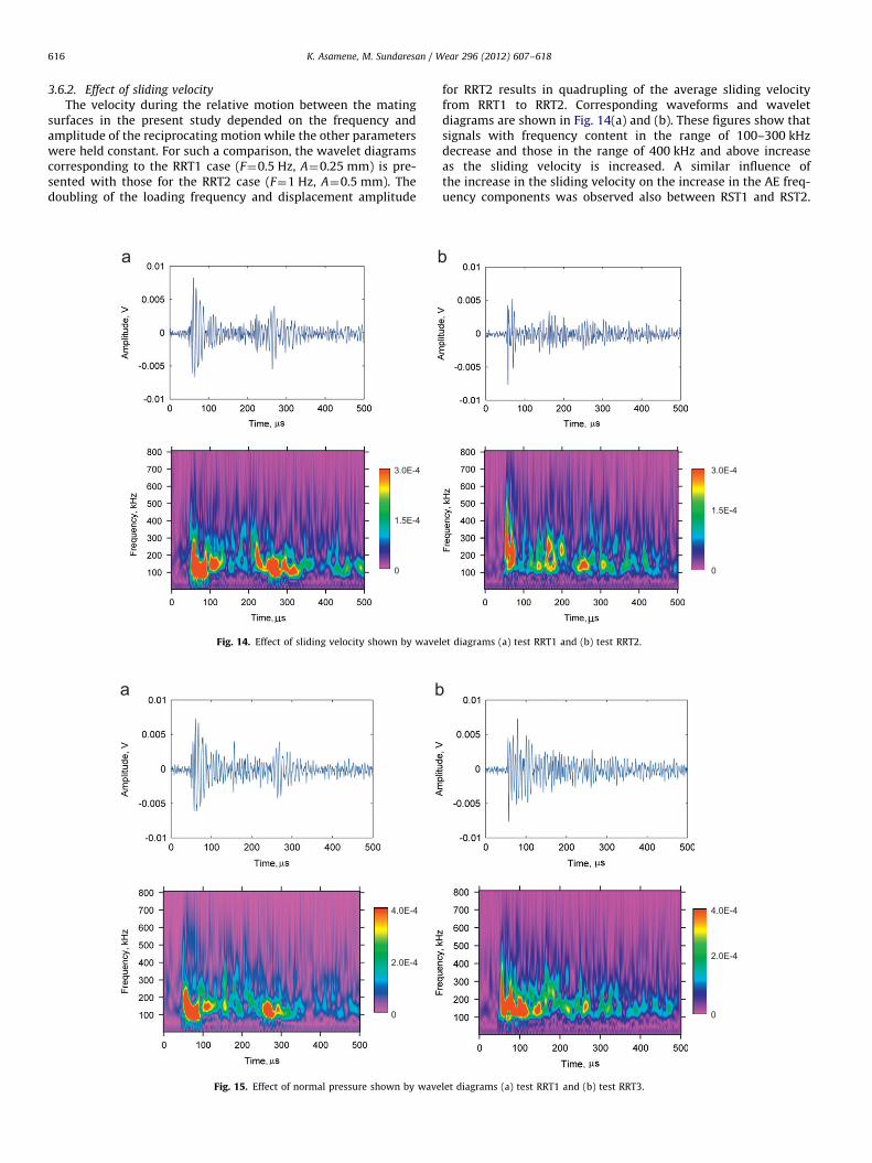
3.6.2. Effect of sliding velocity
The velocity during the relative motion between the matingsurfaces in the present study depended on the frequency andamplitude of the reciprocating motion while the other parameterswere held constant. For such a comparison, the wavelet diagramscorresponding to the RRT1 case (F¼0.5 Hz, A¼0.25 mm) is pre-sented with those for the RRT2 case (F¼1 Hz, A¼0.5 mm). Thedoubling of the loading frequency and displacement amplitude
3.0E-4
1.5E-4
0
Fig. 14. Effect of sliding velocity shown by wave
4.0E-4
2.0E-4
0
Fig. 15. Effect of normal pressure shown by wave
for RRT2 results in quadrupling of the average sliding velocityfrom RRT1 to RRT2. Corresponding waveforms and waveletdiagrams are shown in Fig. 14(a) and (b). These figures show thatsignals with frequency content in the range of 100–300 kHzdecrease and those in the range of 400 kHz and above increaseas the sliding velocity is increased. A similar influence ofthe increase in the sliding velocity on the increase in the AE freq-uency components was observed also between RST1 and RST2.
3.0E-4
1.5E-4
0
let diagrams (a) test RRT1 and (b) test RRT2.
4.0E-4
2.0E-4
0
let diagrams (a) test RRT1 and (b) test RRT3.
K. Asamene, M. Sundaresan / Wear 296 (2012) 607–618 617
These tendencies were seen in a majority of the signals collected.However, there were exceptions to these trends in a few of the AEsignals. These trends were also predicted in the infinite elementsimulation of friction related AE signals in the earlier study [10].
3.6.3. Effect of normal pressure
The influence of the normal pressure on the AE signal isexamined by comparing the results for RRT1 for which the normalpressure was 2 MPa with those of RRT3 for which the normalpressure was 4 MPa. These results are shown in Fig. 15(a) and (b).In these cases, the other parameters had identical values. Themain difference between the two waveforms was in the intensityof the AE signal between the first arrival and the reflections fromthe specimen ends. For the case of RRT3, there was significantlygreater signal strength before the arrival of the reflection. Athigher normal pressures, greater interference between the aspe-rities in the surfaces in contact is likely to be present. As a result, agreater number of asperities are likely to participate in generatingthe AE signals. Changes in the normal pressure did not seem toaffect the frequency contents of the signals.
3.7. Friction parameters and AE signal characteristics
By limiting the number of cycles used for each of these tests,surface damage and accumulation of wear particles were kept at aminimum. As mentioned earlier the surfaces were cleaned inbetween the tests to remove loose particles. Hence, the majorityof AE events from these tests are attributed to the interaction ofasperities.
Acoustic emission instrumentation used in these experimentsused a frequency range of 100 kHz–700 kHz. This frequency rangewas selected to avoid saturation of the amplifier by lower frequencycomponents and to minimize signals from ambient noise. In thesetests, variations of the tribological parameters such as surfaceroughness, sliding velocity, and normal pressure were only verymodest. The results presented in this section show that even forthese modest changes in the friction conditions, clearly recognizabledifferences in the features of the AE waveforms were present. Inaddition, the friction related acoustic emission signals were distin-guishable from signals from other sources such as crack growth.
4. Summary and conclusion
In this paper, we explore if the parameters controlling theinteraction of two contacting surfaces during the friction processare recognizable in the acoustic emission waveforms and if thosefeatures could be clearly identified. A test fixture to simulate thereciprocating motion between two flat surfaces in contact wasdeveloped. In this fixture, the parameters such as normal pres-sure, surface roughness, and sliding velocity could be closelycontrolled. Acoustic emission signals generated by the frictionprocess for different combinations of surface roughness, normalpressure, and the velocity of sliding were evaluated.
Friction related waveforms, in general, depicted patterns thatwere consistent with multiple asperity interactions during slip.The basic features of friction related AE signals were distinct fromthose of other AE sources. Clear and systematic changes in thesignal characteristics that could be related to the parametersoperating at the frictional interface were found. Acoustic emissionfrequency components well in excess of 700 kHz were generatedby the friction process. Frequency component of the signals wasfound to increase as the roughness of one of the surfaces wasdecreased. In addition, the frequency content was also found toincrease with the increase in sliding velocity. AE signal durationappears to increase with an increase in normal pressure.
AE behavior of the friction process observed during theseexperiments was mostly in agreement with the earlier numericalpredictions [10]. The results obtained in this research indicatethat acoustic emission technique can be a sensitive tool formonitoring the conditions of the tribological surfaces.
Acknowledgment
The authors would like to thank Army Research Office fundingfor proposal number 60562-RT-REP and NASA Grant #NNX09AV08A for the financial support. The authors would alsolike to thank Mr. Gene Warwick for preparing the test fixtures andmembers of ISM lab at North Carolina A&T State University fortheir assistance.
References
[1] V. Baranov, E. Kudryavtsev, G. Sarychev, V. Schavelin, Acoustic Emission inFriction, Elsevier Science, Great Britain, 2007.
[2] D. Dornfeld, C. Handy, Slip detection using acoustic emission signal analysis,Proceedings of the IEEE International Conference on Robotics and Automa-tion 4 (1987) 1868–1875.
[3] T. Jibiki, M. Shima, H. Akita, M. Tamura, A basic study of friction noise causedby fretting, Wear 251 (2001) 1492–1503.
[4] C. Ferrer, F. Salas, Discrete acoustic emission waves during stick-slip frictionbetween steel samples, Tribology International 43 (2010) 1–6.
[5] H. Abdelounis, A.L. Bot, J. Perret-Liaudet, H. Zahouani, An experimental studyon roughness noise of dry rough flat surfaces, Wear 268 (2010) 335–354.
[6] A. Hase, M. Wada, H. Mishina, The relationship between acoustic emissionsand wear particles for repeated dry rubbing, Wear 265 (2008) 831–839.
[7] T. Hisakado, T. Warashina, Relationship between friction and wear propertiesand acoustic emission characteristics: iron pin on hardened bearing steeldisk, Wear 216 (1998) 1–7.
[8] Y. Fan, F. Gu, A. Ball, Modeling acoustic emissions generated by slidingfriction, Wear 268 (2010) 811–815.
[9] V. Baranov, E. Kudryavtsev, G. Sarychev, Modeling of the parameters ofacoustic emission under sliding friction of solids, Wear 202 (1997) 125–133.
[10] Md.T. Alam, M. Sundaresan, Characterization of fretting related acousticemission signals, in: Proceedings of the SPIE 7650, San Diego, 2010.
[11] C. James, S.Y. Li, Acoustic emission analysis for bearing condition monitoring,Wear 185 (1995) 67–74.
[12] S. Al-Dossary, R.I.R. Hamzah, D. Mba, Observations of changes in acousticemission waveform for varying seeded defect sizes in a rolling elementbearing, Applied Acoustics 70 (2009) 58–81.
[13] K.R. Al-Balushi, B. Samanta, Gear fault diagnosis using energy-based featuresof acoustic emission signals, Proceedings of the Institution of MechanicalEngineers. Part I: Journal of Systems and Control Engineering 216 (2002)249–263.
[14] T. Toutountzakis, C.K. Tan, D. Mba, Application of acoustic emission to seededgear fault detection, NDT & E International 38 (2005) 27–36.
[15] T. Jayakumar, C.K. Mukhopadhyay, S. Venugopal, S.L. Mannan, B. Raj,A review of the application of acoustic emission techniques for monitoringforming and grinding processes, Journal of Materials Processing Technology159 (2005) 48–61.
[16] J. Meriaux, M. Boinet, S. Fouvry, J.C. Lenain, Identification of fretting fatiguecrack propagation mechanisms using acoustic emission, Tribology Interna-tional 43 (2010) 2166–2174.
[17] T. Skare, P. Thilderkvist, J.E. Stahl, Monitoring of friction processes by themeans of acoustic emission measurements—deep drawing of sheet metal,Journal of Materials Processing Technology 80–81 (1998) 263–272.
[18] J. Sun, R.J.K. Wood, L. Wang, I. Care, H.E.G. Powrie, Wear monitoring ofbearing steel using electrostatic and acoustic emission techniques, Wear 259(2005) 1482–1489.
[19] B. Kilundu, X. Chiementin, J. Duez, D. Mba, Cyclostationarity of acousticemissions for monitoring bearing defects, Mechanical Systems and SignalProcessing 25 (2011) 2061–2072.
[20] G. Kalogiannakis, J. Quintelier, P. De Baets, J. Degrieck, D. Van Hemelrijck,Identification of wear mechanisms of glass/polyester composites by means ofacoustic emission, Wear 264 (2008) 235–244.
[21] J. Miettinen, V. Siekkinen, Case Study Acoustic emission in monitoring slidingcontact behavior, Wear 181-183 (1995) 897–900.
[22] P.L. Menezes, S.V. Kishore, Kailas, Influence of surface texture and roughnessparameters on friction and transfer layer formation during sliding ofaluminum pin on steel plate, Wear 267 (2009) 1534–1549.
[23] S. Philippon, G. Sutter, A. Molinari, An experimental study of friction at highsliding velocities, Wear 257 (2004) 777–784.
[24] F. Van de Velde, P. De Baets, The relation between friction force and relativespeed during the slip-phase of a stick-slip cycle, Wear 219 (1998) 220–226.

K. Asamene, M. Sundaresan / Wear 296 (2012) 607–618618
[25] B. Bhushan, Contact mechanics of rough surfaces in tribology: multipleasperity contact, Tribology letters 4 (1998) 1–35.
[26] I.J. Ford, Roughness effect on friction for multi-asperity contact betweensurfaces, Journal of Physics D—Applied Physics 26 (1993) 2219–2225.
[27] A. Hutson, T. Nicholas, R. Goodman, Fretting fatigue of Ti–6Al–4V under flat-on-flat contact, International Journal of Fatigue 21 (1999) 663–669.
[28] A. Hutson, T. Nicholas, R. John, Fretting fatigue crack analysis in Ti–6Al–4V,International Journal of Fatigue 27 (2005) 1582–1589.
[29] B. Bhushan, Handbook of micro/nano tribology, Springer, USA, 1999.[30] P.J. Blau, Friction science and technology: from concepts to applications, CRC
Press, 2009.
[31] G.W. Stachowiak, A.W. Batchelor, G.B. Stachowiak, Experimental methods intribology, Elsevier Science, The Netherlands, 2004.
[32] K. Asamene, W. Williams, M. Sundaresan, Experimental analysis of frettingrelated acoustic emission signals, in: Proceedings of the SPIE 7981, San Diego,2011.
[33] M. Jacques, P. Desai, F. Salih, M. Sundaresan, Evaluation of bonded piezo-electric AE sensor for structural health monitoring, in: Proceedings of theSPIE 6935, San Diego, 2008.
[34] M.A. Hamstad, An Illustrated overview of the use and value of a wavelettransformation to acoustic emission technology, Oct 2011, /www.vallen.de/wavelet/index.htmS.