Embed Size (px)
Citation preview

Analysis of electric power andenergy systems
Lecture 6: High Voltage DC transmission
Bertrand Corné[email protected]
1 / 53

What will we learn today?Why HVDC systems are used and how they are implemented (focus on LCC)
What are LCCs
What are thyristors
Basic control principles of LCC HVDC
How to insert a point-to-point HVDC line in a power �ow analysis
Note that I have mainly taken material from former course "ELEC0445 - HVDCgrids", but it follows the logic of Chapter 7 of Ned Mohan's book.
1 / 53
Overview of HVDC applicationsIntroduction of former course "ELEC0445 - HVDC grids".
2 / 53

Principle of HVDC links
HVDC links embedded in AC systems
Rely on converters :
recti�er: from AC to DC
inverter: from DC to AC
3 / 53
Historical perspective
At the beginning (end of 19th century) : two struggling parties
�rst generators producing Direct Current (DC) - Gramme, Edison
�rst generators producing Alternating Current (AC) - Ferranti, Tesla
Have a look at the video "War of the currents"
the AC system won :
possibility to increase and lower the voltage thanks to the transformer transmission ofhigher powers possible
creation of a rotating �eld easy with three-phase AC windings
Dif�culty to raise the DC voltage impossibility to transmit large powers with DC
limitation of the power of early converters : a few kW only
dif�culty of interrupting a DC current.
Revival of DC technology in the ‘50s
⇒
⇒
4 / 53

Historical perspective (cont’d)
Advances in power electronics : converters can carry larger currents throughhigher voltages higher power ratings transmission applications possible
1882 : Marcel Deprez (France) and Oskar Von Miller (Germany, AEG) designthe �rst transmission link between a DC source and a DC load:
See also René Thury's work: https://en.wikipedia.org/wiki/Ren%C3%A9_Thury
mid ‘30s : mercury-arc valve recti�ers made available. They open the way toHVDC transmission link projects
1945 : �rst commercial project of HVDC transmission in Germany. Notcommissioned and moved to USSR (Moscow-Kashira) in 1950:
, with buried cables
Nekrasov, A. M., & Posse, A. V. (1959). Work done in the Soviet Union on high-voltage long-distance dc power transmission. Transactions of the American Institute of ElectricalEngineers. Part III: Power Apparatus and Systems, 78(3), 515-521.
1954 : �rst commercial HVDC submarine installation : from Gotland island toSweden:
Up to the mid ‘60s, due to its higher cost, HVDC was favoured only where ACmet operational dif�culties, e.g. sea crossing
⇒ ⇒
15kW 2 kV 56.3 km
60MW 200 kV 115 km
20MW 100 kV 98 km
5 / 53

Historical perspective (cont’d)
late ‘60s : advent of high power thyristor-based valve converters
1975 : 1st long-distance HVDC transmission using thyristor valve converters :Cahora Bassa in Mozambique: , with overhead
line
thyristor ratings have grown up to kV and kA (per thyristor)
late ‘90s : high power transistor-based components become available : IGBT,MOSFET
development of Voltage Source Converters. Among other advantages, theyallow controlling both the active and the reactive powers at the AC terminalsof an HVDC link.
1920MW 533 kV 1420 km
V = 9 I = 4
6 / 53

Paci�c DC inter-tie along West coast ofUSA : 1360 km 3100 MW 500 kV
Cahora-Bassa line in Mozambique :1420 km 1920 MW 533 kV
Hydro-Québec DC line : 1018 km 2000MW 450 kV
First application : Power transmission over long distances
Long AC lines require reactive power compensation / voltage support and fordistances larger than 600-800 km, HVDC is more economical
Examples :
±
±
±
7 / 53

initial investment is higher for DC(due to converters) but
with increasing distance, reactivepower compensation is requiredfor an AC line
break-even distance 600-800 km
comparison of towers : sametransmission capacity of 3 GW, a)735 kV AC b) 500 kV DC
smaller Right-of-Way for DCcorridor
reduced footprint
Smaller investment costs
±
8 / 53

Lower losses, higher thermal capacity
At a similar voltage level (RMS phase-to-phase vs. DC pole-to-ground) :
a DC line can transmit more than twice the power of an AC line
with about half the losses of an AC line.
9 / 53

AC cables have large capacitance.Maximal acceptable length : 50-70km.
For larger distances, HVDC is theonly (reasonable) solution
Examples from Europe :
NorNed link between Norway andThe Netherlands (2008)\ 580 km 700
MW 450 kV (LCC type)
Nemo link between Belgium and UK
(2019)\ 140 km 1000 MW 400 kV(VSC type)
Connections of off-shore wind parksin North Sea to the continentalEuropean grid
Source ENTSOe (www.entsoe.eu)
Second application : submarine power transmission
±
±
10 / 53

Third application : DC link in AC grid, for power �ow control
power �ows in AC lines cannot be controlled directly
determined by line impedances, obeying Ohm and Kirchhoff laws
partially controllable by phase shifting transformers
power �ows in HVDC links can be controlled directly (through the controllersof converters). This can be used :
to limit “loop �ows” and overloading of AC lines
to make the link participate in energy tradings.
Examples :
ALEGrO (Aachen Liège Electric Grid Overlay) project of HVDC link between Belgium andGermany (2020): 100 km (49 in Belgium) 1000 MW buried cable
France - Spain DC interconnection : 65 km buried XLPE cable 320 kV DC 2000 MW±
11 / 53

Can reverse power �ow in 150milliseconds (!)
Investment cost : 700 M€
France - Spain DC interconnection
12 / 53
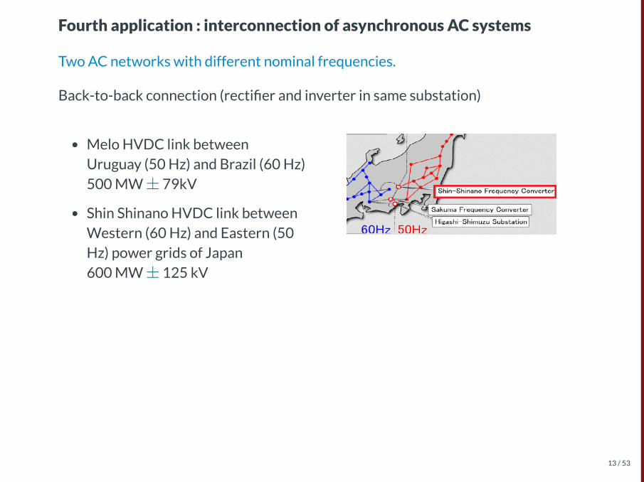
Melo HVDC link betweenUruguay (50 Hz) and Brazil (60 Hz)500 MW 79kV
Shin Shinano HVDC link betweenWestern (60 Hz) and Eastern (50Hz) power grids of Japan 600 MW 125 kV
Fourth application : interconnection of asynchronous AC systems
Two AC networks with different nominal frequencies.
Back-to-back connection (recti�er and inverter in same substation)
±
±
13 / 53

Highgate back-to-back HVDC linkbetween Québec and Vermont200 MW 57 kV
McNeil HVDC link between Alberta andSaskatchewan 150 MW 42 kV
Two AC networks with identical nominal frequency but different frequencies (notinterconnected for size reasons)
± ±
14 / 53

A few systems are in operation todaywith proven technology
example : the Sardinia-Corsica-Italylink (SACOI) 3 terminals. The 2-terminal Italy-Sardinia link wasinitially built, and the Corsicaterminal installed at a later stage
more elaborate control scheme thanfor a two-terminal link
Another application : collect powerfrom off-shore wind parks locatedalong a DC link between two on-shoreterminals
Fifth application : Multiterminal DC grids
Radial DC link with AC/DC converter(s) connected at intermediate points
15 / 53

Meshed DC grids
still at research level
typical targeted application : (i) collect power from off-shore wind parks, and(ii) allow power exchanges between on-shore grids
main technological challenges :
identi�cation of faults in DC grid (to isolate only the faulted branch)
DC circuit breaker to interrupt the DC fault current
16 / 53

Line Commuted Converters (LCC)
large power ratings
large harmonics �lters
requires a strong enough AC grid
active power is controlled
always consumes reactive power
cannot be used as off-shoreterminal to collect wind power
cheaper (but VSC is a fast evolvingtechnology)
less commutation losses than VSC
but possible commutation failure
Voltage Source Converters (VSC)
lower power ratings (but fastgrowing technology)
less harmonic �lters needed
can operate with a weak AC grid
active and reactive powers can becontrolled
can be used as off-shore terminal tocollect wind power
black start capability
Two technologies
17 / 53

LCC technology
based on thyristors, used as switches closed with delay
thyristor commutation synchronized with grid voltage (hence the term “linecommutated”)
also referred to as “Current Source Converter” or “classic HVDC”
DC current cannot be reversed (due to thyristors). Hence, power is reversedby reversing the DC voltage polarity.
18 / 53
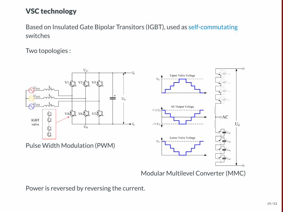
Pulse Width Modulation (PWM)
Modular Multilevel Converter (MMC)
VSC technology
Based on Insulated Gate Bipolar Transitors (IGBT), used as self-commutatingswitches
Two topologies :
Power is reversed by reversing the current.
19 / 53

Components of an LCC HVDC linkExtract of chapter 1 of former course "ELEC0445 - HVDC grids".
20 / 53
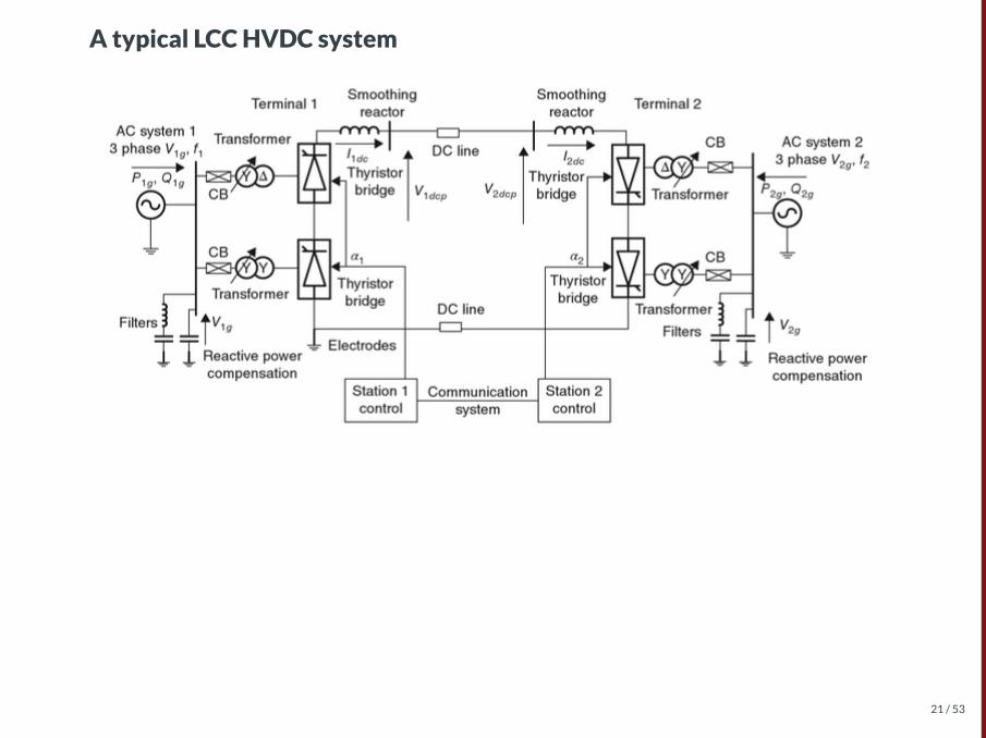
A typical LCC HVDC system
21 / 53

Converters
one converter at each terminal : the sending power end acts as a recti�er, thereceiving power end as an inverter
each converter includes one or several thyristor bridges
each bridge is made up of 6 thyristor valves
each thyristor valve contains hundreds of individual thyristors
22 / 53

Converter transformers
most generally equipped with load tap changers. The transformer ratios areadjusted to optimize the HVDC link operation
designed to operate with high harmonic currents
generally more expensive than typical transmission transformers of the same rating
23 / 53

Smoothing reactors on the DC side
aimed at limiting the DC current variations
designed considering response to DC faults and commutation failures
typical values of inductance : 0.1 to 0.5 H
air-core, natural air cooling type
24 / 53
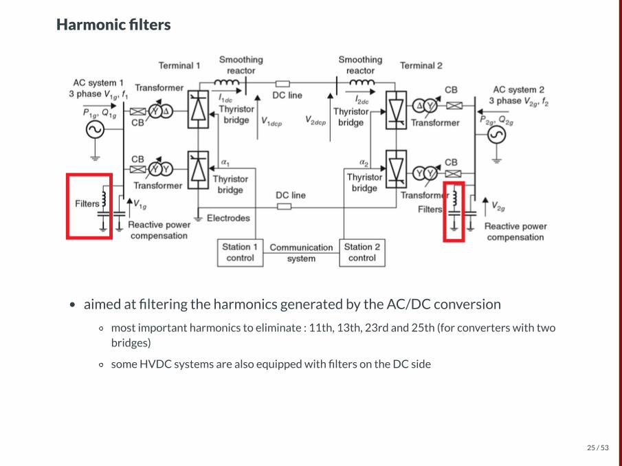
Harmonic �lters
aimed at �ltering the harmonics generated by the AC/DC conversion
most important harmonics to eliminate : 11th, 13th, 23rd and 25th (for converters with twobridges)
some HVDC systems are also equipped with �lters on the DC side
25 / 53

Reactive power compensation
the converters consume reactive power (around 60% of power rating)
that reactive power varies with the active power level
a large part of the reactive compensation comes from the �lter banks
the remaining part is supplied by switchable capacitor banks
26 / 53

Control and communication systems
each terminal has a control system with multiple hierarchical layers : control ofresp. the DC current, the DC voltage, the thyristors, etc.
a dedicated communication link is needed between both terminals to optimizesystem operation
27 / 53

Thyristor valvesA summary of chapter 2 of former course "ELEC0445 - HVDC grids".
28 / 53

Three junctions , , equivalent to two bipolar transistors
assume and inject
both transistors remain in saturationeven if is suppressed
The thyristor
Essential component of HVDC valves in the LCC technology
operates as a controllable diode
can have high power ratings : up to 8.5 kV, 4500 A capability
is robust and ef�cient.
Four-layer, three-terminal device.
pn J1 J2 J3
V > 0AK IG
IG
29 / 53

Usage of a thyristor
A thyristor can be used as a controllable bistable switch
the control is performed by injecting a current at the gate input
the thyristor is ON and conducts when it is forward biased and the gate receives a currentpulse
the thyristor keeps on conducting as long as it is forward biased
the thyristor is turned OFF when the anode current falls below the holding current thresholdIH or when it is reverse biased
the thyristor remains in blocking mode until it is triggered by a new gate pulse current
the process of turning OFF is called commutation
when commutating, the thyristor cannot immediately withstand a forward voltage; it shouldremain reverse biased for a minimum time, otherwise commutation failure can take place.
30 / 53

Modes of operation of the thyristor
Three modes of operation depending on :
the sign of the anode cathode voltage
whether a current is injected at the gate terminal
A reverse voltage is applied.
Junction is in forward bias mode
junctions and are in reverse bias mode
the thyristor acts as a diode in reverse bias mode; it is in off-state
breakdown occurs when is more negative than the reverse breakdown
voltage . Most often this is associated with junction
in HVDC applications, the breakdown mode must be avoided since it can leadto material destruction.
hence, thyristors with high values must be used, and measures taken to
limit the avalanche current.
− vAK
IG
v < 0AK
J2
J1 J3
vAK
VBR J1
∣V ∣BR
31 / 53

Modes of operation of the thyristor (...)
A forward voltage is applied
Junctions and are forward in bias mode
junction is in reverse bias mode
the thyristor behaves as a diode in reverse bias mode; it is in off-state
breakdown occurs when is larger than the forward breakdown voltage of
junction
v > 0AK
J1 J3
J2
vAK
J2
32 / 53
Modes of operation of the thyristor (...)
A forward voltage is applied and a current is injected.
the current injection results in an avalanche process
“as if” layer would become of -type. Hence, the thyristor behaves as a
diode in forward bias mode : it switches to on-state
the thyristor resistance is dramatically reduced (from to )
the larger , the smaller the value of needed to initiate the avalanche.
v > 0AK Ig
p2 n pn
10 Ω6 10 Ω−1
IG vAK
33 / 53

Operation of the thyristor in on-state
once the anode current reaches , the latching curent, the thyristor
switches to on-state
once the thyristor is in on-state, the gate current can be removed
the gate current is usually a short pulse lasting 10-50 s
if falls below , the holding curent, the thyristor switches to off-state.
commutation is not instantaneous -> dynamics -> and care must be taken withapplied currents and voltages -> snubber circuits
i IL
μ
i IH
34 / 53
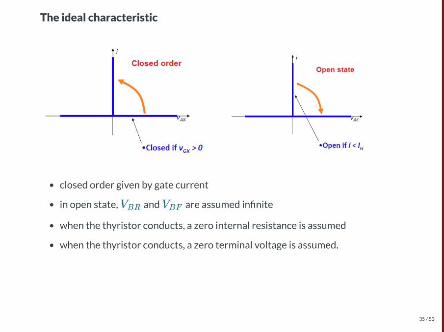
The ideal characteristic
closed order given by gate current
in open state, and are assumed in�nite
when the thyristor conducts, a zero internal resistance is assumed
when the thyristor conducts, a zero terminal voltage is assumed.
VBR VBF
35 / 53

Thyristor modules (i.e. thyristor +snubber circuit + voltage balancingcircuits) are associated in series toform a thyristor valve.
Objective : reach the HVDC link
voltage rating :
thyristor : up to 5 to 9 kV
HVDC link : 500 to 800 kV
A 2000A, 250 kV high voltage directcurrent (HVDC) thyristor valve atManitoba Hydro's Henday converterstation. Photo taken April 2001. Source:Wikipedia.
Thyristor valves
36 / 53
Operation of the LCC lineA summary of chapter 3 of former course "ELEC0445 - High Voltage Direct
Current grids".
37 / 53

Diode based recti�er
Without �ltering, we already have a relatively good recti�cation.
38 / 53

To get a more constant current, we use smoothing reactors in series. The bigger ,
the more constant the current.
Hence we suppose is constant, and the currents in the 3 phases on the AC side
look like
Note that in practice, as there are inductors in the system, currents cannot varyabruptly, and there is a commutation overlap (two of the three diodes conductingsimultaneously), hence an angle and a voltage reduction. We'll neglect this in the
sequel (to keep it simple), but this is important in practice.
Ld
Id
μ
39 / 53

The thyristor-based 6-pulse recti er with no ignition delay
In this case Thyristor = Diode (natural conduction)
Average direct voltage = integral of line voltage over a period of length π/3
V = U = 1.35Ud0π
3 2
40 / 53

The ignition can be delayed up to
for instance : switching from valve1 to valve 3 is possible as long as
.
After that, valve 3 is in reverseblocking mode.
Waveforms in a recti�ed multiplethyristor circuit controlling an ACcurrent. Red trace: load (output) voltageBlue trace: trigger voltage. Source:Wikipidia (Thyristor)
With an ignition delay
]
α
α = 180∘
v < va b
41 / 53
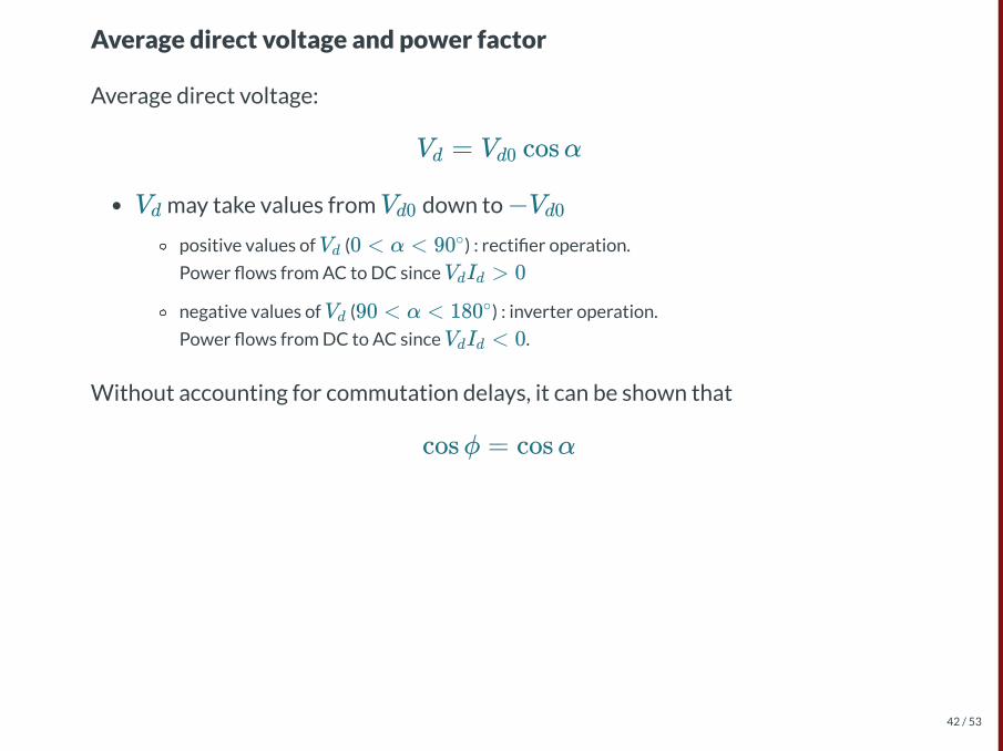
Average direct voltage and power factor
Average direct voltage:
may take values from down to
positive values of ( ) : recti�er operation.
Power �ows from AC to DC since
negative values of ( ) : inverter operation.
Power �ows from DC to AC since .
Without accounting for commutation delays, it can be shown that
V = V cosαd d0
Vd Vd0 −Vd0
Vd 0 < α < 90∘
V I > 0d d
Vd 90 < α < 180∘
V I < 0d d
cosϕ = cosα
42 / 53

Control
43 / 53
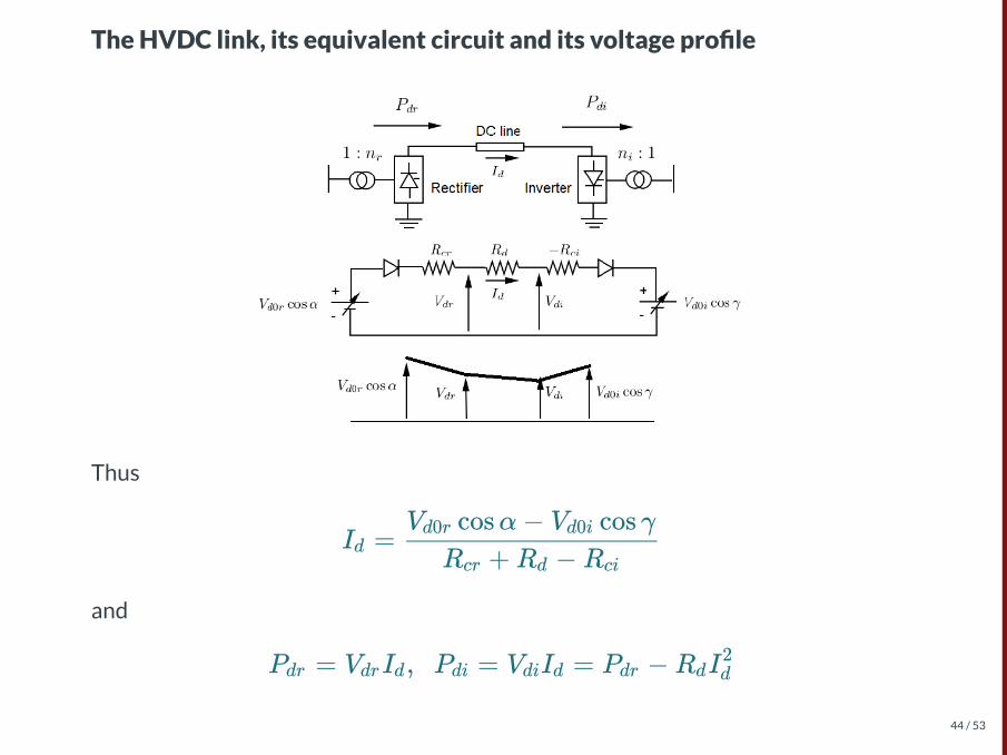
The HVDC link, its equivalent circuit and its voltage pro�le
Thus
and
I =dR +R −Rcr d ci
V cosα− V cos γd0r d0i
P = V I , P = V I = P −R Idr dr d di di d dr d d2
44 / 53
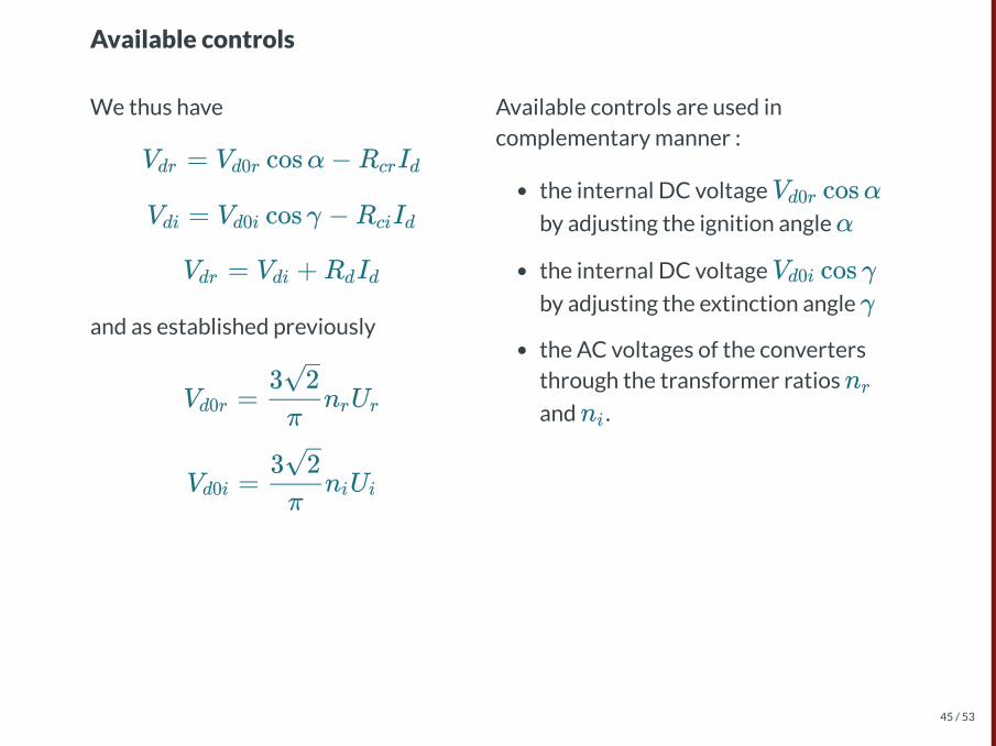
We thus have
and as established previously
Available controls are used incomplementary manner :
the internal DC voltage
by adjusting the ignition angle
the internal DC voltage
by adjusting the extinction angle
the AC voltages of the convertersthrough the transformer ratios
and .
Available controls
V = V cosα−R Idr d0r cr d
V = V cos γ −R Idi d0i ci d
V = V +R Idr di d d
V = n Ud0rπ
3 2r r
V = n Ud0iπ
3 2i i
V cosαd0r
α
V cos γd0i
γ
nr
ni
45 / 53

Remarks
Attention must be paid to :
avoiding too low a current (unstable commutation)
avoiding too high a current (overload of valves)
having a stable HVDC link operation in spite of variations of AC voltages.
The power (or ) can be controlled instead of the current .
Id
Id
Pdr Pdi Id
46 / 53

Control principle
Overall principle :
the regulations of resp. and are performed by the terminals separately
this does not require fast exchange of information between both terminals
only when the respective roles of the recti�er and the inverter change
Under normal operation :
the recti�er maintains a Constant Current (CC) mode
the inverter maintains Constant Extinction Angle (CEA) mode.
Vd Id
Id
γ
47 / 53

Ideal steady-state characteristics:
Recti�er characteristic : constant
Inverter characteristic : from previous equations
generally, is slightly larger than and the characteristic has a small
negative slope
Operating state : point E at the intersection of the two characteristics
V − I
I =d
V = V cos γ + (R −R )Idr d0i d ci d
Rci Rd
48 / 53

HVDC in the power �ow analysis
49 / 53

A DC line is modelled as twogenerators in the load�ow:
The active power at the from side isde�ned by the parameters in thedcline table.
The active power at the to side isequal to the active power on thefrom side minus the losses of the DCline.
The voltage control with reactivepower works just as described forthe generator model. Maximum andMinimum reactive power limits areconsidered in the OPF, and in the PFif it is run with enforce_q_lims=True.
A simple implementation in panda power for point to point HVDC
From https://pandapower.readthedocs.io/en/v2.4.0/elements/dcline.html:
50 / 53
More advanced implementation (OPF setting)
Hotz, M., & Utschick, W. (2019). hynet: An optimal power �ow framework forhybrid AC/DC power systems. IEEE Transactions on Power Systems, 35(2), 1036-1047.
"While the modeling of DC grids, where DC lines and cables are considered viatheir equivalent series resistance, resembles that of AC grids and is ratherstraightforward, the modeling of VSCs is more intricate. Elaborate models for VSCstations comprise a transformer, �lter, phase reactor, and converter. While theformer three can be considered via equivalent -models, the converter is modeled
as a lossy transfer of active power between the AC and DC side of the converterwith the provision of reactive power on the AC side (...). Many recent works modelthe converter losses as a quadratic function of the converter current (...) In terms ofoperating limits, the most elaborate characterizations include a converter currentlimit as well as constraints that restrict the provision of reactive power based onthe coupling of the AC- and DC-side voltage (...). As a consequence of the signi�cantincrease in model complexity compared to AC systems, the mathematicalformulation and parameterization of the OPF problem for hybrid AC/DC powersystems is intricate and extensive."
π
51 / 53

Other implementations examples
Braunagel, Kraft, Whysong - 1976 - Inclusion of DC converter and transmissionequations directly in a newton power �ow.
Bondhala, U., & Sarkar, V. (2011). Power Flow Studies of an AC-DC TransmissionSystem (Doctoral dissertation, Indian Institute of Technology Hyderabad).
52 / 53

ReferencesMohan, Ned. Electric power systems: a �rst course. John Wiley & Sons, 2012.
Course notes of ELEC0445 by Pr. Thierry Van Cutsem and al.
L. Thurner, A. Scheidler, F. Schäfer et al, pandapower - an Open Source PythonTool for Convenient Modeling, Analysis and Optimization of Electric PowerSystems, in IEEE Transactions on Power Systems, vol. 33, no. 6, pp. 6510-6521,Nov. 2018.
53 / 53

The end.
53 / 53