Embed Size (px)
Citation preview
Journal of Multidisciplinary Engineering Science and Technology (JMEST)
ISSN: 2458-9403
Vol. 3 Issue 10, October - 2016
www.jmest.org
JMESTN42351820 5720
Analysis of Doubly-Fed Induction Generator driven by Wind Turbine
Eng.mohammed fathy ahmed, Dr.Salama Abo-Zaid, assis.Prof.Hamdy Abd El-Halim, Prof.Mahmoud Elwany
Dept. of Electrical Engineering Al-Azhar University
Cairo, Egypt [email protected]
Abstract- The doubly-fed induction generator
driven by a Wind Turbine has recently received a great attention from the industrial and scientific communities, due to easily produces a fixed frequency voltage from the stator windings when the rotor is driven at variable speed and the excitation power electronics converter feeding the rotor windings can be rated at a fraction of the nominal power of the generator. This paper provides the design and analysis of doubly-fed induction generator (DFIG) for wind energy conversion systems (WECS), this model is proposed for the seamless operation. The control on Grid side converter (GSC) and Rotor side converter (RSC) through detailed simulation will be studied on a 1.5-MW wind turbine.
Keywords—Doubly fed induction generator (DFIG), Grid side converter(GSC), Rotor side converter (RSC), wind turbine (WT).
I. INTRODUCTION (HEADING 1)
The doubly fed induction generator (DFIG) based wind turbines are nowadays more widely used in large wind farms. The main reasons for the increasing number of DFIGs connected to the electric grid are low converter power rating and ability to supply power at constant voltage and frequency while the rotor speed varies. The DFIG concept also provides possibility to control the overall system power factor. The majority of a large capacity machines (>1 MW) are available for General Electric-Wind. The power electronic converters enable control over the generator operating characteristics such as speed and reactive power. [1] The wind turbine can operate in one of two ways. The first is to have a relatively fixed rotational speed, in which an increase in wind speed can slightly increase the rotor speed above the synchronous speed and thus varying the slip. This is based purely on the torque-speed relationship of an induction machine. A speed controller is used to vary the pitch of the wind turbine blades during high wind speeds to reduce the power intake and protect the wind turbine. By optimizing a term called tip speed ratio we can optimize the ratio of wind speed to rotor speed:
ƛ =Vtip
Vwind (1)
where Vtip is the velocity of the blade tip and Vwind is
the wind velocity. The tip velocity can be calculated from:
Vtip = ῼ. r (2)
Where ῼ is the mechanical speed of the wind turbine
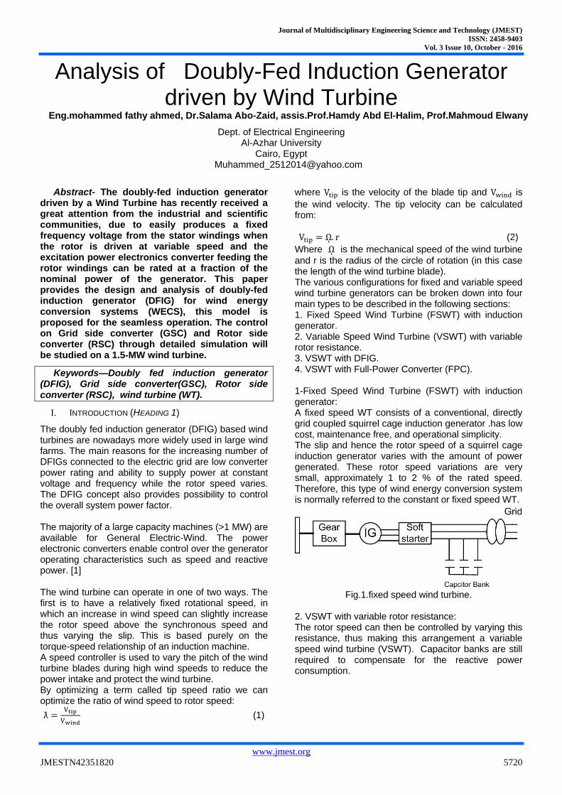
and r is the radius of the circle of rotation (in this case the length of the wind turbine blade). The various configurations for fixed and variable speed wind turbine generators can be broken down into four main types to be described in the following sections: 1. Fixed Speed Wind Turbine (FSWT) with induction generator. 2. Variable Speed Wind Turbine (VSWT) with variable rotor resistance. 3. VSWT with DFIG. 4. VSWT with Full-Power Converter (FPC). 1-Fixed Speed Wind Turbine (FSWT) with induction generator: A fixed speed WT consists of a conventional, directly grid coupled squirrel cage induction generator .has low cost, maintenance free, and operational simplicity. The slip and hence the rotor speed of a squirrel cage induction generator varies with the amount of power generated. These rotor speed variations are very small, approximately 1 to 2 % of the rated speed. Therefore, this type of wind energy conversion system is normally referred to the constant or fixed speed WT.
Fig.1.fixed speed wind turbine.
2. VSWT with variable rotor resistance: The rotor speed can then be controlled by varying this resistance, thus making this arrangement a variable speed wind turbine (VSWT). Capacitor banks are still required to compensate for the reactive power consumption.
Journal of Multidisciplinary Engineering Science and Technology (JMEST)
ISSN: 2458-9403
Vol. 3 Issue 10, October - 2016
www.jmest.org
JMESTN42351820 5721
Fig.2.Variable speed wind turbine with variable rotor
resistance. 3. VSWT with Doubly-Fed Induction Generator: In the doubly fed induction generator, a back-to-back voltage source converter feeds the three-phase rotor winding. In this way, the mechanical and electrical rotor frequencies are decoupled, and the electrical stator and rotor frequencies can be matched independently on the mechanical rotor speed. The power electronics devices used in doubly-fed induction generators: this power is supplied to or from the generator rotor windings, which is typically about 30% of the generator rated power. Consequently, the power electronics devices in variable-speed wind turbines using doubly-fed induction generators typically need only to be about 30% of the size of the power electronics devices used for comparatively sized three-phase synchronous generators, This reduces the cost of the power electronics devices, as well as the power losses in these device.[2]
Fig .3. Variable speed wind turbine with doubly fed
induction generator.
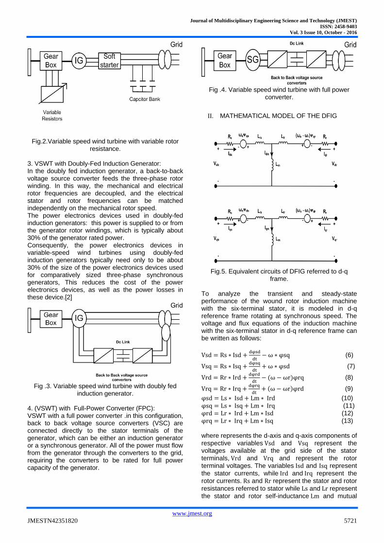
4. (VSWT) with Full-Power Converter (FPC): VSWT with a full power converter .in this configuration, back to back voltage source converters (VSC) are connected directly to the stator terminals of the generator, which can be either an induction generator or a synchronous generator. All of the power must flow from the generator through the converters to the grid, requiring the converters to be rated for full power capacity of the generator.
Fig .4. Variable speed wind turbine with full power
converter.
II. MATHEMATICAL MODEL OF THE DFIG
Fig.5. Equivalent circuits of DFIG referred to d-q
frame. To analyze the transient and steady-state performance of the wound rotor induction machine with the six-terminal stator, it is modeled in d-q reference frame rotating at synchronous speed. The voltage and flux equations of the induction machine with the six-terminal stator in d-q reference frame can be written as follows:
Vsd = Rs ∗ Isd +dφsd
dt− ω ∗ φsq (6)
Vsq = Rs ∗ Isq +dφsq
dt+ ω ∗ φsd (7)
Vrd = Rr ∗ Ird +dφrd
dt− (ω − ωr)φrq (8)
Vrq = Rr ∗ Irq +dφrq
dt+ (ω − ωr)φrd (9)
φsd = Ls ∗ Isd + Lm ∗ Ird (10)
φsq = Ls ∗ Isq + Lm ∗ Irq (11) φrd = Lr ∗ Ird + Lm ∗ Isd (12) φrq = Lr ∗ Irq + Lm ∗ Isq (13) where represents the d-axis and q-axis components of
respective variables Vsd and Vsq represent the voltages available at the grid side of the stator
terminals, Vrd and Vrq and represent the rotor terminal voltages. The variables Isd and Isq represent
the stator currents, while Ird and Irq represent the rotor currents. Rs and Rr represent the stator and rotor
resistances referred to stator while Ls and Lr represent the stator and rotor self-inductance Lm and mutual
Journal of Multidisciplinary Engineering Science and Technology (JMEST)
ISSN: 2458-9403
Vol. 3 Issue 10, October - 2016
www.jmest.org
JMESTN42351820 5722
inductance referred to stator, respectively. ω is supply
angular frequency while ωr is the rotor angular frequency in electrical radians per second. The electromagnetic torque can be written as: Te = Isqφsd − Isdφsq (14)
The q axis is aligned with the stator voltage. This implies that vsd = 0 and vsq = vs . This approach is useful for doubly fed machines where the control is performed by a means of the rotor voltage. The stator voltage is the grid voltage, which is approximately constant in a stable grid. The rotor voltage is referred to the same frame. It consists in general of two non- zero d–q components. This d–q frame orientation decouples the active power from reactive power and they can be con- trolled independently. The stator active power Ps and reactive power Qs are expressed as follows:
ps=VsqIsq (15)
Qs = VsqIdq (16)
Fig. 6. Choice of d–q frame orientation.
III. WIND TURBINE MODEL
A. The aerodynamic model with DFIG
The mechanical power output that a turbine can produce is given by:
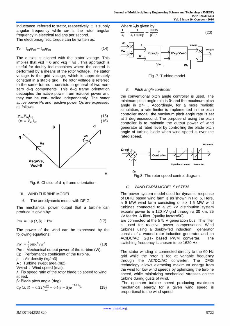
Pm = Cp (λ, β) · Pw (17) The power of the wind can be expressed by the following equations:
Pw =1
2ρπR2Vw3 (18)
Pm : Mechanical output power of the turbine (W). Cp : Performance coefficient of the turbine.
ρ : Air density (kg/m3) A : Turbine swept area (m2). Vwind : Wind speed (m/s). λ :Tip speed ratio of the rotor blade tip speed to wind speed. β: Blade pitch angle (deg).
Cp (λ, β) = 0.22(116
λi− 0.4 β − 5)e
−12.5λi
⁄ (19)
Where λiis given by: 1
λi=
1
λi+0.08β−
0.035
β3+1 (20)
Fig .7. Turbine model.
B. Pitch angle controller.
the conventional pitch angle controller is used. The minimum pitch angle min is 0◦ and the maximum pitch angle is 27◦ . Accordingly, for a more realistic simulation, a rate limiter is implemented in the pitch controller model. the maximum pitch angle rate is set at 2 degrees/second. The purpose of using the pitch controller is to maintain the output power of wind generator at rated level by controlling the blade pitch angle of turbine blade when wind speed is over the rated speed.
Fig.8. The rotor speed control diagram.
C. WIND FARM MODEL SYSTEM
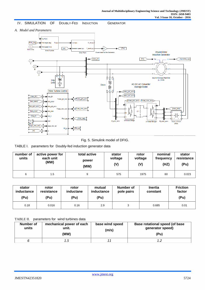
The power system model used for dynamic response of DFIG based wind farm is as shown in Fig. 5. Here, a 9 MW wind farm consisting of six 1:5 MW wind turbines connected to a 25 kV distribution system exports power to a 120 kV grid through a 30 km, 25 kV feeder. A filter (quality factor=50) are connected at the 575 V generation bus. This filter is used for reactive power compensation. Wind turbines using a doubly-fed induction generator consist of a wound rotor induction generator and an AC/DC/AC IGBT- based PWM converter. The switching frequency is chosen to be 1620 Hz. The stator winding is connected directly to the 60 Hz grid while the rotor is fed at variable frequency through the AC/DC/AC converter. The DFIG technology allows extracting maximum energy from the wind for low wind speeds by optimizing the turbine speed, while minimizing mechanical stresses on the turbine during gusts of wind. The optimum turbine speed producing maximum mechanical energy for a given wind speed is proportional to the wind speed.
Journal of Multidisciplinary Engineering Science and Technology (JMEST)
ISSN: 2458-9403
Vol. 3 Issue 10, October - 2016
www.jmest.org
JMESTN42351820 5723
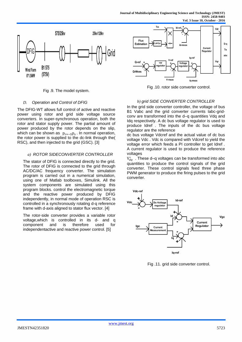
Fig .9. The model system.
D. Operation and Control of DFIG
The DFIG-WT allows full control of active and reactive power using rotor and grid side voltage source converters. In super-synchronous operation, both the rotor and stator supply power. The partial amount of power produced by the rotor depends on the slip, which can be shown as pr=−Sps . In normal operation, the rotor power is supplied to the dc-link through the( RSC), and then injected to the grid (GSC). [3]
a) ROTOR SIDECONVERTER CONTROLLER
The stator of DFIG is connected directly to the grid. The rotor of DFIG is connected to the grid through AC/DC/AC frequency converter. The simulation program is carried out in a numerical simulation, using one of Matlab toolboxes, Simulink. All the system components are simulated using this program blocks. control the electromagnetic torque and the reactive power produced by DFIG independently, in normal mode of operation RSC is controlled in a synchronously rotating d-q reference frame with d-axis aligned to stator flux vector. [4]
The rotor-side converter provides a variable rotor voltage,which is controlled in its d- and q component and is therefore used for independentactive and reactive power control. [5]
Fig .10. rotor side converter control.
b) grid SIDE CONVERTER CONTROLLER
In the grid side converter controller, the voltage of bus B1 Vabc and the grid converter currents Iabc-grid-conv are transformed into the d–q quantities Vdq and Idq respectively. A dc bus voltage regulator is used to produce Idref . The inputs of the dc bus voltage regulator are the reference dc bus voltage Vdcref and the actual value of dc bus voltage Vdc . Vdc is compared with Vdcref to yield the voltage error which feeds a PI controller to get Idref . A current regulator is used to produce the reference voltages
V𝑑𝑞∗ . These d–q voltages can be transformed into abc
quantities to produce the control signals of the grid converter. These control signals feed three phase PWM generator to produce the firing pulses to the grid converter.
Fig .11. grid side converter control.
Journal of Multidisciplinary Engineering Science and Technology (JMEST)
ISSN: 2458-9403
Vol. 3 Issue 10, October - 2016
www.jmest.org
JMESTN42351820 5724
IV. SIMULATION OF DOUBLY-FED INDUCTION GENERATOR
A. Model and Parameters
Fig. 5. Simulink model of DFIG.
TABLE I. parameters for Doubly-fed induction generator data
number of units
active power for each unit
(MW)
total active
power
(MW)
stator voltage
(V)
rotor voltage
(V)
nominal frequency
(HZ)
stator resistance
(Pu)
6 1.5 9 575 1975 60 0.023
stator inductance
)Pu(
rotor resistance
)Pu(
rotor inductane
)Pu(
mutual inductance
)Pu(
Number of pole pairs
Inertia constant
Friction factor
)Pu(
0.18 0.016 0.16 2.9 3 0.685 0.01
TABLE II. parameters for wind turbines data
Number of units
mechanical power of each unit.
(MW)
base wind speed
(m/s)
Base rotational speed (of base generator speed)
)Pu(
6 1.5 11 1.2
Journal of Multidisciplinary Engineering Science and Technology (JMEST)
ISSN: 2458-9403
Vol. 3 Issue 10, October - 2016
www.jmest.org
JMESTN42351820 5725
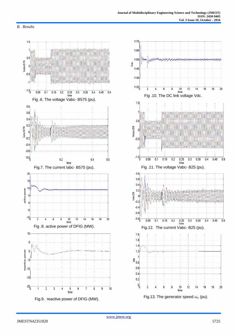
B. Results
Fig .6. The voltage Vabc- B575 (pu).
Fig.7. The current Iabc- B575 (pu).
Fig .8. active power of DFIG (MW).
Fig.9. reactive power of DFIG (MW).
Fig .10. The DC link voltage Vdc.
Fig .11. The voltage Vabc- B25 (pu).
Fig.12. The current Vabc- B25 (pu).
Fig.13. The generator speed ωr (pu).
Journal of Multidisciplinary Engineering Science and Technology (JMEST)
ISSN: 2458-9403
Vol. 3 Issue 10, October - 2016
www.jmest.org
JMESTN42351820 5726
The result show the performance of the DFIG as the voltage and current after the DFIG and the voltage and current at bus 25kv. The voltage is stable at (1pu).the result also show the active power of the wind farm(9MW).and reactive power of the DFIG (0MW). the result also show the DFIG speed (1.2pu) and the dc voltage (1150v).
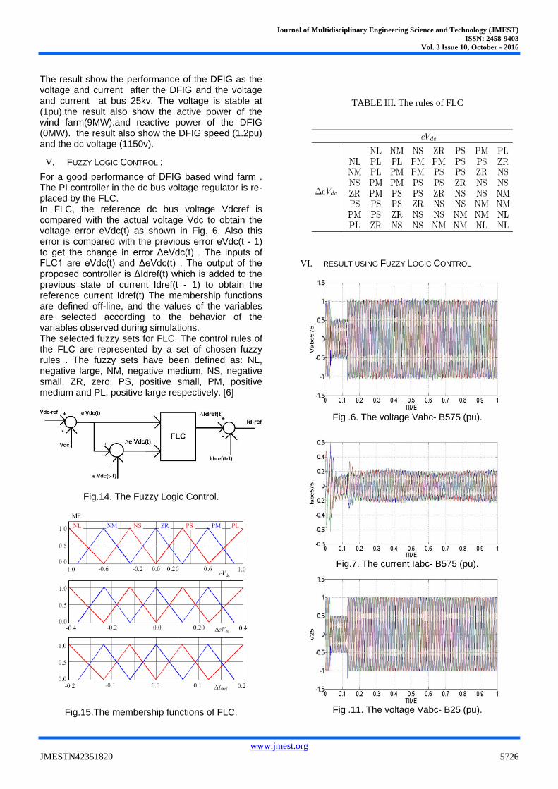
V. FUZZY LOGIC CONTROL :
For a good performance of DFIG based wind farm . The PI controller in the dc bus voltage regulator is re- placed by the FLC. In FLC, the reference dc bus voltage Vdcref is compared with the actual voltage Vdc to obtain the voltage error eVdc(t) as shown in Fig. 6. Also this error is compared with the previous error eVdc(t - 1) to get the change in error ΔeVdc(t) . The inputs of FLC1 are eVdc(t) and ΔeVdc(t) . The output of the proposed controller is ΔIdref(t) which is added to the previous state of current Idref(t - 1) to obtain the reference current Idref(t) The membership functions are defined off-line, and the values of the variables are selected according to the behavior of the variables observed during simulations. The selected fuzzy sets for FLC. The control rules of the FLC are represented by a set of chosen fuzzy rules . The fuzzy sets have been defined as: NL, negative large, NM, negative medium, NS, negative small, ZR, zero, PS, positive small, PM, positive medium and PL, positive large respectively. [6]
Fig.14. The Fuzzy Logic Control.
Fig.15.The membership functions of FLC.
TABLE III. The rules of FLC
VI. RESULT USING FUZZY LOGIC CONTROL
Fig .6. The voltage Vabc- B575 (pu).
Fig.7. The current Iabc- B575 (pu).
Fig .11. The voltage Vabc- B25 (pu).
Journal of Multidisciplinary Engineering Science and Technology (JMEST)
ISSN: 2458-9403
Vol. 3 Issue 10, October - 2016
www.jmest.org
JMESTN42351820 5727
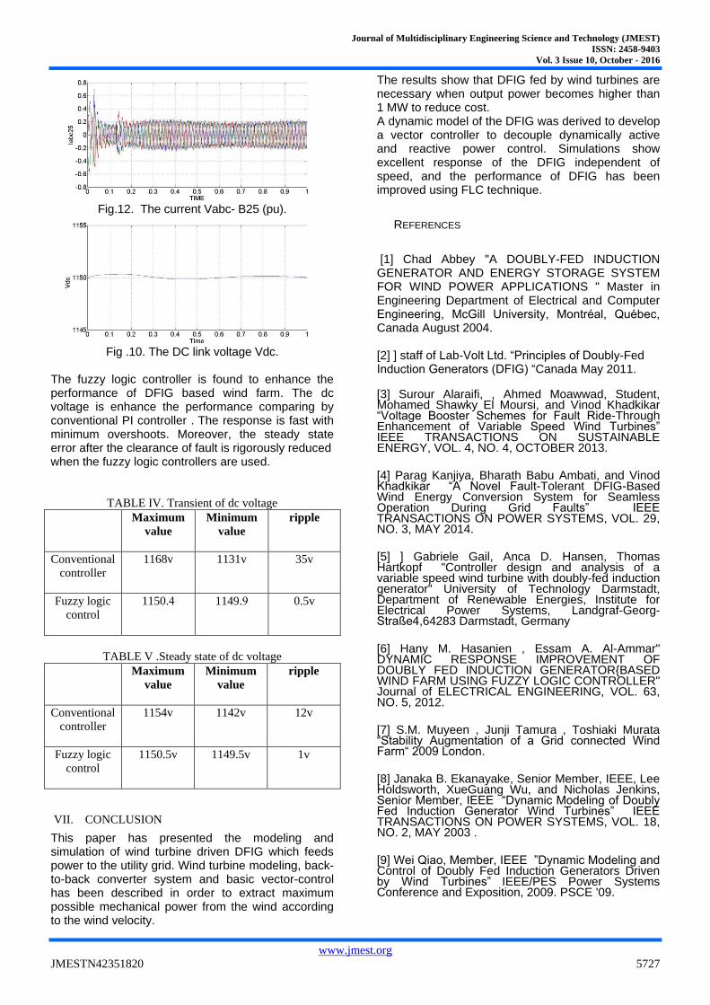
Fig.12. The current Vabc- B25 (pu).
Fig .10. The DC link voltage Vdc.
The fuzzy logic controller is found to enhance the performance of DFIG based wind farm. The dc voltage is enhance the performance comparing by conventional PI controller . The response is fast with minimum overshoots. Moreover, the steady state error after the clearance of fault is rigorously reduced when the fuzzy logic controllers are used.
TABLE IV. Transient of dc voltage
Maximum
value
Minimum
value
ripple
Conventional
controller
1168v
1131v
35v
Fuzzy logic
control
1150.4
1149.9
0.5v
TABLE V .Steady state of dc voltage
Maximum
value
Minimum
value
ripple
Conventional
controller
1154v 1142v 12v
Fuzzy logic
control
1150.5v 1149.5v 1v
VII. CONCLUSION
This paper has presented the modeling and simulation of wind turbine driven DFIG which feeds power to the utility grid. Wind turbine modeling, back-to-back converter system and basic vector-control has been described in order to extract maximum possible mechanical power from the wind according to the wind velocity.
The results show that DFIG fed by wind turbines are necessary when output power becomes higher than 1 MW to reduce cost. A dynamic model of the DFIG was derived to develop a vector controller to decouple dynamically active and reactive power control. Simulations show excellent response of the DFIG independent of speed, and the performance of DFIG has been improved using FLC technique.
REFERENCES
[1] Chad Abbey "A DOUBLY-FED INDUCTION GENERATOR AND ENERGY STORAGE SYSTEM FOR WIND POWER APPLICATIONS " Master in Engineering Department of Electrical and Computer Engineering, McGill University, Montréal, Québec, Canada August 2004.
[2] ] staff of Lab-Volt Ltd. “Principles of Doubly-Fed Induction Generators (DFIG) “Canada May 2011.
[3] Surour Alaraifi, , Ahmed Moawwad, Student, Mohamed Shawky El Moursi, and Vinod Khadkikar “Voltage Booster Schemes for Fault Ride-Through Enhancement of Variable Speed Wind Turbines” IEEE TRANSACTIONS ON SUSTAINABLE ENERGY, VOL. 4, NO. 4, OCTOBER 2013.
[4] Parag Kanjiya, Bharath Babu Ambati, and Vinod Khadkikar “A Novel Fault-Tolerant DFIG-Based Wind Energy Conversion System for Seamless Operation During Grid Faults” IEEE TRANSACTIONS ON POWER SYSTEMS, VOL. 29, NO. 3, MAY 2014.
[5] ] Gabriele Gail, Anca D. Hansen, Thomas Hartkopf "Controller design and analysis of a variable speed wind turbine with doubly-fed induction generator" University of Technology Darmstadt, Department of Renewable Energies, Institute for Electrical Power Systems, Landgraf-Georg-Straße4,64283 Darmstadt, Germany
[6] Hany M. Hasanien , Essam A. Al-Ammar" DYNAMIC RESPONSE IMPROVEMENT OF DOUBLY FED INDUCTION GENERATOR{BASED WIND FARM USING FUZZY LOGIC CONTROLLER" Journal of ELECTRICAL ENGINEERING, VOL. 63, NO. 5, 2012.
[7] S.M. Muyeen , Junji Tamura , Toshiaki Murata “Stability Augmentation of a Grid connected Wind Farm“ 2009 London.
[8] Janaka B. Ekanayake, Senior Member, IEEE, Lee Holdsworth, XueGuang Wu, and Nicholas Jenkins, Senior Member, IEEE “Dynamic Modeling of Doubly Fed Induction Generator Wind Turbines” IEEE TRANSACTIONS ON POWER SYSTEMS, VOL. 18, NO. 2, MAY 2003 . [9] Wei Qiao, Member, IEEE ”Dynamic Modeling and Control of Doubly Fed Induction Generators Driven by Wind Turbines” IEEE/PES Power Systems Conference and Exposition, 2009. PSCE '09.

Journal of Multidisciplinary Engineering Science and Technology (JMEST)
ISSN: 2458-9403
Vol. 3 Issue 10, October - 2016
www.jmest.org
JMESTN42351820 5728
[10]Muhammad H. Rashid "POWER ELECTRONICS DEVICES, CIRCUITS, AND APPLICATIONS" Third Edition , 2011.
[11] Nicholas W. Miller William W. Price Juan J. Sanchez-Gasca ”Dynamic Modeling of GE 1.5 and 3.6 Wind Turbine-Generators” October 27, 2003 Version 3.0.