Embed Size (px)
Citation preview

01 02 03/1
Analysis of DLMS Protocol
Technical Report, version 1.0
Petr Matoušek
Technical Report no. FIT-TR-2017-13
Faculty of Information Technology
Brno University of Technology
Brno, Czech Republic
December, 2017
© 2017, Brno University of Technology
2
Abstract DLMS (Device Language Message Specification) / COSEM (Companion Specification for Energy Metering) describes an interface model and communication protocols for data exchange with metering equipment. DLMS/COSEM specification includes description of exchanged objects, identification of objects (addressing), specification of messages and transporting methods. This document described the basic features of DLMS/COSEM and specifies how messages that are exchanged.
© 2017, Brno University of Technology
3
Contents Abstract 2
1 Introduction 4
2 Companion Specification for Energy Metering (COSEM) 5
2.1 Physical and Logical Devices 5
2.2 COSEM Interface Classes and Objects 7
2.3 Accessing the object via application association 8
2.4 Logical Name (LN) and Short Name (SN) 9
2.5 Attribute data types 10
3 COSEM Object Identification System (OBIS) 12
4 DLMS/COSEM Communications Framework 13
4.1 Communication Profiles 14
4.2 COSEM Application Layer 16
4.3 Data Transfer Services 16
4.4 Application Layer PDUs 17
4.4.1 The Association Control Service Element (ACSE) services 17
4.4.2 The xDLMS Assocation Service Element (ASE) 17
4.4.3 The Adaptive External Data Representation (A-XDR) 18
4.5 The Addressing 21
4.6 The Authentication and the Access Rights 21
References 23
Appendix A: Standard COSEM Interface Classes 24
Appendix B: Object Identification System (OBIS) 25
Appendix C: DLMS PDU 30
Appendix D: DLMS/COSEM PDU 35
Appendix D: IEC 62056-51 PDU 37

© 2017, Brno University of Technology
4
1 Introduction DLMS (Device Language Message Specification, originally Distribution Line Message Specification, IEC 62056-5-3)[1] is an application layer specification designed to support messaging to and from (energy) distribution devices. Applications like remote meter reading, remote control and value added services for metering any kind of energy, like electricity, water, gas, or heat are supported. DLMS specification is used to describe interface classes for various objects available (voltage, current) with their attributes. DLMS specification is developed and maintained by the DMLS User Association (DLMS UA)1. For electricity metering, IEC TC13 WG14 has established the IEC 62056 series of standards for electricity metering data exchange2. IEC 62056 is a set of standards for electricity metering, data exchange for meter reading, tariff and load control established by International Electrotechnical Commission (IEC). This series includes the following standards:
IEC 62056-21: Direct local data exchange
IEC 62056-42: Physical layer services and procedures for connection-oriented asynchronous data exchange
IEC 62056-46: Data link layer using HDLC protocol
IEC 62056-47: COSEM transport layers for IPv4 networks
IEC 62056-53: COSEM Application layer
IEC 62056-61: Object identification system (OBIS)
IEC 62056-62: Interface classes IEC 62056 standards are focused on electricity metering while DLMS/COSEM is more general and applied to any energy metering. Communication standards differs, e.g., IEC 62056-21 is ASCII based communication while DLMS is a binary protocol. This document provides overview of COSEM modeling of metering devices, addressing and DLMS communication.
1 See http://dlms.com/index2.php (last access in June 2017). 2 See http://www.dlms.com/documentation/dlmscosemspecification/iecstandardsforelectricitymetering.html (last accessed in June 2017)
© 2017, Brno University of Technology
5
2 Companion Specification for Energy Metering (COSEM) COSEM [1] is an interface model of communicating energy metering equipment that provides a view of the functionality available through the communication interface. It provides semantics for metering application. COSEM model uses an object-oriented approach. An instance of a COSEM interface class is called COSEM interface object. The set of objects instantiated in the logical devices of a physical device model the functionality of the metering equipment as it is seen through its communicating interfaces. The COSEM model represents the meter as a server used by client applications that retrieve data from, provide control information to, and instigate known actions within the meter via controlled access to the attributes and specific methods of objects making up the server interface. The client may be supporting the business processes of utilities, customers, meter operators, or meter manufacturers.
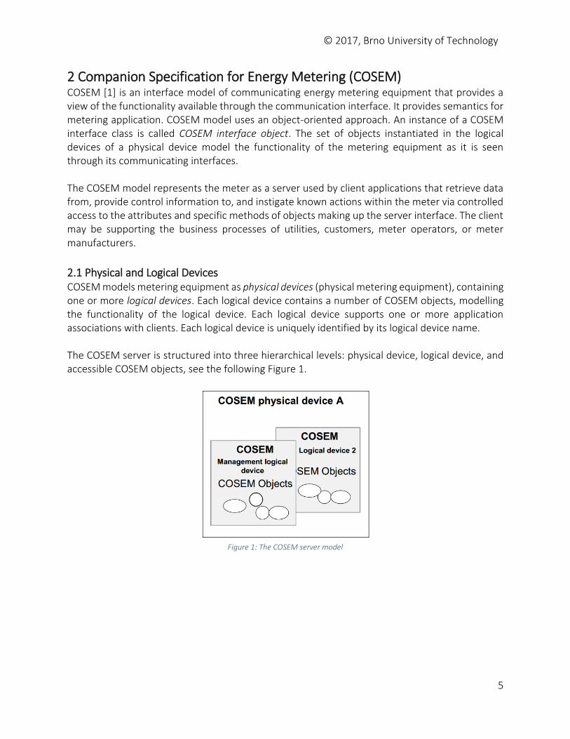
2.1 Physical and Logical Devices COSEM models metering equipment as physical devices (physical metering equipment), containing one or more logical devices. Each logical device contains a number of COSEM objects, modelling the functionality of the logical device. Each logical device supports one or more application associations with clients. Each logical device is uniquely identified by its logical device name. The COSEM server is structured into three hierarchical levels: physical device, logical device, and accessible COSEM objects, see the following Figure 1.
Figure 1: The COSEM server model
© 2017, Brno University of Technology
6
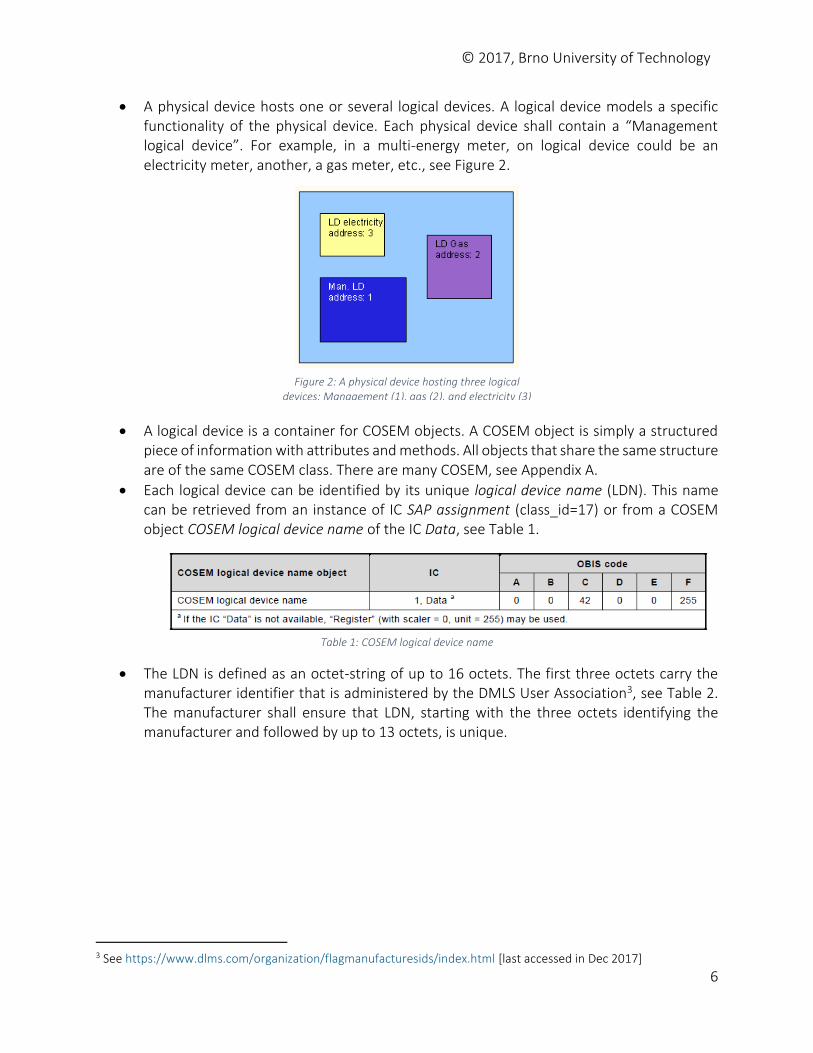
A physical device hosts one or several logical devices. A logical device models a specific functionality of the physical device. Each physical device shall contain a “Management logical device”. For example, in a multi-energy meter, on logical device could be an electricity meter, another, a gas meter, etc., see Figure 2.
A logical device is a container for COSEM objects. A COSEM object is simply a structured piece of information with attributes and methods. All objects that share the same structure are of the same COSEM class. There are many COSEM, see Appendix A.
Each logical device can be identified by its unique logical device name (LDN). This name can be retrieved from an instance of IC SAP assignment (class_id=17) or from a COSEM object COSEM logical device name of the IC Data, see Table 1.
Table 1: COSEM logical device name
The LDN is defined as an octet-string of up to 16 octets. The first three octets carry the manufacturer identifier that is administered by the DMLS User Association3, see Table 2. The manufacturer shall ensure that LDN, starting with the three octets identifying the manufacturer and followed by up to 13 octets, is unique.
3 See https://www.dlms.com/organization/flagmanufacturesids/index.html [last accessed in Dec 2017]
Figure 2: A physical device hosting three logical devices: Management (1), gas (2), and electricity (3)
© 2017, Brno University of Technology
7
Table 2: Example of Manufacturers Flags registered by DLMS User Association
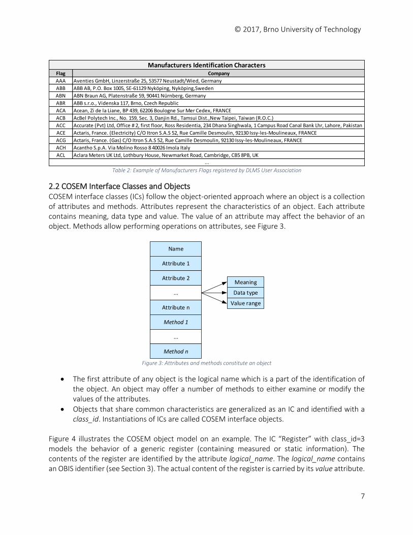
2.2 COSEM Interface Classes and Objects COSEM interface classes (ICs) follow the object-oriented approach where an object is a collection of attributes and methods. Attributes represent the characteristics of an object. Each attribute contains meaning, data type and value. The value of an attribute may affect the behavior of an object. Methods allow performing operations on attributes, see Figure 3.
Name
Attribute 1
Attribute 2
...
Attribute n
Method 1
...
Method n
Meaning
Data type
Value range
Figure 3: Attributes and methods constitute an object
The first attribute of any object is the logical name which is a part of the identification of the object. An object may offer a number of methods to either examine or modify the values of the attributes.
Objects that share common characteristics are generalized as an IC and identified with a class_id. Instantiations of ICs are called COSEM interface objects.
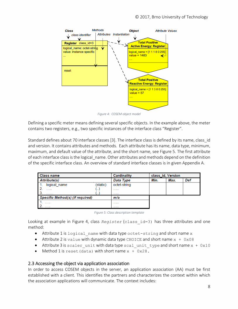
Figure 4 illustrates the COSEM object model on an example. The IC “Register” with class_id=3 models the behavior of a generic register (containing measured or static information). The contents of the register are identified by the attribute logical_name. The logical_name contains an OBIS identifier (see Section 3). The actual content of the register is carried by its value attribute.
Flag Company
AAA Aventies GmbH, Linzerstraße 25, 53577 Neustadt/Wied, Germany
ABB ABB AB, P.O. Box 1005, SE-61129 Nyköping, Nyköping,Sweden
ABN ABN Braun AG, Platenstraße 59, 90441 Nürnberg, Germany
ABR ABB s.r.o., Videnska 117, Brno, Czech Republic
ACA Acean, Zi de la Liane, BP 439, 62206 Boulogne Sur Mer Cedex, FRANCE
ACB AcBel Polytech Inc., No. 159, Sec. 3, Danjin Rd., Tamsui Dist.,New Taipei, Taiwan (R.O.C.)
ACC Accurate (Pvt) Ltd, Office # 2, first floor, Ross Residentia, 234 Dhana Singhwala, 1 Campus Road Canal Bank Lhr, Lahore, Pakistan
ACE Actaris, France. (Electricity) C/O Itron S.A.S 52, Rue Camille Desmoulin, 92130 Issy-les-Moulineaux, FRANCE
ACG Actaris, France. (Gas) C/O Itron S.A.S 52, Rue Camille Desmoulin, 92130 Issy-les-Moulineaux, FRANCE
ACH Acantho S.p.A. Via Molino Rosso 8 40026 Imola Italy
ACL Aclara Meters UK Ltd, Lothbury House, Newmarket Road, Cambridge, CB5 8PB, UK
Manufacturers Identification Characters
...
© 2017, Brno University of Technology
8
Figure 4: COSEM object model
Defining a specific meter means defining several specific objects. In the example above, the meter contains two registers, e.g., two specific instances of the interface class “Register”. Standard defines about 70 interface classes [3]. The interface class is defined by its name, class_id and version. It contains attributes and methods. Each attribute has its name, data type, minimum, maximum, and default value of the attribute, and the short name, see Figure 5. The first attribute of each interface class is the logical_name. Other attributes and methods depend on the definition of the specific interface class. An overview of standard interface classes is in given Appendix A.
Figure 5: Class description template
Looking at example in Figure 4, class Register (class_id=3) has three attributes and one method:
Attribute 1 is logical_name with data type octet-string and short name x
Attribute 2 is value with dynamic data type CHOICE and short name x + 0x08
Attribute 3 is scaler_unit with data type scal_unit_type and short name x + 0x10 Method 1 is reset(data) with short name x + 0x28.
2.3 Accessing the object via application association In order to access COSEM objects in the server, an application association (AA) must be first established with a client. This identifies the partners and characterizes the context within which the association applications will communicate. The context includes:
© 2017, Brno University of Technology
9
the application context
the authentication context
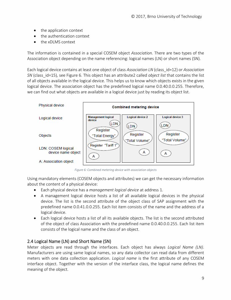
the xDLMS context The information is contained in a special COSEM object Association. There are two types of the Association object depending on the name referencing: logical names (LN) or short names (SN). Each logical device contains at least one object of class Association LN (class_id=12) or Association SN (class_id=15), see Figure 6. This object has an attribute2 called object list that contains the list of all objects available in the logical device. This helps us to know which objects exists in the given logical device. The association object has the predefined logical name 0.0.40.0.0.255. Therefore, we can find out what objects are available in a logical device just by reading its object list.
Figure 6: Combined metering device with association objects
Using mandatory elements (COSEM objects and attributes) we can get the necessary information about the content of a physical device:
Each physical device has a management logical device at address 1.
A management logical device hosts a list of all available logical devices in the physical device. The list is the second attribute of the object class of SAP assignment with the predefined name 0.0.41.0.0.255. Each list item consists of the name and the address of a logical device.
Each logical device hosts a list of all its available objects. The list is the second attributed of the object of class Association with the predefined name 0.0.40.0.0.255. Each list item consists of the logical name and the class of an object.
2.4 Logical Name (LN) and Short Name (SN) Meter objects are read through the interfaces. Each object has always Logical Name (LN). Manufacturers are using same logical names, so any data collector can read data from different meters with one data collection application. Logical name is the first attribute of any COSEM interface object. Together with the version of the interface class, the logical name defines the meaning of the object.
© 2017, Brno University of Technology
10
The logical name consists of a string of six values defined according to a system called OBIS (Object Identification System), e.g., 1.1.1.8.0.255, see Section 3. OBIS allows to uniquely identify each of the many data items used in the energy metering equipment. Attributes and methods of COSEM objects can be accessed using referencing. There are two different ways how to reference COSEM objects:
Logical Name (LN) referencing is a way how to access attributes and methods of COSEM interface objects using the identifier of the COSEM interface class and the COSEM object instance to which these attributes and methods belong.
o The reference for an attribute is: class_id, value of the logical_name
attribute, attribute_index o The reference for a method is: class_id, value of the logical_name attribute,
method_index. Attribute and method indexes are specified in the definition of each IC. They are positive numbers starting with one. Proprietary attributes may be added (these use negative numbers).
Short name (SN) referencing is a way how to access attributes and methods of COSEM interface objects after the first mapping them to short names. This kind of referencing is intended for use in simple devices. In this case, each attribute and method of a COSEM object is identified with a 13-bit integer. The syntax is the same as the syntax of a DLMS named variable. When SN referencing is used, each attribute and method of object instances has to be mapped to short names. The base_name x of each object instance is the DLMS name variable the logical name attribute is mapped to. It is selected in the implementation phase. The IC definition specifies the offset for the other attributes and for the methods. Short Name (SN) is an identifier of a COSEM interface object attribute or method, using the syntax of a DLMS named variable. Short names are assigned during the process of mapping during the design phase of a DLMS/COSEM metering equipment. For example, the class Register (id=3) has three attributes (logical_name, value, scaler_unit) and one method (reset). The short names for these elements are: base_name is x refers to the logical_name. The short name of the attribute value is x + 0x08 (offset 0x08), the SN of scaler_unit is x + 0x10, the SN of reset method is x + 0x28.
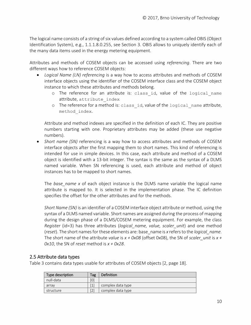
2.5 Attribute data types Table 3 contains data types usable for attributes of COSEM objects [2, page 18].
Type description Tag Definition
null-data [0]
array [1] complex data type
structure [2] complex data type

© 2017, Brno University of Technology
11
boolean [3] TRUE or FALSE
bit-string [4] An ordered sequence of boolean values
double-long [5] Integer32
double-long-unsigned [6] Unsigned32
octet-string [9] An ordered sequence of octets (8 bit bytes)
visible-string [10] An ordered sequence of ASCII characters
UTF8-string [12] An ordered sequence of characters encoded as UTF-8
bcd [13] binary coded decimal
integer [15] Integer8
long [16] Integer16
unsigned [17] Unsigned8
long-unsigned [18] Unsigned16
compact array [19] complex data type
long64 [20] Integer64
long64-unsigned [21] Unsigned64
enum [22] 0..255
float32 [23] OCTET STRING (SIZE(4))
float64 [24] OCTET STRING (SIZE(8))
date_time [25] OCTET STRING (SIZE(12))
date [26] OCTET STRING (SIZE(5))
time [27] OCTET STRING (SIZE(4)) Table 3: Data types of COSEM objects
Floating-point numbers shall be represented as a fixed length octet-strings, containing 4 bytes (float32) of the single format or 8 bytes (float64) of the double format floating-point number in the following format: the sign bit (1 bit), the exponent (8 or 11 bits), the fraction (23 or 52 bits) according to the standard IEC 60559.
© 2017, Brno University of Technology
12
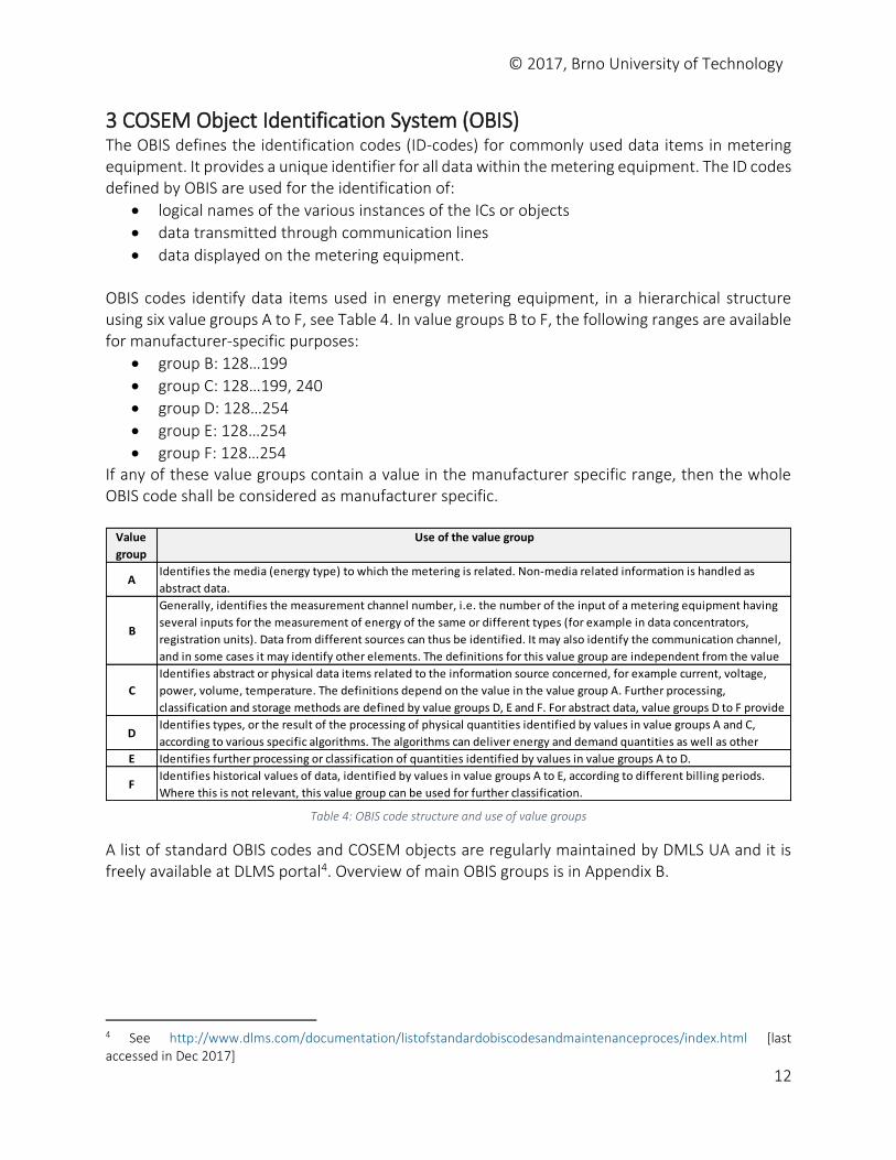
3 COSEM Object Identification System (OBIS) The OBIS defines the identification codes (ID-codes) for commonly used data items in metering equipment. It provides a unique identifier for all data within the metering equipment. The ID codes defined by OBIS are used for the identification of:
logical names of the various instances of the ICs or objects
data transmitted through communication lines
data displayed on the metering equipment. OBIS codes identify data items used in energy metering equipment, in a hierarchical structure using six value groups A to F, see Table 4. In value groups B to F, the following ranges are available for manufacturer-specific purposes:
group B: 128…199
group C: 128…199, 240
group D: 128…254
group E: 128…254
group F: 128…254 If any of these value groups contain a value in the manufacturer specific range, then the whole OBIS code shall be considered as manufacturer specific.
A list of standard OBIS codes and COSEM objects are regularly maintained by DMLS UA and it is freely available at DLMS portal4. Overview of main OBIS groups is in Appendix B.
4 See http://www.dlms.com/documentation/listofstandardobiscodesandmaintenanceproces/index.html [last accessed in Dec 2017]
Value
group
Use of the value group
AIdentifies the media (energy type) to which the metering is related. Non-media related information is handled as
abstract data.
B
Generally, identifies the measurement channel number, i.e. the number of the input of a metering equipment having
several inputs for the measurement of energy of the same or different types (for example in data concentrators,
registration units). Data from different sources can thus be identified. It may also identify the communication channel,
and in some cases it may identify other elements. The definitions for this value group are independent from the value
C
Identifies abstract or physical data items related to the information source concerned, for example current, voltage,
power, volume, temperature. The definitions depend on the value in the value group A. Further processing,
classification and storage methods are defined by value groups D, E and F. For abstract data, value groups D to F provide
DIdentifies types, or the result of the processing of physical quantities identified by values in value groups A and C,
according to various specific algorithms. The algorithms can deliver energy and demand quantities as well as other
E Identifies further processing or classification of quantities identified by values in value groups A to D.
FIdentifies historical values of data, identified by values in value groups A to E, according to different billing periods.
Where this is not relevant, this value group can be used for further classification.
Table 4: OBIS code structure and use of value groups
© 2017, Brno University of Technology
13
4 DLMS/COSEM Communications Framework DLMS/COSEM (IEC 62056-53, IEC 62056-62) is a standard specification using COSEM for interface modeling equipment and DLMS for data exchange of such metering equipment. It comprises the object model, the application layer protocol and the communication profiles to transport the messages. In ISO OSI model DLMS communicates over L4-L5 (transport and session layer), COSEM forms presentation layer (L6), see Table 5.
Layer Function DLMS/COSEM Application Network process to application Application
Presentation Data representation, encryption and decryption, convert machine dependent data to machine independent data
COSEM
Session Interhost communication, managing sessions between applications
DLMS
Transport End-to-end connections, reliability and flow control DLMS
Network Path determination and logical addressing DLMS
Data link Physical addressing HDLC, IEC 62056-47
Physical Media, signal and binary transmission Serial media, cable, radio Table 5: DLMS and ISO OSI model
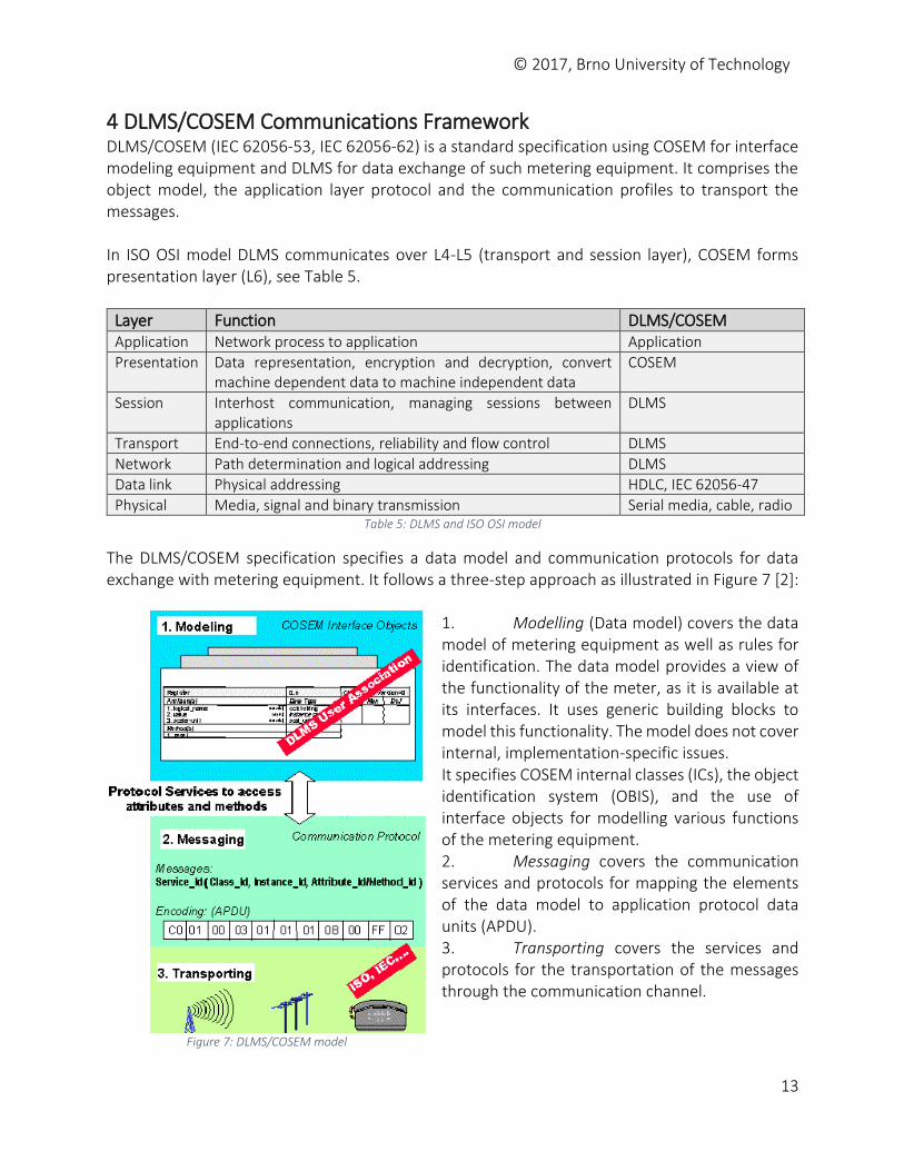
The DLMS/COSEM specification specifies a data model and communication protocols for data exchange with metering equipment. It follows a three-step approach as illustrated in Figure 7 [2]:
1. Modelling (Data model) covers the data model of metering equipment as well as rules for identification. The data model provides a view of the functionality of the meter, as it is available at its interfaces. It uses generic building blocks to model this functionality. The model does not cover internal, implementation-specific issues. It specifies COSEM internal classes (ICs), the object identification system (OBIS), and the use of interface objects for modelling various functions of the metering equipment. 2. Messaging covers the communication services and protocols for mapping the elements of the data model to application protocol data units (APDU). 3. Transporting covers the services and protocols for the transportation of the messages through the communication channel.
Figure 7: DLMS/COSEM approach
Figure 7: DLMS/COSEM model
© 2017, Brno University of Technology
14
In DLMS/COSEM, clients always use data communication services with logical names referencing. The server may use either services with logical name referencing or with short name referencing. For LN referencing, DLSM/COSEM defines following client/server services:
GET service – retrieves attributes of COSEM interface objects
SET service – modifies attributes of COSEM interface objects
ACTION service – invokes methods of COSEM interface objects
EventNotification service – using this service, the server is able to send an unsolicited notification of the occurrence of an event to the client.
For SN referencing, DLMS/COSEM defines following services:
Read
Write
Unconfirmed Write operations
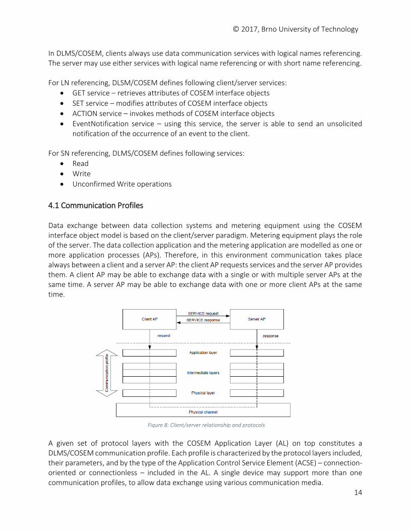
4.1 Communication Profiles Data exchange between data collection systems and metering equipment using the COSEM interface object model is based on the client/server paradigm. Metering equipment plays the role of the server. The data collection application and the metering application are modelled as one or more application processes (APs). Therefore, in this environment communication takes place always between a client and a server AP: the client AP requests services and the server AP provides them. A client AP may be able to exchange data with a single or with multiple server APs at the same time. A server AP may be able to exchange data with one or more client APs at the same time.
A given set of protocol layers with the COSEM Application Layer (AL) on top constitutes a DLMS/COSEM communication profile. Each profile is characterized by the protocol layers included, their parameters, and by the type of the Application Control Service Element (ACSE) – connection-oriented or connectionless – included in the AL. A single device may support more than one communication profiles, to allow data exchange using various communication media.
Figure 8: Client/server relationship and protocols
© 2017, Brno University of Technology
15
DLMS specifies two communication profiles [5]:
HDLC based profile o The 3-layer, connection-oriented HDLC based profile includes three layers: the
physical layer (serial connection), HDLC layer and the application layer. It supports data exchange via a local optical or electrical port according to IEC 62056-21, leased lines and the PSTN or the GSM telephone network.
o The client HDLC address (also called MAC address) is a byte value, e.g., 16 for public clients. The server MAC address is divided into two parts: the upper part is the logical device address, and the lower part is the physical device address. In some cases (e.g., point-to-point topology), the lower part can be omitted. The length of the server address is 1 byte (just an upper address), 2 bytes (1 byte for the upper address and 1 byte for the lower address), or 4 bytes (2 bytes for the upper address and 2 bytes for the lower address).
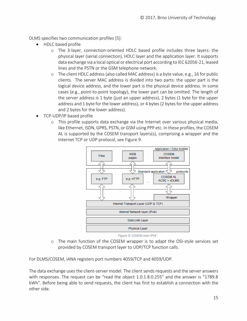
TCP-UDP/IP based profile o This profile supports data exchange via the Internet over various physical media,
like Ethernet, ISDN, GPRS, PSTN, or GSM using PPP etc. In these profiles, the COSEM AL is supported by the COSEM transport layers(s), comprising a wrapper and the Internet TCP or UDP protocol, see Figure 9.
o The main function of the COSEM wrapper is to adapt the OSI-style services set provided by COSEM transport layer to UDP/TCP function calls.
For DLMS/COSEM, IANA registers port numbers 4059/TCP and 4059/UDP. The data exchange uses the client-server model. The client sends requests and the server answers with responses. The request can be “read the object 1.0.1.8.0.255” and the answer is “1789.8 kWh”. Before being able to send requests, the client has first to establish a connection with the other side.
Figure 9: COSEM over IPv4
© 2017, Brno University of Technology
16
4.2 COSEM Application Layer The COSEM application layer contains three mandatory components both on the client and the server side:
the Application Control Service Element (ACSE) o The task of ASCE is to establish, maintain, and release application associations. o Encoding the ACSE AARQ and AARE APDUs are in BER.
the extended DLMS Application Service Element, xDLMS_ASE o The task of the xDLMS_ASE is to provide data transfer services between COSEM
application processes. It is based on DLMS standard IEC 61334-4-41. It has been extended for DLMS/COSEM.
o xDLMS data transfer services are related to attributes and methods of COSEM interface objects [2]. For accessing these attributes and methods, client/server type services are used: the client requests services and the server provides them. There is also an unsolicited non-client/server type service. This service is requested by the server, upon an occurrence of an event, to inform the client of the value of one or more attributes, as though they had been requested by the client. It is an unconfirmed service.
o Encoding the xDLMS APDUs carrying the data transfer services in A-XDR [4].
the Control Function (CF) o The CF element specifies how the ASO service invoke the appropriate service
primitives of the ACSE, the xDLMS_ASE and the services of the supporting layer.
4.3 Data Transfer Services COSEM defines two distinct service sets – one for logical name (LN) referencing and one for short name (SN) referencing:
COSEM client/server type data transfer services for LN referencing are the following: o GET service: it is used to read the value of one or more attributes of COSEM objects. o SET service: it is used to write the value of one or more attributes of COSEM objects. o ACTION service: it is used to invoke one or more methods of COSEM objects.
Invoking methods may imply sending service parameters and returning data. o EventNotification service: this is a non-client/server type service.
COSEM client/server type data transfer services for SN referencing are the following: o Read service: it is used to read the value of one or more attributes or to invoke one
or more methods of COSEM objects. It is a confirmed service. o Write service: It is used to write the value of one or more attributes or to invoke
one or more methods of COSEM objects. It is a confirmed service. o UnconfirmedWrite service: it is used to write the value of one or more attributes or
invoke one or more methods of COSEM objects. It is an unconfirmed service. o InformationReport service: this is a non-client/server type service.
The format of DLMS/COSEM APDUs is described in [9] and in Appendix D.
© 2017, Brno University of Technology
17
4.4 Application Layer PDUs COSEM application layer includes the ASCE and xDLMS ASE.
4.4.1 The Association Control Service Element (ACSE) services The ACSE provides services to establish and release application associations (AAs).
AARQ (A-Associate Request)
AARE (A-Associate Response)
RLRQ (A-Release Request)
RLRE (A-Release Response) The ACSE APDUs are encoded in BER. The user-information parameter of these APDUs, shall carry the xDMLS InitiateRequest / InitiateResponse / confirmedServiceError APDU as appropriate, encoded in A-XDR, and then encoding the resulting OCTET STRING in BER.
4.4.2 The xDLMS Assocation Service Element (ASE) To access attributes and methods of COSEM objects, the services of the xDLMS ASE are used. It provides services to transport date between COSEM APs. xDLMS (extended DLMS) includes some extension to the DLMS standard IEC 61334-4-41 [7]. These extensions define added functionality. They are made in such a way, that there is no conflict with the existing DLMS standard. The extensions comprise the following functions [5]:
additional services- GET, SET, ACTION, and EventNotification;
additional data types;
new DLMS version number – the number of the first version of the xDLMS ASE is 6;
new conformance block – enables optimized DLMS/COSEM server implementations with extended functionality. This block has application data type 31 (Conformance, BIT STRING SIZE (24)), instead of application data type 30 (Conformance, BIT STRING SIZE (16)).
clarification of the meaning of the PDU size – the Proposed Max PDU Size means now the Client Max Receive PDU Size, the Negotiated Max PDU Size means now the Server Max Receive PDU Size.
IEC 61334-6 defines DLMS APDU [7] as follows, see also Appendix C. DLMSpdu ::= CHOICE { confirmedServiceRequest [0] RequestToConfirmedService, initiateRequest [1] RequestToInitiate, getStatusRequest [2] RequestToGetStatus, getNameListRequest [3] RequestToGetNameList, getVariableAttributeRequest [4] RequestToGetVariableAttribute,
readRequest [5] RequestToRead, writeRequest [6] RequestToWrite,
© 2017, Brno University of Technology
18
confirmedServiceResponse [7] ResponseToConfirmedService, initiateResponse [8] ResponseToInitiate, getStatusResponse [9] ResponseToGetStatus, getNameListResponse [10] ResponseToGetNameList, getVariableAttributeResponse [11] ResponseToGetVariableAttribute, readResponse [12] ResponseToRead, writeResponse [13] ResponseToWrite, confirmedServiceError [14] ErrorConfirmedService, unconfirmedServiceRequest [15] RequestToUnconfirmedService, abortRequest [16] RequestToAbort, unconfirmedWriteRequest [17] RequestToUnconfirmedWrite, unsolicitedServiceRequest [18] RequestToUnsolicitedService, informationReportRequest [19] RequestToInformationReport, …
(encoded PDUs) … ded-informationReportRequest [88] OCTET STRING }
4.4.3 The Adaptive External Data Representation (A-XDR) DLMS PDUs are encoded using A-XDR encoding [4].
Example 1: Encoding xDLMS-Initiate.request PDU in xDLMS (Extended DLMS) This type of DLMS APDU is usually carried in AARQ ACSE. The format of the APDU is as follows:
xDLMS-Initiate.request :: = SEQUENCE{ dedicated-key OCTET STRING OPTIONAL, response-allowed BOOLEAN DEFAULT TRUE, proposed-quality-of-service [0] IMPLICIT Integer8 OPTIONAL, proposed-dlms-version-number Unsigned8, proposed-conformance Conformance, client-max-received-pdu-size Unsigned16 (different interpretation for xDLMS) } Knowing APDU format we are able to encode and decode APDUs of this type. Suppose the client with the following values: no ciphering used, response-allowed=TRUE, no proposed-quality-of-service, dlms version set to 6, the proposed-conformance is 00 7E 1F for LN and 1C 03 20 for SN and the client PDU is 1200 (0x04B0). The A-XDR encoding of of such APDU is 01 00 00 00 06 5F 1F 04 00 00 7E 1F 04 B0 for LN
01 – explicit tag of the APDU SEQUENCE InitiateRequest
00 – the dedicated-key (not present => FALSE (00); present => TRUE (01) followed by the OCTET STRING)
00 – the response-allowed (00=FALSE, FF=TRUE)
00 – the proposed-quality-of-service (not present => FALSE (00))
© 2017, Brno University of Technology
19
06 – the proposed-dlms-version-number (unsigned8, value 6). Version 6 means xDLMS with longer Conformance block
5F 1F 04 00 00 7E 1F – the conformance block o As specified in IEC 61334-6, Annex C, the proposed-conformance element of
InitiateRequest PDU is encoded by BER, e.g, represented by TLV format (type-length-value) [8].
o Type 5E 1F is 0101 1111 0001 1111 binary. The first byte (5F) is called an identifier octet with the following meaning: 01 (application type), 0 (primitive type) and 11111 (31) means application tag no. 31. This is defined by xDLMS as Conformance data type [5] represented by the standard data type BIT STRING of size 24, e.g., three bytes. This differs to DLMS where Conformance data has application tag 30 and BIT STRING SIZE (16) [7]. The second byte (1F) is not used5.
o 04 gives the length of the value, e.g., four bytes. o The first byte (00) of BIT STRING represents the number of bits left unused6. Since
it is zero, it means there are not unused bits in the octets and all the bits are important.
o The value of the bit string is 00 7E 1F (in hex) for LN referencing.
04 B0 – the proposed-max-pdu-size (Unsigned16, value 0x4B0) A-XDR encoding of the APDU for SN referencing is 01 00 00 00 06 5F 1F 04 00 1C 03 02 04 B0.
Example 2: Encoding InitiateRequest PDU Suppose DLMS InitiateRequest PDU (not xDLMS) with the following values: no dedicated key, response-allowed FALSE, proposed QoS set to 4, DLMS version 1, maximum PDU size set to 134 (0x86) and conformance value set to 0x1C00.
RequestToInitiate :: = SEQUENCE { dedicated-key OCTET STRING OPTIONAL, response-allowed BOOLEAN DEFAULT TRUE, proposed-quality-of-service [0] IMPLICIT Integer8 OPTIONAL, proposed-dlms-version-number Unsigned8, proposed-conformance Conformance, proposed-max-pdu-size Unsigned16 } This PDU will be encoded by A-XDR as 01 00 00 01 04 01 5E 03 00 10 C3 00 86 as follows:
01 – explicit tag of the APDU SEQUENCE InitiateRequest
5 For compliance with existing implementations, encoding of the Application 31 tag on one byte (5F) instead of two bytes (5F 1F) is accepted when the 3-layer, connection-oriented, HDLS based profile is used. 6 For example, BIT STRING 1011 0111 0101 1 (13 bits) will be aligned to two octets (16 bits), e.g., 1011 0111 0101
1000, thus three zero bits are left added to align the bit string to octets. BER encoding will be 0000 0011 1011 0111 0101 1000, where the first octet represents the number of left added zero bits (3) and two following octets represent the bit string without three last zero bits.
© 2017, Brno University of Technology
20
00 – the dedicated-key (FALSE, not present)
00 – the response-allowed FALSE
00 – the proposed-quality-of-service (TRUE, is present)
04 – the value of QoS (Integer8)
01 – the proposed-dlms-version (value 1)
5E 03 00 10 C3 – the conformance block o 5E (0101 1110) is the octet identifier. 01 means application type, primitive (0) with
application data type 11110 (30) which means Conformance data type BIT STRING (SIZE(16))
o the length of 03 bytes o 00 10 C3 is BIT STRING with the number of unused bits 00. The value of the bit
string is 10 C3 (two bytes).
00 86 – max PDU size (134 bytes in decimal)
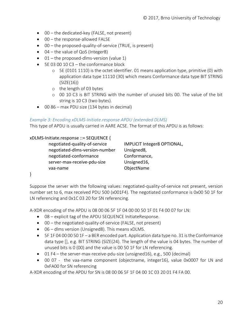
Example 3: Encoding xDLMS-Initiate.response APDU (extended DLMS) This type of APDU is usually carried in AARE ACSE. The format of this APDU is as follows: xDLMS-Initiate.response ::= SEQUENCE { negotiated-quality-of-service IMPLICIT Integer8 OPTIONAL, negotiated-dlms-version-number Unsigned8, negotiated-conformance Conformance, server-max-receive-pdu-size Unsigned16, vaa-name ObjectName } Suppose the server with the following values: negotiated-quality-of-service not present, version number set to 6, max received PDU 500 (x001F4). The negotiated conformance is 0x00 50 1F for LN referencing and 0x1C 03 20 for SN referencing. A-XDR encoding of the APDU is 08 00 06 5F 1F 04 00 00 50 1F 01 F4 00 07 for LN:
08 – explicit tag of the APDU SEQUENCE InitiateResponse.
00 – the negotiated-quality-of-service (FALSE, not present)
06 – dlms version (Unsigned8). This means xDLMS.
5F 1F 04 00 00 50 1F – a BER encoded part. Application data type no. 31 is the Conformance data type [], e.g. BIT STRING (SIZE(24). The length of the value is 04 bytes. The number of unused bits is 0 (00) and the value is 00 50 1F for LN referencing.
01 F4 – the server-max-receive-pdu-size (unsigned16), e.g., 500 (decimal)
00 07 - the vaa-name component (objectname, integer16), value 0x0007 for LN and 0xFA00 for SN referencing
A-XDR encoding of the APDU for SN is 08 00 06 5F 1F 04 00 1C 03 20 01 F4 FA 00.

© 2017, Brno University of Technology
21
Example 4: Encoding InitiateResponse APDU Another example of DLMS APDU InitiateResponse has the values as in Example 2 and the vaa-name set to 0x0037. ResponseToInitiate ::= SEQUENCE { negotiated-quality-of-service IMPLICIT Integer8 OPTIONAL, negotiated-dlms-version-number Unsigned8, negotiated-conformance Conformance, server-max-receive-pdu-size Unsigned16, vaa-name ObjectName } A-XDR encoding of the APDU is 08 01 04 01 5E 03 00 1C 00 00 86 00 37.
08 – explicit tag of the APDU SEQUENCE InitiateResponse.
01 – the negotiated-quality-of-service (TRUE, is present)
04 – the value of QoS (Unsigned8)
01 – dlms version (Unsigned8)
5E 03 00 1C 00 – a BER encoded part. o 5E is the application tag (30) referring Conformance data type which is BIT STRING
SIZE (24). o 03 is the length of the value o 00 is the number of unused bits (no unused bits). o 1C 00 is the conformance value.
00 86 – max PDU size (Unsigned16), e.g., 134 in decimal.
00 37 – the vaa-name (objectname). Object name is Integer16.
4.5 The Addressing In the DLMS/COSEM communication, each side of the connection has an address. By definition, the client address is a byte value. The value of the client address determines also the real nature of the client. The standard states that a client with address 16 is a public client. There can be other kind of clients: a data collection system, a manufacturer, a consumer, etc. The address is composed of the address of the physical device and the address of the logical device.
4.6 The Authentication and the Access Rights Authentication is a process of establishing the true identity of the communicating partners before requesting and providing data communication services. In is one element of the security mechanism provided by DLMS/COSEM. There are three levels of authentication security defined:
1. Lowest Level Security – neither the client nor the server is identified 2. Low Level Security (LLS) – establishes the true identity of the client by verifying a password.
LLS is used when the communication channel provides adequate security to avoid eavesdropping and message replay.
© 2017, Brno University of Technology
22
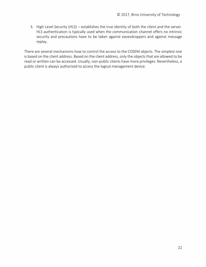
3. High Level Security (HLS) – establishes the true identity of both the client and the server. HLS authentication is typically used when the communication channel offers no intrinsic security and precautions have to be taken against eavesdroppers and against message replay.
There are several mechanisms how to control the access to the COSEM objects. The simplest one is based on the client address. Based on the client address, only the objects that are allowed to be read or written can be accessed. Usually, non-public clients have more privileges. Nevertheless, a public client is always authorized to access the logical management device.
© 2017, Brno University of Technology
23
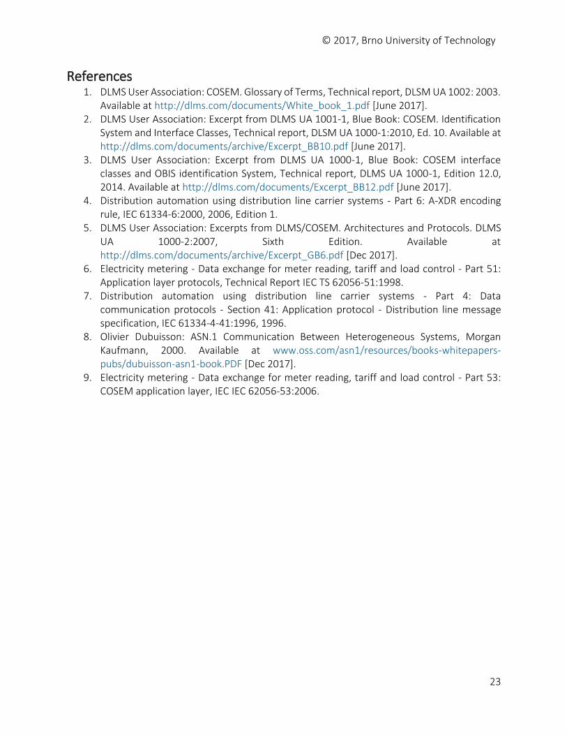
References 1. DLMS User Association: COSEM. Glossary of Terms, Technical report, DLSM UA 1002: 2003.
Available at http://dlms.com/documents/White_book_1.pdf [June 2017]. 2. DLMS User Association: Excerpt from DLMS UA 1001-1, Blue Book: COSEM. Identification
System and Interface Classes, Technical report, DLSM UA 1000-1:2010, Ed. 10. Available at http://dlms.com/documents/archive/Excerpt_BB10.pdf [June 2017].
3. DLMS User Association: Excerpt from DLMS UA 1000-1, Blue Book: COSEM interface classes and OBIS identification System, Technical report, DLMS UA 1000-1, Edition 12.0, 2014. Available at http://dlms.com/documents/Excerpt_BB12.pdf [June 2017].
4. Distribution automation using distribution line carrier systems - Part 6: A-XDR encoding rule, IEC 61334-6:2000, 2006, Edition 1.
5. DLMS User Association: Excerpts from DLMS/COSEM. Architectures and Protocols. DLMS UA 1000-2:2007, Sixth Edition. Available at http://dlms.com/documents/archive/Excerpt_GB6.pdf [Dec 2017].
6. Electricity metering - Data exchange for meter reading, tariff and load control - Part 51: Application layer protocols, Technical Report IEC TS 62056-51:1998.
7. Distribution automation using distribution line carrier systems - Part 4: Data communication protocols - Section 41: Application protocol - Distribution line message specification, IEC 61334-4-41:1996, 1996.
8. Olivier Dubuisson: ASN.1 Communication Between Heterogeneous Systems, Morgan Kaufmann, 2000. Available at www.oss.com/asn1/resources/books-whitepapers-pubs/dubuisson-asn1-book.PDF [Dec 2017].
9. Electricity metering - Data exchange for meter reading, tariff and load control - Part 53: COSEM application layer, IEC IEC 62056-53:2006.
© 2017, Brno University of Technology
24
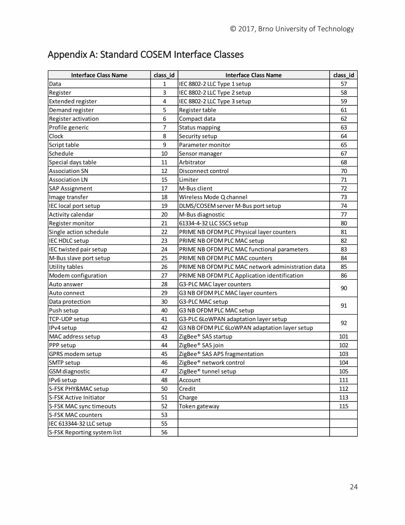
Appendix A: Standard COSEM Interface Classes
Interface Class Name class_id Interface Class Name class_id
Data 1 IEC 8802-2 LLC Type 1 setup 57
Register 3 IEC 8802-2 LLC Type 2 setup 58
Extended register 4 IEC 8802-2 LLC Type 3 setup 59
Demand register 5 Register table 61
Register activation 6 Compact data 62
Profile generic 7 Status mapping 63
Clock 8 Security setup 64
Script table 9 Parameter monitor 65
Schedule 10 Sensor manager 67
Special days table 11 Arbitrator 68
Association SN 12 Disconnect control 70
Association LN 15 Limiter 71
SAP Assignment 17 M-Bus client 72
Image transfer 18 Wireless Mode Q channel 73
IEC local port setup 19 DLMS/COSEM server M-Bus port setup 74
Activity calendar 20 M-Bus diagnostic 77
Register monitor 21 61334-4-32 LLC SSCS setup 80
Single action schedule 22 PRIME NB OFDM PLC Physical layer counters 81
IEC HDLC setup 23 PRIME NB OFDM PLC MAC setup 82
IEC twisted pair setup 24 PRIME NB OFDM PLC MAC functional parameters 83
M-Bus slave port setup 25 PRIME NB OFDM PLC MAC counters 84
Utility tables 26 PRIME NB OFDM PLC MAC network administration data 85
Modem configuration 27 PRIME NB OFDM PLC Application identification 86
Auto answer 28 G3-PLC MAC layer counters
Auto connect 29 G3 NB OFDM PLC MAC layer counters
Data protection 30 G3-PLC MAC setup
Push setup 40 G3 NB OFDM PLC MAC setup
TCP-UDP setup 41 G3-PLC 6LoWPAN adaptation layer setup
IPv4 setup 42 G3 NB OFDM PLC 6LoWPAN adaptation layer setup
MAC address setup 43 ZigBee® SAS startup 101
PPP setup 44 ZigBee® SAS join 102
GPRS modem setup 45 ZigBee® SAS APS fragmentation 103
SMTP setup 46 ZigBee® network control 104
GSM diagnostic 47 ZigBee® tunnel setup 105
IPv6 setup 48 Account 111
S-FSK PHY&MAC setup 50 Credit 112
S-FSK Active Initiator 51 Charge 113
S-FSK MAC sync timeouts 52 Token gateway 115
S-FSK MAC counters 53
IEC 613344-32 LLC setup 55
S-FSK Reporting system list 56
92
91
90
© 2017, Brno University of Technology
25
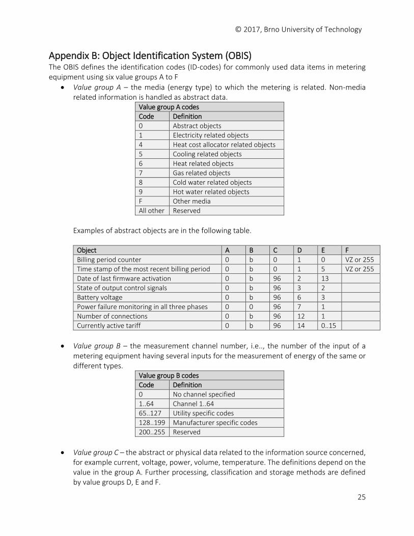
Appendix B: Object Identification System (OBIS) The OBIS defines the identification codes (ID-codes) for commonly used data items in metering equipment using six value groups A to F
Value group A – the media (energy type) to which the metering is related. Non-media related information is handled as abstract data.
Value group A codes
Code Definition
0 Abstract objects
1 Electricity related objects
4 Heat cost allocator related objects
5 Cooling related objects
6 Heat related objects
7 Gas related objects
8 Cold water related objects
9 Hot water related objects
F Other media
All other Reserved
Examples of abstract objects are in the following table.
Object A B C D E F
Billing period counter 0 b 0 1 0 VZ or 255
Time stamp of the most recent billing period 0 b 0 1 5 VZ or 255
Date of last firmware activation 0 b 96 2 13
State of output control signals 0 b 96 3 2
Battery voltage 0 b 96 6 3
Power failure monitoring in all three phases 0 0 96 7 1
Number of connections 0 b 96 12 1
Currently active tariff 0 b 96 14 0..15
Value group B – the measurement channel number, i.e.., the number of the input of a metering equipment having several inputs for the measurement of energy of the same or different types.
Value group B codes
Code Definition
0 No channel specified
1..64 Channel 1..64
65..127 Utility specific codes
128..199 Manufacturer specific codes
200..255 Reserved
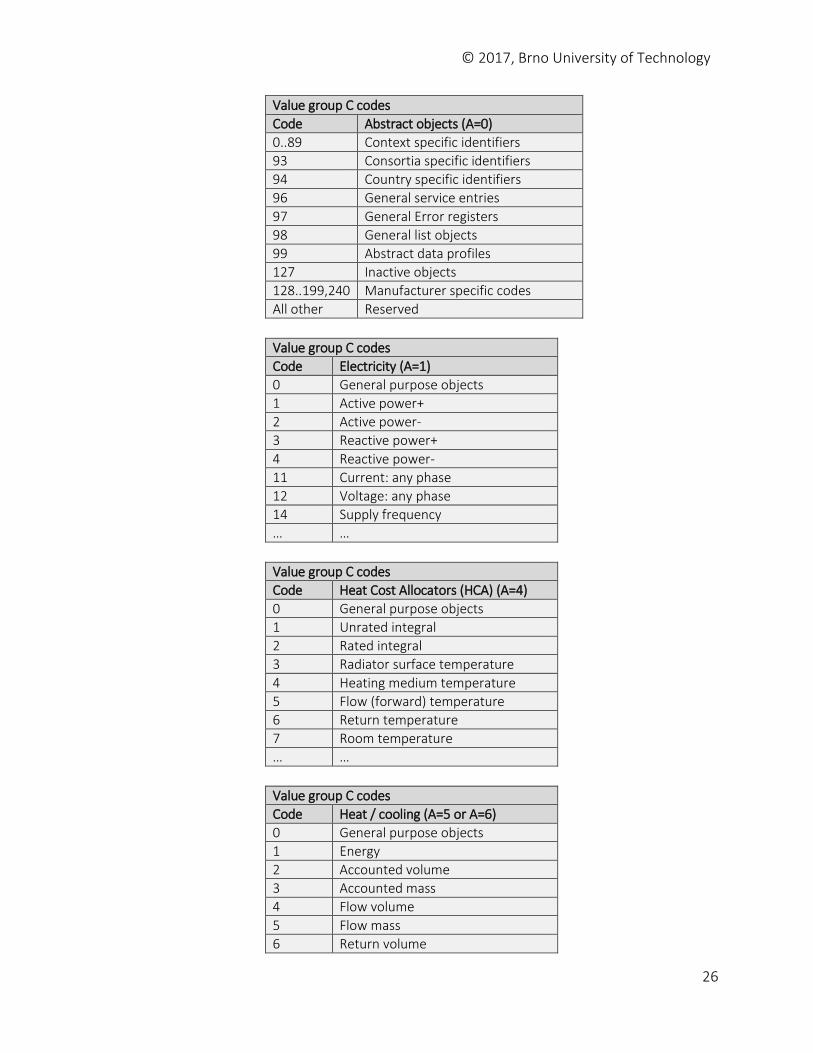
Value group C – the abstract or physical data related to the information source concerned, for example current, voltage, power, volume, temperature. The definitions depend on the value in the group A. Further processing, classification and storage methods are defined by value groups D, E and F.
© 2017, Brno University of Technology
26
Value group C codes
Code Abstract objects (A=0)
0..89 Context specific identifiers
93 Consortia specific identifiers
94 Country specific identifiers
96 General service entries
97 General Error registers
98 General list objects
99 Abstract data profiles
127 Inactive objects
128..199,240 Manufacturer specific codes
All other Reserved
Value group C codes
Code Electricity (A=1)
0 General purpose objects
1 Active power+
2 Active power-
3 Reactive power+
4 Reactive power-
11 Current: any phase
12 Voltage: any phase
14 Supply frequency
… …
Value group C codes
Code Heat Cost Allocators (HCA) (A=4)
0 General purpose objects
1 Unrated integral
2 Rated integral
3 Radiator surface temperature
4 Heating medium temperature
5 Flow (forward) temperature
6 Return temperature
7 Room temperature
… …
Value group C codes
Code Heat / cooling (A=5 or A=6)
0 General purpose objects
1 Energy
2 Accounted volume
3 Accounted mass
4 Flow volume
5 Flow mass
6 Return volume
© 2017, Brno University of Technology
27
7 Return mass
… …
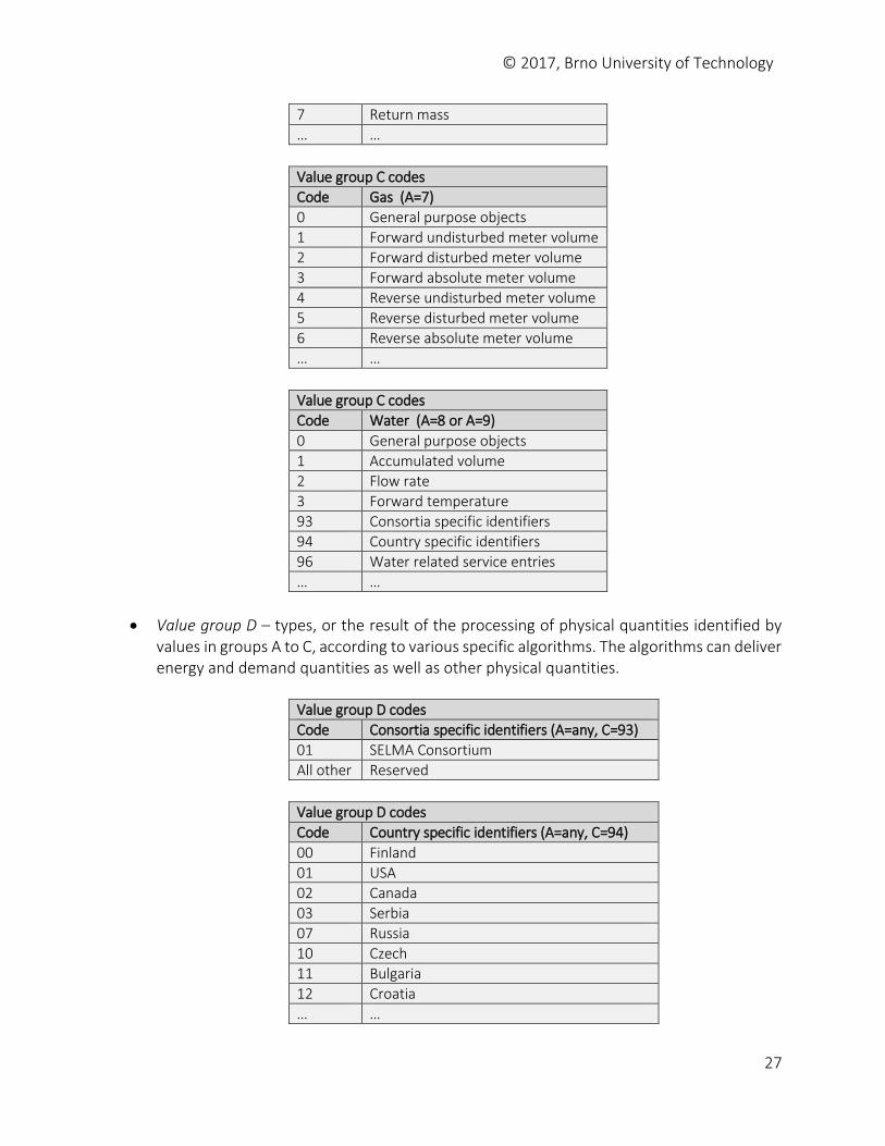
Value group C codes
Code Gas (A=7)
0 General purpose objects
1 Forward undisturbed meter volume
2 Forward disturbed meter volume
3 Forward absolute meter volume
4 Reverse undisturbed meter volume
5 Reverse disturbed meter volume
6 Reverse absolute meter volume
… …
Value group C codes
Code Water (A=8 or A=9)
0 General purpose objects
1 Accumulated volume
2 Flow rate
3 Forward temperature
93 Consortia specific identifiers
94 Country specific identifiers
96 Water related service entries
… …
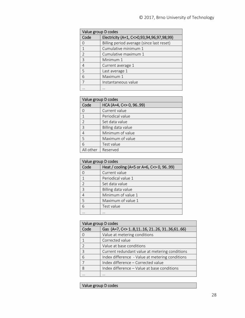
Value group D – types, or the result of the processing of physical quantities identified by values in groups A to C, according to various specific algorithms. The algorithms can deliver energy and demand quantities as well as other physical quantities.
Value group D codes
Code Consortia specific identifiers (A=any, C=93)
01 SELMA Consortium
All other Reserved
Value group D codes
Code Country specific identifiers (A=any, C=94)
00 Finland
01 USA
02 Canada
03 Serbia
07 Russia
10 Czech
11 Bulgaria
12 Croatia
… …
© 2017, Brno University of Technology
28
Value group D codes
Code Electricity (A=1, C<>0,93,94,96,97,98,99)
0 Billing period average (since last reset)
1 Cumulative minimum 1
2 Cumulative maximum 1
3 Minimum 1
4 Current average 1
5 Last average 1
6 Maximum 1
7 Instantaneous value
… …
Value group D codes
Code HCA (A=4, C<> 0, 96..99)
0 Current value
1 Periodical value
2 Set data value
3 Billing data value
4 Minimum of value
5 Maximum of value
6 Test value
All other Reserved
Value group D codes
Code Heat / cooling (A=5 or A=6, C<> 0, 96..99)
0 Current value
1 Periodical value 1
2 Set data value
3 Billing data value
4 Minimum of value 1
5 Maximum of value 1
6 Test value
… …
Value group D codes
Code Gas (A=7, C<> 1..8,11..16, 21..26, 31..36,61..66)
0 Value at metering conditions
1 Corrected value
2 Value at base conditions
3 Current redundant value at metering conditions
6 Index difference - Value at metering conditions
7 Index difference – Corrected value
8 Index difference – Value at base conditions
… …
Value group D codes
© 2017, Brno University of Technology
29
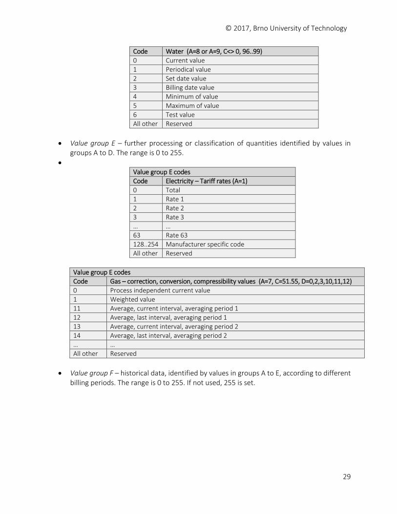
Code Water (A=8 or A=9, C<> 0, 96..99)
0 Current value
1 Periodical value
2 Set date value
3 Billing date value
4 Minimum of value
5 Maximum of value
6 Test value
All other Reserved
Value group E – further processing or classification of quantities identified by values in groups A to D. The range is 0 to 255.
Value group E codes
Code Electricity – Tariff rates (A=1)
0 Total
1 Rate 1
2 Rate 2
3 Rate 3
… …
63 Rate 63
128..254 Manufacturer specific code
All other Reserved
Value group E codes
Code Gas – correction, conversion, compressibility values (A=7, C=51.55, D=0,2,3,10,11,12)
0 Process independent current value
1 Weighted value
11 Average, current interval, averaging period 1
12 Average, last interval, averaging period 1
13 Average, current interval, averaging period 2
14 Average, last interval, averaging period 2
… …
All other Reserved
Value group F – historical data, identified by values in groups A to E, according to different billing periods. The range is 0 to 255. If not used, 255 is set.
© 2017, Brno University of Technology
30
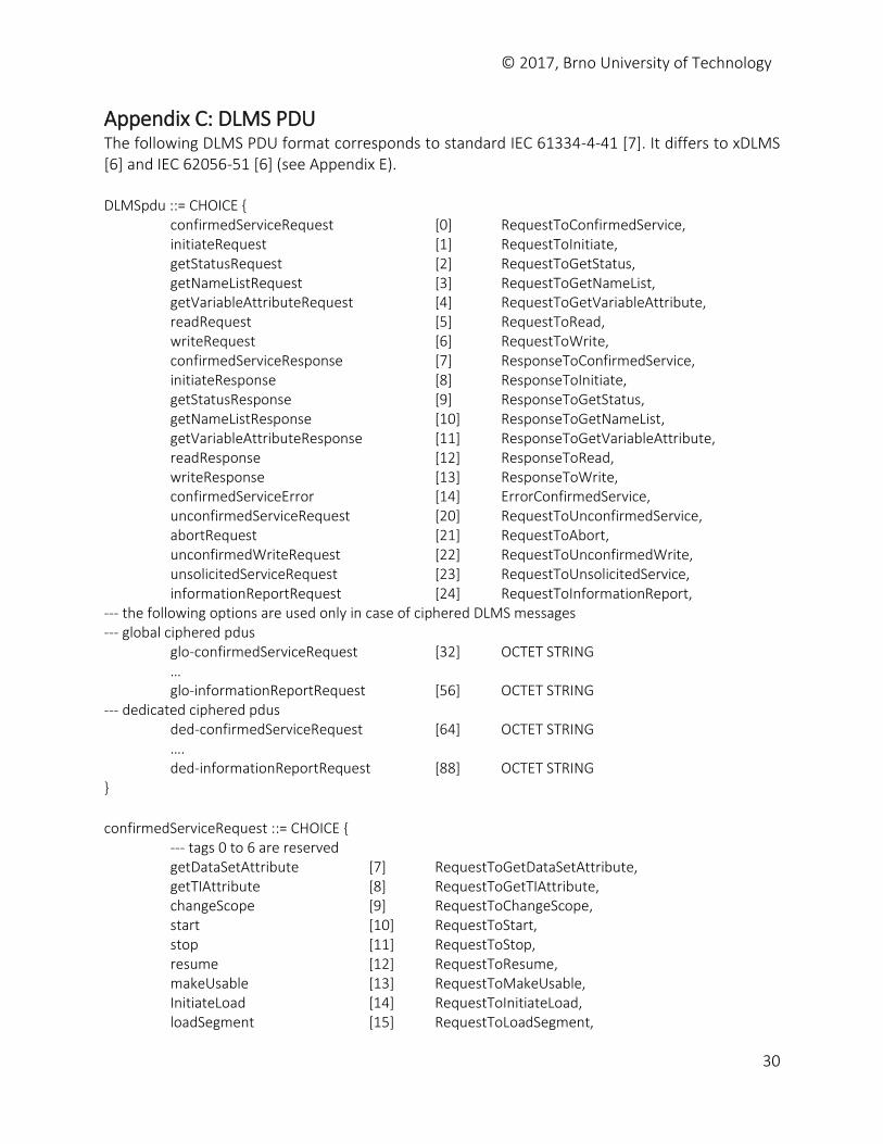
Appendix C: DLMS PDU The following DLMS PDU format corresponds to standard IEC 61334-4-41 [7]. It differs to xDLMS [6] and IEC 62056-51 [6] (see Appendix E). DLMSpdu ::= CHOICE { confirmedServiceRequest [0] RequestToConfirmedService, initiateRequest [1] RequestToInitiate, getStatusRequest [2] RequestToGetStatus, getNameListRequest [3] RequestToGetNameList, getVariableAttributeRequest [4] RequestToGetVariableAttribute,
readRequest [5] RequestToRead, writeRequest [6] RequestToWrite, confirmedServiceResponse [7] ResponseToConfirmedService, initiateResponse [8] ResponseToInitiate, getStatusResponse [9] ResponseToGetStatus, getNameListResponse [10] ResponseToGetNameList, getVariableAttributeResponse [11] ResponseToGetVariableAttribute, readResponse [12] ResponseToRead, writeResponse [13] ResponseToWrite, confirmedServiceError [14] ErrorConfirmedService, unconfirmedServiceRequest [20] RequestToUnconfirmedService, abortRequest [21] RequestToAbort, unconfirmedWriteRequest [22] RequestToUnconfirmedWrite, unsolicitedServiceRequest [23] RequestToUnsolicitedService, informationReportRequest [24] RequestToInformationReport,
--- the following options are used only in case of ciphered DLMS messages --- global ciphered pdus glo-confirmedServiceRequest [32] OCTET STRING … glo-informationReportRequest [56] OCTET STRING --- dedicated ciphered pdus ded-confirmedServiceRequest [64] OCTET STRING …. ded-informationReportRequest [88] OCTET STRING }
confirmedServiceRequest ::= CHOICE { --- tags 0 to 6 are reserved getDataSetAttribute [7] RequestToGetDataSetAttribute, getTIAttribute [8] RequestToGetTIAttribute, changeScope [9] RequestToChangeScope, start [10] RequestToStart, stop [11] RequestToStop, resume [12] RequestToResume, makeUsable [13] RequestToMakeUsable, InitiateLoad [14] RequestToInitiateLoad, loadSegment [15] RequestToLoadSegment,
© 2017, Brno University of Technology
31
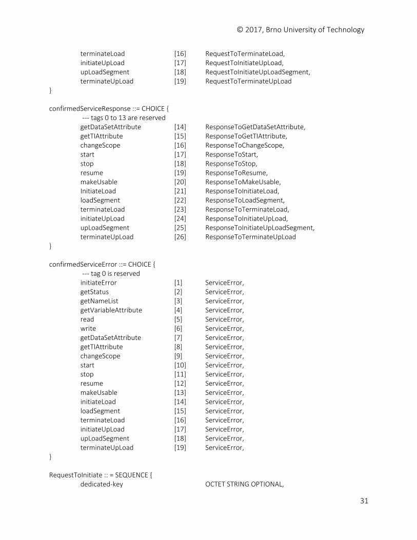
terminateLoad [16] RequestToTerminateLoad, initiateUpLoad [17] RequestToInitiateUpLoad, upLoadSegment [18] RequestToInitiateUpLoadSegment, terminateUpLoad [19] RequestToTerminateUpLoad } confirmedServiceResponse ::= CHOICE {
--- tags 0 to 13 are reserved getDataSetAttribute [14] ResponseToGetDataSetAttribute, getTIAttribute [15] ResponseToGetTIAttribute, changeScope [16] ResponseToChangeScope, start [17] ResponseToStart, stop [18] ResponseToStop, resume [19] ResponseToResume, makeUsable [20] ResponseToMakeUsable, InitiateLoad [21] ResponseToInitiateLoad, loadSegment [22] ResponseToLoadSegment, terminateLoad [23] ResponseToTerminateLoad, initiateUpLoad [24] ResponseToInitiateUpLoad, upLoadSegment [25] ResponseToInitiateUpLoadSegment, terminateUpLoad [26] ResponseToTerminateUpLoad } confirmedServiceError ::= CHOICE {
--- tag 0 is reserved initiateError [1] ServiceError, getStatus [2] ServiceError, getNameList [3] ServiceError, getVariableAttribute [4] ServiceError, read [5] ServiceError, write [6] ServiceError, getDataSetAttribute [7] ServiceError, getTIAttribute [8] ServiceError, changeScope [9] ServiceError, start [10] ServiceError, stop [11] ServiceError, resume [12] ServiceError, makeUsable [13] ServiceError, initiateLoad [14] ServiceError, loadSegment [15] ServiceError, terminateLoad [16] ServiceError, initiateUpLoad [17] ServiceError, upLoadSegment [18] ServiceError, terminateUpLoad [19] ServiceError, } RequestToInitiate :: = SEQUENCE { dedicated-key OCTET STRING OPTIONAL,
© 2017, Brno University of Technology
32
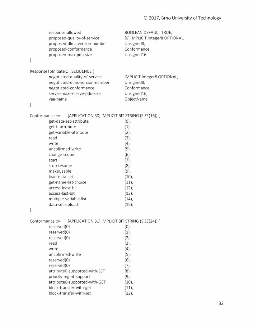
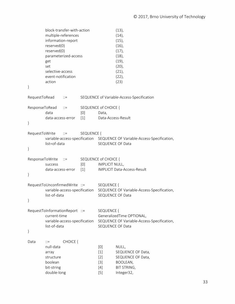
response-allowed BOOLEAN DEFAULT TRUE, proposed-quality-of-service [0] IMPLICIT Integer8 OPTIONAL, proposed-dlms-version-number Unsigned8, proposed-conformance Conformance, proposed-max-pdu-size Unsigned16 } ResponseToInitiate ::= SEQUENCE { negotiated-quality-of-service IMPLICIT Integer8 OPTIONAL, negotiated-dlms-version-number Unsigned8, negotiated-conformance Conformance, server-max-receive-pdu-size Unsigned16, vaa-name ObjectName } Conformance ::= [APPLICATION 30] IMPLICIT BIT STRING (SIZE(16)) { get-data-set-attribute (0), get-ti-attribute (1), get-variable-attribute (2), read (3), write (4), uncofirmed-write (5), change-scope (6), start (7), stop-resume (8), makeUsable (9), load-data-set (10), get-name-list-choice (11), access-least-bit (12), access-last-bit (13), multiple-variable-list (14), data-set-upload (15), } Conformance ::= [APPLICATION 31] IMPLICIT BIT STRING (SIZE(24)) { reserved(0) (0), reserved(0) (1), reserved(0) (2), read (3), write (4), uncofirmed-write (5), reserved(0) (6), reserved(0) (7), attribute0-supported-with-SET (8), priority-mgmt-support (9), attribute0-supported-with-GET (10), block-transfer-with-get (11), block-transfer-with-set (12),
© 2017, Brno University of Technology
33
block-transfer-with-action (13), multiple-references (14), information-report (15), reserved(0) (16), reserved(0) (17), parameterized-access (18), get (19), set (20), selective-access (21), event-notification (22), action (23) } RequestToRead ::= SEQUENCE of Variable-Access-Specification ResponseToRead ::= SEQUENCE of CHOICE { data [0] Data, data-access-error [1] Data-Access-Result } RequestToWrite ::= SEQUENCE { variable-access-specification SEQUENCE OF Variable-Access-Specification, list=of-data SEQUENCE OF Data } ResponseToWrite ::= SEQUENCE of CHOICE { success [0] IMPLICIT NULL, data-access-error [1] IMPLICIT Data-Access-Result } RequestToUnconfirmedWrite ::= SEQUENCE { variable-access-specification SEQUENCE OF Variable-Access-Specification, list-of-data SEQUENCE OF Data } RequestToInformationReport ::= SEQUENCE { current-time GeneralizedTime OPTIONAL, variable-access-specification SEQUENCE OF Variable-Access-Specification, list-of-data SEQUENCE OF Data } Data ::= CHOICE { null-data [0] NULL, array [1] SEQUENCE OF Data, structure [2] SEQUENCE OF Data, boolean [3] BOOLEAN, bit-string [4] BIT STRING, double-long [5] Integer32,
© 2017, Brno University of Technology
34
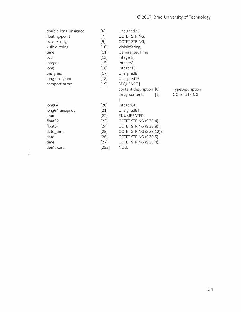
double-long-unsigned [6] Unsigned32, floating-point [7] OCTET STRING, octet-string [9] OCTET STRING, visible-string [10] VisibleString, time [11] GeneralizedTime bcd [13] Integer8, integer [15] Integer8, long [16] Integer16, unsigned [17] Unsigned8, long-unsigned [18] Unsigned16 compact-array [19] SEQUENCE { content-description [0] TypeDescription, array-contents [1] OCTET STRING } long64 [20] Integer64, long64-unsigned [21] Unsigned64, enum [22] ENUMERATED, float32 [23] OCTET STRING (SIZE(4)), float64 [24] OCTET STRING (SIZE(8)), date_time [25] OCTET STRING (SIZE(12)), date [26] OCTET STRING (SIZE(5)) time [27] OCTET STRING (SIZE(4)) don’t-care [255] NULL }
© 2017, Brno University of Technology
35
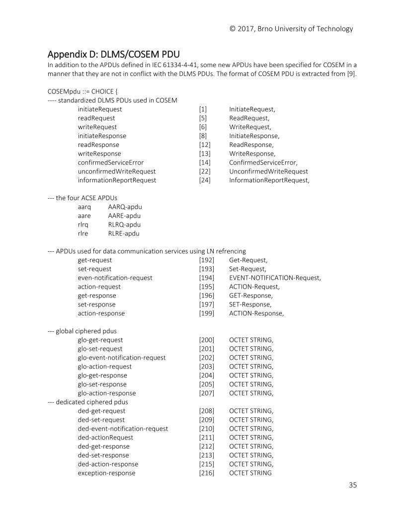
Appendix D: DLMS/COSEM PDU In addition to the APDUs defined in IEC 61334-4-41, some new APDUs have been specified for COSEM in a manner that they are not in conflict with the DLMS PDUs. The format of COSEM PDU is extracted from [9]. COSEMpdu ::= CHOICE { ---- standardized DLMS PDUs used in COSEM initiateRequest [1] InitiateRequest,
readRequest [5] ReadRequest, writeRequest [6] WriteRequest, initiateResponse [8] InitiateResponse, readResponse [12] ReadResponse, writeResponse [13] WriteResponse, confirmedServiceError [14] ConfirmedServiceError, unconfirmedWriteRequest [22] UnconfirmedWriteRequest informationReportRequest [24] InformationReportRequest,
--- the four ACSE APDUs aarq AARQ-apdu aare AARE-apdu rlrq RLRQ-apdu rlre RLRE-apdu --- APDUs used for data communication services using LN refrencing get-request [192] Get-Request, set-request [193] Set-Request, even-notification-request [194] EVENT-NOTIFICATION-Request, action-request [195] ACTION-Request, get-response [196] GET-Response, set-response [197] SET-Response, action-response [199] ACTION-Response, --- global ciphered pdus glo-get-request [200] OCTET STRING, glo-set-request [201] OCTET STRING, glo-event-notification-request [202] OCTET STRING, glo-action-request [203] OCTET STRING, glo-get-response [204] OCTET STRING, glo-set-response [205] OCTET STRING, glo-action-response [207] OCTET STRING, --- dedicated ciphered pdus ded-get-request [208] OCTET STRING, ded-set-request [209] OCTET STRING, ded-event-notification-request [210] OCTET STRING, ded-actionRequest [211] OCTET STRING, ded-get-response [212] OCTET STRING, ded-set-response [213] OCTET STRING, ded-action-response [215] OCTET STRING, exception-response [216] OCTET STRING

© 2017, Brno University of Technology
36
}
© 2017, Brno University of Technology
37
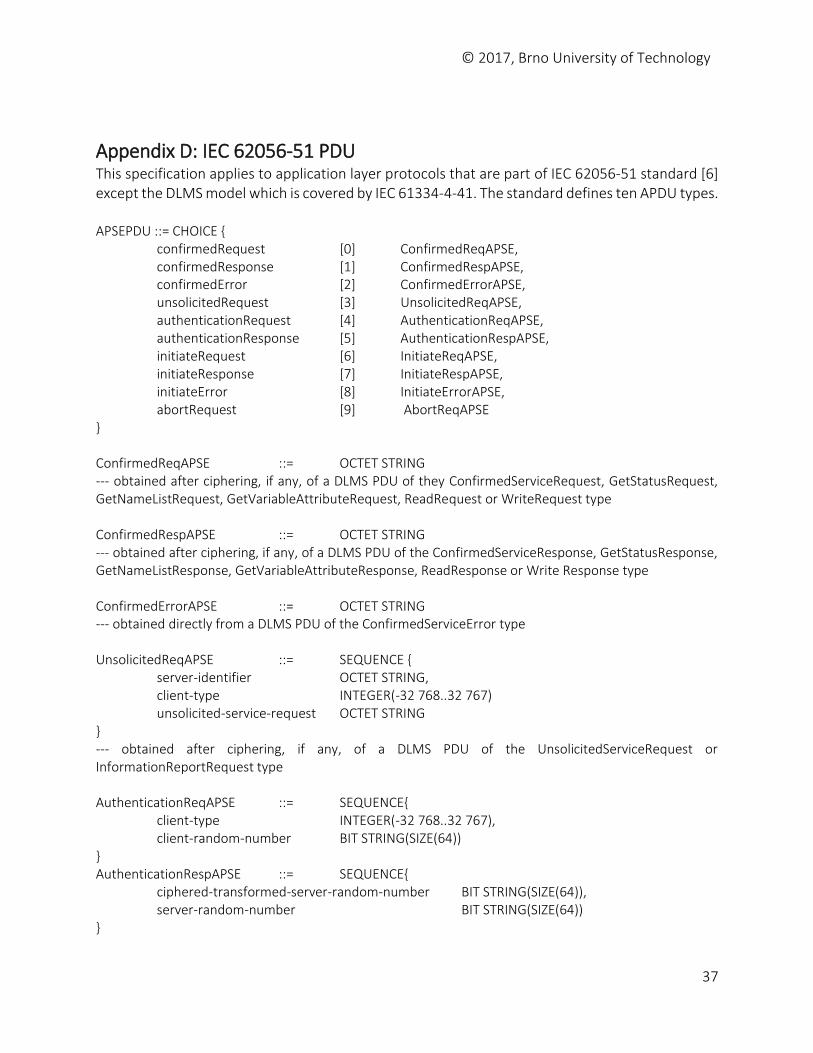
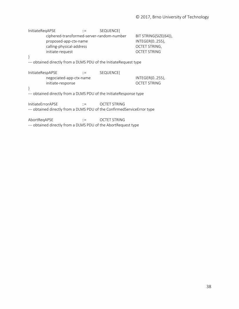
Appendix D: IEC 62056-51 PDU This specification applies to application layer protocols that are part of IEC 62056-51 standard [6] except the DLMS model which is covered by IEC 61334-4-41. The standard defines ten APDU types. APSEPDU ::= CHOICE { confirmedRequest [0] ConfirmedReqAPSE, confirmedResponse [1] ConfirmedRespAPSE, confirmedError [2] ConfirmedErrorAPSE, unsolicitedRequest [3] UnsolicitedReqAPSE, authenticationRequest [4] AuthenticationReqAPSE, authenticationResponse [5] AuthenticationRespAPSE, initiateRequest [6] InitiateReqAPSE, initiateResponse [7] InitiateRespAPSE, initiateError [8] InitiateErrorAPSE, abortRequest [9] AbortReqAPSE } ConfirmedReqAPSE ::= OCTET STRING --- obtained after ciphering, if any, of a DLMS PDU of they ConfirmedServiceRequest, GetStatusRequest, GetNameListRequest, GetVariableAttributeRequest, ReadRequest or WriteRequest type ConfirmedRespAPSE ::= OCTET STRING --- obtained after ciphering, if any, of a DLMS PDU of the ConfirmedServiceResponse, GetStatusResponse, GetNameListResponse, GetVariableAttributeResponse, ReadResponse or Write Response type ConfirmedErrorAPSE ::= OCTET STRING --- obtained directly from a DLMS PDU of the ConfirmedServiceError type UnsolicitedReqAPSE ::= SEQUENCE { server-identifier OCTET STRING, client-type INTEGER(-32 768..32 767) unsolicited-service-request OCTET STRING } --- obtained after ciphering, if any, of a DLMS PDU of the UnsolicitedServiceRequest or InformationReportRequest type AuthenticationReqAPSE ::= SEQUENCE{ client-type INTEGER(-32 768..32 767), client-random-number BIT STRING(SIZE(64)) } AuthenticationRespAPSE ::= SEQUENCE{ ciphered-transformed-server-random-number BIT STRING(SIZE(64)), server-random-number BIT STRING(SIZE(64)) }
© 2017, Brno University of Technology
38
InitiateReqAPSE ::= SEQUENCE{ ciphered-transformed-server-random-number BIT STRING(SIZE(64)), proposed-app-ctx-name INTEGER(0..255), calling-physical-address OCTET STRING, initiate-request OCTET STRING } --- obtained directly from a DLMS PDU of the InitiateRequest type InitiateRespAPSE ::= SEQUENCE{ negociated-app-ctx-name INTEGER(0..255), initiate-response OCTET STRING } --- obtained directly from a DLMS PDU of the InitiateResponse type InitiateErrorAPSE ::= OCTET STRING --- obtained directly from a DLMS PDU of the ConfirmedServiceError type AbortReqAPSE ::= OCTET STRING --- obtained directly from a DLMS PDU of the AbortRequest type