Embed Size (px)
Citation preview

MultiCraft
International Journal of Engineering, Science and Technology
Vol. 3, No. 8, 2011, pp. 142-155
INTERNATIONAL JOURNAL OF
ENGINEERING, SCIENCE AND TECHNOLOGY
www.ijest-ng.com
© 2011 MultiCraft Limited. All rights reserved
Analysis of disc brake squeal using a ten-degree-of-freedom model
Ibrahim Ahmed*
*Department of Automotive Technology, Faculty of Industrial Education, Helwan University, Cairo, EGYPT
*Corresponding Author: e-mail: [email protected] Tel +20-100-5869957
Abstract Disc brake squeal is considered as a highly main source of discomfort for passengers. It is also considered to be a high frequency noise when it is bigger than 1 kHz audible vibration of braking components. It is a significant problem in passenger vehicles that has not been solved satisfactorily until recently. Many manufacturers of brake pad materials spend up to fifty percent of their engineering budgets on noise, vibration and harshness (NVH) issues. Squeal noise is strongly correlated to the squeal index and degree of instability of the brake system assembly. Decreasing this squeal noise to some extent during braking is a very important matter for the comfort of passengers. So, a mathematical prediction model of 10-degree-of-freedom has been developed to study the effect of different brake components parameters on the degree of instability and squeal index of the brake system. The model has considered such factors as the distance between clamping bolts of the caliper, width and thickness of the friction material, which were not fully covered previously besides some other factors. Complex eigenvalue analysis by analytical program has been used to predict the unstable frequencies in the ventilated disc brake system assembly. It is evident from the analysis that Young’s moduli of the rotor and friction material have a great effect on the occurrence of squeal. The harder the friction material the bias of the brake to squeal. It is shown also that the squeal noise of the brake decreases with increasing semi-distance between the clamping bolts of the caliper to be at optimum value between 50-70 mm. However increasing the friction material thickness to 11 mm decreases the squeal index and instability of the system. The results have show that the predicted squeal tendency at varying all the studies parameters is as less as possible to be 43 % compared to other single parameters. Keywords: Ventilated disc brake, brake squeal, squeal index, degree of instability, eigen frequency. DOI: http://dx.doi.org/10.4314/ijest.v3i8.12 1. Introduction Since vehicle comfort has become an important factor to indicate the quality of a passenger car, so, eliminating or reducing the noise and vibration of a vehicle structure and system seems to provide a leading edge in the market to vehicle manufacturers (Lin et al., 2009). The noise does not affect brake operation, but the problem which occurs in cars, trucks and buses leads to needless replacement of brake pads and the addition of shims, damping materials and other parts designed to stop the noise. Many manufacturers of brake pad materials spend up to 50% of their engineering budgets on noise, vibration and harshness (NVH) issues (Kinkaid et al., 2003). Generally in disc brakes, squeal can occur when the brake pads contact the rotor while the vehicle is moving at low speeds, setting up a vibration that manifests itself as an annoying high-pitched squeal. The theory of vehicle brake squeal attracted attention many years ago because of the complex dynamic problem during the duty of the brake. Many researchers in their studies on the dynamics of brake system tried to reduce squeal by changing the factors associated with the brake squeal or modifying the brake rotor experimentally and theoretically. For example, Gouya and Nishiwaki (1990) studied the low frequency groan of the brake that occurs due to the increase in the disc temperature. It was observed that the groan noise is an oscillatory phenomenon, which occurs from the effect of vibrations on the friction force between a disc and a pad during coupling of two rotational vibrations of a disc caliper. Nishiwaki et al. (1989) studied the squeal experimentally and theoretically by modifying the disc (rotor) to eliminate brake squeal that occurred by self-excited vibration. The vibration modes during brake
Ahmed / International Journal of Engineering, Science and Technology, Vol. 3, No. 8, 2011, pp. 142-155
143
squeal generation at 6.32 kHz and 8.25 kHz were visualized by Holographic Interferometry. However, the conventional disc (rotor) vibrates at the maximum amplitude in the area excited artificially. Liles (1989) found that shorter pads, damping, softer disc and stiffer back plate could reduce squeal whilst in contrast, higher friction coefficient and wear of the friction material were prone to squeal. Lee et al. (1998) reported that reducing back plate thickness led to less uniform of contact pressure distributions and consequently increasing the squeal propensity. Hu et al. (1999) found the optimal design of experiments analysis was the one that used the original finger length, the vertical slot, the chamfer pad, the 28mm thickness of disc, and the 10mm thickness of friction material. Brooks et al. (1993) found that shifting the pistons away from the leading edge of the brake pads the system could destabilize the brake system. It was also predicted that the unstable system was due to the coupling of translational and rotational modes of the disc particularly at high values of pad stiffness. Shin et al. (2002) have shown that the damping of the pad and the disc were important in reducing instability. Their analysis also has shown and confirmed that increasing damping of either the disc or the pad alone could potentially destabilize the system. Liu et al. (2007) found that the squeal can be reduced by decreasing the friction coefficient, increasing the stiffness of the disc, using damping material on the back of the pads and modifying the shape of the brake pads. Dai and Lim (2008) have shown that the design of the pads with a radial chamfer possesses the least number of unstable modes, which implies lesser tendency towards squeal. Saad et al. (2008) and Ahmed et al. (2009) have shown the effect of disc and pad surface modification by adding a slot in the middle of the pad had a great effect on the reducing of the brake squeal through the escape of the wear particle via this slot. A number of issues have come to light to solve the problem of the brake squeal noise but it has not been solved satisfactory yet. The squeal of the disc brake has been studied experimentally by installing accelerometers on the back-plate of the pad. It was observed that the higher the coefficient of friction, the more the rotor squeals (Ichiba and Nagasawa, 1993). A brake dynamometer was used also to study the brake squeal by knowing the intensity and duration of the squeal and also the frequency range of the squeal. In this study, the pressure, temperature, and speed ranges were fully controlled during the occurrence of the squeal (Bracken and Sakioka, 1982). Earles and Chambers (1988) dealt with the squeal as not a serious problem considering that the squealing brake provides more effective braking than a non-squealing brake. It was concluded that increasing disc damping and allowing a decrease in rotor stiffness would appear to produce the most benefit of decreasing the squeal noise generation. Millner (1978) dealt with the squeal theoretically by studying the first eight disc mode instabilities at μ (coefficient of friction) less than 0.5 by building a multi degree of freedom mathematical model. The lower value of linear stiffness of the caliper of 318 MNm-1 to give instability was obtained at the third mode. The effect of negative friction-speed slope on the brake squeal was analyzed by Yuan (1995) who established a finite element model for the disc brake squeal. It was concluded that the brake squeal occurred due to the coupled vibrations of the brake system even if the negative μ-speed slope does not exist. The squeal propensity increased with the friction level when the negative μ-speed slope is absent and increasing the steel back-plate thickness and also lining thickness might reduce the squeal propensity. In a separate piece of work a new system was developed to stop the squeals by Nishizawa et al. (1997) by evaluating the electronic control cancelling for the noise (ECCN) with the test vehicle. The ECCN was installed in both front calipers to stop the frequency squeals (2-4 KHz) by decreasing the rotor vibration electronically on both the noise dynamometer and the test vehicle. Carne and Dohrmann (1998) studied the effect of the support stiffness and damping conditions on the measured modal parameters as frequencies and damping ratios. It was realized that the increase of the measured frequency of the supported system was related to the square of the frequency ratio of the rigid body mode and the elastic mode. This paper is focusing on decreasing the squeal of the ventilated fixed caliper disc brake because most of previous literature in their theoretical studies dealt with the plain and floating caliper disc brake using a maximum of eight-degree-of-freedom models. The designed model has taken such factors as the distance between clamping bolts of the caliper, weight of the caliper and thicknesses of the rotor rings that were not fully covered in most literature. In addition to some other factors such as width, thickness and Young’s modulus of the friction material and rotor that can affect the brake stability and consequently brake squeal noise. 2. Analytical Model of the Ventilated Disc Brake Squeal Noise In the fixed caliper disc brake type, the caliper piston presses the right (inner) and left (outer) pads towards the ventilated rotor at the same time as shown in Figure 1. So, a lag could be occurring between the two pads at pressing on the rotor and it is assumed that the forces occur at the same time and there is a fully contact between the pads and the rotor. A theoretical 10-degree-of-freedom mathematical model has been developed in this study depending on the theoretical model of North (1972) and Millner (1978) who are the pioneers of dealing with the brake squeal mathematically and also the model of Wagner et al. (2004) as well as Neubauer and Kröger (2008) who control the brake squeal through the smart pads. This mathematical model stresses mainly on changing some brake parameters properties in order to find a formula valid for minimizing the brake squeal as less as possible as clear later.
Ahmed / International Journal of Engineering, Science and Technology, Vol. 3, No. 8, 2011, pp. 142-155
144
Figure 1. Ventilated disc brake rotor (IP, 2012).
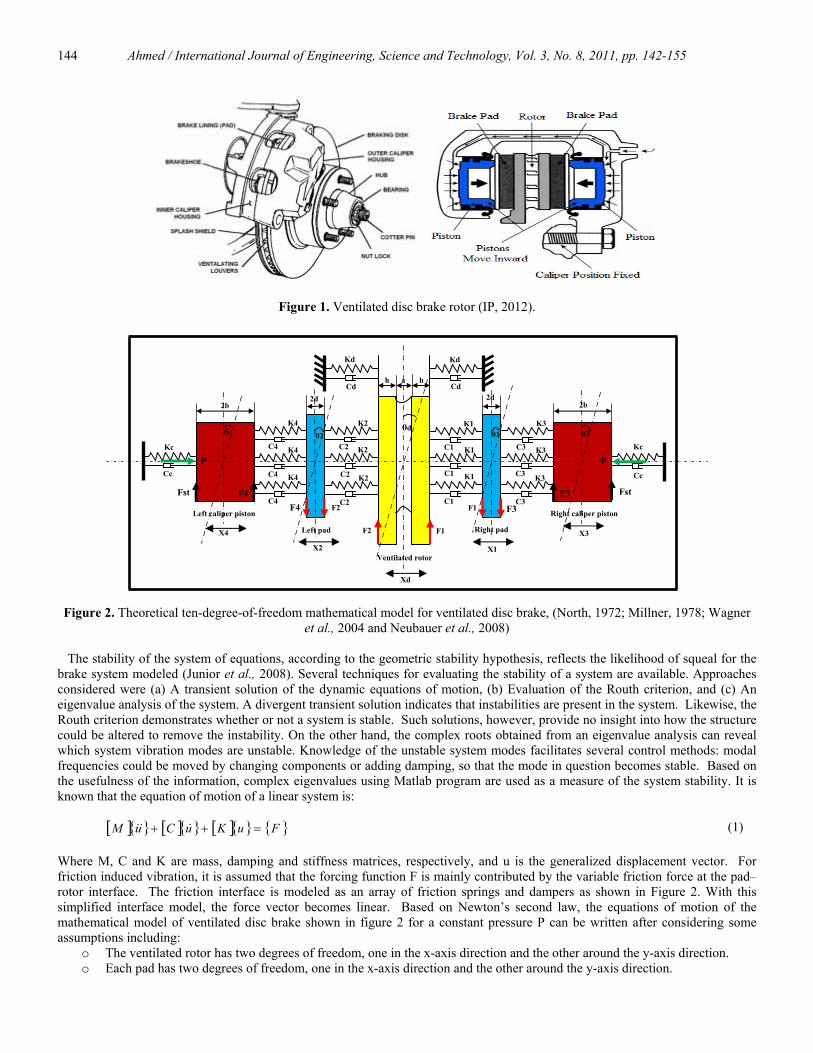
Figure 2. Theoretical ten-degree-of-freedom mathematical model for ventilated disc brake, (North, 1972; Millner, 1978; Wagner
et al., 2004 and Neubauer et al., 2008) The stability of the system of equations, according to the geometric stability hypothesis, reflects the likelihood of squeal for the brake system modeled (Junior et al., 2008). Several techniques for evaluating the stability of a system are available. Approaches considered were (a) A transient solution of the dynamic equations of motion, (b) Evaluation of the Routh criterion, and (c) An eigenvalue analysis of the system. A divergent transient solution indicates that instabilities are present in the system. Likewise, the Routh criterion demonstrates whether or not a system is stable. Such solutions, however, provide no insight into how the structure could be altered to remove the instability. On the other hand, the complex roots obtained from an eigenvalue analysis can reveal which system vibration modes are unstable. Knowledge of the unstable system modes facilitates several control methods: modal frequencies could be moved by changing components or adding damping, so that the mode in question becomes stable. Based on the usefulness of the information, complex eigenvalues using Matlab program are used as a measure of the system stability. It is known that the equation of motion of a linear system is:
[ ]{ } [ ]{ } [ ]{ } { }FuKuCuM =++ &&& (1) Where M, C and K are mass, damping and stiffness matrices, respectively, and u is the generalized displacement vector. For friction induced vibration, it is assumed that the forcing function F is mainly contributed by the variable friction force at the pad–rotor interface. The friction interface is modeled as an array of friction springs and dampers as shown in Figure 2. With this simplified interface model, the force vector becomes linear. Based on Newton’s second law, the equations of motion of the mathematical model of ventilated disc brake shown in figure 2 for a constant pressure P can be written after considering some assumptions including:
o The ventilated rotor has two degrees of freedom, one in the x-axis direction and the other around the y-axis direction. o Each pad has two degrees of freedom, one in the x-axis direction and the other around the y-axis direction.
F3
Fst
Ventilated rotor
C2 Left caliper piston
Right pad
Right caliper piston
Left pad F2 F1
X1
Xd
K4
K4
K4
C4
C4
C4
θd
2d 2b 2b
h a h
2d
Kc
Kd Kd
Cd Cd
Cc
Kc
C1 C3
K1 K3 K2
X3
X2
X4
Cc
F1 F2
K2
K2 C2
C2 K1
K1 C1
C1 K3
K3 C3
C3
θ4 θ2 θ3 θ1
Fst F4
F4
F3
P P
Ahmed / International Journal of Engineering, Science and Technology, Vol. 3, No. 8, 2011, pp. 142-155
145
o Each piston has two degrees of freedom, one in the x-axis direction and the other around the y-axis direction. o The contact forces F1, F2, F3 and F4 are parallel to the face of the rotor, pads and pistons as shown in Figure 2 and will
be activated during the contact between the pads and the rotor. o The rotor and the pads vibrate in the same mode.
The equations of motion of the system due to displacements 321 , , , xxxxd and 4x respectively are summarized as follow:
0).21( ..K - ).( .C - .C - ).(. 221121221121
=++−++++++
d
dDdDdd
θFFxKxxKKKxxxCCCxM &&&&&
(2) 0).31(.).(..).(.. 133131133131111 =−+−++−−++− θFFxKxKKxKxCxCCxCxM dd &&&&& (3)
0).42(.).(..).(.. 244242244242222 =−+−++−−++− θFFxKxKKxKxCxCCxCxM dd &&&&& (4) 0).3(.).(.).(. 3133313333 =++−++−++ θFstFxKxKcKxCxCcCxM C &&&& (5)
0).4(.).(.).(. 4244424444 =++−++−++ θFstFxKxKcKxCxCcCxM C &&&& (6) The equations of motion of the system due to rotations 321 , , , θθθθd and 4θ respectively are summarized as follow:
0)2
).(21(
..).(..).(. 261565261565
=+++
−−+++−−+++ahFF
θKθKθKKKθCθCθCCCθI dDRdDRdd&&&&&
(7)
0).31(..2...2.. 351553515511 =+−−+−−+− dFFθKθKθKθCθCθCθI dd&&&&& (8)
0).42(..2...2.. 462664626622 =+−−+−−+− dFFθKθKθKθCθCθCθI dd&&&&& (9)
0).3().(.).(.. 3717371733 =++++−++− bFstFθKKθKθCCθCI RCRC&&&&θ (10)
0).4().(.).(.. 4828482844 =++++−++− bFstFθKKθKθCCθCI RCRC&&&&θ (11)
Where
F1 = μ. R1 = ( ) ( )[ ].... 1111 xxKxxCF ddst −+−+ &&μ (12) F2 = μ. R2 = ( ) ( )[ ].... 2222 xxKxxCF ddst −+−+ &&μ (13) F3 = μ. R3 = ( ) ( )[ ].... 133133 xxKxxCFstb −+−+ &&μ (14) F4 = μ. R4 = ( ) ( )[ ].... 244244 xxKxxCFstb −+−+ &&μ (15)
The equations from (2) to (11) can be rewritten in the form of:
[ ] [ ] [ ] [ ] [ ] [ ] [ ] 0 .mk . =++ xxmcx &&& (16)
[ ] [ ][ ] [ ][ ] 0 . ...2 2 =++ xxx nn ωωζ &&& (17) Where nω is the natural frequency of the system. ζ is the damping ratio or viscous damping factor and equal to ζ=c/2.m. nω
We assume the solutions of the form:
xd =Ad.eλt θd =B. eλt due to disc displacement and rotation. x1 =C. eλt θ1 =D. eλt due to right pad displacement and rotation. x2 =E. eλt θ2 =F. eλt due to left pad displacement and rotation. x3 =G. eλt θ3 =H. eλt due to right caliper piston displacement and rotation. x4 =I. eλt θ4 =J. eλt due to left caliper piston displacement and rotation.
Ahmed / International Journal of Engineering, Science and Technology, Vol. 3, No. 8, 2011, pp. 142-155
146
And by substitution in the main equation, the characteristic equation can be expressed in the following form: 0...2 22 =++ nn ωλωζλ (18)
And the roots of this equation will appear as a complex conjugate pairs as follows: )12
1 ).(.(n −+−= ζζωλ and )122 ).(.(n −−−= ζζωλ
The displacement can be also rewritten as a damped sinusoidal wave in the form of:
{ } { } teu tii
ii cos ωφ σ= (19)
Thus, iσ and iω are the damping coefficient and damped natural frequency describing damped sinusoidal motion. There are three categories of damped motion:
• If the damping coefficient is negative, the system will decay in a short time and the solution will be in the form of : )( sine . t- ψωζω += tAx ddd (20)
Where )1( 2ζωω −= nd . (21)
• A positive damping coefficient, however, causes the amplitude of oscillations to increase with time. The roots of the solution will be negative real numbers and the system will decay without oscillation for a long period, therefore the system is not stable when the damping coefficient is positive.
• If the damping coefficient is equal to 1, it is called a critically damped, the roots of the solution will be negative real numbers equals to nζω− and the solution will be in the form tetAAx ω−+= )..21( . The system will decay in relating long time and the motion will be non-periodic.
By examining the real part of the system eigenvalues the modes that are unstable and likely to produce squeal are revealed. Generally, disc brake squeal is caused by unstable vibrations of the brake system. A Matlab program is used to determine if the brake system will squeal or not by checking the stability of the ventilated disc brake assembly. This program is able to carry out the eigenvalue analysis that can indicate the instability level and the natural frequency. The corresponding eigenvalue problem will be in the form of [ ] [ ] 0)( =− IA λdet . Each eigenvalue λ is a complex number that contains two parts as mentioned previously. The first part is real and the second part is imaginary. When the real part is negative, this indicates that the mode is damped and stable and when the real part is positive, it means that the mode is not stable and the damping is negative. Rearranging these equations (2-11) to be as in the form of equation (1); the mass matrix [M] will be in the form of:
[ ] .
I 0 0 0 0 0 0 0 0 00 M 0 0 0 0 0 0 0 00 0 I 0 0 0 0 0 0 00 0 0 M 0 0 0 0 0 00 0 0 0 I 0 0 0 0 00 0 0 0 0 M 0 0 0 00 0 0 0 0 0 I 0 0 00 0 0 0 0 0 0 M 0 00 0 0 0 0 0 0 0 I 00 0 0 0 0 0 0 0 0
4
4
3
3
2
2
1
1
d
d
⎥⎥⎥⎥⎥⎥⎥⎥⎥⎥⎥⎥⎥⎥
⎦
⎤
⎢⎢⎢⎢⎢⎢⎢⎢⎢⎢⎢⎢⎢⎢
⎣
⎡
=
M
M
Ahmed / International Journal of Engineering, Science and Technology, Vol. 3, No. 8, 2011, pp. 142-155
147
And the damping matrix [C] will be in the form of:
[ ] .
)C(C 0 0 0 C- 0 0 0 0 00 Cc)(C 0 0 0 C- 0 0 0 00 0 )C(C 0 0 0 C- 0 0 00 0 0 Cc)(C 0 0 0 C- 0 0C- 0 0 0 2C 0 0 0 C- 00 C- 0 0 0 )C(C 0 0 0 C2-0 0 C 0 0 0 2C 0 C- 00 0 0 C- 0 0 0 )( 0 C1-0 0 0 0 C- 0 C- 0 )CC(C 00 0 0 0 0 C- 0 C- 0 )(
RC88
44
RC77
33
666
442
551
331
65DR65
2121
⎥⎥⎥⎥⎥⎥⎥⎥⎥⎥⎥⎥⎥⎥
⎦
⎤
⎢⎢⎢⎢⎢⎢⎢⎢⎢⎢⎢⎢⎢⎢
⎣
⎡
++
++
+
+++
++
=
CC
CCC
C
D
And the stiffness matrix [K] will be in the form of:
[ ] .
)K(K 0 0 0 K- 0 0 0 0 0Fst)(F4 c)(K 0 0 0 K- 0 0 0 0
0 0 )(K 0 0 0 K- 0 0 00 0 Fst)(F3 c)(K 0 0 0 K- 0 0K- 0 0 0 2K 0 0 0 K- 00 K- 0 0 F4)(F2 )K(K 0 0 0 K-0 0 K 0 0 0 2K 0 K- 00 0 0 K- 0 0 F3)-(F1 )( 0 K-0 0 0 0 K- 0 K- 0 )(K 00 0 0 0 0 K- 0 K- F2)(F1 )(
RC88
44
77
33
666
4422
555
331 1
65DR65
2 121
⎥⎥⎥⎥⎥⎥⎥⎥⎥⎥⎥⎥⎥⎥
⎦
⎤
⎢⎢⎢⎢⎢⎢⎢⎢⎢⎢⎢⎢⎢⎢
⎣
⎡
+++
+++
++
++++++
=
KK
K
KKKK
KKK
K
RC
D
From the eigenvalues analysis, the instability levels and the eigenfrequencies are calculated. The instability level (degree of instability) is defined as the real part of the eigenvalue α =Re [λ] and the eigenfrequency is defined as the imaginary part of the eigenvalue ω =Im[λ] Hz. Some authors took the instability level as a squeal propensity and others do not. In this work the squeal propensity (σ) that is the squeal index will be taken as ( ) ( )2/sin.2/122 δωασ += as Millner’s, (1978) assumption and the results agree with it. The eigen frequencies will be taken as ω/2π Hz. Where δ is the phase angle.
⎟⎟⎠
⎞⎜⎜⎝
⎛= −
part RealpartImaginary tan 1δ (22)
By substitution of the matrices by the data given in Table 1 and rearranging the equations of motion (2-11), it will lead to the state space method as shown in the next form of:
X& = AX + Bu. (23) Y = CX + Du. (24)
Where A is the System 20×20 matrix. B is the Input 20×1 matrix. C is the Output 10×20. X is the System State 20-vector. u is the Input vector. And by examining the real part of the system eigenvalues using MATLAB program, the modes that are unstable and likely to produce squeal are revealed.
Ahmed / International Journal of Engineering, Science and Technology, Vol. 3, No. 8, 2011, pp. 142-155
148
Table 1. Ventilated disc brake rotor and pad specifications.
Properties and dimensions Ventilated disc Properties and dimensions Pad (friction material Young’s modulus, Ed Density, ρ Poisson’s ratio, ν Coefficient of friction, μ Rings inner radius, ri Rings outer radius, ro Lower ring thickness, h Upper ring thickness, h Hub inner radius, hi Hub outer radius, ho Hub thickness, ht Hub length, lh Fins thickness, a
195 GN/m2 7600 kg/m3 0.27 0.42 70 mm 128 mm 7 mm 8 mm 32 mm 70 mm 6 mm 22.4 mm 8 mm
Young’s modulus, Ep Density, ρp Poisson’s ratio, ν Coefficient of friction, μ Backplate length, Backplate thickness, Backplate width, Abutment width, Abutment length, Friction material length, l Friction material thickness, 2d Friction material width, w
900 MN/m2 2600 kg/m3 0.23 0.42 128 mm 5 mm 48 mm 10 mm 8 mm 110 mm 10 mm 44 mm
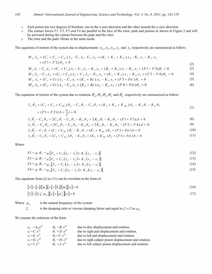
3. Results and Discussions Figure 3 indicates the effect of the Young’s modulus of the ventilated rotor on brake squeal noise and degree of instability. The modulus of elasticity of the ventilated brake rotor is increased from 50 to 250 GN/m2. It can be noted from the figure that as the Young’s modulus of the rotor increases from 50 to 100 GN/m2 the squeal index decreases from 148 to 85 and when the Young’s modulus of the rotor increases from 100 to 250GN/m2 the squeal index increase from 85 to 105 giving the best value between 90 and 130 GN/m2. The maximum squeal index of 148 happened with a low modulus of elasticity of 50 GN/m2 and the lower value of squeal index of 85 and 89 occurred at a rotor Young’s modulus of 90 and 130 GN/m2 respectively. The maximum frequency of 7250 Hz is at rotor Young’s modulus of 50 GN/m2 decreases to 2600 Hz at 100 GN/m2 and then decreases again to be 4300 Hz at rotor Young’s modulus of 250 GN/m2. However the maximum instability of 118 (Real Part) is predicted at rotor Young’s modulus of 50 GN/m2 as shown clearly in figure 3. This is to confirm the need for a mean value of the rotor Young’s modulus to compromise between the performance of the brake and the squeal occurrence.
0
40
80
120
160
50
75
100
125
150
0 50 100 150 200 250 300
Deg
ree
of
Inst
abil
ity
Sq
uea
l In
dex
Young's Modulus of the ventilated disc (GN/m2)
Squeal index
degree of instability
0
2
4
6
8
0 50 100 150 200 250 300
Freq
uenc
y, k
Hz.
Young's Modulus of the ventilated disc (GN/m2)
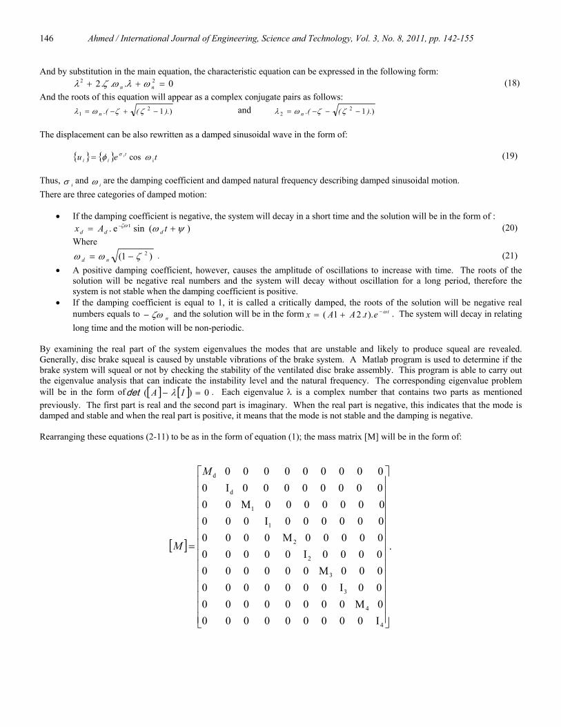
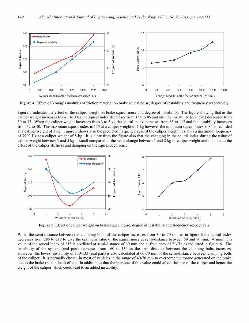
Figure 3. Effect of Young’s modulus of brake rotor on brake squeal noise, degree of instability and frequency respectively. Figure 4 indicates the effect of the Young’s modulus of the friction material on brake squeal noise and degree of instability. The figure shows that as the Young’s modulus of the friction material increases from 100 MN/m2 to 1200 MN/m2 the squeal index increases from 198 to 258 however, the degree of instability increase from 23 to 70. The maximum squeal index 258 occurred at a high modulus of elasticity of 1200 MN/m2 and the lowest value of squeal index of 198 is predicted at modulus of elasticity of 100 MN/m2. A frequency of 8500 Hz is predicted at a friction material Young’s modulus of 100 MN/m2 and a maximum frequency of 11 kHz reaches at a friction material Young’s modulus of 1200 MN/m2 as indicated clearly in figure 4 at a maximum instability of 70 (Real Part). This curves confirmed the need to some extent for a softer friction material to match between the instability of the brake with the frictional behavior of the pad.
Ahmed / International Journal of Engineering, Science and Technology, Vol. 3, No. 8, 2011, pp. 142-155
149
20
40
60
80
180
200
220
240
260
0 200 400 600 800 1000 1200 1400
Deg
ree
of
inst
abil
ity
Sq
uea
l In
dex
Young's Modulus of the friction material (MN/m2)
Squeal Index
Degree of Instability
6
8
10
12
0 200 400 600 800 1000 1200 1400
Freq
uenc
y, k
Hz.
Young's Modulus of the friction material (MN/m2)
Figure 4. Effect of Young’s modulus of friction material on brake squeal noise, degree of instability and frequency respectively.
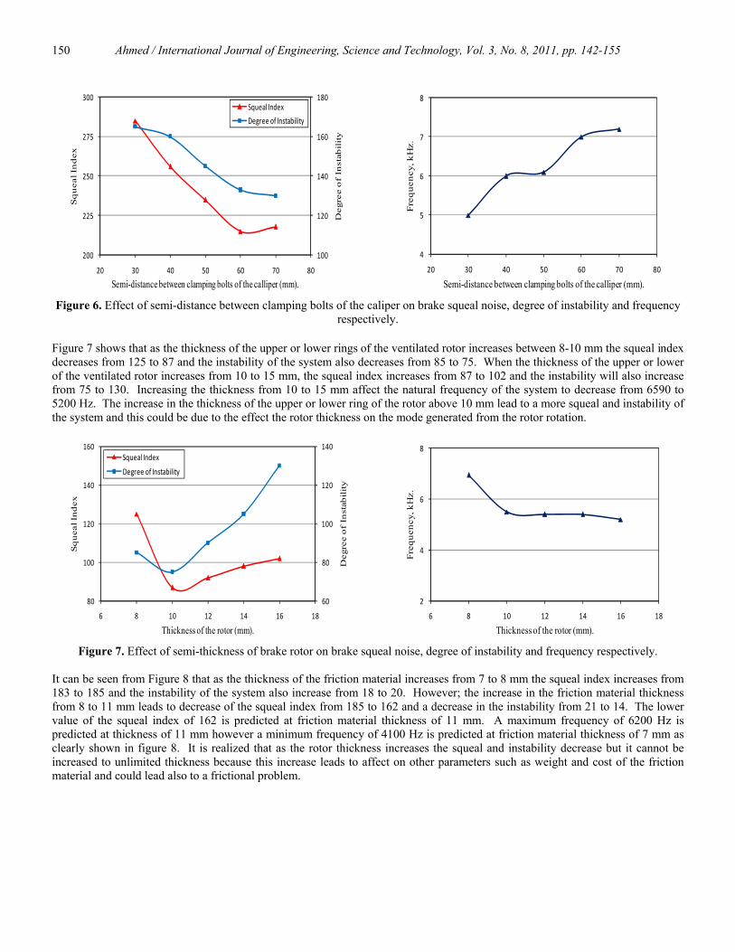
Figure 5 indicates the effect of the caliper weight on brake squeal noise and degree of instability. The figure showing that as the caliper weight increases from 1 to 3 kg the squeal index decreases from 155 to 85 and also the instability (real part) decreases from 50 to 32. When the caliper weight increases from 3 to 5 kg the squeal index increases from 85 to 112 and the instability increases from 32 to 40. The maximum squeal index is 155 at a caliper weight of 1 kg however the minimum squeal index is 85 is recorded at a caliper weight of 3 kg. Figure 5 shows also the predicted frequency against the caliper weight, it shows a maximum frequency of 7900 Hz at a caliper weight of 5 kg. It is clear from the figure also that the changing in the squeal index during the using of caliper weight between 3 and 5 kg is small compared to the same change between 1 and 2 kg of caliper weight and this due to the effect of the caliper stiffness and damping on the squeal occurrence.
20
30
40
50
60
80
100
120
140
160
0 1 2 3 4 5 6
Deg
ree
of
Inst
abil
ity
Sq
uea
l In
dex
Weight of the calliper (kg).
Squeal Index
Degree of Instability
4
5
6
7
8
0 1 2 3 4 5 6
Freq
uenc
y, k
Hz.
Weight of the calliper (kg).
Figure 5. Effect of caliper weight on brake squeal noise, degree of instability and frequency respectively.
When the semi-distance between the clamping bolts of the caliper increases from 30 to 70 mm as in figure 6 the squeal index decreases from 285 to 218 to give the optimum value of the squeal noise at semi-distance between 50 and 70 mm. A minimum value of the squeal index of 215 is predicted at semi-distance of 60 mm and at frequency of 7 kHz as indicated in figure 6. The instability of the system (real part) decreases from 160 to 130 as the semi-distance between the clamping bolts increases. However, the lowest instability of 130-133 (real part) is also calculated at 60-70 mm of the semi-distance between clamping bolts of the caliper. It is normally chosen in most of vehicles in the range of 40-70 mm to overcome the torque generated on the brake due to the brake (piston load) effect. In addition to that the increase of this value could affect the size of the caliper and hence the weight of the caliper which could lead to an added instability.
Ahmed / International Journal of Engineering, Science and Technology, Vol. 3, No. 8, 2011, pp. 142-155
150
100
120
140
160
180
200
225
250
275
300
20 30 40 50 60 70 80
Deg
ree
of
Inst
abil
ity
Sq
uea
l In
dex
Semi-distance between clamping bolts of the calliper (mm).
Squeal Index
Degree of Instability
4
5
6
7
8
20 30 40 50 60 70 80
Fre
qu
ency
, kH
z.
Semi-distance between clamping bolts of the calliper (mm).
Figure 6. Effect of semi-distance between clamping bolts of the caliper on brake squeal noise, degree of instability and frequency respectively.
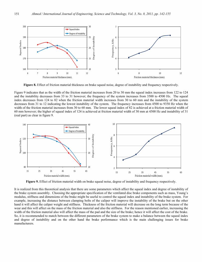
Figure 7 shows that as the thickness of the upper or lower rings of the ventilated rotor increases between 8-10 mm the squeal index decreases from 125 to 87 and the instability of the system also decreases from 85 to 75. When the thickness of the upper or lower of the ventilated rotor increases from 10 to 15 mm, the squeal index increases from 87 to 102 and the instability will also increase from 75 to 130. Increasing the thickness from 10 to 15 mm affect the natural frequency of the system to decrease from 6590 to 5200 Hz. The increase in the thickness of the upper or lower ring of the rotor above 10 mm lead to a more squeal and instability of the system and this could be due to the effect the rotor thickness on the mode generated from the rotor rotation.
60
80
100
120
140
80
100
120
140
160
6 8 10 12 14 16 18
Deg
ree
of
Inst
abil
ity
Sq
uea
l In
dex
Thickness of the rotor (mm).
Squeal Index
Degree of Instability
2
4
6
8
6 8 10 12 14 16 18
Freq
uenc
y, k
Hz.
Thickness of the rotor (mm).
Figure 7. Effect of semi-thickness of brake rotor on brake squeal noise, degree of instability and frequency respectively.
It can be seen from Figure 8 that as the thickness of the friction material increases from 7 to 8 mm the squeal index increases from 183 to 185 and the instability of the system also increase from 18 to 20. However; the increase in the friction material thickness from 8 to 11 mm leads to decrease of the squeal index from 185 to 162 and a decrease in the instability from 21 to 14. The lower value of the squeal index of 162 is predicted at friction material thickness of 11 mm. A maximum frequency of 6200 Hz is predicted at thickness of 11 mm however a minimum frequency of 4100 Hz is predicted at friction material thickness of 7 mm as clearly shown in figure 8. It is realized that as the rotor thickness increases the squeal and instability decrease but it cannot be increased to unlimited thickness because this increase leads to affect on other parameters such as weight and cost of the friction material and could lead also to a frictional problem.
Ahmed / International Journal of Engineering, Science and Technology, Vol. 3, No. 8, 2011, pp. 142-155
151
10
15
20
25
30
160
170
180
190
200
6 7 8 9 10 11 12
Deg
ree
of
Inst
abil
ity
Sq
uea
l In
dex
Friction material thickness (mm).
Squeal Index
Degree of Instability
3
4
5
6
7
6 8 10 12
Freq
uen
cy, k
Hz.
Friction material thickness (mm).
Figure 8. Effect of friction material thickness on brake squeal noise, degree of instability and frequency respectively. Figure 9 indicates that as the width of the friction material increases from 20 to 30 mm the squeal index increases from 122 to 124 and the instability decreases from 33 to 31 however; the frequency of the system increases from 3500 to 4500 Hz. The squeal index decreases from 124 to 82 when the friction material width increases from 30 to 60 mm and the instability of the system decreases from 31 to 12 indicating the lowest instability of the system. The frequency increases from 4500 to 9350 Hz when the width of the friction material increases from 30 to 60 mm. The lower squeal index of 82 is achieved at a friction material width of 60 mm however; the higher of squeal index of 124 is achieved at friction material width of 30 mm at 4500 Hz and instability of 31 (real part) as clear in figure 9.
10
20
30
40
80
100
120
140
15 25 35 45 55 65
Deg
ree
of
Inst
abil
ity
Sq
uea
l In
dex
Friction material width (mm).
Squeal Index
Degree of Instability
2
4
6
8
10
15 25 35 45 55 65
Fre
qu
ency
, kH
z.
Friction material width (mm).
Figure 9. Effect of friction material width on brake squeal noise, degree of instability and frequency respectively. It is realized from this theoretical analysis that there are some parameters which affect the squeal index and degree of instability of the brake system assembly. Choosing the appropriate specification of the ventilated disc brake components such as mass, Young’s modulus, stiffness and dimensions of the brake might be useful to control the squeal index and instability of the brake system. For example, increasing the distance between clamping bolts of the caliper will improve the instability of the brake but on the other hand it will affect the caliper weight and stiffness. Thickness of the friction material will decrease on the long term because of the wear and this will affect on the mass of the friction material and also the stiffness. For the reason mentioned earlier, increasing the width of the friction material also will affect the mass of the pad and the size of the brake; hence it will affect the cost of the brake. So, it is recommended to match between the different parameters of the brake system to make a balance between the squeal index and degree of instability and on the other hand the brake performance which is the main challenging issues for brake manufacturers.
Ahmed / International Journal of Engineering, Science and Technology, Vol. 3, No. 8, 2011, pp. 142-155
152
In terms of squeal tendency that is shown in the following formula:
∑ ⎟⎟⎠
⎞⎜⎜⎝
⎛×=
i
1000)(spart Imaginary
)(Spart RealTOI
i
i , (25)
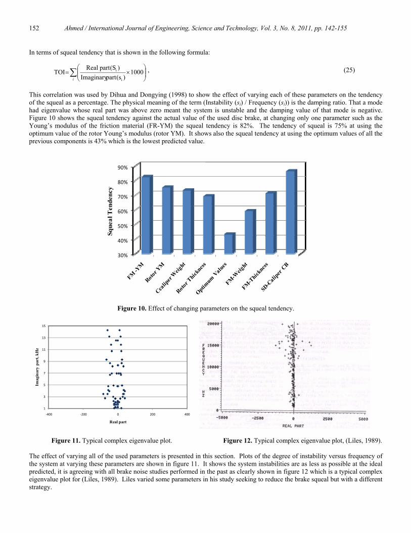
This correlation was used by Dihua and Dongying (1998) to show the effect of varying each of these parameters on the tendency of the squeal as a percentage. The physical meaning of the term (Instability (si) / Frequency (si)) is the damping ratio. That a mode had eigenvalue whose real part was above zero meant the system is unstable and the damping value of that mode is negative. Figure 10 shows the squeal tendency against the actual value of the used disc brake, at changing only one parameter such as the Young’s modulus of the friction material (FR-YM) the squeal tendency is 82%. The tendency of squeal is 75% at using the optimum value of the rotor Young’s modulus (rotor YM). It shows also the squeal tendency at using the optimum values of all the previous components is 43% which is the lowest predicted value.
30%
40%
50%
60%
70%
80%
90%
Sque
al T
ende
ncy
Figure 10. Effect of changing parameters on the squeal tendency.
1
3
5
7
9
11
13
15
‐400 ‐200 0 200 400
Imag
inar
y pa
rt, k
Hz
Real part
Figure 11. Typical complex eigenvalue plot. Figure 12. Typical complex eigenvalue plot, (Liles, 1989). The effect of varying all of the used parameters is presented in this section. Plots of the degree of instability versus frequency of the system at varying these parameters are shown in figure 11. It shows the system instabilities are as less as possible at the ideal predicted, it is agreeing with all brake noise studies performed in the past as clearly shown in figure 12 which is a typical complex eigenvalue plot for (Liles, 1989). Liles varied some parameters in his study seeking to reduce the brake squeal but with a different strategy.
Ahmed / International Journal of Engineering, Science and Technology, Vol. 3, No. 8, 2011, pp. 142-155
153
4. Conclusions
It is clear from this study that the analytical complex eigenvalue analysis of the ventilated disc brake systems is a very important tool to predict the generation tendency of brake to squeal which is still a very big challenging issue in the car industry and particularly the comfort of the passengers. Different design parameters such as the Young’s modulus, thickness of the rotor and friction material, and the width and weight of the friction material were used in this investigation to study their effect on brake squeal in the matter of squeal index and degree of instability. Other parameters were also taken into account in studying the squeal of the brake such as weight and semi-distance between the clamping bolts of the caliper. The following conclusions can be drawn. 1- In general, the unstable frequencies calculated by MATLAB program can help in minimizing the squeal tendency of the brake
system. 2- Increasing the Young’s modulus of the ventilated rotor will affect the system tendency to squeal behaviour and the optimum
value of the rotor Young’s modulus was between 90 and 130 GN/m2. The lowest squeal index of 85 and 89 occurred at a rotor Young’s modulus of 90 and 130 GN/ m2 respectively. However the maximum frequency reached during this change was 7250 Hz.
3- Increasing the Young’s modulus of the friction material will increase the squeal index of the brake system and hence will affect the system tendency to squeal. The lowest value of squeal index of 198 was recorded at modulus of elasticity of 100 MN/ m2. The maximum frequency reached was 11 kHz at a maximum degree of instability of 70 (Real Part). The harder the friction material, the bias of the brake to squeal.
4- When the caliper weight increases from 1 to 3 kg the squeal index (SI) decreases from 155 to 85 and when it increases from 3 to 5 kg the SI increases from 85 to 112. Increasing the semi-distance between the clamping bolts of the caliper will decrease the SI noise of the brake system assembly and also will decrease the degree of instability of the brake system.
5- Increasing or decreasing the semi-distance between clamping bolts of the calliper has a great effect on the tendency of squeal. Increasing the semi-distance from 30 to 70 mm decreases the squeal index from 285 to 218. The optimum semi-distance between clamping bolts of the calliper is 70 mm. It is recommended to be in the range of 40-70 mm because increasing this value affects the size and weight of the calliper and hence will affect the squeal occurrence.
6- The thickness of the upper or lower rings of the ventilated rotor has a major effect on the brake squeal index. The minimum squeal index of 87 happened with a rotor thickness 10 mm and frequency of 5500 Hz. When the thickness increases above 10 mm the squeal index will increase rapidly. The effect of the rotor thickness on the squeal index and instability is higher than the effect of the friction material thickness on the same parameters. A maximum squeal index of 185 corresponding to a friction material thickness of 8 mm while a minimum squeal index of 162 with corresponding to a friction material thickness of 11 mm.
7- However, the width of the friction material has also a major effect on the occurrence of the squeal noise of the brake assembly and as it is increases the squeal index increases. The lowest squeal index was 82 achieved with a friction material width of 60 mm and the higher squeal index of 124 was achieved at a friction material width of 30 mm at 4500 Hz.
8- The predicted squeal tendency at varying all the studies parameters is as less as possible to be 43 % compared to other single parameters.
Nomenclature a Rotor fins height b Semi-length of the caliper piston. C1 Linear damping between the rotor and the right pad. C2 Linear damping between the rotor and the left pad. C3 Linear damping between the right pad and right caliper piston. C4 Linear damping between the left pad and the left caliper piston. CD Linear damping of the rotor. Cc Linear damping of caliper. C5 Rotary damping of the right pad. C6 Rotary damping of the left pad. C7 Rotary damping of the right caliper piston. C8 Rotary damping of the left caliper piston. CRD Rotary damping of the rotor. CRC Rotary damping of the caliper. d Semi-thickness of the pad. Ed Young’s modulus of the disc (rotor).
Ahmed / International Journal of Engineering, Science and Technology, Vol. 3, No. 8, 2011, pp. 142-155
154
Ep Young’s modulus of the pad. F1,F2 Contact forces. h Thickness of the upper and lower ring of the ventilated rotor.
Id, IP,IC Moment of inertia of the rotor, pad and caliper respectively. K1 Linear stiffness of right pad. K2 Linear stiffness of the left pad. K3 Linear stiffness between the right pad and the piston. K4 Linear stiffness between the left pad and the piston. KD Linear stiffness of the rotor. Kc Linear stiffness of the caliper piston. K5 Rotary stiffness of the right pad. K6 Rotary stiffness of the left pad. K7 Rotary stiffness of the right caliper piston. K8 Rotary stiffness of the left caliper piston. KRD Rotary stiffness of the rotor. KRC Rotary stiffness of the caliper. Md, MP, MC Mass of the disc (rotor), pad and caliper respectively. ri, ro Inner and outer radius of the ventilated rotor respectively. xd Displacements of the ventilated rotor. x1 Displacements of the right pad. x2 Displacements of the left pad. x3 Displacements of the right caliper piston. x4 Displacements of the left caliper piston. μ Coefficient of friction of the friction material. ρ,ρp Density of the disc (rotor) and the pad respectively. θ1 Angle of rotation of the right pad around y-axis. θ2 Angle of rotation of the left pad around y-axis. θ3 Angle of rotation of the right caliper piston around y-axis. θ4 Angle of rotation of the left caliper piston around y-axis. θd Angle of rotation of the rotor around y-axis. References Ahmed I., Metwally S., Mohamed E. and Aouel-Seoud S. 2009. Influence of surface modification on vehicle disc brake squeal,
SAE 2009-01-1977, SAE 2009 International Powertrains Fuels and Lubricants Meeting, June 15-17.. Bracken W.J. and Sakioka J.K. 1982. A method for the quantification of front brake squeal, SAE, No. 820037, pp. 142-149. Brooks, P. C., Crolla, D. A., Lang, A.M., Schafer, D. R. 1993. Eigenvalue sensitivity analysis applied to disc brake squeal, Proc. IMechE, C444/004, pp. 135-143. Carne T.G., and Dohrmann C.R. 1998. Support conditions, their effect on measured modal parameters, Proceedings of the 16th
International Modal Analysis Conference, Santa Barbara-California IMAC-1998, Vol. 1. Dai Y. and Lim T.C. 2008. Suppression of brake squeal noise applying finite element brake and pad model enhanced by spectral-
based assurance criteria, Applied Acoustics, Vol. 69, pp. 196–214. Dihua D. and Dongying J. 1998. A study on disc brake using finite element methods, SAE, No. 980597, pp 157-163. Earles S.W., and Chambers P.W. 1988. Disc brake squeal- some factors which influence its occurrence, IMechE, C454/88, pp 39-
46. Gouya M., and Nishiwaki M. 1990. Study on disc brake groan, SAE, No. 900007, pp. 16-22. Hu, Y., Mahajan, S., and Zhang, K. 1999. Brake squeal DOE using nonlinear transient analysis, SAE Paper 1999-01-1737. Ichiba Y. and Nagasawa Y. 1993. Experimental study on disc brake squeal, SAE, No. 930802, pp. 1227-1234. Integrated Publishers (IP), 2012, Downloaded at http://constructionmanuals.tpub.com/14273/css/14273_259.htm, on the 7th May. Junior M.T., Gerges S.N.Y. and Jordan R. 2008. Analysis of brake squeal noise using the finite element method: A parametric
study, Journal of Applied Acoustics, Vol. 69, pp. 147–162. Kinkaid N. M., O’Reilly O.M. and Papadopoulos P., 2003. Review of automotive disc brake squeal, Journal of Sound and
Vibration, Vol. 267, 105-166.
Ahmed / International Journal of Engineering, Science and Technology, Vol. 3, No. 8, 2011, pp. 142-155
155
Lee, Y.S., Brooks, P.C., Barton, D.C., and Crolla, D.A. 1998. A study of disc brake squeal propensity using a parametric finite element model, European Conference on Vehicle Noise and Vibration, IMechE, C521/009/98, 1998. Liles G.D. 1989. Analysis of disc brake squeal using finite element methods. Technical Report SAE 891150. Liu, P., Zheng, H., Cai, C., Wang, Y.Y., Lu, C., Ang, K.H., Liu, G.R. 2007. Analysis of disc brake squeal using the complex
eigenvalue method, Applied Acoustics, Vol. 68, pp. 603–615. Lin S.C., Abu Bakr A., Mysyris W.M., Abd Ghani B. and Jamaluddin M.R., 2009. Suppressing disc brake squeal through
structural modifications, Journal Mekanikal, December 2009, No. 29, 67-83, UTM, Malaysia. Millner, N. 1978. An analysis of disc brake squeal, SAE, No. 780332. Neubauer, M., Kröger, M. 2008. Brake squeal control with shunted piezoceramics - Efficient modeling and experiments, Journal
of Automobile Engineering, Proceedings of the Institution of Mechanical Engineers Part D, Vol. 222, No. D7, ISSN 0954-4070, pp. 1141-1152.
Nishiwaki M., Harada H., Okamura H., and Ikeuchi T. 1989. Study on disc brake squeal, SAE, No. 890864, pp 980-989. Nishizawa Y., Saka H., Nakajima S., and Arakawa T. 1997. Electronic control cancelling system for a disc brake Noise, SAE, No.
971037, pp 83-88. North M.R. 1972. Disc brake squeal- a theoretical model, MIRA Report, No. 1972/5. Saad A.A.A., Ahmed I. and Watany M. 2008. Automotive disc brake occurrence: an experimental investigation, Engineering
Research Journal Vol. 119, M1-M20, Helwan University, Cairo, Egypt. Shin, K., Brennan, M.J., Oh, J.-E., Harris, C.J. 2002. Analysis of disk brake noise using a two-degree-of-freedom model, Journal
of Sound and Vibration, Vol. 254, No. 5, pp. 837–848. Wagner U V.., Hochlenert D., Jearsiripongkul T. and Hagedorn P. 2004. Active control of brake squeal via “smart pads” SAE
2004-01-2773. Yuan Y. 1995. A study of the effects of negative friction-speed slope on brake squeal, ASME, DE-Vol. 84-1, Design Engineering Technical Conferences, Vol. 3- Part A. Biographical notes Ibrahim Ahmed is an Associate Professor of Vehicle Dynamic and Control at the Faculty of Industrial Education, Helwan University in Egypt. He is currently the Head of Automotive and Tractors Technology Department. He obtained his B.Sc. and M.Sc. of Automotive Engineering from Helwan Unversity in Cairo, Egypt in 1990 and 1995 respectively, followed by another M.Sc. from Eindhoven University in 1997. He also obtained PhD from University of Northumbria at Newcastle Upon Tyne, UK in 2002. He has about 35 papers in the field of Vehicle Dynamics and Tribology. He has many contributions in the field of Noise, Vibration and Harshness (NVH). Dr Ahmed is a member of Egyptian Engineering Syndicates, Egyptian Society of Automotive Engineers and a full member in the American Society of Automotive Engineers SAE. Received December 2011 Accepted March 2012 Final acceptance in revised form May 2012