Embed Size (px)
Citation preview

Optics Communications 284 (2011) 1202–1207
Contents lists available at ScienceDirect
Optics Communications
j ourna l homepage: www.e lsev ie r.com/ locate /optcom
Discussion
Analysis of buried parabolic index segmented channel waveguides withz-dependent profile
Ruchi Garg ⁎, M.R. Shenoy, K. ThyagarajanDepartment of Physics, Indian Institute of Technology Delhi, Haus Khas, New Delhi 110016, India
⁎ Corresponding author.E-mail addresses: [email protected] (R. Garg)
(M.R. Shenoy), [email protected] (K. Thyagaraja
0030-4018/$ – see front matter © 2010 Elsevier B.V. Adoi:10.1016/j.optcom.2010.10.083
a b s t r a c t
a r t i c l e i n f oArticle history:Received 15 June 2010Received in revised form 19 October 2010Accepted 24 October 2010
Keywords:Graded index waveguidesChannel waveguidesSegmented waveguides
We analyze, to the best of our knowledge, for the first time buried parabolic index segmented channelwaveguides, with high-index segments having a z-dependent refractive index variation. Using the standardABCD ray transfer matrices for Gaussian beam propagation, we obtain the dependence of effective index, spot-size, amplitude and phase fronts of the guided modes on various waveguide parameters. Stability conditionsare obtained for various cases. The analysis is used to study segmented waveguides fabricated usingfemtosecond laser inscription method; the experimentally observed dependence of stability on the duty cycleof segmentation is explained.
ll rights reserved.
© 2010 Elsevier B.V. All rights reserved.
1. Introduction
Segmented waveguides consist of a linear array of high-indexregions in a homogeneous (low index) substrate, and have beenextensively studied for various applications. Due to the possibility ofachieving simultaneous domain inversion and guiding, such wave-guides have been studied for non-linear interactions utilizing quasiphase matched (QPM) schemes [1–3]. Easy manipulation of the dutycycle of segmentation extends its application to linear waveguidedevices such as mode expanders, polarization converters and Braggreflectors [4,5]. Segmented waveguides are also employed as modeadapters to improve coupling efficiency [6], and as sensors [7] owingto the flexibility in controlling the waveguide geometry, which in turnwould alter the sensitivity of the device. Recently, buried segmentedwaveguides found their application in designing of a multimodeinterference phased array structure (MMI PHASAR) which greatlyreduced the area occupied by the configuration thereby playing a vitalrole in the field of optical communication [8].
There are many techniques to realize buried segmented wave-guides including those using double exchange process (annealedproton exchange (APE) followed by reverse proton exchange) andfemtosecond laser inscription [9–11].
Most analytical investigations that have been reported deal withplanar segmented waveguides [12,13] while numerical techniques foranalyzing the properties of segmented waveguides have also beenreported [14,15]. Since segmentedwaveguides have guidance in both thetransverse dimensions, it is necessary to analyze segmented channelwaveguides. Further, in techniques involving diffusion or femtosecond
laser inscription, the high-index segments themselves have a refractiveindex variation that depends on the longitudinal coordinate as well.Thus it is important to analyze segmented channel waveguides with z-dependenthigh-indexsegments and tobeable todetermine thevariationof effective indexof themodes and themodal spot-size, and the regionsofstability with various parameters of the segmented waveguides.
In this paper, we analyze infinitely extended parabolic indexsegmented waveguides in which the high-index segments have aparabolic refractive index variation along the transverse directions(x and y), with the gradation parameters also having a z-dependence(see Fig. 1). Using the standard ABCD ray transfer matrices forGaussian beam propagation [16] we obtain the dependence ofeffective index, spot-size, amplitude front and phase front of themode on various waveguide parameters. Stability conditions for lightguidance have also been discussed. The analytical results of thesegmented waveguide are useful to understand the general featuresof three dimensional graded index segmented waveguides. Althoughthe analysis is for infinitely extended parabolic index segments, theanalysis can be used to predict the general features of propagation ingraded index segmented waveguides.
2. Analysis
Assuming the propagation direction to be the z-direction, thesegmented waveguide made up of infinitely extended parabolic high-index regions is described by the following equation:
n2 x; y; zð Þ = n20 zð Þ 1−α2 zð Þx2−θ2 zð Þy2
n o0 b z b d
= n22 d b z b Λ

Fig. 1. Schematic representation of buried segmented waveguide.
Fig. 2. Schematic depicting one period of the segmented waveguide wherein eachgraded high-index segment is divided into N sub-segments of uniform refractive index.
1203R. Garg et al. / Optics Communications 284 (2011) 1202–1207
with
n2 x; y; z + Λð Þ = n2 x; y; zð Þ
where α and θ are measures of gradation of the parabolic refractiveindex profile in the x and y-directions, respectively, n0(z) is the z-dependent axial refractive index of the high-index segment, n2 is therefractive index of the substrate, d is the length of high-index segmentalong the propagation direction, and Λ is the periodicity ofsegmentation. In general, the grading parameters α and θ could bedifferent and could also be functions of z. To be specific, we assumethe z-dependence to be Gaussian which could realistically representsegmented waveguides produced by indiffusion, ion exchange orfemtosecond laser inscription. Thus we write
n0 zð Þ = n2 + n1−n2ð Þ exp − z−d=2ð Þ2d20
( )ð1Þ
α zð Þ =α′ + C1 exp − z−d=2ð Þ2
d20
( )
Λ
266664
377775 ð2Þ
θ zð Þ =θ′ + C2 exp − z−d=2ð Þ2
d20
( )
Λ
266664
377775: ð3Þ
In the above equations, n1 is the (maximum) refractive index atthe midpoint of the high-index segment, α′ and θ′ are the normalizedgradation parameters i.e. α′=α(C1=0)Λ; θ′=θ(C2=0)Λ, and d0, C1and C2 are constants.
Since the high-index segments have a parabolic transverserefractive index variation, we assume the fundamental mode of thesegmented waveguide to have an “elliptic Gaussian” transversedistribution [17] and define the parameters of the Gaussian modeby the fact that themode distribution would repeat itself in amplitudeand phase after one period of segmentation. We analyze Gaussianbeam propagation through the segmented waveguide under paraxialapproximation by employing ABCD law of ray transfer matrices [18].To include the z-dependence of the refractive index, we divide thehigh-index parabolic medium into sufficiently small sub-segments,
each of width dz such that we can assume each sub-segment to haveuniform refractive index (see Fig. 2).
Thus, the transition matrix for the Gaussian beam from the nth
sub-segment to the (n+1)th sub-segment along z-axis is given by[19]:
Mx nð Þ =1 0
0n0 ζnð Þ
n0 ζn + 1� �
24
35 cosα ζnð Þdz sinα ζnð Þdz
α ζnð Þdz−α ζnð Þdz sinα ζnð Þdz cosα ζnð Þdz
24
35 ð4Þ
where ζi = i− 12
� �dz; i=1,2,….,N.
The argument ζn refers to the z coordinate of the nth sub-segmentat its midpoint. If the high-index segment is divided into N sub-segments, then the ABCDmatrix for the Gaussian in the x-direction forone period of the segmented waveguide is given by:
Ax BxCx Dx
� �=
1 0
0n2
n0 ζ1ð Þ
24
35 1 Λ−d
0 1
� �× Mx Nð Þ × Mx N−1ð Þ���Mx 2ð Þ × Mx 1ð Þ
ð5Þ
where the subscript x refers to the fact that the ABCD matrixcorresponds to the x-direction. The first matrix on the RHS representsrefraction at the interface and the second matrix representspropagation through the homogeneous region of refractive index n2.In case of the y-direction, α gets replaced by θ.
In order to determine the modes of the segmented waveguidestructure, we launch an elliptic Gaussian beam and use the conditionthat the beam should reproduce itself after one period. This will giveus the Gaussian mode of the waveguide. Using this Gaussian mode wecalculate the phase accumulated over one period from which we candeduce the effective index of the mode. Field distribution at aparticular distance can be determined from the given beam and theABCD matrix corresponding to the medium [16]. In our analysis, wehave neglected the reflections at the interfaces due to the small indexdifferences between the various segments. These reflections couldbecome importantwhen Bragg condition for constructive interferencebetween different reflected waves is satisfied. However, the periodthat we have chosen is far from the Bragg condition and hence theeffect of reflection loss is not significant. Higher ordermodes are givenby Hermite–Gaussian field distributions, which form a complete set oforthogonal functions.
Thus the incident field distribution is assumed to be:
Umn1 x; y; z = 0ð Þ = Um
0x xð ÞUn0y yð Þ ð6Þ

1204 R. Garg et al. / Optics Communications 284 (2011) 1202–1207
where mn refers to the mode number along the x- and y-directionsrespectively, and U0x and U0y are incident Gaussian functions [17]. Thus,we have
U00x xð Þ = exp −
ikdz2
� �2q1x
x2
8>><>>:
9>>=>>; ; U0
0y yð Þ = exp −ik
dz2
� �2q1y
y2
8>><>>:
9>>=>>; ð7Þ
U10x xð Þ = x exp −
ikdz2
� �2q1x
x2
8>><>>:
9>>=>>; ; U1
0y yð Þ = y exp −ik
dz2
� �2q1y
y2
8>><>>:
9>>=>>; ð8Þ
where k(z)=2πn(z)/λ; qs are complex Gaussian beam parametersgiven by [17]:
1q
=1R− iλ
πw2 ð9Þ
with R being the radius of curvature of the phase front and w the spot-size.
After propagating through a sub-segment dz, the field distributionis given by [16]:
Umn2 x; y; dzð Þ =
ffiffiffiffiffiffiffiffiffiffiffiffiffiffiffiffiffii
λBx dzð Þ
s ffiffiffiffiffiffiffiffiffiffiffiffiffiffiffiffiffii
λBy dzð Þ
s× ∫
+ ∞
−∞∫+ ∞
−∞Umn1 ξ;η; z = 0ð Þ
� exp −ikdz2
� �Wx ξ; x; dzð Þ
� exp −ikdz2
� �Wy η; y;dzð Þ
dξdη
ð10Þ
where
Wx ξ; x; dzð Þ = Ax dzð Þξ2 + Dx dzð Þx2 + 2ξx2Bx dzð Þ
Wy η; y;dzð Þ = Ay dzð Þη2 + Dy dzð Þy2 + 2ηy2By dzð Þ
with the quantities Ax(z), Bx(z), etc. being the elements of the ABCDmatrix that are derived as explained before [(see Eqs. (4) and (5))].
Solving for the fundamental mode (m=0, n=0), we get:
U002 x; y;dzð Þ =
ffiffiffiffiffiffiffiffiffiffiffiffiffiffiffiffiffiffiffiffiffiffiffiffiffiffiffiffiffiffiffi1
Ax dzð Þ + Bx dzð Þq1x
vuutffiffiffiffiffiffiffiffiffiffiffiffiffiffiffiffiffiffiffiffiffiffiffiffiffiffiffiffiffiffiffiffi
1
Ay dzð Þ + By dzð Þq1y
vuut
� exp −ik
dz2
� �2q2x dzð Þ x
2−ik
dz2
� �2q2y dzð Þ y
2
8>><>>:
9>>=>>;
ð11Þ
and for the higher order modes:
U012 x; y;dzð Þ =
ffiffiffiffiffiffiffiffiffiffiffiffiffiffiffiffiffiffiffiffiffiffiffiffiffiffiffiffiffiffiffi1
Ax dzð Þ + Bx dzð Þq1x
vuutffiffiffiffiffiffiffiffiffiffiffiffiffiffiffiffiffiffiffiffiffiffiffiffiffiffiffiffiffiffiffiffi
1
Ay dzð Þ + By dzð Þq1y
vuut264
3753
� y exp −ik
dz2
� �2q2x dzð Þ x
2−ik
dz2
� �2q2y dzð Þ y
2
8>><>>:
9>>=>>;
ð12Þ
U102 x; y;dzð Þ =
ffiffiffiffiffiffiffiffiffiffiffiffiffiffiffiffiffiffiffiffiffiffiffiffiffiffiffiffiffiffiffi1
Ax dzð Þ + Bx dzð Þq1x
vuut264
3753 ffiffiffiffiffiffiffiffiffiffiffiffiffiffiffiffiffiffiffiffiffiffiffiffiffiffiffiffiffiffiffiffi
1
Ay dzð Þ + By dzð Þq1y
vuut
� x exp −ik
dz2
� �2q2x dzð Þ x
2−ik
dz2
� �2q2y dzð Þ y
2
8>><>>:
9>>=>>;
ð13Þ
U112 x; y;dzð Þ =
ffiffiffiffiffiffiffiffiffiffiffiffiffiffiffiffiffiffiffiffiffiffiffiffiffiffiffiffiffiffiffi1
Ax dzð Þ + Bx dzð Þq1x
vuutffiffiffiffiffiffiffiffiffiffiffiffiffiffiffiffiffiffiffiffiffiffiffiffiffiffiffiffiffiffiffiffi
1
Ay dzð Þ + By dzð Þq1y
vuut264
3753
� xy exp −ik
dz2
� �2q2x dzð Þ x
2−ik
dz2
� �2q2y dzð Þ y
2
8>><>>:
9>>=>>;:
ð14Þ
The total phase accumulated for the mnth mode over a period Λ isgiven by [18]:
Φmn zð Þ = ∫d
0k zð Þdz + k2 Λ−dð Þ + ϕmn z = Λð Þ ð15Þ
where ϕmn is the cumulative phase part over N sub-segments:
ϕmn dzð Þ = 2m + 1ð Þ2
tan−1w2
1xkdz2
� �2
Ax dzð ÞBx dzð Þ +
1R1x
� �8>><>>:
9>>=>>;−π
4
2664
3775
+2n + 1ð Þ
2tan−1
w21yk
dz2
� �2
Ay dzð ÞBy dzð Þ +
1R1y
!8>><>>:
9>>=>>;−π
4
2664
3775:
ð16Þ
We can estimate the effective index from the total phase using thefollowing equation:
nmneff =
Φmn
k0Λ: ð17Þ
The magnitude of themnth mode at any value of z is given by [16]:
U =ffiffiffiffiffiffiffiffiffiffiffiffiffiffiw1x
w2x zð Þr� � 2m + 1ð Þ ffiffiffiffiffiffiffiffiffiffiffiffiffiffi
w1y
w2y zð Þ
s" # 2n + 1ð Þð18Þ
where w2x and w2y are determined by calculating the complexGaussian beam parameters at distance z:
q zð Þ = A zð Þqi + B zð ÞC zð Þqi + D zð Þ ð19Þ
qi is the incident complex Gaussian beam parameter.
2.1. Mode feasibility
A mode of a segmented waveguide refers to a transverse fielddistribution which repeats itself after each period of the segmenta-tion. This implies
qo z = Λð Þ = qi z = 0ð Þ ð20Þ
such that
qo =Aqi + BCqi + D
ð21Þ

1205R. Garg et al. / Optics Communications 284 (2011) 1202–1207
where A, B, C, D are ray transfer matrix elements calculated over oneperiod. Also
w2i =
λπ
1Bj j
ffiffiffiffiffiffiffiffiffiffiffiffiffiffiffiffiffiffiffiffiffiffiffiffiffiffiffiffiffi1− A + Dð Þ2
4
s24
35−1
ð22Þ
and
1Ri
= − A−Dð Þ2B
: ð23Þ
Since the spot-sizes have to be real for the mode to exist, weobserve that the mode exists only when
Ax + Dx
2
�������� b 1 and
Ay + Dy
2
�������� b 1: ð24Þ
Thus, by knowing the parameters of the segmented waveguide, itis possible to determine whether the waveguide is stable and if it isstable, to obtain the effective index of the modes and also the fielddistribution of the modes.
3. Results and discussion
We first analyze a case where the transverse gradation parametersα and θ are z-independent; we assume the axial refractive index to bea function of z. In order to confirm the validity of the method, we haveused the analysis presented above to obtain the propagation of theGaussian beam through tapered quadratic index waveguides with thefollowing profile [20]:
α zð Þ = F1−γzð Þ2
where F and γ are constants, and we have verified that the resultsmatch with established results [20].
For the segmented waveguide, we choose the following values ofvarious parameters:
n1 = 1:875; n2 = 1:85;λ0 = 0:85μm;Λ = 20μm;γ = d = Λ = 0:8;d0 = d= 4; N = 100: ð25Þ
Fig. 3 represents the stability diagram for a duty cycle of 0.8. Theshaded rectangular stripes correspond to values of α′ and θ′ for whichthe mode is unstable i.e. when the Gaussian beam spot-size divergeswith propagation distance [18]. As can be seen, the waveguide hasstable and unstable regions of operation depending on the values of
Fig. 3. Stability plot (θ′ vs α′) for γ=0.8. The shaded rectangular stripes correspond tounstable regions.
the parameters. For proper wave-guidance, it is important to choosewaveguide parameters corresponding to the stable region ofoperation.
As a specific example, we select α′=3.1 and θ′=6.4corresponding to the stable values for wave-guidance. Fig. 4 showsthe variation of spot-sizes wx and wy in the x- and y-directions,respectively, as the Gaussian mode propagates along z. We observethat though it is necessary for both gradation parameters to lie in thestable region for mode confinement, the two transverse directions aremutually independent of each other i.e. the spot-size minima of theGaussian beams in the two directions lie, in general, at differentpositions along the segmented waveguide. In our example, αbθ i.e.the refractive index drop is steeper in the y-direction in comparison tothat in the x-direction. The higher gradation in refractive index willcomparatively tightly focus the Gaussian beam, which further leads tolarger diffraction angles. This also corresponds to narrower andbroader spot-sizes respectively. Thus, it is observed that the spot-sizemaximum and spot-size minimum are greater and smaller respec-tively in y-direction than that in x-direction. We also observe that thephenomenon of focusing and defocusing of the beam with propaga-tion is more often in y-direction. Fig. 5(a) and (b) respectively showsthe amplitude and phase fronts for the fundamental mode at specificpositions along the segmented waveguide. We observe the expectedmode confinement in Fig. 5(a); the plane phase fronts correspondingto the mode's waist position are shown in Fig. 5(b).
We next assume that the gradation parameters are also z-dependent. From the knowledge of the stability diagram, we concludethat if the gradation parameters α and θ correspond to the stablevalues for all sub-segments, then mode confinement is obvious. Weshall now elaborate on the cases for unstability. In order to study this,we consider two cases where gradation parameters become unstablefor some sub-segments in the parabolic medium. We observe modeconfinement in one of them (Case 1) which becomes an interestingfeature of segmented waveguides with z-varying high-index seg-ments. The parameters of the segmented waveguides are same as inEq. (25) with nonzero values of C1 and C2.
Case1 : C1 = 0:08;C2 = 0:08; Case2 : C1 = 0:25;C2 = 0:25: ð26Þ
Fig. 6(a) and (b) shows the corresponding variation of thenormalized gradation parameters with z in the high-index region. Itis evident that there exist some sub-segments for which α′ and θ′values go into unstable regions. Figs. 6(c) and (d) gives a comparativevariation of beam spot-sizes in x and y, respectively. It is observed that
Fig. 4. Variation of beam spot-sizes wx and wy along the direction of propagation.
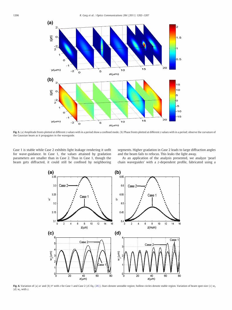
Fig. 5. (a) Amplitude fronts plotted at different z values with in a period show a confinedmode. (b) Phase fronts plotted at different z values with in a period; observe the curvature ofthe Gaussian beam as it propagates in the waveguide.
1206 R. Garg et al. / Optics Communications 284 (2011) 1202–1207
Case 1 is stable while Case 2 exhibits light leakage rendering it unfitfor wave-guidance. In Case 1, the values attained by gradationparameters are smaller than in Case 2. Thus in Case 1, though thebeam gets diffracted, it could still be confined by neighboring
Fig. 6. Variation of (a) α′ and (b) θ′ with z for Case 1 and Case 2 (cf. Eq. (26)). Stars denote(d) wy with z.
segments. Higher gradation in Case 2 leads to large diffraction anglesand the beam fails to refocus. This leaks the light away.
As an application of the analysis presented, we analyze ‘pearlchain waveguides’ with a z-dependent profile, fabricated using a
unstable region; hollow circles denote stable region. Variation of beam spot-size (c) wx

Fig. 7. The figure shows the dependence of the stability of the segmented waveguide on the duty cycle. The waveguide is stable for duty cycles of 0.6 and 0.9 and unstable for smalland large duty cycles. Variation of beam spot-size (a)wx (b)wy with z for stable (γ=0.6) and unstable (γ=0.4, 0.5) duty cycles. Variation of beam spot-size (c)wx (d)wy with z forstable (γ=0.9) and unstable (γ=0.95, 0.99) duty cycles.
1207R. Garg et al. / Optics Communications 284 (2011) 1202–1207
femtosecond laser inscription technique [21]. In order to model suchwaveguides, we have chosen the following values of variousparameters [21]:
n1 = 1:5239; n2 = 1:5139;λ0 = 0:67μm; α′ = 0:8625; θ′ = 0:225;Λ = 7:5μm; d0 = d= 2; N = 100; C1 = 2:5;C2 = 8:
Fig. 7 shows the variation of Gaussian spot-sizes with z for differentduty cycles; it shows that light guidancebecomes inefficient at very highand low duty cycles. Figs. 7(a) and (b) depicts that for γ=0.6, the beamremains confined where as for γ=0.4 and 0.5, it diverges in x- and y-directions on propagation. Fig. 7(c) and (d) leads to similar observationsfor higher values of duty cycles. Since the duty cycle depends on sampletranslation speed, our results agree with the general observation ofauthors [21] regarding guidance of such waveguides.
4. Conclusion
We have presented a method for analyzing buried segmentedwaveguide with parabolic index segments in which the gradingparameters and the axial index can be z-dependent. The analysisshould be useful for obtaining the propagation characteristics ofburied segmented channel waveguides fabricated using diffusiontechniques or femtosecond laser inscription techniques. The analysiscould be used to analyze periodic segmented waveguides with othertransverse dependence than infinitely extended parabolic profiles, interms of modal spot-sizes, stable regions of operation, and effectiveindex variation with period and duty cycle of segmentation. We showthat such segmented waveguides possess some novel behavior owingto the z-dependence. The analysis offers flexibility to change thegradation parameters and refractive index function along z to realizenew waveguide devices.
Acknowledgements
One of the authors (Ruchi Garg) is grateful for the Junior ResearchFellowship provided by the Council of Scientific and IndustrialResearch (CSIR), India. This work was partially supported by aresearch grant from the Office of Principal Scientific Advisor to theGovernment of India through a project titled “Fabrication andsubmicron tailoring of materials for photonics applications with ultrafastlasers”.
References
[1] J.D. Bierlein, D.B. Laubucher, J.B. Brown, C.J. Van der Poel, Appl. Phys. Lett. 56 (1990)1725.
[2] F. Laurell, J.B. Brown, J.D. Bierlein, Appl. Phys. Lett. 62 (1993) 1872.[3] P. Aschiéri, F. Fogli, P. Aumont, M.D. Micheli, G. Bellanca, P. Bassi, Opt. Commun.
235 (2004) 55.[4] W.P. Risk, S.D. Lau, Opt. Lett. 18 (1993) 272.[5] Z. Weissman, A. Hardy, J. Lightwave Technol. 11 (1993) 1831.[6] D. Castaldini, P. Bassi, P. Aschiéri, S. Tascu, M.D. Micheli, P. Baldi, Opt. Express
17 (2009) 17868.[7] Z. Weissman, Appl. Opt. 36 (1997) 1218.[8] M.A. Othman, K. Hassan, D.A. Khalil, Appl. Opt. 47 (2008) 5916.[9] K. Thyagarajan, C.W. Chien, R.V. Ramaswamy, H.S. Kim, H.S. Cheng, Opt. Lett.
19 (1994) 880.[10] K.R. Parameswaran, R.K. Route, J.R. Kurz, R.V. Roussev, M.M. Fejer, M. Fujimura,
Opt. Lett. 27 (2002) 179.[11] S. Nolte, M. Will, J. Burghoff, A. Tuennermann, Appl. Phys. A 77 (2003) 109.[12] K. Thyagarajan, V. Mahalakshmi, M.R. Shenoy, J. Indian Inst. Sci. 76 (1996) 175.[13] M.H. Chou, M.A. Arbore, M.M. Fejer, Opt. Lett. 21 (1996) 794.[14] P. Baldi, M.R. Shenoy, S. Nouh, M.P.D. Micheli, D.B. Ostrowsky, Opt. Commun.
104 (1994) 308.[15] L. Li, J.J. Burke, Opt. Lett. 17 (1992) 1195.[16] See, e.g., A. Gerrard, J.M. Burch, Introduction to Matrix Methods in Optics, Wiley,
London, 1975, p. 1168, Chap. 3.[17] A. Yariv, Optical Electronics, 3rd Ed., Holt, Rinehart and Winston, Orlando, 1985,
p. 358, Chap. 2.[18] K. Thyagarajan, V. Mahalakshmi, M.R. Shenoy, Opt. Lett. 19 (1994) 2113.[19] H. Kogelnik, T. Li, Appl. Opt. 5 (1966) 1550.[20] L.W. Casperson, J.L. Kirkwood, J. Lightwave Technol. 3 (1985) 256.[21] R. Graf, A. Fernandez, M. Dubov, H.J. Brueckner, B.N. Chichkov, A. Apolonski, Appl.
Phys. B 87 (2007) 21.