Embed Size (px)
Citation preview
Portland State University Portland State University
PDXScholar PDXScholar
Electrical and Computer Engineering Faculty Publications and Presentations Electrical and Computer Engineering
2-16-2017
Analysis of a Magnetically Geared Lead Screw Analysis of a Magnetically Geared Lead Screw
Mojtaba Bahrami Kouhshahi Portland State University
Jonathan Bird Portland State University
Follow this and additional works at: https://pdxscholar.library.pdx.edu/ece_fac
Part of the Electrical and Computer Engineering Commons
Let us know how access to this document benefits you.
Citation Details Citation Details Kouhshahi, Mojtaba Bahrami and Bird, Jonathan, "Analysis of a Magnetically Geared Lead Screw" (2017). Electrical and Computer Engineering Faculty Publications and Presentations. 421. https://pdxscholar.library.pdx.edu/ece_fac/421
This Post-Print is brought to you for free and open access. It has been accepted for inclusion in Electrical and Computer Engineering Faculty Publications and Presentations by an authorized administrator of PDXScholar. Please contact us if we can make this document more accessible: [email protected].
Analysis of a Magnetically Geared Lead Screw
Mojtaba Bahrami Kouhshahi, Jonathan Z. Bird Department of Electrical and Computer Engineering
Portland State University Portland, OR, USA [email protected]
Abstract— Linear magnetic gearboxes (LMG) and magnetic
lead screws (MLS) have been shown to be capable of operating at significantly higher volumetric force densities than traditional electromagnetic linear actuators (ELA). However in both such devices the linear translator must be made of magnet material and therefore if the stroke length of the translator is long the cost of the MLS and LMG will become prohibitively high. In this paper a magnetically geared lead screw (MGLS) is investigated and its performance capability is compared with the LMG and MLS. The advantage of the MGLS is that the translator does not contain magnets.
Keywords—magnetic gearbox; lead screw; linear actuator; finite element analysis
I. INTRODUCTION
Linear actuation is often achieved by utilizing either a hydraulic or mechanical gearing mechanism. By operating a hydraulic actuator at high pressure very high force densities can be sustained; for instance an excavator hydraulic piston can operate at a pressures of 38MPa [1]. Electromagnetic linear actuators have the advantage over hydraulic and mechanical mechanisms of being able to operate with higher efficiencies and are potentially more reliable [1]. However, the force density of a ELA is constrained by the current density and magnetic saturation. ELAs have been reported to have volumetric force densities in the range of 0.3kN/L with air-gap magnetic shear stress values in the range of 0.083MPa [2, 3]. Recently LMG and MLS have been proposed as a means of increasing the force densities of linear actuators. The LMG and MLS rely only on magnetic loading and therefore a higher magnetic air-gap shear stress can be sustained.
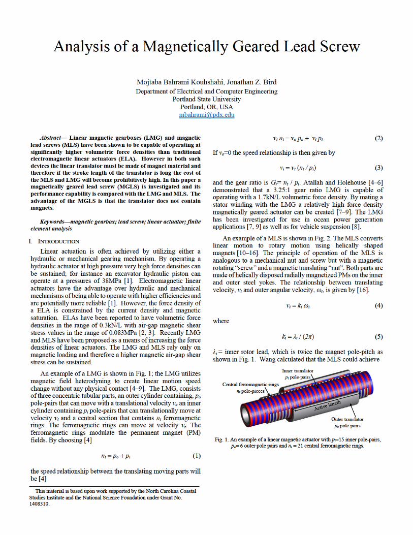
An example of a LMG is shown in Fig. 1; the LMG utilizes magnetic field heterodyning to create linear motion speed change without any physical contact [4–9]. The LMG, consists of three concentric tubular parts, an outer cylinder containing, po pole-pairs that can move with a translational velocity vo an inner cylinder containing pi pole-pairs that can translationally move at velocity vi and a central section that contains nt ferromagnetic rings. The ferromagnetic rings can move at velocity vt. The ferromagnetic rings modulate the permanent magnet (PM) fields. By choosing [4]
ntpopi
the speed relationship between the translating moving parts will be [4]
vt ntvo po vi pi
If vo=0 the speed relationship is then given by
vivt (nt / pi)
and the gear ratio is Gr= nt / pi. Atallah and Holehouse [4–6] demonstrated that a 3.25:1 gear ratio LMG is capable of operating with a 1.7kN/L volumetric force density. By mating a stator winding with the LMG a relatively high force density magnetically geared actuator can be created [7–9]. The LMG has been investigated for use in ocean power generation applications [7, 9] as well as for vehicle suspension [8].
An example of a MLS is shown in Fig. 2. The MLS converts linear motion to rotary motion using helically shaped magnets [10–16]. The principle of operation of the MLS is analogous to a mechanical nut and screw but with a magnetic rotating “screw” and a magnetic translating “nut”. Both parts are made of helically disposed radially magnetized PMs on the inner and outer steel yokes. The relationship between translating velocity, vi and outer angular velocity, ωi, is given by [16].
viki ωi
where
kiλi / (2π)
λi = inner rotor lead, which is twice the magnet pole-pitch as shown in Fig. 1. Wang calculated that the MLS could achieve
Fig. 1. An example of a linear magnetic actuator with pi=15 inner pole-pairs, po= 6 outer pole pairs and nt
Inner translator pi pole-pairs
Outer translator po pole-pairs
Central ferromagnetic rings nt pole-pieces
= 21 central ferromagnetic rings.
This material is based upon work supported by the North Carolina Coastal Studies Institute and the National Science Foundation under Grant No. 1408310.
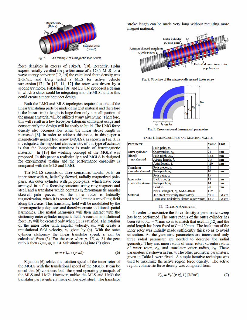
Fig. 2. An example of a magnetic lead screw
force densities in excess of 10kN/L [10]. Recently, Holm experimentally verified the performance of a 17kN MLS for a wave energy converter [12, 14] the calculated force density was 2.6kN/L and Berg tested a MLS for active vehicle suspension [17]. In [12, 14, 17] the rotor was driven by a secondary motor. Pakdelian [18] and Lu [16] proposed a design in which a stator could be integrating into the MLS, and so this could create a more compact design.
Both the LMG and MLS topologies require that one of the linear translating parts be made of magnet material and therefore if the linear stroke length is large then only a small portion of the magnet material will be utilized at any given time. Therefore, this will result in a low force-per-kilogram of magnet usage and consequently the design will be costly to build. The LMG force density also becomes low when the linear stroke length is increased [6]. In order to address this issue, in this paper a magnetically geared lead screw (MGLS), as shown in Fig. 3, is investigated; the important characteristic of this type of actuator is that the long-stroke translator is made of ferromagnetic material. In [19] the working concept of the MGLS was proposed. In this paper a realistically sized MGLS is designed for experimental testing and the performance capability is compared with the MLS and LMG.
The MGLS consists of three concentric tubular parts: an inner rotor with pi, helically skewed, radially magnetized pole-pairs. An outer cylinder with po pole-pairs, which have been arranged in a flux-focusing structure using ring magnets and steel, and a translator which contains nt ferromagnetic annular skewed pole pieces. As the inner rotor is helically magnetization, when it is rotated it will create a travelling field along the z-axis. This translating field will be modulated by the ferromagnetic pole pieces and therefore create additional spatial harmonics. The spatial harmonics will then interact with the stationary outer cylinder magnetic field. A constant translational force, Fz will be created only when (1) is satisfied. The rotation of the inner rotor with angular velocity, ωi, will create a translational field velocity, vi, given by (4). With the outer cylinder stationary the linear translator speed, vt can be calculated from (3). For the case when pi=15, nt=21 the gear ratio is then Gr=nt /pi = 1.4. Substituting (4) into (3) gives
ωivt (nt / (pi ki))
Equation (6) relates the rotation speed of the inner rotor of the MGLS with the translational speed of the MGLS. It can be noted that (6) combines both the speed operating principals of the MLS and LMG. However, unlike the MLS and LMG the translator part is entirely made of low-cost steel. The translator
stroke length can be made very long without requiring more magnet material.
Fig. 3. Structure of the magnetically geared linear screw
Fig. 4. Cross-sectional dimensional parameters
TABLE I. FIXED GEOMETRIC AND MATERIAL VALUES
Parameter Value Unit
Outer cylinder (fixed) - not skewed
Pole-pairs, po 6 - Outer radius, roo 71 mm Pole-pitch, 2wo 33.6 mm Airgap length, lg 0.5 mm Axial length, L 420 mm
Translator - annular skewed
Pole pieces, nt 21 - Pole-pitch, wt 10 mm
Inner rotor - helically skewed
Pole pairs, pi 15 - Back iron, lib 11 mm Pole-pitch, wi 14 mm Lead, λi 28 mm
Material NdFeB magnet, Br, NMX-40CH 1.25 T 416 steel resistivity (translator) 57.0 µΩ-cm 1018 steel resistivity (inner, outer rotors) 15.9 µΩ-cm
II. DESIGN ANALYSIS
In order to maximize the force density a parametric sweep has been performed. The outer radius of the outer cylinder has been set to roo = 71mm so as to match that used in [12] and the axial length has been fixed at L = 420mm. The back iron of the inner rotor was initially made sufficiently thick so as to avoid saturation. As the geometric parameters are interrelated only three radial parameter are needed to describe the radial geometry. They are: inner radius of inner rotor, rii, outer radius of inner rotor, rio, and translator outer radius, rto. These parameters are shown in Fig. 4. The other geometric parameters, given in Table I, were fixed. A simple iterative technique was used to maximize the active region force density. The active region volumetric force density was computed from:
VFdFt / (π r2oo L) [N/m3]
Magnetic screw (Helical)
Magnetic nut (Helical)
Helical skewed inner rotor pi pole-pairs
Outer cylinder po pole-pairs
Annular skewed translator nt pole-pieces
x
liblimlt
rib rii rio
roo
lo
rto
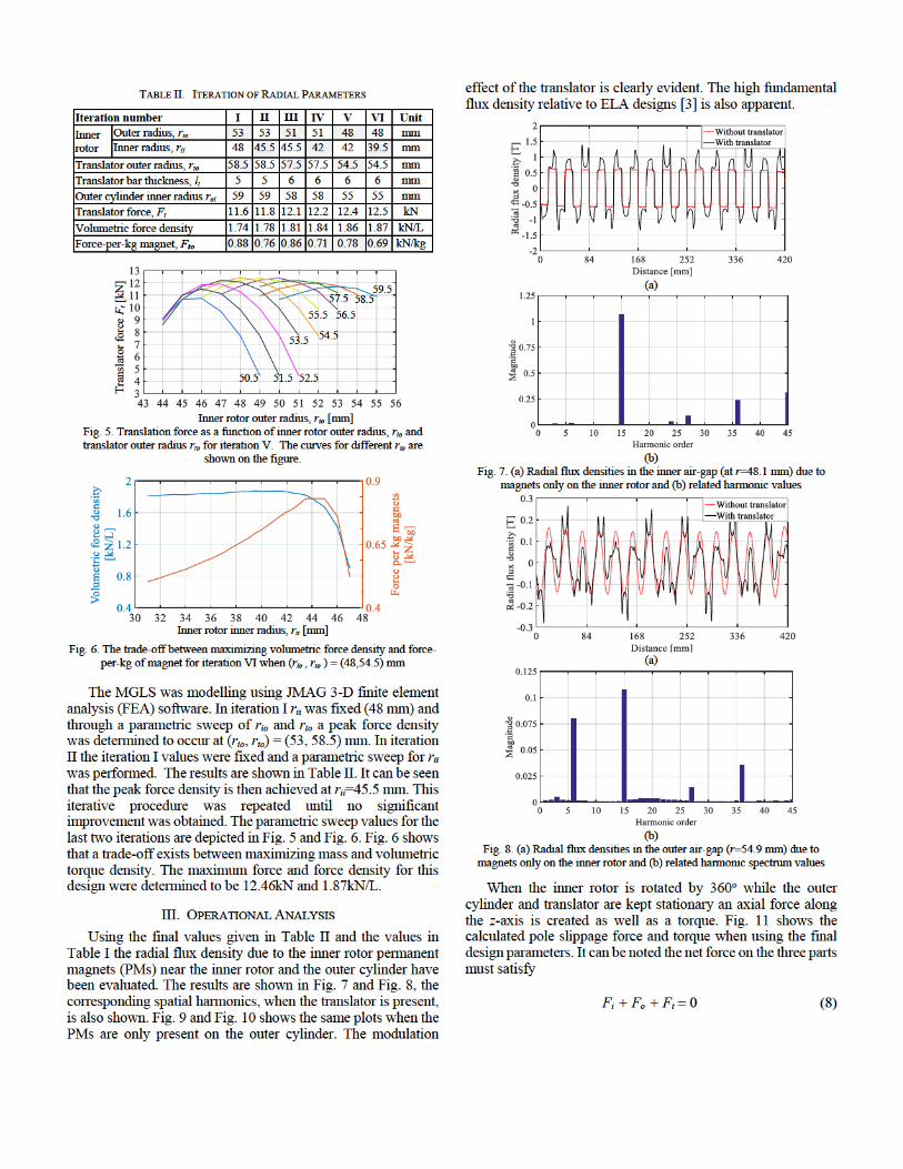
TABLE II. ITERATION OF RADIAL PARAMETERS
Iteration number I II III IV V VI Unit
Inner rotor
Outer radius, rio 53 53 51 51 48 48 mm
Inner radius, rii 48 45.5 45.5 42 42 39.5 mm
Translator outer radius, rto 58.5 58.5 57.5 57.5 54.5 54.5 mm
Translator bar thickness, lt 5 5 6 6 6 6 mm
Outer cylinder inner radius roi 59 59 58 58 55 55 mm
Translator force, Ft 11.6 11.8 12.1 12.2 12.4 12.5 kN
Volumetric force density 1.74 1.78 1.81 1.84 1.86 1.87 kN/L
Force-per-kg magnet, Fko 0.88 0.76 0.86 0.71 0.78 0.69 kN/kg
Translator force Ft [kN]
Inner rotor outer radius, rio [mm]
Fig. 5. Translation force as a function of inner rotor outer radius, rio and translator outer radius rto for iteration V. The curves for different rto are
shown on the figure.
Inner rotor inner radius, rii [mm]
Fig. 6. The trade-off between maximizing volumetric force density and force-per-kg of magnet for iteration VI when (rio , rto ) = (48,54.5) mm
The MGLS was modelling using JMAG 3-D finite element analysis (FEA) software. In iteration I rii was fixed (48 mm) and through a parametric sweep of rio and rto a peak force density was determined to occur at (rio, rto) = (53, 58.5) mm. In iteration II the iteration I values were fixed and a parametric sweep for rii was performed. The results are shown in Table II. It can be seen that the peak force density is then achieved at rii=45.5 mm. This iterative procedure was repeated until no significant improvement was obtained. The parametric sweep values for the last two iterations are depicted in Fig. 5 and Fig. 6. Fig. 6 shows that a trade-off exists between maximizing mass and volumetric torque density. The maximum force and force density for this design were determined to be 12.46kN and 1.87kN/L.
III. OPERATIONAL ANALYSIS
Using the final values given in Table II and the values in Table I the radial flux density due to the inner rotor permanent magnets (PMs) near the inner rotor and the outer cylinder have been evaluated. The results are shown in Fig. 7 and Fig. 8, the corresponding spatial harmonics, when the translator is present, is also shown. Fig. 9 and Fig. 10 shows the same plots when the PMs are only present on the outer cylinder. The modulation
effect of the translator is clearly evident. The high fundamental flux density relative to ELA designs [3] is also apparent.
(a)
(b)
Fig. 7. (a) Radial flux densities in the inner air-gap (at r=48.1 mm) due to magnets only on the inner rotor and (b) related harmonic values
(a)
(b)
Fig. 8. (a) Radial flux densities in the outer air-gap (r=54.9 mm) due to magnets only on the inner rotor and (b) related harmonic spectrum values
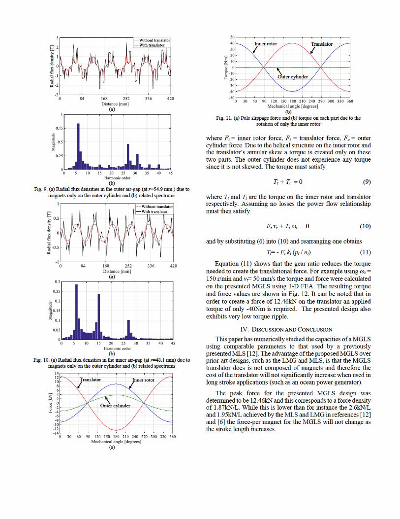
When the inner rotor is rotated by 360o while the outer cylinder and translator are kept stationary an axial force along the z-axis is created as well as a torque. Fig. 11 shows the calculated pole slippage force and torque when using the final design parameters. It can be noted the net force on the three parts must satisfy
Fi + Fo + Ft
59.5 58.5 57.5
56.5 55.5
54.5 53.5
52.5 51.5 50.5
(a)
(b)
Fig. 9. (a) Radial flux densities in the outer air-gap (at r=54.9 mm ) due to magnets only on the outer cylinder and (b) related spectrums
(a)
(b)
Fig. 10. (a) Radial flux densities in the inner air-gap (at r=48.1 mm) due to magnets only on the outer cylinder and (b) related spectrums
(a)
(b)
Fig. 11. (a) Pole slippage force and (b) torque on each part due to the rotation of only the inner rotor
where Fi = inner rotor force, Ft = translator force, Fo = outer cylinder force. Due to the helical structure on the inner rotor and the translator’s annular skew a torque is created only on these two parts. The outer cylinder does not experience any torque since it is not skewed. The torque must satisfy
Tt + Ti
where Ti and Tt are the torque on the inner rotor and translator respectively. Assuming no losses the power flow relationship must then satisfy
Ft vt + Ti ωi
and by substituting (6) into (10) and rearranging one obtains
Ti= - Ft ki (pi / nt) (11)
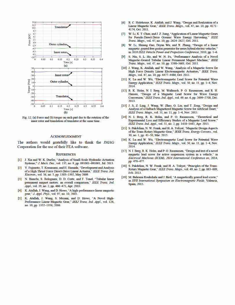
Equation (11) shows that the gear ratio reduces the torque needed to create the translational force. For example using ωi = 150 r/min and vt= 50 mm/s the torque and force were calculated on the presented MGLS using 3-D FEA. The resulting torque and force values are shown in Fig. 12. It can be noted that in order to create a force of 12.46kN on the translator an applied torque of only -40Nm is required. The presented design also exhibits very low torque ripple.
IV. DISCUSSION AND CONCLUSION
This paper has numerically studied the capacities of a MGLS using comparable parameters to that used by a previously presented MLS [12]. The advantage of the proposed MGLS over prior-art designs, such as the LMG and MLS, is that the MGLS translator does is not composed of magnets and therefore the cost of the translator will not significantly increase when used in long stroke applications (such as an ocean power generator).
The peak force for the presented MGLS design was determined to be 12.46kN and this corresponds to a force density of 1.87kN/L. While this is lower than for instance the 2.6kN/L and 1.95kN/L achieved by the MLS and LMG in references [12] and [6] the force-per magnet for the MGLS will not change as the stroke length increases.
Outer cylinder
Translator Inner rotor
Outer cylinder
Inner rotor Translator
(a)
(b)
Fig. 12. (a) Force and (b) torque on each part due to the rotation of the inner rotor and translation of translator at the same time.
ACKNOWLEDGMENT
The authors would gratefully like to thank the JMAG Corporation for the use of their FEA software.
REFERENCES
[1] J. Xia and W. K. Durfee, “Analysis of Small-Scale Hydraulic Actuation Systems,” J. Mech. Des., vol. 135, no. 9, pp. 091001–091001, Jul. 2013.
[2] Y. Fujimoto, T. Kominami, and H. Hamada, “Development and Analysis of a High Thrust Force Direct-Drive Linear Actuator,” IEEE Trans. Ind. Electron., vol. 56, no. 5, pp. 1383–1392, May 2009.
[3] N. Bianchi, S. Bolognani, D. D. Corte, and F. Tonel, “Tubular linear permanent magnet motors: an overall comparison,” IEEE Trans. Ind. Appl., vol. 39, no. 2, pp. 466–475, Apr. 2003.
[4] K. Atallah, J. Wang, and D. Howe, “A high-performance linear magnetic gear,” J. Appl. Phys., vol. 97, no. 10, 2005.
[5] K. Atallah, J. Wang, S. Mezani, and D. Howe, “A Novel High-Performance Linear Magnetic Gear,” IEEJ Trans. Ind. Appl., vol. 126, no. 10, pp. 1352–1356, 2006.
[6] R. C. Holehouse, K. Atallah, and J. Wang, “Design and Realization of a Linear Magnetic Gear,” IEEE Trans. Magn., vol. 47, no. 10, pp. 4171–4174, Oct. 2011.
[7] W. Li, K. T. Chau, and J. Z. Jiang, “Application of Linear Magnetic Gears for Pseudo-Direct-Drive Oceanic Wave Energy Harvesting,” IEEE Trans. Magn., vol. 47, no. 10, pp. 2624–2627, Oct. 2011.
[8] W. Li, Shuang Gao, Diyun Wu, and X. Zhang, “Design of a linear magnetic-geared free-piston generator for series hybrid electric vehicles,” in 2010 IEEE Vehicle Power and Propulsion Conference, 2010, pp. 1–6.
[9] S. Niu, S. L. Ho, and W. N. Fu, “Performance Analysis of a Novel Magnetic-Geared Tubular Linear Permanent Magnet Machine,” IEEE Trans. Magn., vol. 47, no. 10, pp. 3598–3601, Oct. 2011.
[10] J. Wang, K. Atallah, and W. Wang, “Analysis of a Magnetic Screw for High Force Density Linear Electromagnetic Actuators,” IEEE Trans. Magn., vol. 47, no. 10, pp. 4477–4480, Oct. 2011.
[11] K. Lu and W. Wu, “Electromagnetic Lead Screw for Potential Wave Energy Application,” IEEE Trans. Magn., vol. 50, no. 11, pp. 1–4, Nov. 2014.
[12] R. K. Holm, N. I. Berg, M. Walkusch, P. O. Rasmussen, and R. H. Hansen, “Design of a Magnetic Lead Screw for Wave Energy Conversion,” IEEE Trans. Ind. Appl., vol. 49, no. 6, pp. 2699–2708, Dec. 2013.
[13] J. Ji, Z. Ling, J. Wang, W. Zhao, G. Liu, and T. Zeng, “Design and Analysis of a Halbach Magnetized Magnetic Screw for Artificial Heart,” IEEE Trans. Magn., vol. 51, no. 11, pp. 1–4, Nov. 2015.
[14] N. I. Berg, R. K. Holm, and P. O. Rasmussen, “Theoretical and Experimental Loss and Efficiency Studies of a Magnetic Lead Screw,” IEEE Trans. Ind. Appl., vol. 51, no. 2, pp. 1438–1445, Apr. 2015.
[15] S. Pakdelian, N. W. Frank, and H. A. Toliyat, “Magnetic Design Aspects of the Trans-Rotary Magnetic Gear,” IEEE Trans. Energy Convers., vol. 30, no. 1, pp. 41–50, Mar. 2015.
[16] K. Lu and W. Wu, “Electromagnetic Lead Screw for Potential Wave Energy Application,” IEEE Trans. Magn., vol. 50, no. 11, pp. 1–4, Nov. 2014.
[17] N. I. Berg, R. K. Holm, and P. O. Rasmussen, “Design and test of a novel magnetic lead screw for active suspension system in a vehicle,” in Electrical Machines (ICEM), 2014 International Conference on, 2014, pp. 470–477.
[18] S. Pakdelian, N. W. Frank, and H. A. Toliyat, “Principles of the Trans-Rotary Magnetic Gear,” IEEE Trans. Magn., vol. 49, no. 2, pp. 883–889, Feb. 2013.
[19] M. Bahrami Kouhshahi and J. Bird, “A magnetically geared lead screw,” in XVII International Symposium on Electromagnetic Fields, Valencia, Spain, 2015.
Inner rotor
Outer cylinder
Translator
Outer cylinder
Inner rotor
Translator