Embed Size (px)
Citation preview

Gottfried Wilhelm Leibniz Universität Hannover
Fakultät für Elektrotechnik und Informatik Institut für Praktische Informatik Fachgebiet Software Engineering
Analysis, Implementation and Usage of Task Models for User Interface Generation
in ERP Systems
Bachelorarbeit
im Studiengang Informatik
von
Quang Lam Nguyen
Prüfer: Prof. Dr. Kurt Schneider Zweitprüfer: Prof. Dr.-Ing. Müller-Schloer Betreuer: Dipl.-Wirt.-Inform. Daniel Lübke
Hannover, 26. August 2007
1
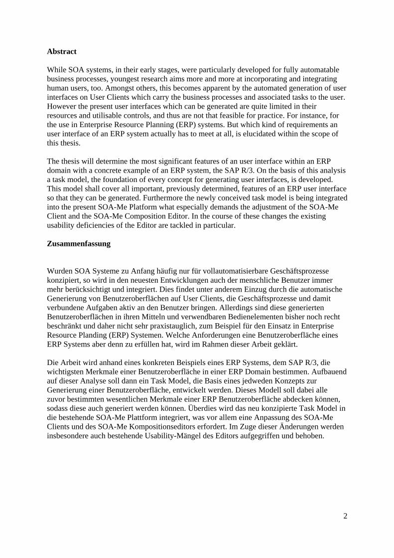
Abstract While SOA systems, in their early stages, were particularly developed for fully automatable business processes, youngest research aims more and more at incorporating and integrating human users, too. Amongst others, this becomes apparent by the automated generation of user interfaces on User Clients which carry the business processes and associated tasks to the user. However the present user interfaces which can be generated are quite limited in their resources and utilisable controls, and thus are not that feasible for practice. For instance, for the use in Enterprise Resource Planning (ERP) systems. But which kind of requirements an user interface of an ERP system actually has to meet at all, is elucidated within the scope of this thesis. The thesis will determine the most significant features of an user interface within an ERP domain with a concrete example of an ERP system, the SAP R/3. On the basis of this analysis a task model, the foundation of every concept for generating user interfaces, is developed. This model shall cover all important, previously determined, features of an ERP user interface so that they can be generated. Furthermore the newly conceived task model is being integrated into the present SOA-Me Platform what especially demands the adjustment of the SOA-Me Client and the SOA-Me Composition Editor. In the course of these changes the existing usability deficiencies of the Editor are tackled in particular. Zusammenfassung Wurden SOA Systeme zu Anfang häufig nur für vollautomatisierbare Geschäftsprozesse konzipiert, so wird in den neuesten Entwicklungen auch der menschliche Benutzer immer mehr berücksichtigt und integriert. Dies findet unter anderem Einzug durch die automatische Generierung von Benutzeroberflächen auf User Clients, die Geschäftsprozesse und damit verbundene Aufgaben aktiv an den Benutzer bringen. Allerdings sind diese generierten Benutzeroberflächen in ihren Mitteln und verwendbaren Bedienelementen bisher noch recht beschränkt und daher nicht sehr praxistauglich, zum Beispiel für den Einsatz in Enterprise Resource Planding (ERP) Systemen. Welche Anforderungen eine Benutzeroberfläche eines ERP Systems aber denn zu erfüllen hat, wird im Rahmen dieser Arbeit geklärt. Die Arbeit wird anhand eines konkreten Beispiels eines ERP Systems, dem SAP R/3, die wichtigsten Merkmale einer Benutzeroberfläche in einer ERP Domain bestimmen. Aufbauend auf dieser Analyse soll dann ein Task Model, die Basis eines jedweden Konzepts zur Generierung einer Benutzeroberfläche, entwickelt werden. Dieses Modell soll dabei alle zuvor bestimmten wesentlichen Merkmale einer ERP Benutzeroberfläche abdecken können, sodass diese auch generiert werden können. Überdies wird das neu konzipierte Task Model in die bestehende SOA-Me Plattform integriert, was vor allem eine Anpassung des SOA-Me Clients und des SOA-Me Kompositionseditors erfordert. Im Zuge dieser Änderungen werden insbesondere auch bestehende Usability-Mängel des Editors aufgegriffen und behoben.
2

Erklärung Hiermit versichere ich, dass ich die vorliegende Bachelorarbeit selbstständig und ohne fremde Hilfe verfasst und keine anderen als die in der Arbeit angegebenen Quellen und Hilfsmittel verwendet habe. _______________________________________________ Quang Lam Nguyen, Hannover, den 26.08.2007
3

Danksagung Ich danke Herrn Daniel Lübke für die vorbildliche und hervorragende Betreuung dieser Arbeit. Außerdem danke ich auch den Professoren Kurt Schneider und Jorge Marx Gómez, und Herrn Nico Brehm für die Unterstützung dieser Arbeit.
4

Inhaltsverzeichnis1 Introduction ............................................................................................................................. 7
1.1 Motivation ....................................................................................................................... 7 1.2 Problem Definition and Domain...................................................................................... 7 1.3 Structure .......................................................................................................................... 8
2 Foundations ........................................................................................................................... 10 2.1 Service-Oriented Architecture....................................................................................... 10 2.2 SOA-Me-Platform ......................................................................................................... 12 2.3 Task Model .................................................................................................................... 13
2.3.1 Overview................................................................................................................ 13 2.3.2 Relevant task models in the thesis ......................................................................... 15
2.4 SAP................................................................................................................................ 16 2.4.2 SAP R/3 and ERP Systems.................................................................................... 17
3 Requirements - Analysis of the User Interface of SAP R/3.................................................. 18 3.1 SAP GUI 4.6D.............................................................................................................. 18 3.2 Gathering the features of SAP GUI............................................................................... 21 3.3 Evaluation and Prioritisation of the features ................................................................. 21 3.4 Table of Features ........................................................................................................... 23 3.5 Evaluation of the existing task models .......................................................................... 25 3.6 Requirements for the new SOA-Me Platform ............................................................... 27
4 Redefinition of the task model and its UI model .................................................................. 28 4.1 Containers...................................................................................................................... 29 4.2 Description of containers in UI models in comparison ................................................. 30 4.3 Usability shortcoming of the old UI model ................................................................... 32 4.4 The new and the old UI model ...................................................................................... 33
4.4.1 The new UI model ................................................................................................. 33 4.4.2 The old UI model ................................................................................................... 34
4.5 Improvements of the new UI model .............................................................................. 34 4.5.1 Similarities ............................................................................................................. 34 4.5.2 Differences............................................................................................................. 35 4.5.3 Summary................................................................................................................ 36
5 Adapting the SOA-Me Platform to the new UI model.......................................................... 37 5.1 The Editor – a new UI Modelling Tool ......................................................................... 37
5.1.1 Old UI modelling concept...................................................................................... 37 5.1.2 Usability deficiencies............................................................................................. 38 5.1.3 New UI Modelling Tool ........................................................................................ 39
5.2 The Client – a new UI generation engine ...................................................................... 40 5.2.1 The old concept of the UI generation engine......................................................... 41 5.2.2 The new concept of the UI generation engine ....................................................... 43 5.2.3 In comparison ........................................................................................................ 44
5.2.3.1 Control-Selection section ............................................................................... 44 5.2.3.2 Programming-related enhancements.............................................................. 45 5.2.4 Format of the User Response ............................................................................ 45
5.3 The Server ..................................................................................................................... 45 6 Extension of the SOA-Me-Platform...................................................................................... 46
6.1 Basic components of a GUI, in general......................................................................... 47 6.1.1 Tables..................................................................................................................... 47
Significance................................................................................................................ 47
5

SAP GUI exemplar .................................................................................................... 47 SOA-Me exemplar ..................................................................................................... 48 The UI model– appendix B ........................................................................................ 48 Changes in SOA-Me .................................................................................................. 49 Outlook....................................................................................................................... 49
6.1.2 Child Windows ...................................................................................................... 50 Siginificance............................................................................................................... 50 SAP GUI exemplar .................................................................................................... 50 SOA-Me exemplar ..................................................................................................... 50 The UI model – appendix C ....................................................................................... 50 Changes in SOA-Me .................................................................................................. 50 Outlook....................................................................................................................... 52
6.2 Value helps .................................................................................................................... 52 6.2.1 Support Elements................................................................................................... 53 6.2.2 Matchcode.............................................................................................................. 54
Siginificance............................................................................................................... 54 SAP Gui exemplar...................................................................................................... 55 SOA-Me exemplar ..................................................................................................... 55 The UI model ............................................................................................................. 55 Client .......................................................................................................................... 56 Server ......................................................................................................................... 56 Editor.......................................................................................................................... 56
6.2.2 Autocomplete input fields...................................................................................... 56 6.3 Navigation and Access elements ................................................................................... 57
6.3.1 Easy Access ........................................................................................................... 57 Significance................................................................................................................ 57 SAP GUI exemplar .................................................................................................... 57 SOA-Me exemplar ..................................................................................................... 58 Client-Server interface ............................................................................................... 58 Changes in SOA-Me .................................................................................................. 59
6.3.2 Command field ...................................................................................................... 60 7 Conclusion and Outlook ................................................................................................... 61
Appendix .................................................................................................................................. 68 Appendix A: UI Descriptions for figures 4.2 and 4.3 ......................................................... 69 Appendix B: Schema for tables ........................................................................................... 70 Appendix C: Schema for the ui element.............................................................................. 71 Appendix D: Sample screen of the SOA-Me-Client ........................................................... 72
6

1 Introduction
1.1 Motivation The young concept of Service-Oriented Architectures (SOA) with its advantages like loosely coupled systems, distributed computing and ownership is popular as ever. In particular, this applies to Web Services which are starring accompanying technologies of SOA. The appliance of SOA paradigms promises [Lüe05]:
- flexible business processes, which are composed out of services - reduction of complexity - reuse of existing components - Enterprise Application Integration (EAI), which is the embedding of legacy systems in
new systems Although there are still dissension on what SOA actually means in terms of a definition, this new concept has already attracted many people.
Many adherents of SOA discover this new design principle as a feasible way to integrate business processes in enterprises in order to gain flexible and economical IT landscapes. While at the beginning mostly processes were integrated which could be fully automated by services, many recent approaches incorporate human interactions in SOA systems. That means that user tasks are integrated into business processes. In order to do this an interface must be provided through which the user can access various business processes and operate on them. This led to the development of several models for dynamic user interface generation.
However those efforts actually just demonstrates that mechanisms for user interaction and user interface generation in business SOA systems are implementable at all. This thesis makes a step forward by bringing the human user and the business as such to the fore but not the IT infrastructure beyond the SOA system.
In the scope of this thesis it is analysed what an user interface must be capable of to ensure effective and efficient human interaction within business processes.
1.2 Problem Definition and Domain A user should performs his task satisfyingly in two regards. On the one hand, his work should be satisfying with regard to the correctness of his task execution within the business process. On the other hand, the user self should experience a certain level of satisfaction while he performs the task. These to kinds of satisfaction can be decisively defined by the user interface that is used to execute the task.
If an user interface for a certain task is appropriate or not depends on
1. the data which is provided to the user on the user interface
2. by what means this data is presented to the user and made available for manipulation
While the first point is exclusively determined by the business logic, the other is strongly dependent on the capability of an user interface to implement certain GUI controls and other
7

structures. To specify the two points above for a definite task moreover we have to take the domain into account a task is embedded in. It is necessary to define such an application domain because, for example, a GUI of an image editing tool is very different from the GUI of an ERP system.
The goal of this thesis is it to make out the characteristics and capabilities of user interfaces settled in the domain of ERP systems. That means GUI controls and other GUI elements have to be identified which are necessary for the execution of ERP specific tasks. Hereby, the analysis of the appropriateness of certain user interfaces in respect to certain tasks will not be within the scope of this thesis. Having specified the ERP GUI specific elements a task model is to be designed to make these elements feasible in the SOA-Me Platform via the SOA-Me Client. This means the Client must be able to generate user interfaces which contains these special elements. To understand what a task model is and why it is the centre point of generating an user interface the underlying concept of Model-based User Interface Design (MB-UI) must be put on record. A crucial strength of MB-UI is the Programming in the Large concept that implies the definition of user interfaces on an abstract level. As a result of the use of MB-UI an extension of the capability of a user interface also implies an extension of the task model. As the task model is the basis of every generated user interface. Due to the MB-UI-Design approach it also becomes clear why the variety of possible user interfaces must be restricted to one single domain. If one tried to create a single task model for different application domains, the task model would become so complicated that applying MB-UI paradigms would be senseless. Especially the virtues of the Programming in the Large concept would be nullified. This is because the definition of abstract user interfaces would not be more efficient than an usual explicit definition of an user interface. In the course of the adaptation of the Client to the new task model, the Editor and the Server component of the SOA-Me-Platform has to be modified ,too. This is done to hold the functionality of the SOA-Me system. To be able to specify the characteristics of a GUI of an ERP system, a concrete and eligible exemplar of an ERP system must be analysed. In our case, the SAP R/3 system seemed to be more than appropriate. No surprise, as the enterprise business software market and the ERP system market, in particular, is undoubtedly dominated by SAP.
1.3 Structure The thesis is structured as follows. In chapter 1 the foundations on SOA, task models and SAP should give the reader a better understanding of the scope of this thesis. The subsequent chapter 2 addresses the analysis of the user interface of the SAP R/3 System and the existing task models. Thereafter the whole chapter 3 is dedicated to the new task model, more precisely its user interface model, and its improvements with respect to the old one. Also containers as crucial parts of a task model are discussed in this chapter.
8

As the technical effect of the new user interface model on the SOA-Me Platform is significant, chapter 4 presents the fundamental modifications in the Client and Editor. The chapter 5 goes into the other several modifications of the SOA-Me Platform and outlines how certain features of the user interface of the SAP R/3 system were implemented in the SOA-Me Platform.
The concluding chapter will again take up the questions of this thesis and presents the results of the thesis.
9

2 Foundations In this chapter, information is presented which supports the comprehensibility of this thesis. First, Service-Oriented Architectures are presented with a focus on the advantages of UI generation concepts in SOA systems. Thereupon the components of the SOA-Me Platform are explained. Subsequently, fundamentals of task models, especially those integrated in development methods based on Event-Driven Process Chains (EPC), are discussed. Furthermore, existing task models are regarded in this context, too. The last section gives a short overview of the SAP company and the SAP R/3 system. In particular, the significance of the R/3 system in the domain of ERP-Systems is pointed out.
2.1 Service-Oriented Architecture SOA is an architecture pattern which can be applied to build and maintain highly flexible IT infrastructures for executing business processes. The concept determines the provision of functional units, called services, which conduct atomic process steps. Hence a business process is specified as a composition of services (Service Composition). It can be executed by calling these services in respect of a certain business logic. Though there is still no secure definition of what Service-Oriented Architecture actually is, the following points have emerged to be integral features of a SOA.
• services are the basic components of a SOA and are loosely coupled with each other • service providers make their services available and the latter are retrieved by service
consumers • services interact with their environment by using Open Standards (e.g. SOAP – a
communication protocol, WSDL - Web Service Description Language, UDDI – a service registry) and thus hide their complexity
• using a service is not restrained by the context and business logic it is executed in. The provision and usage of a service are thought to relate to each other as follows. A Service Provider registers his Service at a Service Registry or Repository (e.g. UDDI). This happens by depositing the Service Description (see WSDL) of the Service. Then, Service Consumers may obtain the addresses and Service Description of their desired Services and call these for their own purposes and business processes. The most established technology to implement services of a SOA are software systems called Web Services. Many enterprises embark on SOA as a strategy as they aim at flexible enterprise IT landscapes and reduced costs. The most significant advantages of a SOA are:
– high flexibility due to the composition of services – cost-cutting due to the reuse of existing components – reduction of complexity due to the breaking down of monolithic IT structures – effective and efficient use of heterogeneous IT landscapes
The first point is perhaps the most prominent one about a SOA. However the degree of the flexibility depends on the types of services which are actually used for the execution of a
10

business process. As long as only business logic components like Web Services occur in the Service Composition the point above is absolutely true. But as soon as user tasks as a second type of service are integrated into the composition, too, the flexibility of a SOA is determined by a further aspect. And this aspect concerns the generation of user interfaces. To change a business process often also implies the change of the data flow within it. That could mean for instance that certain data is required at other stages of a process or that new data is inducted. Hence user tasks must be modified, too. While changing a business logic component may just mean to replace a Web Service by another, changing user tasks requires a modification of an user interface. And this task must be as easy and uncomplicated to conduct as the modifying of Service Compositions, to preserve the flexibility of a SOA in regard to changing business processes. Consequently, user interfaces for user tasks must be highly adaptable to prevent a kind of bottleneck in the process of changing a business process. And this is why concepts of Model-based User Interface Design (MB-UID) are used to enable the dynamic generation of user interfaces. Thus the generation of user interfaces in a SOA that integrates user tasks as services is not a mere supplementary feature but an essential one that ensures the flexibility of a SOA.
11
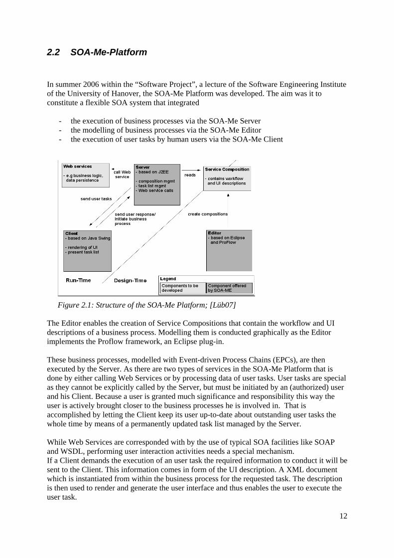
2.2 SOA-Me-Platform In summer 2006 within the “Software Project”, a lecture of the Software Engineering Institute of the University of Hanover, the SOA-Me Platform was developed. The aim was it to constitute a flexible SOA system that integrated
- the execution of business processes via the SOA-Me Server - the modelling of business processes via the SOA-Me Editor - the execution of user tasks by human users via the SOA-Me Client
Figure 2.1: Structure of the SOA-Me Platform; [Lüb07] The Editor enables the creation of Service Compositions that contain the workflow and UI descriptions of a business process. Modelling them is conducted graphically as the Editor implements the Proflow framework, an Eclipse plug-in. These business processes, modelled with Event-driven Process Chains (EPCs), are then executed by the Server. As there are two types of services in the SOA-Me Platform that is done by either calling Web Services or by processing data of user tasks. User tasks are special as they cannot be explicitly called by the Server, but must be initiated by an (authorized) user and his Client. Because a user is granted much significance and responsibility this way the user is actively brought closer to the business processes he is involved in. That is accomplished by letting the Client keep its user up-to-date about outstanding user tasks the whole time by means of a permanently updated task list managed by the Server. While Web Services are corresponded with by the use of typical SOA facilities like SOAP and WSDL, performing user interaction activities needs a special mechanism. If a Client demands the execution of an user task the required information to conduct it will be sent to the Client. This information comes in form of the UI description. A XML document which is instantiated from within the business process for the requested task. The description is then used to render and generate the user interface and thus enables the user to execute the user task.
12

As soon as a user commits his task a user response document is sent to the Server. The relevant data it contains is then extracted there and inducted into the business process. By doing so the user task in the business process is finished, so that the Server can continue with the execution of the process and invoke the next service. The SOA-Me Platform is exceptional in many ways for it defines human users as integral parts of business processes. This outstanding role of the human user is met by several features provided by the Client. For instance, the process list in the Client gives information on the processes a user is allowed to start. The task list was already mentioned above. On one side, the task list is a helpful element for the user and on the other side, it is purely necessary for the business process self. This is because a process might be simply delayed if a certain user task is not performed by a certain user ,because the respective person does not know about it. But the by far most important feature of the Client is the generation of user interfaces. Without adequate user interfaces a business process in the SOA-Me Platform could not flow at all. Therefore in the SOA-Me Platform the paradigms of Model-based User Interfaces (MB-UI) are applied. A significant model in this context is the task model.
2.3 Task Model
2.3.1 Overview To begin with two definitions shall be given to clarify the terms ’task’ and ‘task model’. Definition 1 (Task) A task is an activity aimed at the achievement of a goal and performed by a user. [Lüe05] Definition 2 (Task Model) A task model is often comprehended as a description of an interactive task to be performed by the user of an application through the application’s user interface. Individual elements in a task model represent specific actions that the user may undertake. Information on subtask ordering as well as conditions on task execution is also included in the model. [LV03]. When discussing task models four critical concepts for a task-based design of user interfaces have to be examined [LV03]:
1. Goal and Task Hierarchies 2. Expression of temporal constraints between tasks by operators 3. Role specification 4. Appropriate objects and actions that are performed on them enabling detailed
modelling of presentation and dialogue of user interfaces, in other words, enabling the design of concrete user interfaces.
All task models referenced to in this thesis are unusual in respect to their approach for they all are used as integral parts of business processes modelled with EPCs.
13

Event-driven process chains once were introduced as a rather informal description for business process work flows [KNS92]. As the processes are visualized with diagrams and quite self-explanatory symbols EPCs are intuitively comprehensible. And this makes them attractive for many companies when modelling or analysing business processes.
Figure 2.2: EPC elements; [Lüe05]
The main elements of an EPC graph are events and functions that are chained to each other in an alternating order. Parallel and alternative execution within a process is made available by the use of various connectors and logical operators, such as AND, OR and XOR. Control flow transitions define the flow of a process and connect the elements.
Using EPCs for task modelling was first proposed by Lüecke [Lüe05]. As Lüecke stated, that brings, among other things, the advantage that EPCs are per default goal-oriented due to their transitional nature. Moreover, temporal relationships between tasks are already integrated by the sequential ordering of EPC elements. Furthermore, the hierarchical structure of EPCs allow the construction of structured tasks on business layer. Role specification is made possible by applying certain user- or group-elements in EPC. Data for the concrete modelling of presentation and dialogue of user interfaces is supplied by setting specifications for atomic and complex tasks which directly refer to GUI components. Integrating task models into business processes modelled with EPCs enables a logical decomposition of task models into two layers. On the one hand, there is the business layer, represented by the workflow of a process and the EPC-structure, which can assemble the concepts 1,2 and 3 [LV03] (s. preceding page) of a task model. On the other hand, the fourth concept, addressed above, is hold in the user interface layer, which is levelled below the business layer. Such a decomposition of task models into two layers makes possible a clear separation of the actual presentation of a task on the GUI and the other crucial concepts 1-3 of a task model. This separation is pointed out in this thesis to help the reader understand that the requirements for new features for a generated user interface only influence definite parts of a task model. Neither the goal-concept nor the task hierarchies-concept of a task model are affected by changes which solely concern the user interface of the Client. And that is why this thesis actually only focuses and discusses task models in respect to their concepts on the user interface layer, more precisely their user interface models (UIM). An UIM is used to describe the presentation of tasks composed on an user interface via an abstract user interface or the UI description. These models enable the specification of the GUI objects and the actions that are performed on them. The objects and actions in turn are determined in the business layer of a task model and hence form the conjunction points between the UI layer and the business layer. Such a determination process shall be outlined briefly with an example: Supposed there is a certain Web Service function in a business process that requires as input the “name” of a user. This data though must be entered by
14

someone and hence a respective user task is needed with the output “name”. On the basis of that the action “EDIT ‘name’ ” is derived. Furthermore the corresponding object is specified with the type “String” to give the variable “name” an appropriate data type. Together the action and the object represent an (user interface) task. They would then be integrated into an UI description and finally be generated as a simple textfield, for example. An user interface, in general, is a composition of atomic and complex (user interface) tasks. Complex tasks are often assigned to GUI containers (e.g. tabs) for they can contain other tasks and are tasks inherently. Their counterparts are atomic tasks which, as their type name imply, cannot contain other subcomponents. Atomic tasks are often attached to simple elements like textfield or radiobuttons. The connection between a task and the presentation of it on an user interface is enacted by a mapping function that assigns to each task an appropriate GUI element.
2.3.2 Relevant task models in the thesis There are three task models which are of relevance for this work. In 2005, Lüecke developed within the scope of his Msc thesis a task model which composed user and Web Service activities. Although his model was not yet applicable for generating complex tasks on an user interface he introduced the four types of atomic tasks shown in table 2.1 on the next page. Lüecke’s task model, including the declared four types of atomic tasks, was taken up in the Msc thesis of Gutbier [Gut07] and particularly in the development of the SOA-Me Platform. Gutbier created a new lightweight task model which was able to integrate complex tasks and thus overcame the shortcoming of Lüecke’s model. Lightweight, in this context, means that Gutbier’s task model is both simple and sufficient. Simple as it is intuitively to use and sufficient for it provides a good basis for describing user interfaces in ERP specific domains. At the same time the SOA-Me project was set off which again produced another task model. But this one rather turned out badly for it was a complicated attempt of extending Lüecke’s model with complex tasks. However the remarkable point about the SOA-Me Platform in respect to task models was the implementation and the usage of the extended EPCs proposed by Lüecke in the Editor. His EPML [MN05] extensions concerned the integration of user interactions and are reflected in new EPC elements like an UI Container or elements for the four atomic task types.
15

Name Description Control The user explicitly invokes some action. This is used to
model navigational decisions. Properties: • possible actions [at least two]
Display The user has to do something by himself, e.g. planning, comparing, etc. Properties: • an information object the user needs for this purpose [optional]
Edit The user edits some information object from the data model. Properties: • information object to be edited
Select The user selects data from a collection of possible choices. Properties: • information object holding a list of other objects • information object as the target of the selection • multiple or single choice
Table 2.1: Four atomic types of tasks; [Lüe05]
2.4 SAP
2.4.1 The Company SAP AG The SAP AG is headquartered in Walldorf/Baden and was founded in 1972 by five former IBM engineers. With approximately 39,300 employees in more than 50 countries and a worldwide total turnover of € 9,4 billion [SAP06] it is one of the world's largest software company and the world-wide leading supplier of business software solutions [RRZN06]. The acronym SAP stands for “Systeme, Anwendungen und Produkte in der Datenverarbeitung“ (“Systems, Applications and Products in Data Processing”). “SAP's products focus on Enterprise Resource Planning (ERP), which it helped to pioneer. The company's main product is SAP ERP. The name of its predecessor, SAP R/3 gives a clue to its functionality: the 'R' stands for real-time data processing and the number 3 relates to its programme generation.” [Wik07a] SAP officials say there are over 100,600 SAP installations serving more than 41,200 companies in more than 25 industries in more than 120 countries. [SAP07]
16

2.4.2 SAP R/3 and ERP Systems
ERP systems attempt to unify all business processes and all data of an organization in a single system. That is often done by integrating various system modules which, for example, correspond to different departments in an enterprise. Additionally, a common database is used so that information can be easily shared and processed among the departments. These qualities of an ERP System are a direct response to the lack of enterprise software systems of the pre-ERP era. “Prior to the concept of ERP systems, departments within an organization (for example, the Human Resources (HR) department, the Payroll (PR) department, and the Financials department) would have their own computer systems” [Wik07b]. This often caused data synchronization conflicts and other problems.
The development of ERP systems has been considerably marked by SAP. According to Gartner Dataquest [Bai06] SAP holds the by far largest share in the market of ERP Systems with 28,7%. Oracle as the second largest vendor follows with 10,2%. Furthermore, taking into account the long experience of SAP with ERP Systems and the fact that Oracle's market share is particularly to be credited to the acquisition of PeopleSoft Corp.[Bru06], a former significant supplier of enterprise software, it is completely justified to consider SAP R/3 to be a representative of ERP Systems.
SAP R/3 is arranged into several functional modules which cover the typical functions of an organization. The most widely used modules are Financials and Controlling (FICO), Human Resources (HR), Materials Management (MM), Sales & Distribution (SD), and Production Planning (PP) [Wik07c]. The following features characterize SAP R/3 [RRZN06]: – Internationality
SAP R/3 can be used internationally due to its various language versions and its country-specific adaptability.
– Integration The data storage policy of SAP R/3 that uses a single, world-wide accessible database enables all users fast and optimal data access.
– Functionality Extending functionality by developing additional software modules
– Availability for a broad range of industries due to Customizing SAP R/3 is a business standard software and can be used in any industrial sector. On the one hand the system provides a range of business processes which are needed in every industry, on the other hand enterprise specific features are made feasible by the customizing.
– Scalability R/3 can be used in small architectures (e.g. 20 workstations) as well as in big architectures (e.g. 1.000 workstations) because it is adaptable and steplessly extendible
– Client/Server concept of SAP R/3 The R/3 system is a decentralized computer architecture. That means data acquisition, -processing and -storage are conducted on several different servers and not just on a single one.
17
3 Requirements - Analysis of the User Interface of SAP R/3 Before a new task model for an enhanced user interface on the Client and the extension of the SOA-Me Platform can be worked out at all, the qualities of such a novel user interface has to be set. At the beginning a concrete example of a user interface in the domain of ERP systems must be analysed. Then the relevant requirements are drawn out of that in order to define the capabilities of a task model that is to be used in an ERP specific domain. In this chapter this work process is explained step by step. It is shown by what criteria GUI elements were identified and graded to state the significant features of an ERP user interface. In our case the SAP R/3 system is drawn on as the basis of the analysis because this software is often used in industry.
3.1 SAP GUI 4.6D The graphical user interface of the SAP R/3 system is called SAP GUI. It represents the presentation layer of the Three-Tier Architecture of the system. Over the past years the SAP GUI developed from a simple user interface based on terminal screens to an impressive appearance that supports the users with many features. With each new release the interface was enriched by new qualities. The latest version 4.6D apart from “mySAP.com Workplace“ represents a further significant step of development. This is because the new SAP GUI dissociates from the Windows Look & Feel, which it had for a long time, and adopts a new unique GUI profile. [Wal04] The pictures on the following two pages shall give the reader an impression of the user interface. First the main components of a SAP R/3 window are depicted. Then some of the characteristic elements of the work area of R/3 are presented.
18
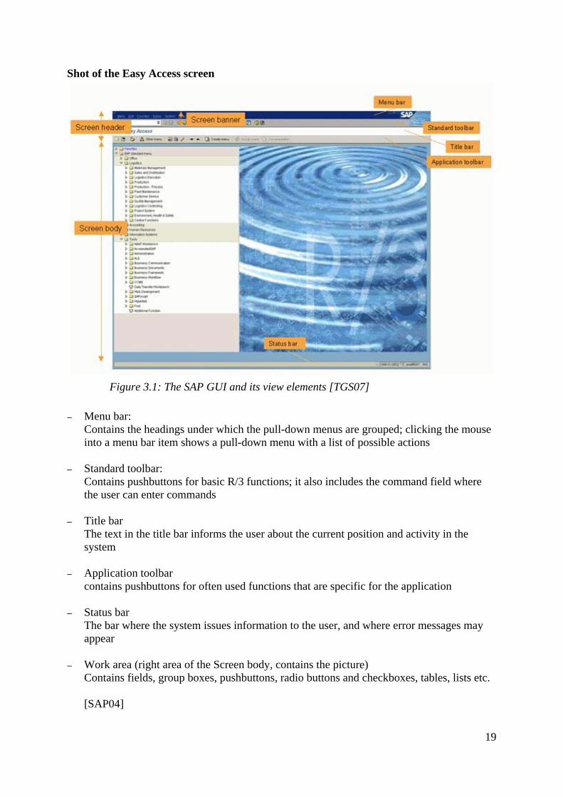
Shot of the Easy Access screen
Figure 3.1: The SAP GUI and its view elements [TGS07]
– Menu bar: Contains the headings under which the pull-down menus are grouped; clicking the mouse into a menu bar item shows a pull-down menu with a list of possible actions
– Standard toolbar: Contains pushbuttons for basic R/3 functions; it also includes the command field where the user can enter commands
– Title bar The text in the title bar informs the user about the current position and activity in the system
– Application toolbar contains pushbuttons for often used functions that are specific for the application
– Status bar The bar where the system issues information to the user, and where error messages may appear
– Work area (right area of the Screen body, contains the picture) Contains fields, group boxes, pushbuttons, radio buttons and checkboxes, tables, lists etc. [SAP04]
19

Shot of a typical SAP GUI screen
Figure 3.2: a typical SAP GUI screen with some of the characteristic elements
20
3.2 Gathering the features of SAP GUI
In the following the amount of all features is to be conceived as the entirety of all GUI elements and functions of the SAP GUI. That means that the command field is accounted for just as input fields, possible entries pushbuttons, the standard tool bar or navigation functions.
To ensure the credibility of the gathering case studies [WSV05a][WSV05b] from the industry were used. Their themes were “Cost Centre Accounting” and “Product Planning”. Due to their representative character of the day-to-day work of a “normal“ SAP R/3 user they provided an appropriate view on the user interface features which would be of relevance for an ERP system. Thus analysing the user interface of SAP R/3 was not just a mere sportive clicking through the SAP GUI without any concept.
While the case studies were conducted the features were collected in the form of screenshots and supplementary notes. These screenshots and notes were made whenever important features of the SAP GUI occurred. Simple aspects were regarded to determine if a feature was to be considered significant or not. The more often a feature was met and was used, the more likely it was to be an essential and useful element of the SAP GUI. Another question was to which extent a feature seemed to be supportive, especially when editing input fields because these element were encountered really often. Many rather inconspicuous features such as possible entries pushbuttons or tiny details like the short descriptions were recorded. On the other hand though basic and common features like textfields or check boxes as such were not noted down for they were simply familiar. Miscellaneous literature about SAP R/3 basics [RRZN06] or SAP style guides [SAP04] only had subsidiary character when gathering the features. The reason was that they, unlike the case studies, only provide few information about how often certain features are utilized by SAP R/3 users in practice. At this stage, this kind of literature was used to inform about the structure of the SAP GUI, in the first place.
3.3 Evaluation and Prioritisation of the features After having collected the sort of raw data the features were divided into three categories according to their importance. This step was necessary for it was clear that four months would be too short to implement all these features in the SOA-Me Platform. Four criteria were set up to determine the significance of the features and to accomplish the categorisation. But before they are explained it should be pointed out that first work on evaluation and sorting was already done before the features were gathered at all. The SAP GUI provides an abundance of features. The simple fact that there are more than 90 different functions and more than 20 elements, most of which even have accessory features, [SAP02] depicts that the entirety of the SAP GUI is hardly to be captured. From the very first it was apparent that the pool of gathered features would be only a subset of all existing in the SAP GUI. In addition to that the conduction of the case studies would do a further screening. That is due to their very nature to just present a brief overview of the most common and characteristic facilities of a programme. Although all this screening in advance does implicate
21

that the number of the collected features is not complete we can assume that they have a certain minimum of relevance for an ERP system. Finally, the four criteria below were used to set the final grade of significance for each feature and hence, constitute the last screening step. Frequency of occurrence The more often a feature occurred or was used in the case studies the higher ranked it was. This consideration resulted from the assumption that the more often a feature is encountered in the case studies the more useful, essential and typical it is for the R/3 system and ERP systems in general. Below the table 3.1 gives an overview of the number of occurrences of a few SAP GUI components (s. figure 3.2). The table is far from being complete but it gives a good impression of the look of the user interfaces occurring in the Sap R/3 system.
Fields and accessory elements Containers
Tables Tabs Group boxes Input/Output fields
Possible entries pushbuttons
Autocomplete functions or input
fields
24 8 79302 15 21
Table 3.1: Number of occurrences of few components of the SAP GUI
The census was conducted with about 35 screenshots of different user interfaces. What is noticeable is that fields, especially input fields, are definitely the predominant components of an ERP user interface. And that is also why possible entries pushbuttons or autocomplete functions must be assigned to a high priority for they support the work with input fields. This in turn means that tables must also be ranked high for they very often occur in context with the value helps invoked by the possible entries pushbuttons. Required fields are fields which have to be filled out to perform a task. Furthermore we see that containers are important features, too. Almost every user interface is structured by at least two group boxes. And although only eight tabs were counted these containers are perhaps even more significant than group boxes because they can provide additional room for other components. Functional and non-functional aspects Sometimes this criteria was difficult to use for it is hard to decide whether a feature is rather functional or non-functional. Especially when examining GUI elements, as every element provides a certain usability factor by implementing a certain functionality. A vivid example are value helps for input fields (e.g. autocomplete functions) which aid users to find the correct keys to enter. These supplementary elements are actually not necessary to perform a task because a user may get the correct values by other means, too. But in this case these value helps occurred and were used so many times (see criteria 1), that there was no other option than to rank them high. But in case of doubt often non-functional features were prioritised low as, in fact, the theme of this thesis sets it that way. One of the goals of this work is it to identify the basic and essential features of an ERP user interface which are required to conduct tasks in this domain.
22

With regard to that non-functional and usability features can only be adhered to conditionally. This is because usability factors may support the user significantly but are actually dispensable. Redundancy Wherever a range of several features provided alternative ways to access a certain functionality the option emerged to just rank high one of them. A good example are the file choosers in the SAP GUI, mainly operating on .txt-files, and the common Copy-Paste function in applications. Both features enable the loading and the saving of .txt-files, albeit under more circuitous means in the case of Copy & Paste. The crucial factor for deciding which feature to award importance and which features to 'drop' often was the fourth criteria – Complexity of Implementation. Complexity of Implementation The more difficult a feature seemed to be integrable in the SOA-Me Platform the more likely it was ranked low. In conjunction with the third criteria by this way the cost-benefit-analysis is reflected that the features were subjected to. To continue with the example with the file chooser and Copy Paste function, in this case the idea of the file chooser was dismissed. The technical operating expense for the integration of this element would have just been too disproportional to the benefit implicated by them. The significance of every feature was determined in consideration of all four criteria. This evaluation and prioritisation step established a table with nearly 25 features (Anhang ...).This table forms in combination with the screenshots and supplementary notes a database that lays the groundwork for all further works in this thesis. Next, a few representative rows of the table are presented to outline the structure, the function and the significance of it.
3.4 Table of Features The table works as a kind of roadmap and draft in this thesis. This is because it depicts which features are to be tackled in which order and provides first basic design decisions and draft proposals. The most important features are located in the upper half of the table and the least important in the lower one. Each feature is granted a row and the columns give information on
- the relevance and the possible SOA-Me instantiation of a feature and its impacts on
– the task model – the UI generation engine and other components of the SOA-Me system
However often some cells of the less significant features were left empty because their implementation in the SOA-Me system was excluded a priori right after having analysed the SAP GUI.
23

To provide a brief overview of the range of features represented in the table below three examples are depicted. Whilst the container- and Easy Access-feature belong to the most significant features, the third one is a representative of the lower ranked features. Containers
Table 3.2: Row concerning Containers from the Table of Features
Containers are mentioned at first place here as they are the most significant features of a user interface, apart from other basic components of a GUI like input fields. On the one hand, they make possible the structuring of user interface tasks. On the other hand, they, moreover, enable the specification of complex tasks (s. Section 4.1) in context with the Programming in the Large concept. However these great gains entail fundamental changes in the SOA-Me Platform. In the consequence, a new task model, a new UI generation engine and new means for modelling user interfaces in the Editor must be developed presumably. Easy Access - Grouping of processes by means of a tree
Table 3.3: Row concerning Easy Access from the Table of Features
24

In contrast to containers which affect almost each component of the SOA-Me Platform this feature only takes effect on the Process list of the Client. To group applications and processes of an enterprise is very important for there are plenty of them which has to be presented in a suitable way to the user. That this feature was ranked high also indicates one more time that the redesign of the GUI of the Client in this thesis aims at the GUI of a complex ERP system. As it would not make much sense to set up a tree component for accessing processes if there were only few to conduct at all. A tree is chosen as the navigation structure because it provides the most eligible means to represent the hierarchical structure of an enterprise. User preferences and settings These features were referenced to at the beginning of each case study. Although they enable a user to set up his or her own individual (and comfortable) working environment, they were not assigned a high priority to. Due to that was that they miss out on functional aspects and do not form a basic component of an ERP system (s. Criteria 2).
3.5 Evaluation of the existing task models To understand which new requirements a novel task model, more precisely its UI model, would have to meet, the already available models were inspected. The question was, how many of the ascertained features could have been already implemented by them. Examining these existing task models led to the conclusion that only two out of nearly 25 features were applicable yet, that is to say, the generation of containers and date choosers. Containers in SAP GUI are for example tabs or group boxes with the latter being equivalent to panels, as to be seen in figure 3.3. The task model developed by Gutbier [Gut07] offered a scheme to describe containers like these as shown in figure 3.4, or containers with horizontally arranged subcomponents. The user interface in figure 3.4 exemplifies the capability of the underlying task model to describe such elements.
Figure 3.3: Containers on the SAP GUI
25

Figure 3.4: Containers on the GUI of Gutbier’s User Client [Gut07]
The second already existing feature was the availability of date choosers which could be already used in the SOA-Me Platform and the respective SOA-Me task model. Since the specification of periods is needed for various tasks in SAP R/3 these elements are required to provide a comfortable control to edit information on date. These results, that only two features were applicable yet, did not surprise for the existing task models originally did not aim for the description of user interfaces of ERP systems. Hence it is clear that a new task model had to be conceived which would cover at least the most significant features from the SAP GUI.
26

3.6 Requirements for the new SOA-Me Platform According to the database established in section 3.3 the features listed below were considered as the most significant ones of the SAP GUI. Derived from the analysis of the R/3 user interface they shall constitute the requirements for the new SOA-Me Platform. The seven features permit a classification into three groups Basic components of a GUI, in general
– Containers: Group boxes, Tabs, horizontal arranged elements
– Tables: Editable and non-editable tables
– Child Windows: Support of the context of tasks
Value helps
– Matchcode: Table based value help for input fields
– Autocomplete input field: Value help for input fields
Navigation and access elements
– Easy Access: Grouping of processes by means of a tree
– Command field: Fast access to processes via transaction codes.
Each feature to be implemented in the SOA-Me Platform has a different impact on the components of the present system including the current SOA-Me task model. To what extent each feature is of relevance for an ERP user interface, its presentation on the GUI and the changes in the SOA-Me system that come along with it will be presented in detail in the subsequent chapters 4, 5 and 6. The first requirement to be taken are the containers. As their integration into a task model, more precisely the UI model, result in big structural changes this requirement is addressed in the next chapter together with the concept development of the new SOA-Me task model.
27

4 Redefinition of the task model and its UI model This chapter begins with a somewhat longer recapitulation of task models and UI models (see chapter 2). It is important to understand that the requirements for the new SOA-Me Platform do not affect the present task model as a whole but only a subcomponent of it, the UI model.
Every user task in a business process on the SOA-Me Platform can be described via a task model. The latter is often comprehended as a description of an interactive task to be performed by the user of an application through the application’s user interface [LV03]. As Limbourg and Vanderdonckt states the crucial elements and concepts of a task model are:
1. Goal and task hierarchies 2. Temporal constraints between tasks 3. Role specification as an aspect of cooperative tasks 4. Appropriate objects and actions that are performed on them enabling detailed
modelling of presentation and dialogue of user interfaces, in other words, enabling the design of concrete user interfaces.
This thesis examines the capabilities and features of an user interface required in an ERP system but not the first three aspects above. Only the fourth concept is of interest within the scope of this thesis. So we can fully concentrate on the objects and actions of a task model which are of primary importance for the presentation of user interfaces. These two properties in turn are included in the UI models of the SOA-Me task model, Gutbier’s model [Gut07] and Lüecke’s one [Lüe05]. This is because all these task models are integrated in business processes modelled with EPCs or BPEL and thus enable a logical decomposition of the task models into two layers. On the one side there is the user interface layer that contains the UI model and covers point 4. On the other side there is the business layer that includes the aspects 1-3 and that is described via EPC or BPEL structures. As all stated requirements for the new SOA-Me Platform take direct and sometimes grave effects on the UI model and thus on the other SOA-Me components, too, this chapter is wholly dedicated to this submodel of the task model. The aim of this chapter is to make the reader comprehend that a complete redefinition of the old SOA-Me UI model was necessary mainly due to its complicated description scheme for containers. At first, containers and their significance for user interfaces is elucidated. Then the big influence of the description scheme for containers on the structure of UI models is explained by comparing a good and a bad approach. Thereupon, the weak points of the present SOA-Me UI model are depicted, with special regard to usability aspects. This will then lead to the new SOA-Me UI model and its enhancements. The latter will especially include improvements of the integration of containers and hence the first requirement for the new SOA-Me Platform will be checked off in this chapter, too. Finally, the modifications of the UI generation engine in the Client and the new UI Modelling tool in the Editor are shown that were forced by the totally new concept of the UI model.
28

4.1 Containers UI models are core elements of the task models which are integrated into the Service Compositions of the SOA-Me system and are used to define the abstract UI descriptions for the Client. One of the most interesting aspects of UI models hereby is the description of containers which are for instance tabs, panels, group boxes in SAP and other complex tasks. All these elements have in common that they can contain other elements..
In our case, both the structure of the old and the new SOA-Me UI model are strongly affected by the description scheme for containers. Hence, it is obvious to discuss the implementation of the first requirement for the new SOA-Me Platform “containers” in this chapter, too.
A user interface is a virtual set of atomic tasks like textfields or radio buttons which enable a person to manipulate data. These atomic tasks can be ordered and their relationships between each other can be emphasized by structuring the user interface by means of containers like panels or tabs. In this thesis the implementation of containers is assigned a high priority for two reasons. A. Appealing and Efficient Mapping
Containers support the context of user tasks by structuring atomic tasks in an efficient way. For instance it is possible to provide numerous of atomic tasks by means of space-saving tabs. As these kind of containers can keep more components than the space a tabs container holds actually offers.
B. Programming in the Large
By using containers complex user interface objects can be specified in the UI model. The whole purpose is it to enable the designer of a user interface to describe an abstract user interface by means of complex tasks consisting of multiple atomic one. The advantage is that the designer can specify the UI description without being bounded to specify each atomic task manually.
29

4.2 Description of containers in UI models in comparison Now, a good and a bad approach of describing containers in UI models are compared with a simple example. The latter approach will be given by the UI model that was used in the old SOA-Me system. The former is taken from the newly developed UI model, whose other aspects will be explained in detail in the other sections of chapter 4.
Figure 4.1: Simple example of an user interface to demonstrate the integration of containers in UI models
Figure 4.1 shows an actually absurd user interface but which is absolutely sufficient for grasping the problem. There is a big panel A which contains a textfield B and a subpanel C. Furthermore two radio buttons D and C are embedded in this panel. A and C are obviously containers of the type “panel”.
Figure 4.3: Example modelled on the new UI model
Figure 4.2: Example modelled on the old UI model
How this example of an user interface would be described in UI descriptions modelled on the old and the new SOA-Me UI model is shown in Figure 4.2 and Figure 4.3.
30

Both UI descriptions are depicted as XML trees (see appendix A for the code view) and are on the same level of abstraction. Only the most essential information about the nodes is shown to make the difference between the implementations of containers comprehensible. For further qualities of the UI models please have a look at chapter 6, or the appendix where detailed views on the UI models as a whole are given. The new UI model in figure 4.3 seems to be very intelligible as the hierarchy of the elements on the user interface is mapped to the according XML tree one-to-one. While those XML elements which represent the containers in Figure 4.1 are inner nodes of the tree, the leaves correspond to the atomic tasks on the user interface (e.g. radio buttons). Generating the user interface in Figure 4.1 on the basis of the UI description in figure 4.3 is straightforward as only simple parsing must be carried out. An entirely different approach is obviously used in the old UI model. In contrast to the new model the old one is not that comprehensible at first view. This is because it implements (GUI) containers by using the concept of virtual container elements. Virtual container elements, as the name implies, do not exist as “real” container XML elements like in the new model. They are processed and derived in the Client on the basis of the UI description. That is done by merging certain elements in the abstract user interface. This principle is explained by describing the generation process for the user interface in figure 4.1 in the following example. Example (see Figure 4.2): To create the virtual container element represented by the panel A in figure 4.1 the three nodes named A have to be merged to a single node A. Placing the textfield B is done by simply appending node B to node A as a new child. To embed the panel C into the panel A another merge has to be done to create a single node C which then can be added to node A. Further merges are not necessary in this example for node D and E are represented by radio buttons which are atomic tasks. Merging the nodes in the SOA-Me Client in conjunction with the old UI model is subject to many prerequisites. The most important one is that the merge of nodes has to be done in a top-down approach. For example, the nodes named A has to be merged before a single node C is processed. Would not that be the case the XML tree would turn into a cyclic graph at some point during the merge process and thus become invalid causing an interruption of the UI generation process. Using the old UI model to define containers is truly a lot more complicated. But still both models are capable of providing information about how to set containers on the user interface. So in this respect they are on a par in terms of containers. Saying that the old UI model is worse than the new one because the latter can implement tabs and the former only panels (see chapter 3) is not very argumentative, by the way. The reason is that tabs and panels are both representatives of containers. Specifying more certain types of containers in the old UI model just requires one single new XML attribute in the UI description and interspersing minimal changes in the source code of the Client and the Editor of the SOA-Me system. That means that the technical integration of containers cannot be the crucial reason for developing a new UI model. Surely, there would be still six requirements left (see chapter 2)
31
which yet has to be implemented in the old UI model. However, due to the easiness of integrating them into the UI model the structure of the model self would be only changed irreducibly, making the work for a complete new concept development unjustified. Yet a mere extension of the current SOA-Me UI model would not be sufficient as its present form and structure together with the facilities to use it cannot satisfyingly meet the demands of an ERP system.
4.3 Usability shortcoming of the old UI model
Despite the fact the old UI model was already capable of specifying containers and even though the implementation of the requirements 2 – 7 (see chapter 2) would have no large effect on the structure of the old model a new one had to be developed. Though not because of technical aspects but because of the too severe usability deficiencies of the old UI model. The most serious usability shortcoming is the use of the concept of virtual container elements.
As already illustrated with the figure 4.2 the UI description based on the old UI model is quite complicated even for a simple user interface like in figure 4.1. Whilst such difficult UI descriptions can be still accepted for simple user interfaces, it could not be acquiesced at all if the old UI model is used to specify complex user interfaces as they occur in an ERP system. This is because the modelling of the UI descriptions would become too difficult. This task of specifying a description for a certain user interface is conducted by the designer in the SOA-Me-Platform.
The intricate implementation of the old UI model would make the issue of designing a complex abstract user interface very hard for several reasons. The facilities to develop an UI description in the current SOA-Me system, more precisely in the Editor, have much room for improvement as practical experience with the present SOA-Me-Platform did show [Kön07] (see section 4.4). Furthermore, the strict integration of the UI description into the modelling of business processes in the Editor does not enable the designing of the UI Description outside of the Editor that might facilitate this task in some way.
But even if assumed that such a separate designing of the UI Description would be possible, for example by means of a simple text editor, there would be still the complicated UI model self providing an absolutely inappropriate concept for describing containers in large and complex ERP user interfaces.
Taking all this into account it becomes clear why the old UI model has to be replaced by a new one. Neither its concept for describing containers nor the utilities, namely the Editor, for using it provide adequate, comfortable and user-friendly surrounding conditions for developing UI descriptions for ERP user interfaces.
In the next three subsequent sections the first deficiency, the concept for specifying containers, is tackled. The new UI model is presented and is then, to emphasize its optimisations, compared to the old one.
32
4.4 The new and the old UI model
To begin with the new UI model is explained as the reader first should get an idea of how easy it can be to describe a user interface, before the more complicated concept of the old model is addressed. Each model has in common that it includes a layout and an action section to make possible the specification of an user interface. The former part of an UI model defines the composition of the atomic tasks and their presentations, and the latter section specifies the values assigned to the several GUI components (e.g. a default text of a textfield).
4.4.1 The new UI model
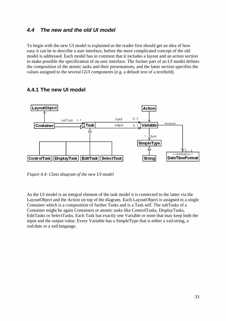
Figure 4.4: Class diagram of the new UI model
As the UI model is an integral element of the task model it is connected to the latter via the LayoutObject and the Action on top of the diagram. Each LayoutObject is assigned to a single Container which is a composition of further Tasks and is a Task self. The subTasks of a Container might be again Containers or atomic tasks like ControlTasks, DisplayTasks, EditTasks or SelectTasks. Each Task has exactly one Variable or none that may keep both the input and the output value. Every Variable has a SimpleType that is either a xsd:string, a xsd:date or a xsd:language.
33

4.4.2 The old UI model
Figure 4.5: Class diagram of the old UI model
As the UI model is an integral element of the task model it is connected to the latter via the LayoutObject and the Action on top of the diagram. Each LayoutObject is assigned to one or more Master that may be specified by Control, Display, Edit or Select. Each Master has got a single child, an InformationObject, which in turn contains an atomic task like ControlObj, DisplayObj, EditObj or SelectObj. Furthermore every InformationObject has exactly one Variable or none that may keep both the input and the output value. Every Variable has a SimpleType that is a xsd:string.
4.5 Improvements of the new UI model
The two models presented in the preceding sections are now compared to each other. Although the focus is on the enhancements of the new model, the similarities will be outlined as well.
4.5.1 Similarities As stated at the beginning of this chapter the issue of describing containers on a user interface and other GUI elements does not affect the task model as a whole but only its UI model. This breakdown is possible as the SOA-Me structures containing the task models are based on EPCs what enables a clear separation of the UI model and the rest of the task model. But as the connection between these two partitions of the task model must not to be changed, both the old and the new UI model include Layout and Action objects to keep the link.
Moreover each model shows a variable section, attached to the Action, and a layout section, corresponding with the LayoutObject, with the latter revealing that both still follow the principle of dividing atomic tasks in four separate types though differing in the structure of their respective layout sections.
34

4.5.2 Differences
The new UI model has two main advancements adverse its former counterpart. The first one is the new concept for describing containers while the second one concerns the conformity of the data formats of some Variable objects.
New concept for describing containers As containers are elements of an user interface the structural changes due to the new concept are located in the layout section of the UI model. As explained in section 4.2 the old UI model uses the concept of virtual container elements, an approach where XML elements in the UI description are merged in order to form (GUI) containers. This complicated principle actually stems from the fact that the old UI model is the result of an attempt to integrate containers into the UI model of Lüecke [Lüe05] by keeping the latter model's structures and elements, which were not designed for specifying containers. Thus it becomes plausible why the old UI model seems to have so many unnecessary and superfluous elements and structures which are the remains of Lüecke's model.
For instance, there is an element named InformationObject which also occurs in Lüecke’s UI model. Another example is that four different sorts of containers (Control, Display, Edit and Select) are used instead of just one. These four elements, however, are not on a par with the containers from the new UI model because a single container just can take one InformationObject and not multiple ones.
The complicated container concept of the old UI model was tackled by applying the concept of Gutbier [Gut07].
Gutbier’s approach is far more convenient for implementing containers as
– every container can take more than one task in contrast to the Master- and container-elements, respectively, of the old UI model
– only one class of containers exist instead of four different ones
– the names of the classes are more intuitive. The terms InformationObject and Master were replaced by Task and Container effectively.
Hence the implementation of containers is less complicated with the new UI model for there are only five well-named XML elements to be used when specifying a UI description. Additionally, modelling a user interface becomes much more intuitive, as the hierarchy of the XML elements in the UI description represents the structure of an corresponding user interface one-to-one (see figure 4.2 and 4.3).
Explicit data formats Besides the deficiencies of the container description concept another shortcoming concerned the inappropriateness of the data format of certain variables.
35

In practice [Kön07], sometimes it happened that language and in particular date values sent by the Client to the Server could not be processed by other Web Services. The reason was that the Client used to format these date and language values in a way which was not conform to the XSD standards [W3C04]. This problem, that seems to be due to unpassable implementations in the Client at first view is however caused by a conceptual lack in the old UI model as the latter does not explicitly defines the data formats of its variables.
Such an explicit definition of the data formats is necessary because the UI model and its overlaying task model are used in a composition with Web Services that process and communicate via standardized data types and formats.
As the new UI model expresses this exigency in form of the clearly defined data formats such problems are not be expected anymore.
4.5.3 Summary
The two crucial vantages of the new UI model, the enhanced container description concept and the articulate definition of certain data formats, give the model an adequate base for coping with complex user interfaces of an ERP system. But still that is not sufficient, as stated in section 4.3 the facilities to use the model has to be improved, too. Now, this must be done primarily due to the new structure of the model as well as due to the not less important usability shortcomings of the Editor.
In this section only the container description concept of the new UI model was explained in respect of the seven requirements set in chapter 3. All other changes of the model are discussed in chapter 5. Next, the big impact of the new model on the SOA-Me system, especially the Client and the Editor, is presented.
36

5 Adapting the SOA-Me Platform to the new UI model
As the concept of the new UI model is quite different from its predecessor's one, the other components of the SOA-Me Platform, the Editor, the Server and the Client, had to be modified to make the new model implementable. The most remarkable changes were made in the Editor whose old user interface modelling concept had been replaced completely by a new modelling tool with revised usability aspects. Other big modifications were done in the Client where the engine for the user interface generation was renewed. Only minimal changes therefore happened in the Server.
5.1 The Editor – a new UI Modelling Tool
On the one hand the need for a new UI modelling concept came along with the new UI model, on the other hand the usability deficiencies mentioned in section 4.3 played a significant role. This section commences with a brief recapitulation of the role of the Editor within the SOA-Me system. Subsequently the old UI modelling concept is explained and its usability deficiencies are outlined. These are then referred to one more time when the new UI modelling concept is presented.
The Editor is one of the three main components of the SOA-Me Platform. It is used to model the business processes for the SOA-Me system and produces the respective Service Compositions which are processed by the Server. Moreover, the Editor provides means to specify the UI descriptions for the user tasks which occur within a business process. The UI designing task is the process of modelling the UI description for a certain user task on the basis of a certain UI model.
5.1.1 Old UI modelling concept Like the modelling of the Service Compositions the creation of the abstract user interfaces were graphically conducted by using EPC-elements shown in figure 5.1. For each of the atomic tasks defined by Lüecke [Lüe05], presented in chapter 2, there was a special EPC-element available. What is to be seen in figure 5.1 is an exemplary chain-linking of these four tasks. The arrangement of these four elements already indicates that a respective generated user interface would contain four different components with each representing a different task type and with each arranged below the other.
Figure 5.1: Modelling an user interface
37
As the EPC-elements only express the order and the types of atomic tasks on a user interface further specifications for the concrete presentation were needed. This was accomplished by setting for every element an input XSLT-stylesheet. This XML document kept all the detail information about the presentation of the respective atomic task. Furthermore, an output XSLT-stylesheet, another quality of every element, had to be defined. This document was required by the Server that would use it to induct the user data of a task into the business process. Besides, the explicit definition of the two documents as stylesheets is a purely architectural need and is not of relevance for the actual presentation of an user interface.
5.1.2 Usability deficiencies Already during the development of the SOA-Me Platform, particularly during the tests, first signs of usability deficiencies of the UI modelling concept were noticeable. At the beginning they were thought to be solely due to the complicated container description concept of the old UI model (see chapter 4). But when corresponding with the author of [Kön07] it turned out that the Editor self was responsible, too. König’s work dealt, among other things, with an implementation of a big business process by the means of the SOA-Me Platform. Hence by doing so first-hand experience with the Editor and also with the old UI model could be obtained. By reflecting these practical experiences it became clear that not the complicated old UI model was the major problem but the concept for modelling user interfaces as such. To design an UI description was often a very time-consuming task even if only simple user interfaces with few elements were to be modelled. The several deficiencies which could be identified are described below.
A: As the designer does not like or is not likely to look up any specifications when executing his task, he must not be coerced into using specifications. That implies that the new UI modelling concept has to be more intelligent and comfortable.
B: Often UI descriptions could not be processed by the Client because of very tiny syntactical problems made by the designer. In most cases that was due to the laziness of the designer to look up specifications (see point B). It may be recommendable to support the designer in finding syntactical errors.
C: Massive use of stylesheets. Creating stylesheets is an infamous work when, for example, 40 has to be written for 20 elements. Stylesheets are XML documents used to transform XML documents into various other forms of documents. The User Interface Description of a user interface required for each element two stylesheets.
D The modelling process of a business and the user interfaces for its user tasks by using EPC-elements occurred on the same canvas. Problems arouse when the business process or the user interfaces became so comprehensive that EPC-elements overlap and thus the canvas became confusing.
38

5.1.3 New UI Modelling Tool
The most remarkable point about the new UI modelling concept is that the UI designing task is detached from the EPC structure of a business process. That means there are no more EPC-elements for a display task or an edit task because the creation of the UI description occurs in a separate view. In this section only the advantages of the new concept in respect to the old one are described. Detailed information on the implementation of the UI modelling tool will not be presented. It should be only noted that the integration of the tool into the SOA-Me Editor occurred by using the means of the Proflow framework that enables the set up of new elements, transitions, additional attributes and views for an element.
In the following the enhancements of the new UI Modelling Tool with regard to the several aspects in 5.1.2 are listed:
A: The new UI Modelling Tool provides default-values for many attributes of an UI description and its usage does not require that much knowledge about XML and stylesheets from the designer as it was with the old concept. All available attributes for a certain task are presented to the designer via a separate view.
B: The new UI Modelling Tool has features implemented which enable a syntax check on the modelled abstract user interface.
C: Only two stylesheets (an input- and an output-XSLT) are required for an UI description. The designer, actually, does not need to write any stylesheets if he wants to.
D: The UI Modelling Tool is not embedded on the same canvas with the business process elements but is located in a separate window. Furthermore the user interface is not modelled with EPC elements anymore but by the means of a compact tree structure.
E (Extra point): The UI description can be produced outside of the UI Modelling Tool
in a separate XML-file. However the IDs of the XML-elements within a UI description document must be unique within the whole Service Composition.
39

Figure 5.2 depicts the view of the UI Modelling Tool. In the upper-left corner the frame-attribute of the root-element of the UI description can be set. The frame-value defines if a user task is to be generated in a child window of the Client or in the main window. The tree structure on the left side is used to model the abstract user interface. Until now this is only possible by using a context menu though Drag & Drop methods were aimed at, too.
5.2 The Client – a new UI generation engine
Figure 5.2: UI Modelling Tool
To describe how an user interface is generated out of an abstract one it is useful to mark out the Control-Selection section and the Layout section of an UI generation engine [dBFM92]. In the former section controls or GUI elements are assigned to the several tasks specified in an abstract user interface. Which control is to be selected for which task is determined on the basis of a set of rules, the so-called Control-Selection-Rules. Within an abstract user interface, for example, the UI description of SOA-Me, tasks are described as sets of attributes what explains the table ?? that depicts some examples.
Task Control Data type Length Multiple String 50 - Textfield Language - - Date chooser Boolean - True Check box Boolean - False Radio button
Table 5.1: Example of some Control-Selection rules
The Layout section of an UI generation engine defines the details in which way certain generated controls on the user interface are to be arranged to each other. The information from the UI description that says if a container has to arrange its subcomponents on the vertical axis or horizontal axis is indeed not sufficient here. An example of such a Layout rule
40

would be that the field name has to be placed on the left of its corresponding input field and the respective short description on the right (s. Figure 3.2). In the following the design of the old and the new engine are explained with the help of class diagrams. The starting point for each engine is thereby the XMLTree that receives the UI description. Although the issue of generating the controls actually ends with them being placed on the work area of the Client the creation of the User Response will be described in this context, too. The User Response is a XML document which contains the manipulated data committed by the user and which is sent to the Server for further processing.
5.2.1 The old concept of the UI generation engine
Figure 5.3: Class diagram of the old UI generation engine.
At the upper right corner the Control-Selection is placed, whilst in the middle on the left hand side the Layout section is to be found.
When a UI Description document, as depicted in the upper left hand corner, enters the system it is first converted to a JDOM-Document, a document object model for XML, in XMLTree. Next, this DOM tree is the subject of many work steps and methods. Each Element of the document is equipped with a Map in which all relevant information about it, derived from the UI description, are put by, for example, invoking setInfo. Also the concept of virtual container elements is applied at this stage by recursively calling the merge method (see section 4.2). Finally the Control-Selection step is done by setting a Crawler which traverses the DOM tree and infers, by using the GUIMap, for each element the correct GUI component which is then deposited in its Map. The GUIMap is a table which contains the Control-Selection-Rules.
Having the XMLTree constructed, with its information about the composition of the GUI components, Generating accesses it and builds up the user interface on the pbbgui panel of
41

Draw. This proceeds in an iterative process where the getLevel method of XMLTree is used. Thereby, each component is produced by the create method and grouped in the evolving user interface on the basis of corresponding GridBagConstraints (makegbc method), what represents the Layout Rules section of the engine. The pool of GUI components which are available for the user interface is shown at the bottom of the diagram. As there are any interfaces to structure and sorting the several GUI elements, only JComponent is imaged above for reasons of lucidity.
As mentioned at the beginning of this section 5.3 the creation of the User Response for the Server is included in this class diagram, too (right side of the diagram).The ResponseXML uses a list containing all used GUI components (see the getter getListGUI) and the specific methods of component to attain their values. By calling various “edit“-methods these values are then integrated into a User Response document. This document is actually a modified version of the original UI description that was filed right at the beginning of the processing (see getFileName method in XMLTree). As the values of the GUI components are set in the User Response by editing the former default values of the elements in the UI Description the getListID method must be used here. This is because every element in the XMLTree was assigned a distinct subId at the start.
42

5.2.2 The new concept of the UI generation engine
Figure 5.4: Class diagram of the new UI generation engine.
When an UI Description document, as depicted in the upper left hand corner, enters the system it is first converted to a JDOM-Document, a document object model for XML, in XMLTree.
Next, the DOM tree constructed in XMLTree (getDoc method), with its information about the composition of the GUI components, is accessed by Generating that in turn builds up the user interface on the pbggui panel of Draw (getPBGGUI method). In each step of the recursive buildUserInterface method an ISOAMeComponent is created by the means of the SOAMeUIComponentFactory that implements the Factory Pattern with its private methods.
43
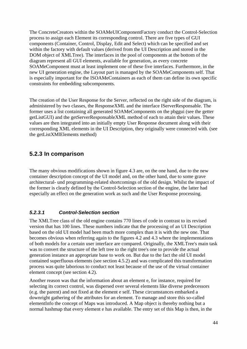
The ConcreteCreators within the SOAMeUIComponentFactory conduct the Control-Selection process to assign each Element its corresponding control. There are five types of GUI components (Container, Control, Display, Edit and Select) which can be specified and set within the factory with default values (derived from the UI Description and stored in the DOM object of XMLTree). The interfaces in the pool of components at the bottom of the diagram represent all GUI elements, available for generation, as every concrete SOAMeComponent must at least implement one of these five interfaces. Furthermore, in the new UI generation engine, the Layout part is managed by the SOAMeComponents self. That is especially important for the ISOAMeContainers as each of them can define its own specific constraints for embedding subcomponents.
The creation of the User Response for the Server, reflected on the right side of the diagram, is administered by two classes, the ResponseXML and the interface IServerResponsable. The former uses a list containing all generated SOAMeComponents on the pbggui (see the getter getListGUI) and the getServerResponsableXML method of each to attain their values. These values are then integrated into an initially empty User Response document along with their corresponding XML elements in the UI Description, they originally were connected with. (see the getListXMlElements method)
5.2.3 In comparison
The many obvious modifications shown in figure 4.3 are, on the one hand, due to the new container description concept of the UI model and, on the other hand, due to some grave architectural- und programming-related shortcomings of the old design. Whilst the impact of the former is clearly defined by the Control-Selection section of the engine, the latter had especially an effect on the generation work as such and the User Response processing.
5.2.3.1 Control-Selection section The XMLTree class of the old engine contains 770 lines of code in contrast to its revised version that has 100 lines. These numbers indicate that the processing of an UI Description based on the old UI model had been much more complex than it is with the new one. That becomes obvious when referring again to the figures 4.2 and 4.3 where the implementations of both models for a certain user interface are compared. Originally, the XMLTree's main task was to convert the structure of the left tree to the right tree's one to provide the actual generation instance an appropriate base to work on. But due to the fact the old UI model contained superfluous elements (see section 4.5.2) and was complicated this transformation process was quite laborious to conduct not least because of the use of the virtual container element concept (see section 4.2).
Another reason was that the information about an element e, for instance, required for selecting its correct control, was dispersed over several elements like diverse predecessors (e.g. the parent) and not fixed at the element e self. These circumstances embarked a downright gathering of the attributes for an element. To manage and store this so-called elementInfo the concept of Maps was introduced. A Map object is thereby nothing but a normal hashmap that every element e has available. The entry set of this Map is then, in the
44

final step of the XMLTree's processing, examined in the Control-Selection part where the element e is assigned a component.
Contrary to this work solely executed by the Crawler, the Control-Selection task in the new engine is shared between the five ConcreteCreators of the SOAMeUIComponentFactory. In the old engine the Control-Selection-Rules are embedded for the most part in the GUIMap file. This principle though was abandoned in the new version so that the rules were fully integrated into the code of the ConcreteCreators, in connection with the decentralization of the Control-Selection work.
5.2.3.2 Programming-related enhancements The shortcomings addressed to in this section have almost nothing to do with the redefinition of the old UI model. That is why the changes at this point will not be explained in-depth.
The former centralized User Response processing by the monolithic ResponseXML class was broken down and distributed to the several GUI components by using the IServerResponsable interface. Another drawback was the non-existence of interfaces which would structure and facilitate the access methods on the components available for the UI generation. Moreover, the introduction of the Factory Pattern enables a clear separation between the conduction of the Layout Rules and the generation work as such.
5.2.4 Format of the User Response
Without going into detail with the schemas (s. Appendix 2), it is noted here, that in the old version of the Client the structure of the User Response was nearly identical with the content of the corresponding UI Description. Both documents only differed in the values manipulated by the user within the task execution.
The new concept however stipulates that any information not relevant for further processing is dismissed. This affects especially the container-elements as their main purpose is it “just“ to structure the layout of an user interface (s. Section 4.1). That explains why the User Response of the new Client does not contain any container-elements but only those of the atomic tasks. So it is not possible, for instance, to derive from the User Response if a certain editTask was embedded in a GUI container or not.
5.3 The Server Due to a fine concept for managing the UI descriptions of a Service Composition the changes in the Server are more than irreducible. Worth mentioning is just that any UI Description is not modified by the Server any more at all, though even the former manipulations only included the add of a single XML element to the UI description.
45

6 Extension of the SOA-Me-Platform According to the database established in chapter 3 the features listed below were considered as the most significant ones of the SAP GUI. Derived from the analysis of the R/3 user interface they shall constitute the requirements for the new SOA-Me Platform. The seven features permit a classification into three groups Basic components of a GUI, in general
– Containers: Group boxes, Tabs, horizontal arranged elements
– Tables: Editable and non-editable tables
– Child Windows: Support of the context of tasks
Value helps
– Matchcode: Table based value help for input fields
– Autocomplete input field: Value help for input fields
Navigation and access elements
– Easy Access: Grouping of processes by means of a tree
– Command field: Fast access to processes via transaction codes.
Each feature to be implemented in the SOA-Me Platform has a different impact on the components of the present system including the current SOA-Me task model. To what extent each feature, except for the containers, is of relevance for an ERP user interface, its presentation on the GUI and the changes in the SOA-Me system that come along with it will be presented in this chapter. Each section is dedicated to one of the above components, except for containers, and follows a certain scheme. First the significance of each feature is shortly outlined and it is explained why it is important for an ERP system. Secondly, the SAP GUI exemplar and the SOA-Me exemplar are presented. Then the influence of each feature on the UI model and on the three SOA-Me components are regarded. In the UI model section, if reasonable, concrete examples are used for reasons of clarity, whereas the corresponding schemas are to be found in the appendix. The description of the changes in the several SOA-Me components are quite brief because the modifications are all in all minimal and would be rather bore the reader.
46

6.1 Basic components of a GUI, in general
The three features below are considered as important and basic for they are integral components of many GUIs of every type of application and not just ERP systems. As the preceding chapter 4 already discussed the implementation of containers this section will solely focus on tables and child windows.
– Containers: Group boxes, Tabs, horizontal alignment of elements
– Tables: Editable and non-editable tables
– Child Windows: support of the context of tasks
6.1.1 Tables
Significance Tables enable an efficient, clear and ergonomic recordation and display of single-lined data structures storable in tables [SAP01]. They can be used for edit, display and select tasks. These elements are assigned a high significance as they are used very often. Especially in the context of Matchcode-tables which are another major component of the SAP GUI (s. Section 6.2.1).
SAP GUI exemplar In comparison to other SAP GUI controls tables are equipped with relatively few accessory functions. A remarkable point about them is that the cells of a table are often highlighted with several colours as shown in figure 6.1. That is seemingly due to ergonomic issues enabling the user a better orientation when working on a table.
Figure 6.1: A table occurring in the “production planning” case study
47
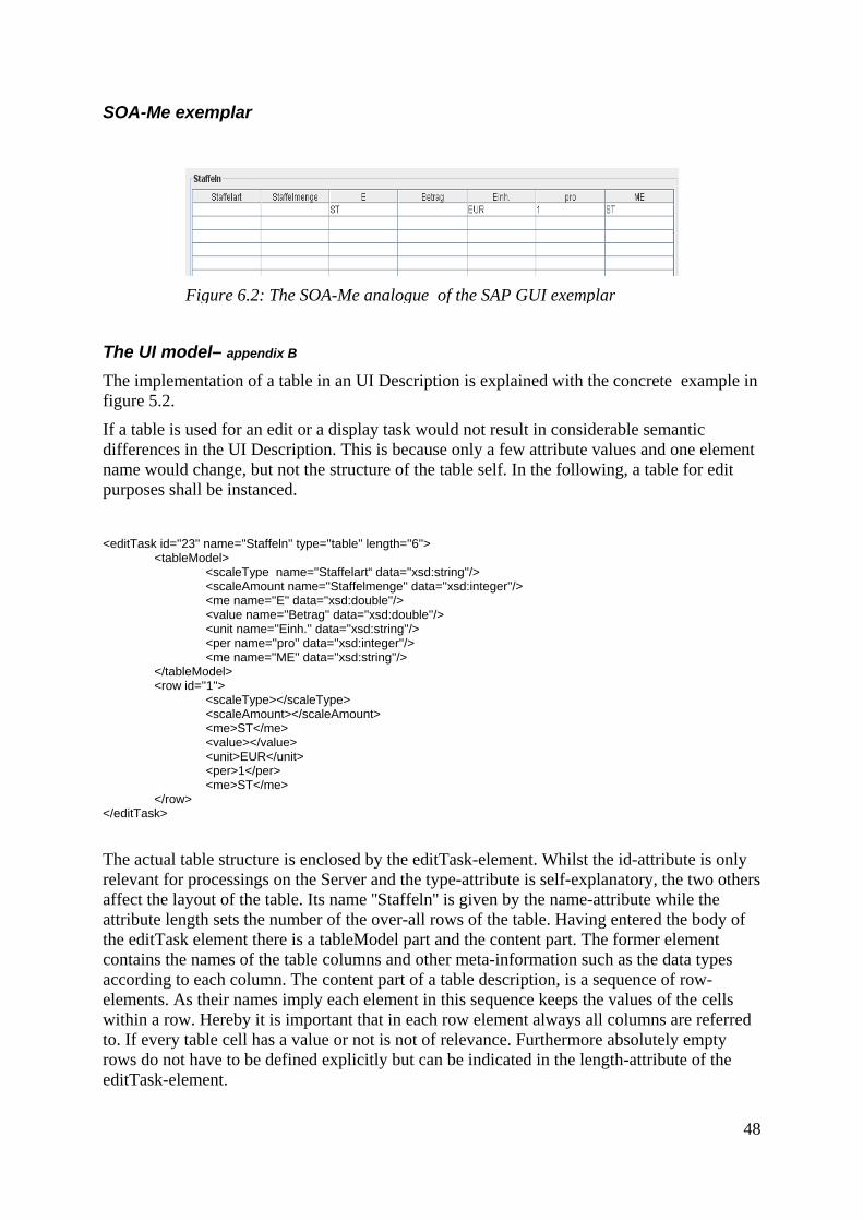
SOA-Me exemplar
Figure 6.2: The SOA-Me analogue of the SAP GUI exemplar
The UI model– appendix B
The implementation of a table in an UI Description is explained with the concrete example in figure 5.2.
If a table is used for an edit or a display task would not result in considerable semantic differences in the UI Description. This is because only a few attribute values and one element name would change, but not the structure of the table self. In the following, a table for edit purposes shall be instanced.
<editTask id=''23'' name=''Staffeln'' type=''table'' length=''6''> <tableModel> <scaleType name=''Staffelart“ data=''xsd:string''/> <scaleAmount name=''Staffelmenge'' data=''xsd:integer''/> <me name=''E'' data=''xsd:double''/> <value name=''Betrag'' data=''xsd:double''/> <unit name=''Einh.'' data=''xsd:string''/> <per name=''pro'' data=''xsd:integer''/> <me name=''ME'' data=''xsd:string''/> </tableModel> <row id=''1''> <scaleType></scaleType> <scaleAmount></scaleAmount> <me>ST</me> <value></value> <unit>EUR</unit> <per>1</per> <me>ST</me> </row> </editTask>
The actual table structure is enclosed by the editTask-element. Whilst the id-attribute is only relevant for processings on the Server and the type-attribute is self-explanatory, the two others affect the layout of the table. Its name ''Staffeln'' is given by the name-attribute while the attribute length sets the number of the over-all rows of the table. Having entered the body of the editTask element there is a tableModel part and the content part. The former element contains the names of the table columns and other meta-information such as the data types according to each column. The content part of a table description, is a sequence of row-elements. As their names imply each element in this sequence keeps the values of the cells within a row. Hereby it is important that in each row element always all columns are referred to. If every table cell has a value or not is not of relevance. Furthermore absolutely empty rows do not have to be defined explicitly but can be indicated in the length-attribute of the editTask-element.
48

This concept for describing tables was originally inspired by the approach used in the typeAny-model of the FERP-prototype although many modifications were finally done that make it unique. The most significant change was the introduction of the tableModel-element that establishes a central place for storing meta-information and constraints on, for instance, enumeration of rows by means similar to IDREFs. That would be possible because every row-element has a, at least locale, unique id-value. This centralization would furthermore result in a better readability of the table description as all relevant information on the table could be attained with a few glances.
Changes in SOA-Me
Client
Figure 6.3: Class diagram of SOAMeTable integration
The implementation of two interfaces is needed to make SOAMeTable serviceable as an edit and an display control. The setContent method sets the rows of the tables and the getter extracts them.
Server None, as the implementation of tables only affects the UI description which is not manipulated by the Server.
Editor Almost none. The item ''table'' must be merely added to the range of selectable ''types'' of an editTask and a displayTask, respectively.
Outlook The most crucial work on tables that is still to be done is to make them feasible as a SOAMeSelect component.
49
6.1.2 Child Windows
Siginificance Next to GUI containers child windows are probably one of the most important features of an user interface of any kind of system, especially complex ones. They supplement the current main user activity by displaying additional information. It is also possible to enable the user to make further inputs, specifications and selections. Child windows are significant as they can help the user by providing extra information on the context of a user task. Particularly, as dialog boxes they can convey direct and clear feedback to the users. Moreover child windows, too, allow a composition of tasks as containers do it, but with other means. Either a user task can be composed of many containers on a single screen, or certain sub tasks it are distributed to child windows.
SAP GUI exemplar The R/3 system distinguishes between two types of windows, the primary windows and the secondary windows. The latter are usually referred to as dialogue or popup windows. These have only supplementing functions and pop up in reaction to certain user actions. The main activities always take place in the primary window. In dialogue windows additional data can be entered, choices can be made or information error and consequences of actions are displayed. Though there may be multiple secondary windows at a time, only one can be worked with. This is due to the fact that dialogue windows in R/3 are “modal“. That means a dialogue takes over control of the system and must be closed first to continue work with other windows. [SAP04]
SOA-Me exemplar As in the R/3 system the SOA-Me system has primary windows and secondary windows. The former is always the main frame of the Client application whilst the latter are to be understood as separate child windows. User interfaces can be generated in these dialogue windows like in the primary windows without any constraints. The SOA-Me Client adopts the principle of “modal“ windows.
The UI model – appendix C
If a GUI is to be generated in the frame of the Client's application self or in a new child window is solely determined by the attribute frame. This belongs to the root element ui of a UI description. Currently there are only the two values “main“ and “child“ available. The default value is “main“.
Changes in SOA-Me Client In the Client, user interfaces are generated in so-called task areas, which are implemented by SOAMePanels. The primary task area is located in the main window of the Client application. Secondary task areas in turn are placed in child windows.
50

The user interface of a task which is marked with a “main“-value in the frame-attribute is generated in the primary task area of the Client. By contrast the value “child“ would result in an user interface that is generated in the secondary task area of a newly created child window.
It must be ensured that the over-all context of a user task is permanently maintained for the user when a sub task is worked on in a child window. This is important as any tasks provided in a child window should always only be supplementing for a current task in the primary window of the Client. To preclude that the main user interface in the primary task area and other active secondary task areas are accidentally cleared a special controller is used.
The TaskAreaController supervises the setting and the clear of the several task areas of a Client on the basis of the following set of rules.
1. if (oldFrame==main && newFrame==child) setTaskArea(newFrame); oldFrame = newFrame; 2. if (oldFrame==main && newFrame==main) clearAllTaskAreas(); setTaskArea(newFrame); oldFrame = newFrame; 3. if (oldFrame==child && newFrame==child) setTaskArea(newFrame); oldFrame = newFrame; 4. if (oldFrame==child && newFrame==main) clearAllTaskAreas(); setTaskArea(newFrame); oldFrame = newFrame; The oldFrame-variable refers to the last UI generated in the Client and the newFrame-variable refers to the new UI which is to be generated next. The setTaskArea method determines the task area for the new UI in which it should be generated. The task area may be for example a new child window as in case 3 above. The clearAllTaskAreas method clears all current existing task areas. That means that all child windows are disposed and the primary task area is made blank.
The instantiation of the TaskAreaController follows the Singleton Pattern to avoid conflicts and keep the variable oldFrame and newFrame unique.
Server None, as the implementation of tables only affects the UI description which is not manipulated by the Server.
Editor The value of the frame-attribute can be set on the main view of the UI Modelling Tool (see figure 5.2).
51

Outlook The controller above and its set of rules enable a steady maintenance of the context of the user tasks across a single session but not across multiple sessions. This is because each time a user terminates his Client all user interfaces currently shown in their task areas are cleared and disposed. That is especially critical if the user quits the programme while conducting a sub task t in a child window. By doing that, the next time he would start his Client and continue with t the primary task area and all other preceding sub tasks of t would be blank and not existent, respectively. A “regeneration“ of these task areas and their last user interfaces is not possible as their corresponding UI descriptions were not saved when the last session was terminated. Neither on the Client nor on the Server.
Saving the last status of a Client locally, that is on the computer it is actually installed on, is no option as the Client is user-oriented. Although this point may be debatable when considering that in an enterprise a user works most of the time at the same work station.
A possibility would be to save all task Ids of the current visible user interfaces and tasks, respectively, in a data structure and to send this to the Server to store it there in the user data base. In the course of the next session login of the respective user these task Ids would be then sent to the Client. Next, if the user wishes to continue his last task, a sequence of server requests would be done to attain the UI descriptions corresponding to the several task Ids. Having these a regeneration would be possible to provide again an appropriate context for a sub task.
However, less complex solutions are also imaginable. For instance, for task which has sub tasks assigned to there could be a special condition. It could say that an user either has to abort the main task or has to finish it with all its subtasks, before terminating the Client application.
Another way to cope with the problem, would be a guideline for the designer self, demanding not to model tasks with more than one sub task.
6.2 Value helps
Value helps are supplementary features for input fields. They help users to enter the correct values, often defined keys. These feature are assigned to a high priority due to the large amount of records and data an user have to cope with and because input fields are the most common elements of the SAP GUI (s. Table 3.1).
– Matchcode: Table based value helps for input fields
– Autocomplete input fields: Value helps similar to history fields for input fields
52

6.2.1 Support Elements
While analysing the SAP GUI (s. chapter 3) it was noticeable that quite a lot different pushbuttons with different functions were used in the SAP R/3 system. They were not only placed on the several tool bars but were also set on the work area in relation to various components. For instance, input fields had often pushbuttons for value helps. Diverse pushbuttons are pictured in figure 6.3.
Figure 6.4: Pushbuttons occurring in the work area
Although these were not considered in the extension of the SOA-Me system the issue aroused, where to place such supplementary features in the UI description at all. They are special as they are no mere pushbuttons but may hide certain functionalities, records or other data. First question is how to transport these via the UI description. And secondly, a method must be found to specify a relation between a supplementary feature and a component on the UI. The records or data, supplementary features come along with, are placed within the UI description in a separate section. This section's root element is the support-element. Below the first two element-levels of the UI description are depicted. Its first child element container encloses the actual description of the UI. All the elements corresponding to the supplementary features are included as successors of the support-element. <ui> <container> ... <editTask ......attachments=“idA idB ....“ /task> ... </container> <support> <autoComplete id=“idA“...>...< /autoComplete> <matchCode id=“idB“...>...</matchCode> </support> </ui> A relationship between a task and a supplementary feature can be set by means similar to
IDREFs [TMG+
06]. Thereby there are theoretically no constraints upon what task of the five available ones (container, editTask, controlTask, selectTask, displayTask) is to be coupled with which supplementary feature. That means a displayTask, for example, can be set in connection with an autocomplete feature in a UI description. But such a relationship would be simply ignored by the Client self as it would not make any sense. IDREFS is a data type for a xml attribute that refers to other attributes with a ID-data type and thus enables cross-references among elements in a document. This principle was adopted in this case, too, as to be seen in the code above. The editTask refers to the autoComplete and matchCode elements in the support-section via its attribute attachment with the Ids idA and idB.
53

However the attribute attachment- and the ID-attributes have the data type String instead of IDREFS and ID, respectively. This is due to an implementation-related problem as the JDOM API [HM04] that the Client uses to process XML documents is unable to handle the data types IDREFS and ID. In the consequence, the underlying concept of IDREFS of interlinking elements with each other had to be emulated in the Client. The necessary conditions were given as each element in the UI description has an id-attribute (needed for processings on the Server). Depending on what expedient elements in the support-section a task-element refers to, its presentation on the GUI is outfitted with the corresponding supplementary features, for example in the form of pushbuttons. Besides, if an editTask-element, for instance, refers to more than one autoComplete-element the records of that autoComplete-element are taken whose Id appears last in the list of Ids of the attachment-attribute of the editTask-element. The contents of the elements of the supplementary features depend on the functionalities a feature provides on an user interface. That is why there can be various XML structures as it is shown in the following sections. It can be for example a list of elements (s. autoComplete feature), a description of a table (s. Matchcode feature) or even another user interface description. The emulation of the IDREFS-concept happens in the AttachmentFactory.
6.2.2 Matchcode
Siginificance Matchcodes are an efficient, user friendly aid that are provided by certain input fields. They help the user to locate records for which he does not know the key field values. The SAP R/3 system distinguishes between the Matchcode types Hit List and Restrict Value Range. Whilst the latter provides a complex category search, the former is actually nothing else as a table that lists the possible keys of a field and their descriptions. In this thesis Hit Lists are regarded, in particular, as a good number of them occurred when conducting the case studies. These elements are moreover considered important as they support the user in handling with amounts of records and keys difficult to cope with.
54

SAP Gui exemplar In figure 6.4 a Hit List is pictured. It pops up when the
icon of an input field is clicked. This icon and its pushbutton appears whenever a field is entered that has a Matchcode. As not all fields provide this functionality. The values which are to be inserted into a field are placed in the KArt-column. Furthermore a search function and a sorting function can be used amongst others. If a certain row is selected or double-clicked the respective value is automatically set in the input field.
Figure 6.5: Hit List in the CC case study
SOA-Me exemplar The current SOA-Me Hit List object is a simple table in a separate window that pops up when the respective pushbutton of an input field is clicked. In contrast to the SAP GUI exemplar this icon and its pushbutton are permanently to be seen and do not appear in reaction to a user's action. If a certain row of the table is selected or double-clicked the respective value is made available for the input field component.
The UI model A Matchcode is described in the UI description according to the principle used for Support-Elements (s. Section 6.2.2). It is specified by the element matchCode and the value “hitList” for the attribute type. The XML element encloses a element structure based upon the table description (s. Section 6.1.1). However the defined table must have exactly one column-element with the name “key“ to be valid as a Hit List. The column “key” should contain those values which are to be entered into a corresponding input field. <matchCode name="Kostenstellentypen" type=“hitList" id="43"> <tableModel> <key name="KArt" data="xsd:string" /> <description name="Bezeichnung" data="xsd:string" /> </tableModel> <row id="1"> <key>1</key> <description>Fertigung</description> </row> <row id="2"> <key>2</key> <description>Hilfskostenstelle</description> </row> ... </matchCode>
55
Client Each SOA-Me component that is to be set up with a Hit-List feature must implement the IMatchCodeHitList interface.
Server None, as the implementation of Matchcodes only affects the UI Description which is not manipulated by the Server.
Editor The most comfortable way to model and integrate such supplementary elements into the UI description would be to use the UI Editor Tree in the UI Modelling Tool. However that function is not available yet. But as the whole UI description document can be developed in a separate text editor outside of the Modelling Tool, it is already possible to use the supplementary features although the usability of the UI designing task would surely suffer. Furthermore the supplementary elements should be added to the UI description after having finished the Service Composition for a business process. This is recommended to avoid ID conflicts since every element in the Service Composition must have an unique ID. This circuituos method though would not make sense in an ERP environment because the business process would be too large and the amount of data too vast.
Outlook The most crucial work on Hit Lists that is still to be done are the implementation of a search and sorting function. The former function is especially important for Hit List may contain more than 100 rows.
6.2.2 Autocomplete input fields
These value helps appear as a drop down menu of an input field. When the user enters a string of characters the feature is invoked and a list of words, which are similar to the entered string, is presented to the user. There are two types of autocomplete value helps. Static ones has a list whose entries cannot be dynamically changed. Such static lists are set in the UI description according to the principles used for Support-Elements (s. Section 6.2.2). By contrast non-static autocomplete features contain lists whose entries can be dynamically changed in the course of a business process.
Outlook Whilst static autocomplete fields are already available in the SOA-Me Platform, their non-static counterparts still has to be implemented. This especially requires modifications in the Server and the user data base.
For further information on these kind of value helps please address the Table of Features (appendix E).
56

6.3 Navigation and Access elements Navigation and Access elements are especially important in complex systems where many tasks and applications, in general, are available.
– Easy Access: Grouping of processes and tasks by means of a tree
– Command field: Fast access to tasks via transaction codes.
Unlike the other features neither the Easy Access nor the command field have an impact on the UI model because they are are fixed components of the GUI of the Client and are not generated. That is why the two features above will not be examined for their influence on the UI model but on the Client-Server interface. This interface defines the functions which the Server provides to the Client to communicate.
6.3.1 Easy Access
Significance The Easy Access user menu is a tree structure in the SAP R/3 system which enables a clearly arranged overview of applications a user may perform and other items. It is assumed important for two reasons. First, the menu is used very often. Almost all work steps and applications raised in the case studies commenced by accessing a certain item in the user menu. Secondly, it is hard to imagine any other GUI feature more suited to reflect the needs of an ERP system. Such kinds of systems are aimed at covering the entirety of an enterprise's business processes and applications to provide these then to the user. As this includes many departments, roles and hierarchy structures a reasonable and appropriate means to access and present them is required.
SAP GUI exemplar Below in figure 6.5 a detail of the SAP standard menu is pictured which appears as a tree structure on the left of the screen. It offers a complete overview of the items of the SAP R/3 system, such as transactions, reports or Web addresses. By contrast the SAP Easy Access menu is the personalized version of it. Normally it is the first screen a user sees after having logged on the system. It provides a user-specific point of entry into the SAP system and thus the tree only includes those items which a user needs to perform his daily tasks. [SAP05]
57

Figure 6.7: SOA-Me Process menu Figure 6.6: Detail of the SAP
standard menu
SOA-Me exemplar The SOA-Me analogue is picture in figure 6.6.The concept of using a tree structure for accessing applications or transactions was implemented for the process list and toDo list of the Client. The former gives the user an overview of the processes he is allowed to start. And the latter list informs him about the current tasks he has to perform. It was inevitable to adapt both lists as the correlation between a task and the process it belongs to has to be ensured for the user.
In comparison to the SAP GUI exemplar and in SAP terms, the Client actually only offers a Easy Access user menu. That is due to the fact that the processes a user can start are defined by a third person as it would be the system administrator in the SAP R/3 system.
Client-Server interface Process List The information on the processes a user is allowed to start are sent to the Client within the login activity nonrecurring during a session. The respective method is
login(String userName, String password) : java.util.HashMap[]
An array is returned whose single items are hashmaps. Each of them refers to one process and has three key-value-sets. [SOAMe06]
Key XML-Type key XML-Type value Content pid xsd:string xsd:string Process ID name xsd:string xsd:string Name of the process description xsd:string xsd:string Short description
Table 6.1: Return of the login-method
58

The tree path of a process is included in its name-property as follows node1.node2....node n.process name with the nodes i representing the single tree nodes in the process tree. As the delimiter is a “.“- character these should not be integrated into the name of a process or of a node. ToDo List The information on the tasks a user is allowed to perform are sent to the Client when the ToDo-List is requested from the Server. This request is repeated in certain time intervals during a session. The respective method is
getToDoList() java.util.HashMap[]
An array is returned whose single items are HashMaps. Each of them refers to one task and has four key-value-sets. [SOAMe06] dad sd sdgsaf
Key XML-Type key XML-type value Content tid xsd:string xsd:string Task ID name xsd:string xsd:string Name of a task description xsd:string xsd:string Short description abortable xsd:string xsd:boolean true, if the respective
process can still be aborted, otherwise false
Table 6.2: Return of the getToDoList-method
The tree path of a task is included in its name-property as follows node1.node2....node n.process name p.task name t with the nodes i representing the single tree nodes in the process tree. As the delimiter is a “.“- character these should not be integrated into the name of a task or of a node. To point out for the user that a task t belongs to a process p their respective paths should contain the same nodes i in the same order. Additionally to that the last path component of the task t must be the name of the process p.
Changes in SOA-Me Client As the former process list and task list were implemented with normal list elements, a tree had to replace them to provide the Easy Access principles. Due to the incompleteness of a JTree or any other existent tree element for this purpose, a custom one was developed. In the following the implementations are for the most part explained with the task list as they also apply for the process list.
The ActionListTree, ActionListTreeModel and ActionListTreeNode extend the java classes JTree, DefaultTreeModel and DefaultMutableTreeNode. Both the process list and the task list
59
uses them. While the process list of the Client is only set up once a time during a session, the task list is updated every few seconds by the updateTree method of DrawController. This method creates a new ActionListTreeModel instance out of the most recent information on the tasks sent by the Server. Then it simply replaces the current model of the task list by the newly set up one. A kind of intelligent adjustment of the current model on the basis of the new task information however would not be possible. This is because the unambiguity of a node in a tree, in general, depends exclusively on the unambiguity of its tree path. That means that any node in the task list (including leaves) is identified by its tree path. The latter in turn is determined by the several names of nodes it contains and by their order.
In consequence of that a completely new model has to be set for the task tree with every update because data not covered by the order of names in a tree path may change like task IDs or short descriptions.
Server None, as the path of a process or task is included in its name property which is not manipulated by the Server.
Editor None, as the designer only has to add the path to the name of a process or to the name of task, respectively. It is also possible to set no path at all, so that the name property only includes the name self.
Outlook:
It is recommended to implement functions that enable a personalization of the process list by setting favourites. Furthermore the entries in the task list must be equipped with information on the concrete instance of a task. This is required in the case that a task of a process is invoked more than one time. Facing this a concept for displaying several instances of a task must be developed. Concrete information on an instance of a task would be for example certain variable-values within a task or simply information about the date or time of a task.
6.3.2 Command field
Please address the Table of Features (appendix E)
60

7 Conclusion and Outlook Within the scope of this thesis it was shown that the various number of features of an ERP (Enterprise Resource Planning) user interface can be reduced to a small subset of the most significant ones for an ERP system. Analysing the SAP GUI of the SAP R/3 system as a concrete example revealed that three groups of user interface features are relevant within an ERP domain:
– Containers, tables and child windows as basic components of a GUI, in general which structure tasks and actually provides the room and space for all other components and data structures. For instance, without tables records from data bases, which belong to the core of every ERP system, could not be presented properly. Without group boxes, which are simply panels, being used to structure tasks complex user interfaces with dozens of fields would be purely confusing.
– Value helps as crucial supporting elements for input fields
which help users to cope with amounts of not bearable data and thus support the correct conduction of user tasks and hence the correct execution of business processes.
– Navigation and Access elements in the form of trees which actually make the processes and tasks within an ERP system accessible for the user without to stress him with the inner complexity of the system.
Having determined these features and with them the requirements for user interfaces which are dynamically generated and are to be used in ERP domains, a new task model was developed. The aim was it to conceive a task model, the basis of every concept for user interface generation, that would cover all the requirements above demanded by an ERP system. By breaking down the existing task models the user interface model was detected to be the only component of the task model that would be affected by an extension of the capabilities of generated user interfaces. The development of the new UI model resulted in a concept that adopted the strengths of the model of Gutbier [Gut07]. A lightweight approach, in a positive sense, that is free of superfluous elements, intuitively to use and that, above all, is able to describe containers. The impact of the requirements stated above on the model self were rather minimal. In contrast to the consequences on the SOA-Me Platform that had to be modified to make the new task model and thus the enhanced generated user interfaces feasible. The most modifications were done in the SOA-Me Client whose UI generation engine had to be changed. However the SOA-Me Editor experienced the most serious changes for the old concept for modelling abstract user interfaces was completely abandoned and replaced by another one. This was necessary not only for reasons of the structural changes of the UI model but also because of the grave usability deficiencies of the old means to model the UI description. Furthermore, not all features being aimed for, namely the dynamic autocomplete fields and the command field, could be implemented in the SOA-Me system.
61

All in all, the current implementations of the features are quite rudimental which leaves space for future work. – The SOA-Me-User Client is far away from being user-friendly as SAP R/3. While this
thesis rather aimed at the functional aspects of an ERP user interface, future work could target a sophisticated integration of non-functional aspects and supplementary features. Actually it is the large number of tiny details and inconspicuous functions which distinguishes the SAP GUI and thus make the work with the R/3 system acceptable for the day-to-day work
Furthermore, the UI Modelling Tool as an integral part of the Editor and the SOA-Me Platform as a whole must be extended, too, regarding its functionality and usability. – At the beginning in chapter 2 it was elucidated that the flexibility of a SOA system which
incorporates user tasks depends on the means to change a Service Composition and on the generation of user interfaces. However the means to model abstract user interfaces is also a significant factor in this context. As long as abstract user interfaces cannot be changed in an acceptable manner in response to changes of data flows within a business process, the respective SOA system will have a bottleneck when modifying business processes.
62

Bibliography [Bai06] Coreen Bailor (2006-07-05), For CRM, ERP, and SCM, SAP Leads the Way. http://www.destinationcrm.com/articles/default.asp?ArticleID=6162, last access 2007-08-23
[Bie04] Thomas Bierhance, Inside JComboBox: adding automatic completion, latest update: 02.11.2004. http://www.orbital-computer.de/JComboBox/#usage, last access 2007-08-23 [Bru06] Mark Brunelli (09 Nov 2006), Smaller vendors challenge SAP, Oracle in ERP market. http://searchoracle.techtarget.com, last access 2007-08-23
[dBFM92] Dennis J. M. J. de Baar, James D. Foley, and Kevin E. Mullet. Coupling application design and user interface design. In CHI ’92: Proceedings of the SIGCHI conference on Human factors in computing systems, pages 259–266, New York, NY, USA, 1992. ACM Press. [Gut07] Michael Gutbier. Concept and Implementation for Integrating User Interface Descriptions into BPEL Processes. Master's thesis, Universität Hannover, April 2007 [HM04] Jason Hunter and Brett McLaughlin (2004), JDOM v1.0. http://www.jdom.org/
[KNS92] G. Keller, M. Nüttgens, and A.-W. Scheer. Semantische Prozemodellierung auf der Grundlage ”Ereignisgesteuerter Prozeketten (EPK)”. Number 89 in Veröffentlichungen des Instituts fr Wirtschaftsinformatik. Scheer, A.-W., 1992 [Kön07] Christoph König, Entwurfsvergleich einer SOA-Anwendung auf SOA-Me- und BPEL- Basis. Bachelor's thesis, Universität Hannover, August 2007 [Lüb07] Daniel Lübke, An Integrated Approach for Generation in Service-Oriented Architecture. Dissertation, Universität Hannover, 2007 [Lüe05] Tim Lüecke. Development of a concept for creating and managing user- interfaces bound to business processes. Master’s thesis, Universität Hannover, November 2005 [LV03] Quentin Limbourg and Jean Vanderdonckt. Comparing Task Models for User Interface Design, pages 135-154, July 2003 [MN05] Jan Mendling and Markus Nüttgens. EPC Markup Language (EPML) - An XMLBased Interchange Format for Event-Driven Process Chains (EPC). Technical report,Vienna University of Economics and Business Administration, March 2005
63
[RRZN06] Regionales Rechenzentrum für Niedersachsen/ Leibniz Universität Hannover, SAP R/3 Grundlagen Einführung für Anwender-Release 4.7, 3.unveränderte Auflage, September 2006 [SAP01] SAP AG, BC - SAP Style Guide Release 4.6C. SAP AG, 2001 [SAP02] SAP AG, SAP Reference Lists Version 1.2. SAP AG, 05 November 2002 [SAP04] SAP AG, SAP R/3 Style Guide. SAP AG, 16 August 2004
[SAP05] SAP AG, SAP Easy Access. http://help.sap.com/saphelp_erp2005/helpdata/en/5f/7935422e5fb86be10000 000a155106/content.htm, www.help.sap.com, 2005, last access 2007-08-23 [SAP06] SAP AG, SAP Annual Report 2006. SAP AG, 2007 [SAP07] Press Release (July 19, 2007), SAP Announces Preliminary 2007 Second Quarter and Six Months Results. MarketWatch,.last access 2007-08-23
[SOAMe06] SOA-Me-Client-Team, SOA-Me-Integrationsserver-Team, SOA-Me Schnittstellenbeschreibung v02 Client <–> Integrationsserver. SE Softwareprojekt WS06/07, Leibniz Universität Hannover, 08/12/2006
[TGS07] Nick Tomson, Brett Gornick, Brian Strobridge, and John Reusch, SAP GUI Navigation. Western Michigan University, http://homepages.wmich.edu/~e2konopk/BUS%20Project%202%20AND% 204.htm, 2007
[W3C04] W3C (28 October 2004), XML Schema Part 2: Datatypes Second Edition. http://www.w3.org/TR/xmlschema-2/, last access 2007-08-23 [W3C06] W3C, XML Schema 1.1 Part 1: Structures, http://www.w3.org/TR/xmlschema11-1/, last access 2007-08-23 [Wal04] Gerd Waloszek, R/3 History in Screen Shots, SAP AG, Product Design Center – Last revision: 04/16/2004 , last access: 2007-08-23
[Wik07a] Wikipedia: SAP AG, http://en.wikipedia.org/wiki/SAP_AG. last access 2007- 08-23 [Wik07b] Wikipedia: Enterprise resource planning, http://en.wikipedia.org/wiki/Enterprise_resource_planning. last access 2007- 08-23 [Wik07c] Wikipedia: SAP R/3, http://en.wikipedia.org/wiki/SAP_R/3. last access 2007- 08-23
64

[WSV05a] Stefan Weidner, Heino Schrader, and Martin Voß. Integrations-Fallstudie CO (SAP R/3 Enterprise). SAP Hochschulkompetenzzentrum, HCC Otto-von- Guericke-Universität Magdeburg, 23/02/2005
[WSV05b] Stefan Weidner, Heino Schrader, and Martin Voß, Integration-Fallstudie PP (SAP R/3 Enterprise). SAP Hochschulkompetenzzentrum, HCC Otto-von- Guericke-Universität Magdeburg, 23/02/2005
65
List of Figures
Figure 2.1: Structure of the SOA-Me Platform; [Lüb07]
Figure 2.2: EPC elements; [Lüe05]
Figure 3.1: The SAP GUI and its view elements [TGS07]
Figure 3.2: a typical SAP GUI screen with some of the characteristic elements
Figure 3.3: Containers on the SAP GUI
Figure 3.4: Containers on the GUI of Gutbier's User Client [Gut07]
Figure 4.1: Simple example of an user interface to demonstrate the integration of containers in UI models
Figure 4.2: Example modelled on the old UI model
Figure 4.3: Example modelled on the new UI model
Figure 4.4: Class diagram of the new UI model
Figure 4.5: Class diagram of the old UI model
Figure 5.1: Modelling an user interface
Figure 5.2: UI Modelling Tool
Figure 5.3: Class diagram of the old UI generation engine.
Figure 6.1: A table occurring in the “production planning” case study
Figure 6.2: The SOA-Me analogue of the SAP GUI exemplar
Figure 6.3: Class diagram of SOAMeTable integration
Figure 6.4: Pushbuttons occurring in the work area
Figure 6.5: Hit List in the CC case study
Figure 6.6: Detail of the SAP standard menu
Figure 6.7: SOA-Me Process menu
66

List of Tables
Table 2.1: Four atomic types of tasks; [Lüe05] Table 3.1: Number of occurrences of few components of the SAP GUI Table 3.2: Row concerning Containers from the Table of Features Table 3.3: Row concerning Easy Access from the Table of Features Table 5.1: Example of some Control-Selection rules Table 6.1: Return of the login-method Table 6.2: Return of the getToDoList-method
67

Appendix
The Schema of the UI description is included on the enclosed CD.
68

Appendix A: UI Descriptions for figures 4.2 and 4.3 Figure 4.2 <ui> <edit id=’1’> <informationObject> <a name=’A’ > <textfieldB name=’B’ length=’100’ type=’string’/> </a> </informationObject> </edit> <select id=’2’ multiple=’false’ nullable=’false’> <data> <informationObject> <a name =’A’> <buttongroupC name=’C’> <radiobuttonD name=’D’ type=’boolean’/> </buttongroupC> </a> </informationObject> </data> <selection> <informationObject> <a name =’A’> <buttongroupC name=’C’> <radiobuttonE name=’E’ type=’boolean’/> </buttongroupC> </a> </informationObject> </selection> </select> </ui> Figure 4.3 <ui> <container name=’A’> <editTask name=’B’ length=’100’ type=’Textfield.string’/> <container name=’C’ type=’buttongroup’ multiple=’false’ nullable=’false’> <selectTask name=’D’ selected=’false’/> <selectTask name=’E’ selected=’false’/> </container> </container> </ui>
69

Appendix B: Schema for tables <?xml version="1.0" encoding="UTF-8"?> <schema xmlns="http://www.w3.org/2001/XMLSchema" elementFormDefault="qualified" xmlns:tns="http://www.example.org/user" > <schema> <element name=''editTask'' type=''tns:soame-table''> <attribute name="id" type="string"/> <attribute name="name" type="string"/> <attribute name="length" type="string"/> <attribute name="type" type="string">table</attribute> <attribute name="description" type="string"/> <attribute name="attachments" type="string"/> </element> <complexType name=''soame-table''> <element name=''tableModel'' type=''tns:soame-tableModel''/> <sequence maxOccurs="unbounded" minOccurs="1"> < element name=''row'' type=''tns:soame-tableRow''/> </sequence> </complexType> <complexType name="soame-tableModel"> <sequence maxOccurs="unbounded" minOccurs="1"> <element name=''COLUMNNAME1'' type=''tns:soame-tableColumn''/> </sequence> </complexType> <complexType name="soame-tableRow"> <sequence maxOccurs="unbounded" minOccurs="1"> <--! Für jedes tableColumn-Element, das im tableModel-Element vorkommt, muss es hier ein Element geben, das den gleichen Namen trägt wie das entsprechende tableModel-Element --> <--! Außerdem muss der Type eines soame-tableCell-Element gleich dem entsprechenden Type des tableColumn-Elements sein --> <element name=''COLUMNNAME1'' type=''tns:soame-tableCell''/> </sequence> <attribute name="id" type="string"/> </complexType> <complexType name="soame-tableColumn"> <attribute name="name" type="string"/> <attribute name="type" type=''tns:columnType"/> </complexType> <simpleType name=''soame-tableCell'' type=''tns:columnType''/> <simpleType name=''tns:columnType''> <xs:restriction base=''string"> <xs:enumeration value="string"/> <xs:enumeration value="boolean"/> <xs:enumeration value=''integer"/> <xs:enumeration value=''double"/> </xs:restriction> </simpleType> </schema>
70

Appendix C: Schema for the ui element <?xml version="1.0" encoding="UTF-8"?> <schema xmlns="http://www.w3.org/2001/XMLSchema" elementFormDefault="qualified" xmlns:tns="http://www.example.org/user" > <schema> <element name=“ui“ type=“tns:soame-uiDescription“> <attribute name=“id“ type=“string“/> <attribute name=“frame“> <simpleType> <restriction base=“string“> <enumeration value=“main“/> <enumeration value=“child“/> </restriction> </simpleType> </attribute> </element> </schema>
71
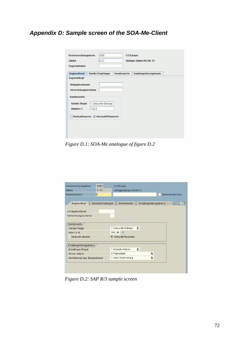
Appendix D: Sample screen of the SOA-Me-Client
Figure D.1: SOA-Me analogue of figure D.2
Figure D.2: SAP R/3 sample screen
72

Feature Comment Effect on task model Effect on UI generation engine Other parts of the Client
+ Containers on the user interface like Tabs or containers with horizontally arranged components
– enable (hierarchically) structuring tasks on a user interface
– is used very frequently to access the many transactions in a comfortable way
– support of the context of a user task or user interaction
– efficient presentation of data in a sophisticated manner
- adaptation of M.Gutbier 's task model with (all changes reserved), possible use of additional attribute “type“ for complex elements to specify the style of a container
- new engine for the user interface generation
++
+ Tabs – support of the context of a user task or user interaction
– efficient presentation of data in a sophisticated manner
– reduce of the number of screens a user has to conduct
– improve clarity and simplify navigation
- adaptation of M.Gutbier 's task model with (all changes reserved), possible use of additional attribute “type“ for complex elements to specify the style of a container
- Navigating through the panes of a tabs container can be done by using the “<“-pushbutton or the „“>“-pushbutton - Navigating through the several panes of a tabs container can be done pressing Enter when all required fields are filled out - All panes of a tabs container also be selected from a list which is set visible when pressing a certain pushbutton
73

Feature Comment Effect on task model Effect on UI generation engine Other parts of the Client
+ Date chooser – already available
– SAP Easy Access Menu - Thematical Grouping of Transactions by means of a tree component. The Easy Access navigation structure can be adapted to the Process List in the SOA-Me-Client
– is used very frequently to access the many transactions in a comfortable way
– names of transactions can be ambiguous but the tree path to a single transaction is univocal
– ERP system provide lots of transactions to conduct. Given that it is necessary to group the transactions or , in the context of the SOA-Me-Platform, processes.
As the Process List in the SOA-Me-Client does not base on the SOA-Me-task model or its UI Description scheme this feature would not affect the task model.
As the Process List in the SOA-Me-Client does not depend on the SOA-Me-task model or its UI Description scheme this feature would not affect the UI generation engine.
- the Process List must be implemented as a Process Tree
– Tables - efficient and clear presentation of data - can be editable or not - occur very often - basic requirement for other significant features like Hit List Tables
– the content of a table and its meta-information must be stored in the task model
– tables can be defined as edit tasks or display tasks
– description of tables in the task model may orient to the approach of the FERPX Project
- corresponding extensions of the UI generation engine and the pool of GUI components
/
74

Feature Comment Effect on task model Effect on UI generation engine Other parts of the Client
- Child windows (including dialog boxes)
- enable the appropriate presentation of sub tasks - the context of each sub task and its child window, respectively, must be clearly visible
75

Feature Comment Effect on task model Effect on UI generation engine Other parts of the Client
- Autocomplete for texts in Input Fields
– support fast and efficient operations on Input Fields
– occurs very often – management of the non-
static autocomplete entries follows the concept of temporal locality. A user is likely to reference the same inputs at one point in time he referenced at some other point of time in the recent past.
– there are non-static list of autocomplete entries and static ones which cannot be changed by a user
– each user is assigned a personal non-static list of autocomplete entries
– a non-static list is persistent over several user sessions
– the non-static lists of autocomplete entries may be sent permanently along with the task list and thus, do not effect the task model
– the static list is integrated into the task model and there, linked to potential Input Field elements.
– Question arises if the information about such a static list should be simply annexed to the actual UI Description or really embedded in the latter within Input Field elements.
Effect on Server
– Entries of the non-static
autocomplete fields are stored in the user data base, one entry set for each suer
– use of autocomplete capable Input Fields implemented with extended textfields or comboboxes [Bie04]
– operation mode similar to the functionality of the input field of the Web Search on the Google Toolbar
/
76

Feature Comment Effect on task model Effect on UI generation engine Other parts of the Client
- Value Help – non-editable but single rows are selectable
– occur in conjunction with Input Fields
– are used very often – support users to find
correct Ids to corresponding names and terms
– see feature “Tables“ – these tables has to be
explicitly marked as Hit List Tables
– as autocomplete entry lists they must be linked to potential Input Fields in the task model
– Question arises if the information about such a static list should be simply annexed to the actual UI Description or really embedded in the latter within Input Field elements.
• Provision of sorting functions • A cell which has the focus is
highlighted • Table columns and table rows
are highlighted with colours different to the background colour of the GUI
• Phonetic search funtion
- When an input field has the focus, a small pushbutton appears to the right of the field (normally invokes a Hit List value help)
The direct connection between input field and the value help must be recognizable
- Editable tables Occurs often. Important for applications where huge amount of data must be processed
77

Feature Comment Effect on task model Effect on UI generation engine Other parts of the Client
- Command field (transactioncodes)
Are a good gain for experienced users who wants to work more efficiently by using a quick access method via transactioncodes
None, as the command field is static component of the Client
Automated of the text into High-case letters. Integration of a history field for the command field
Restrict Value Range- value help
Is used for searching larger pools of keys (ca. 1000), but not mentioned in the case studies.
Absolutely separated from the task model. Probably a data base must be integrated to allow the search on such amounts of keys. That is why an explicit channel between the Client and the Server apart from the “UI description-User Response“ would make sense.
Generation within a child window. Context between input field and the seach results must be visible at first glance.
- Immediate invocation of an user task
More usability If a task list is empty and process is selected by the user, the first task of the process (if executable by the user) shall be invoked automatically. In general: If there is no more than one user task selectable, the task of the respective process is invoked.
- Process and user task title bar
Provides to the user a better overview of his current activities
- Client display which task of which process is currently conducted by the user
78

Feature Comment Effect on task model Effect on UI generation engine Other parts of the Client
- Toolbars The question is which functions are provided by which toolbar? Especially the print-function on the standard toolbar are important (did not occur in the case studies). However their implementation would be very complicated. The items in the application toolbar depends on the current application and task, respectively. --> quite a lot of additional work.
Not analysed yet
Static component of the Client whose contents are partially dependent on the current user task
- Filechooser for loading and saving .txt files
As not used at all in the case studies and as they occurred once during the whole analysis they are assigned a low priority. According to screenshot the default data format is „.txt“ --> Copy Paste would do it, too
Not analysed yet
Implementation via an ordinary file chooser control
+
- Standard toolbar Static, the pushbuttons and functions, respectively, on the toolbar provides search functions and navigation functions
Business logic: Navigation functions like “Last screen“ or “First screen“ are criticak because of the explicute persistence of the SOA-Me system.
79

Feature Comment Effect on task model Effect on UI generation engine Other parts of the Client
- External help functions which support the user (not value helps)
Are not significant for the business process self but for tutorials, training sessions and user support
Implementation is similar to the implementation of value helps like Matchcodes as they are supplementary features.
o Usability
Every activated pushbutton has a hover text – Required fields are tagged with
small check marks – Committing by pressing Enter or
pressing a pushbutton – When all required field are filled
out, committing them by pressing Enter sets visible the short descriptions of the respective fields.
Several list selections: Singe-line and multi-line selections
are possible. Lines can be also selected by
activating kind of check boxes within a line, but by doing so no check marks are set but the colour of a line changes. This is probably for reasons of usability.
The actual user interface with its controls is always placed in the upper-left-hand side corner of the work area
“Pulsating“error message in the status bar jedes [aktivierte] Icon mit Hover-Text
Normally, every field which has the focus is highlighted.
The Easy Access menu and standard menu , respectively, renders it cells in many different way
- Usage of shortcuts and pushbuttons integrated in the toolbars
Provide enhanced usability - -
80

Feature Comment Effect on task model Effect on UI generation engine Other parts of the Client
- User preferences and settings
Provide enhanced usability Settings for colours, fonts, cursor and clipboard
-Status bar Meldungen sind auch über Dialogboxen realisierbar.
The frame-attribute-value of the root element ui of the UI description can be set with „statusbar“. However the UI description must not have other components than a single display task with normal text.
Like a normal UI description
- Context menus Too complicated and there are no functions within a context menu which cannot be invoked by other means, too
- Intelligent built-in text editor
Superfluous gadget for an external text editor would do it, too.
81