Embed Size (px)
Citation preview

Analysis and simulation on two types of thrust reversers in an aircraft engine
Feng Tian, Jingwu He, Yuexi Xiong and Yanxiong Zhaoa
School of Aeronautical Science and Engineering, Beijing University of Aeronautics and Astronautics, Beijing, China
Abstract. With rapid development of new composite material and manufacturing , innovative engineering solutions are supplied to the advanced nacelle, such as integrated propulsion system(IPS) , carbon-fiber composite inner skin by single-piece molding process�which offers
a reduction in fuel burn and less noise produced by engines. The advanced nacelle has an O-duct thrust reverser demonstrator whose composite structure is in the form of an “O” as opposed to the traditional “D-duct”. A comparative study is to be conducted to investigate the differences between the latest O-duct and conventional D-duct in numerical approaches. To focus on the quantitative analysis of thrust reverser’s operation, this paper mainly uses CATIA/Digital Mock Up(DMU) to simulate under deployment and stowed conditions of two different thrust reverser. After comparing the structural weight, the design models of blocker door are built for kinematic analysis of relevant mechanism and simulation. The results show that simplified design and elimination of multiple interfaces generates weight saving, O-duct improves airflows within the engine, meanwhile D-duct has excellent cost effective and maintainability.
1 Introduction
1.1 Thrust reverser
Modern large passenger aircraft have great promotion on both the maximum takeoff gross weight and takeoff speed, more runway length are required to takeoff and landing. To face with the ever growing airport flow and varieties of emergency conditions, we need reliable deceleration system to reduce distance of landing or rejected takeoff effectively. Till now on, there are many ways for airliner to slow down, such as wheel brake, spoiler for aerodynamic braking, thrust reverser system, drag parachute and so on [2]. Though most of modern airliners are equipped with thrust reversers, the design of thrust reversers has influence on engine nacelle’s weight and wing performance, as well as cruise speed. Those parameters decide overall operation and maintenance cost to a certain extent. GE’s research suggests that the weight of thrust reverser accounts for thirty percent of the whole nacelle, especially for turbofan engines whose fan diameter are over 2.5 meters, and the air leakage and pressure loss caused by the thrust reverser leads to 0.5~1.0% increase in specific fuel
��������������������������������������������
a Corresponding author : [email protected]
DOI: 10.1051/, 01012 (2017) 71190119 10MATEC Web of Conferences matecconf/201IMETI 2016
12
© The Authors, published by EDP Sciences. This is an open access article distributed under the terms of the Creative
Commons Attribution License 4.0 (http://creativecommons.org/licenses/by/4.0/).

�
consumption during the flight. According to the economic evaluation of BOEING, using thrust reverser on B767 aircraft need extra 125000 dollars per year besides the normal running expenses.
But thrust reverser are still essential, because of many advantages over other braking systems. Not only can thrust reverser keeps efficient speed deceleration until the aircraft stops, but also they’re not affected by wet weather and icy runway conditions, that’s what make it unique. The ability to work at such wide range of condition enhance the safety factor of aircraft [2]. It supplies credible retarding force when the airplane is made to force land, rejected takeoff or landing at bad environment. To cooperate with the thrust reverser reduces losses of other devices, although it can be used repeatedly.
Table 1.The effects of thrust reverser.
Reduce(%)
Dry Wet Icy
Landing 56 35 18 Rejected takeoff 66 45 33
The thrust reverser is located in the fan or exhaust section of the engine for eliminating forward thrust by deflecting fan air or exhaust gasses in the forward direction can be used for stopping during landing and a RTO(rejected takeoff).
1.2 D-duct & O-duct
Traditional thrust reverser involved target type, clam-shell type and cold stream type. Cascade or cold stream reverser has better structural integrity, versatility and also the steady air exhaust up to the 60~70% of maximum engine thrust [1]. Apparently it’s only appropriate for turbofan engine. The blocker door mechanism as a significant part of thrust reverser directly impact the reverse thrust and system’s efficiency [7]. According to the Design Manual of Airplane and related information, equation for thrust efficiency and reverse thrust is as follow.
��� �������� �� �������������������
������������ ����
��——thrust efficiency
(1)
The motion of blocker door, time required to fully open and the last thrust degree all depends on how blocker door mechanism designed [3]. So the main point of this paper is to develop integrated design methodologies for the thrust reverser with simple models for analysis & simulation.
The D-duct system uses left and right T/R halves that attach to the engine strut. Tension latches and inner V-blades hold the haves together [4]. Thrust reverser is a translating sleeve and cascade design. Each thrust reverser has a wall with a translating sleeve of the left and right half of the ducted fan. The two sleeves on each engine work simultaneously. However, the two sleeves are independent of each other. The T/R sleeve is composite assembly with an outer sleeve and an inner sleeve (inner wall). The outer sleeve makes the exterior contour of the T/R. The inner sleeve makes the outer wall of the fan duct. Also, the inner sleeve holds the T/R blocker doors. The inner and outer sleeves are fastened together at the aft end.
An evident feature of the O-duct is its 330-dge single-piece carbon composite inner skin, which is produced by an innovative molding process. Not like D-duct which divide into two parts. This kind of architecture simplify the translating cowl which is composed of outer and inner sleeve. Without the latches it loses some weight. Another change is that O-duct cancel the rod exposed in the bypass, replacing with complicated block door mechanism setting up under cascades. While drives the translating cowl is moving backwards that driven by electric actuating cylinder, it also bring the blocker doors to work position with certain degrees, consequently turn the direction of air flow.
Condition
DOI: 10.1051/, 01012 (2017) 71190119 10MATEC Web of Conferences matecconf/201IMETI 2016
12
2
2 Methodology & procedure
The modeling and simulation is based on the structural model of CFM series engine’s thrust reverser.3D models of two kinds of thrust reversers are built in CATIA. In order to ensure the integrality of simulation and analysis dependability, the whole nacelle is modelled to improve the quality of T/R models. As far as we know, thrust reverser has three typical structure, and thrust reverser’s research value is that large transport airplane need it. By the mean time, the blocker door mechanism is not always same. So the discussion is between common D-duct and latest O-duct. Focus on the simulation model and kinematics analysis. The research method could be used at other similar thrust reverser system. According the model in CATIA, kinematics simulation and dynamical analysis is conducted in DMU and ABAQUS. The kinematics analysis contains the law of joints, movement parameter measurement and analysis. After which the model is imported into ABAQUS for dynamic analysis, the dynamic simulation displays the load spectrum of blocker door mechanism.
3 Structural model
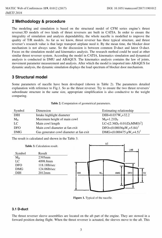
Some parameters of nacelle have been developed (shown in Table 2). The parameters detailed explanation with reference to Fig.1. So as the thrust reverser. Try to ensure the two thrust reversers’ subordinate structure in the same size, appropriate simplification is also conductive to the weight comparing.
Table 2. Computation of geometrical parameters�
Symbol Dimension Estimating relationship DIH Intake highlight diameter DIH=0.037Wa+32.2 MH Maximum height of main cowl MH=1.21DF LC Main cowl length LC=[2.36DF-0.01(DFMMO)2] DFO Main cowl diameter at fan exit DFO=(0.00036�Wa+5.84)2 DMG Gas generator cowl diameter at fan exit DMG=(0.000475��Wa+4.5)2
The result is calculated and shown in the Table 3.
Table 3. Calculation result��
Symbol Result MH 2395mm LC 4098.8mm DFO 118.18lb/sec DMG 124.06lb/sec DIH 2012mm
Figure 1. Typical of the nacelle.
3.1 D-duct
The thrust reverser sleeve assemblies are located on the aft part of the engine. They are stowed in a forward position during flight. When the thrust reverser is actuated, the sleeves move to the aft. This
DOI: 10.1051/, 01012 (2017) 71190119 10MATEC Web of Conferences matecconf/201IMETI 2016
12
3

�
moves the blocker doors to block the flow of air between the fan duct assembly and the thrust reverser sleeve assemblies [5], then exposes the cascade vanes. The air then flows out through the cascade vanes which direct the air forward to create reverse thrust [6].
On the basis of D-duct’s structure, main components of thrust reverser are fixed, on which the model is accomplished in CATIA(see Figs.2-3).
main components of each thrust reverser half� • Translating Sleeve • Inner Wall • 3 Hydraulic actuators and 2 sync shafts • 6 Cascades • 5 Blocker doors • 5 Blocker door drag links • 1 T/R opening actuator on pylon • Torque box • Fan duct inner wall • 3 Access doors • Upper and lower sliders and tracks
As the model shown, some shape parameters of thrust reverser(Table 4) and the stroke of translating sleeve under different working condition are measured in CATIA.
Table 4.���
�Leading particulars of T/R�
Height(above ground) 730mm Length 1553mm Maximum diameter 1240mm
�
Figure 2. Stowed.��
Figure 3. Deployed�
3.2 O-duct
The O-duct is similar to the “D” type thrust reverser on some level. It’s also consist of translating cowl, inner panel, actuator, blocker door mechanism, cascades, torque box, access doors and sliders. But with the structure changing of translating cowl from two parts into single one, more blocker doors are set up, which means more cascades and no more tension latches. Same as the blocker door mechanism, it cancels blocker door drag links, which contributes to decreasing aerodynamic drag. Above all, on the one hand structural simplification and different blocker door mechanism let every part of nacelle integrated better. On the other side, new technology is usually not perfect. The use of composite material and improved thrust reverser raise the T/R efficiency, but also left an uncertainty in terms of maintenance and economy.
All illustrated in Figs.4-5, from the comparison we see that O-duct has larger and more complete are of airflow than D-duct, which imply the air flow more smoothly through the bypass with less bifurcation. Due to it’s compact structure.
DOI: 10.1051/, 01012 (2017) 71190119 10MATEC Web of Conferences matecconf/201IMETI 2016
12
4

�
Figure 4. D-duct�
�
Figure 5. O-duct�
4 Simulation & result
4.1 DMU simulation
Digital Mock Up or DMU is a concept that allows the description of a product in 3D. The goal of doing DMU is to reduce time-to-market by identifying potential issues during the design, save product development costs by minimizing the number of physical prototypes needed to build, finally increase product quality. Figure 6 represent the work flow and key steps of DMU simulation.
�
Figure 6 . The DMU simulation flow chart.
4.2 Result
By simplifying the O-duct block door mechanism [4], establishing kinematic pairs, setting up the relationship with time, the DMU simulation is conducted in CATIA. In the simulation, both the unfolding time of two types thrust reverser is set for 1.5 second, and it holds for about 10 seconds at operating position. From the result of simulation, it’s clear to understand how block door works. For instance, each block door mechanism of O-duct is mainly consist of five parts except the block door itself (Figure 7). To unlock the sensor during the DMU simulation, CATIA outputs corresponding curve of motion parameter based on the position of measurement point and reference point. Figure 8 has it’s measurement point on the telescopic rod for the curve of liner speed.
DOI: 10.1051/, 01012 (2017) 71190119 10MATEC Web of Conferences matecconf/201IMETI 2016
12
5

�
�
Figure 7. O-duct block door mechanism� �
Figure 8. Liner speed of reference point�
5 Dynamical analysis
5.1 Reverse thrust
After getting the exit flow of cascade and bypass, the thrust of bypass can be calculated. The exit angle � is one of the key parameters, which determined by the geometry of cascade.
� ! �"#!$%&' ( )* (
" !$+&' , & ! �� -.
/01- reverse thrust 201- when thrust reverser works, the gas flow through T/R 3'- speed of exit gas flow 4- landing speed 5- exit angle 261- the gas flow through engine 7- gravity acceleration
(2)
It’s defined that the reverser thrust counts about 30 percent of maximum thrust, the pressure on block door is 0.0035Mpa.
5.2 Dynamical simulation
To have a convenient and accurate simulating method, simplified the model of block door mechanism is needed. Holding the necessary features, then transfer the CATIA data into ABAQUS for meshing.
�
Figure 9. O-duct’s block door.�
�
Figure 10. D -duct’s block door.�
DOI: 10.1051/, 01012 (2017) 71190119 10MATEC Web of Conferences matecconf/201IMETI 2016
12
6

The material properties for structural analysis are aluminium alloy with a Young’s modulus of 71Gpa and a density of 2800kg/m2. The pressure is applied to the block door using the calculation results. Assuming that two kinds of block door have same opening time and reverser angle, and in the similar condition of airflow, ignore the influence of cascades [8]. Figure 9-10 shows a contour plot representing the deformations. The maximum displacement both on the block door.
Figure 11-12 show a contour plot representing the stress, the maximum stress occurs on joints which tie the block door with translating sleeve. The maximum stress value of O-duct is 91Mpa, which almost twice the value of D-duct,57.1 Mpa.
�
Figure 11. Stress contours of O-duct’s block door.�
�
Figure 12.�Stress contours of O-duct’s block door.�
6 Conclusions
This paper carried out a contrastive study of two types of thrust reverser, through the kinematic and dynamic simulation of models which built in CATIA. Based on which, the structure, movement and stress analysis is conducted. The finally consequence imply that if leaves out the pylon, for the structure varies from each other, D-duct is heavier with sorts of tension latches and connectors. In the process of DMU simulation, it’s evident that O-duct requires more time to work at full open position, and some trouble may happen with it’s complicated block door mechanism. As the result of dynamic simulation, maximum displacement point is located in the edge of block door, while the stress concentrate on the links between translating sleeve and the block door mechanism.
References
1. Q. Xuhao, W. Zhanxue, L. Zengwen, Z. Xiaobo, and S. Jingwei, Machinery Design & Manufacture. J., 11 (2013)
2. J.A. Yetter, Why Do Airlines Want and Use Thrust Reversers[R], NASA.TM-10 (1995) 3. S. Béchu, N. Gascon, S. Roche, M. Prioul, L. Albarede, P. Lasgorceix, and M. Dudeck, AIAA,
AIAA-2000-3524 (2000) 4. Z. Shaojun, W. Hanping, H. Jiangjun, S. Libing, and J.Sichuan. Ordnance, 3 (2015) 5. D.J. Strash, J.M. Summa, J.H. Frank, and R. Standish, J. Propul Power, 16 (2000) 6. Z. Yunhao, Eriqitai, International Coference on Industrial Control and Electronics Engineering
(2012) 7. E.G. Rulz, T. Mahmod, V. Sethi, and P. Pilidis, Proceedings of ASME Turbo Expo, GT2012-68810
(2012) 8. Z. Guodong and W. Qiang, J. Aerosp Power, 27 (2012)
DOI: 10.1051/, 01012 (2017) 71190119 10MATEC Web of Conferences matecconf/201IMETI 2016
12
7


![Thrust Reversers for a Separate Exhaust High Bypass Ratio … · 2011-06-22 · performance analysis along with the Gas Turbine Performance Software, ‘GasTurb 10’ [1]. The CUTEA](https://img.pdfslide.us/doc/110x75/5e6adb28e2ac82263e5b5094/thrust-reversers-for-a-separate-exhaust-high-bypass-ratio-2011-06-22-performance.jpg)