Embed Size (px)
Citation preview

THESIS ON POWER INGINEERING, ELECTRICAL ENGINEERING, MINING ENGINEERING
Analysis and Development of the PLC Control System with the Distributed I/Os
OLGA RUBAN

Department of Electrical Drives and Power Electronics Faculty of Power Engineering
TALLINN UNIVERSITY OF TECHNOLOGY
Dissertation was accepted for the defence of the degree of Doctor of Science in Natural and Exact Sciences at 10: 00 on December 19, 2008 in Tallinn University of Technology, Ehitajate tee, 5, A.7 room 430 Supervisor: Professor Juhan Laugis, Dr. Sc., Department of Electrical Drives and Power Electronics, Faculty of Power Engineering, Tallinn University of Technology Opponents: Professor Toomas Rang, Dr Sc., Department of Electronics, Faculty of Information Technology, Tallinn University of Technology Professor Anatoly Levchenkov, Dr Sc., Faculty of Power and Electrical Engineering, Institute of Industrial Electronics and Electrical Engineering, Riga Technical University Johannes Presmann, PhD, Senior Consultant, Area of Electricity Defence of Thesis: December 19, 2008
Declaration: Hereby I declare that this doctoral thesis, my original investigation and achievement, submitted for the doctoral degree at Tallinn University of Technology, has not been submitted for any academic degree. Olga Ruban Copyright: Olga Ruban, 2008 ISSN ISBN

ENERGEETIKA, ELEKTROTEHNIKA, MÄENDUS
Hajutatud sisenditega/väljunditega programmeeritavate kontrollerite
juhtimissüsteemi analüüs ja arendamine
OLGA RUBAN

4
TABLE OF CONTENT INTRODUCTION ......................................................................................... 6 ABBREVIATIONS ..................................................................................... 13 TERMS ........................................................................................................ 14 SYMBOLS................................................................................................... 17 1 STATE-OF-THE-ART OF THE PLC FUNCTIONS IN CONTROL SYSTEMS.................................................................................................... 18 1.1 PLC overview ................................................................................................... 18 1.2 Input/output modules ........................................................................................ 24
1.2.1 PLC input signals ........................................................................ 25 1.2.2 PLC output signals ...................................................................... 27
1.3 PLC safety - Overview of basic aspects of protection ...................................... 28 1.3.1 System diagnostics ...................................................................... 28 1.3.2 Safety of electronic control equipment. ...................................... 28 1.3.3 Splitting the group into safety-relevant and non-safety-relevant areas...................................................................................................... 29 1.3.4 Redundancy................................................................................. 29
1.4 Electromagnetic compatibility .......................................................................... 31 1.5 PLC networks.................................................................................................... 33 1.6 Survey in Estonia .............................................................................................. 36 1.7 Conclusions of Chapter 1.................................................................................. 37 2 STRUCTURAL SYNTHESIS OF PLC CONTROL WITH THE DISTRIBUTED I/O ..................................................................................... 39 2.1 Configuring distributed I/Os with PROFIBUS DP........................................... 39 2.2 Development of the control system with S7 300, ET200M, Ex I/O modules... 40
2.2.1 DP master control of the distributed I/O..................................... 40 2.2.2 PROFIBUS configuration ........................................................... 41 2.2.3 Addresses in the DP master system ............................................ 42 2.2.4 Distributed modular I/O systems ................................................ 43 2.2.5 Transfer memory with intelligent DP slaves............................... 43
2.3 PROFIBUS PA ................................................................................................. 44 2.3.1 Interfacing ................................................................................... 44 2.3.2 DP/PA coupler ............................................................................ 45 2.3.3 Defining cable lengths. ............................................................... 46
2.4 PA intelligent device analysis........................................................................... 46 2.5 Configuring the network ................................................................................... 47 2.6 Designing a PLC system................................................................................... 48 2.7 Installation of PLC............................................................................................ 49 2.8 Equipotential bonding of explosion protected systems..................................... 50 2.9 Conclusions of Chapter 2.................................................................................. 50 3 DEVELOPMENT OF THE DESIGN METHOD FOR AN EXPLOSION PROTECTED CONTROL SYSTEM.......................................................... 52

5
3.1 Control system hardware structure ................................................................... 52 3. 2 Configuration of the control project according to demands............................. 53
3.2.1 Connection of sensor controls and actuators to a PLC ............... 53 3.2.2 PROFIBUS DP for INTELLI+ ................................................... 55 3.2.3 Configuration software for all process devices........................... 59
3.3 Measurement..................................................................................................... 61 3. 3.1 PROFIBUS test project configuration ....................................... 62 3.3.2 Pressure measurement................................................................. 63 3.3.3. Level measurement .................................................................... 64 3.3.4 Density measurement and calculation......................................... 68 3.3.5. Temperature measurement ......................................................... 69
3.4 Redundancy of the developed system............................................................... 70 3.5 Conclusions of Chapter 3.................................................................................. 72 4 SOFTWARE DEVELOPMENT AND EXPERIMENTAL RESEARCH OF THE CONTOL SYSTEM...................................................................... 73 4.1 Description software of the developed project.................................................. 73 4.2 Control program................................................................................................ 75
4.2.1 Programming Consideration. Basic Elements of a Program....... 75 4.2.2 Control program configuration ................................................... 76 4.2.3 Data handling from ten storage tanks (FC1) ............................... 78 4.2.4 Fault signal displayed with light and sound signaling (FC2)...... 81 4.2.5 Actuator control (FC3)................................................................ 83
4.3 System diagnostics............................................................................................ 84 4.3.1 Diagnostic interrupt blocks ......................................................... 85 4.3.2 Diagnostics DP/DP by means of the program ............................ 86
4.4 Conclusions of Chapter 4.................................................................................. 87 5 SUMMARY.............................................................................................. 88 6 REFERENCES..........................................................................................90 ABSTRACT................................................................................................. 94 LÜHIKOKKUVÕTE (ANNOTATSIOON)................................................ 95 PUBLICATIONS......................................................................................... 96 LISA/APPENDIX 1..................................................................................... 98 APPENDIX 2............................................................................................. 100 APPENDIX 3............................................................................................. 124 ELULOOKIRJELDUS .............................................................................. 124 CURRICULUM VITAE ............................................................................ 126

6
INTRODUCTION Background Control systems are an integral part of modern society. Design, testing and optimization of automatic control systems with the programmable logic controllers (PLC) have become extraordinarily important [BOL03]. The objectives of automation engineering include the development, analysis, synthesis and testing of technical systems designed to effect the optimum performance of technical and manufacturing processes without continuous human involvement. The degree of automation implemented is determined by the extent to which the process or the manufacturing method is actually performed automatically by automation equipment and a system. The primary objectives of productivity, flexibility, safety and environmental protection in technical and manufacturing processes have led to the ever growing need to increase the degree of automation. Consequently, automation technology is in the middle of rapid development which can be characterized by the following four features:
• transition from analog to digital and hybrid automation equipment through the integration of computer-supported systems and processes;
• application of control methods for the automatic control of technical systems using language-based variables without complex mathematical models;
• optimization of the human-to-process communication chain by integrating communications, information processing and sensor-actuator systems;
• application of complex and hierarchically configured automation structures and implementation of adaptive and intelligent systems.
Basic system components of automatic control technology are characterized by such functions as measurement, information processing and automatic control. Solution of control problems involves the following: principles of efficiency, speed and accuracy to the extent that they apply to the particular task. Automatic control technology also employs findings of the respective mathematical, scientific and technical disciplines to solve problems [DOR02]. Automatic control systems enable one to operate the processes in a safe and profitable manner. Control systems achieve this "safe and profitable" objective by continually measuring process variables. The overriding motivation for automatic control is safety of the people, the environment and equipment. Plant-level control objectives motivated by profit include meeting final product specifications, minimizing waste production, minimizing the environmental impact, minimizing energy use, and maximizing the overall production rate.

7
Introduction of the automated control systems by technological processes is a perspective of energy safety direction [BAT93]. Economic benefit of control systems (over 30 % of the economy of power resources) is reached due to the exact control of parameters of a technological process, monitoring of the condition of the process equipment and reduction of the reaction time of the personnel by emergency and pre-emergency events. Process performance means optimizing the process, the equipment, and the controls. Nowadays, advanced control is synonymous with the implementation of computer-based technologies. Programmable logic controllers (PLC) are considered today as a principal item of automation. With these controllers, most diverse tasks of automation can be implemented depending on the definition of the problem. Systems traditionally associated with process control are being used in discrete applications. The control device is the major interface with the plant, from single-loop systems to distributed-control systems. It allows for а plant to find major control problems, diagnose what is causing the problem and get the whole plant lined out at a specification. Sometimes the problem is in the process, in the basic design, or in equipment malfunctioning. But it could be in the control system, in the basic strategy, or in hardware malfunctioning. Modern control systems require numerous loops to be controlled at the same time – pressure, level, temperature, for example [CHI96]. Advantages of PLCs are that these systems can control numerous loops. Controllers are a component part of automation systems whose main tasks are those of process stabilization. They are used to bring about maintaining specific process states (operation mode) automatically, eliminating the effects of interference on the process sequence, preventing unwanted coupling of the components of the processes in the technical process. The function of the PLC is to control, monitor, and integrate everything in this process, and the computer allows the PLC and process interface to the outside world - operators, other processes, and higher level systems. The control systems consist of different units and involve complex problems. Controllers always have an ability to receive input, to perform a mathematical function with the input, and to produce an output signal corresponding to the manipulated variable. In an intelligent society, individuals communicate with each other, organize themselves and form networks. This paradigm is also utilized in modern

8
technology and confers individual objects equipped with sensors, actuators and software a certain level of intelligence and identity. Through modern communications technology, single components are melt into an integrated network system. Remote operations, adverse environmental conditions, extreme climates, hazardous space – these are but a few of the demanding challenges that typify oil shale exploration and production. They demand product requirements that include extreme ruggedness, maximum availability and compact, modular designs. These requirements extend to the control of complex oil shale treatment processes using various technologies suited for measuring an array of different appropriate parameters. All the parts in a plant must work as an integrated whole. This requires open, integrated communication linking automation throughout the company. This study helps to avoid the use of isolated applications in automation and in information technology through
• a seamless flow of information from the sensor/actuator level to the high management level;
• availability of information in any place; • fast data exchange between plant sections; • consistent configuration and efficient diagnostics; • integrated security functions that prevent unauthorized access; • fail-safe communication and standard communication using the same
cable. Such a configuration makes use of intelligent devices at the local level that interface with one another over networks. Openness and flexibility enable one to easily link different systems and implement expansions. This does not only reduce the number of interfaces, but it also ensures maximum data transparency across all levels – from the field, through the production level to the management level. PROFIBUS, the international standard for the field level, and Industrial Ethernet, the international standard for area networking, are used for these purposes.
9
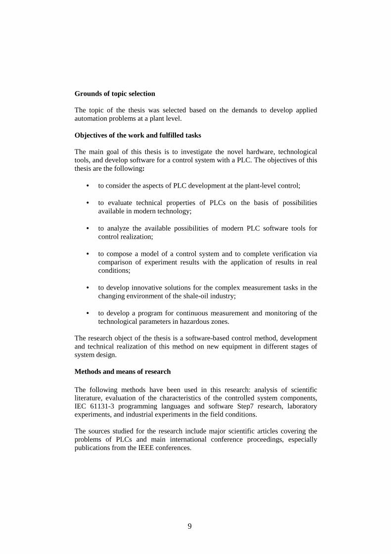
Grounds of topic selection The topic of the thesis was selected based on the demands to develop applied automation problems at a plant level. Objectives of the work and fulfilled tasks The main goal of this thesis is to investigate the novel hardware, technological tools, and develop software for a control system with a PLC. The objectives of this thesis are the following:
• to consider the aspects of PLC development at the plant-level control; • to evaluate technical properties of PLCs on the basis of possibilities
available in modern technology; • to analyze the available possibilities of modern PLC software tools for
control realization;
• to compose a model of a control system and to complete verification via comparison of experiment results with the application of results in real conditions;
• to develop innovative solutions for the complex measurement tasks in the
changing environment of the shale-oil industry;
• to develop a program for continuous measurement and monitoring of the technological parameters in hazardous zones.
The research object of the thesis is a software-based control method, development and technical realization of this method on new equipment in different stages of system design. Methods and means of research The following methods have been used in this research: analysis of scientific literature, evaluation of the characteristics of the controlled system components, IEC 61131-3 programming languages and software Step7 research, laboratory experiments, and industrial experiments in the field conditions.
The sources studied for the research include major scientific articles covering the problems of PLCs and main international conference proceedings, especially publications from the IEEE conferences.

10
To solve theoretical and technical problems, such models and packages as S7-300 PLC, Simatic PDM tools were employed. The IEC 61131-3 programming languages and PLC programming as well as debugging tools were used in the software development process. IEC 61131-3 PLC languages have been used to model the control logics, and mathematical tools to calculate the control system parameters. The high level programming languages allowed more advanced control strategies in PLC based control applications to be implemented. The experiments with control principles and program tests were carried out in the Laboratory of Automation at Virumaa College (Appendix 2) and at Viru Chemistry Group Ltd. Source information The studies and design took into account the standards, scientific publications (references), existing documentation, and research reports about similar systems. New and improved product development also requires information from personal practice and information about the drawbacks of existing products. Information about system drawbacks was acquired from users of these products via unofficial interviews. Additional information was derived from the company support and working experience in the format of a retraining program at Viru Chemistry Group Ltd. Sources of information used in the control system design: 1. technical specifications and data about new systems including technical documentation and commercial information; 2. technical specifications and documentation about competitive systems; 3. information collected via visits and work in the company as well as unofficial interviews; 4. information from Siemens company support. Sources of information used in the software development: 1. test and measurement results; 2. manuals of new software tools; 3. datasheets, manuals and application notes of electronic components; 4. analyzed and specified user opinions, requirements and practical needs. The novelty of the present research lies in the following. The author has developed a generalized structure for the modeling of real control system, including its configuration. The model was used to implement control functions and new software-based solutions. For this model development, an experimental study was carried out in the laboratory. Experimental testing of operation and malfunctioning modes is not possible in the real conditions because of

11
high risks and high costs of experiments. The control algorithms for a DGO storage tank park control system have been developed.
An analysis of operation modes was made. This is necessary for the development of control functions and protection algorithms, including the analysis of faults in different operation modes (for the application of diagnostic methods). Finally, all the research goals of the thesis set in the introduction have been completed successfully. Experiments were carried out at Viru Chemistry Group Ltd by the author together with the project team. As a result, proper control methods and preliminary software design were selected and developed. The performance is illustrated on a field test application for the DGO storage tank park control system.
Experiments, software development and improvement of documentation are being continued up to now.
It is a pleasure to thank my supervisor, professor Juhan Laugis for his valuable advice and inspiration. His efforts have made a significant contribution to this work. I would like to thank him for his optimistic support during the whole of my educational process. I would also like to thank my colleagues at Viru Chemistry Group Ltd, especially PhD V. Sychev, who helped to solve practical problems encountered in the application of results in real conditions.
My special thanks are due to Mr Ruslan Hamzin and Mr Ats Alupere for their financial support to my research. Outline of the thesis The introduction covers the goal of the thesis. The purpose and research problems are formulated, scientific novelty as well as the practical importance and forms of work approbation are provided. Chapter 1 describes recent trends in the field of PLC application in control systems, including configurations of different PLC systems as perspective development and application areas. Chapter 2 provides the hardware configuration and the PLC functions possibility to implement the synthesis and the design of a control system. Chapter 3 discusses the PLC commissioning conditions for different types of the field devices of the control system.

12
Chapter 4 shows the software developed by the author for the DGO storage tank park control system.
13
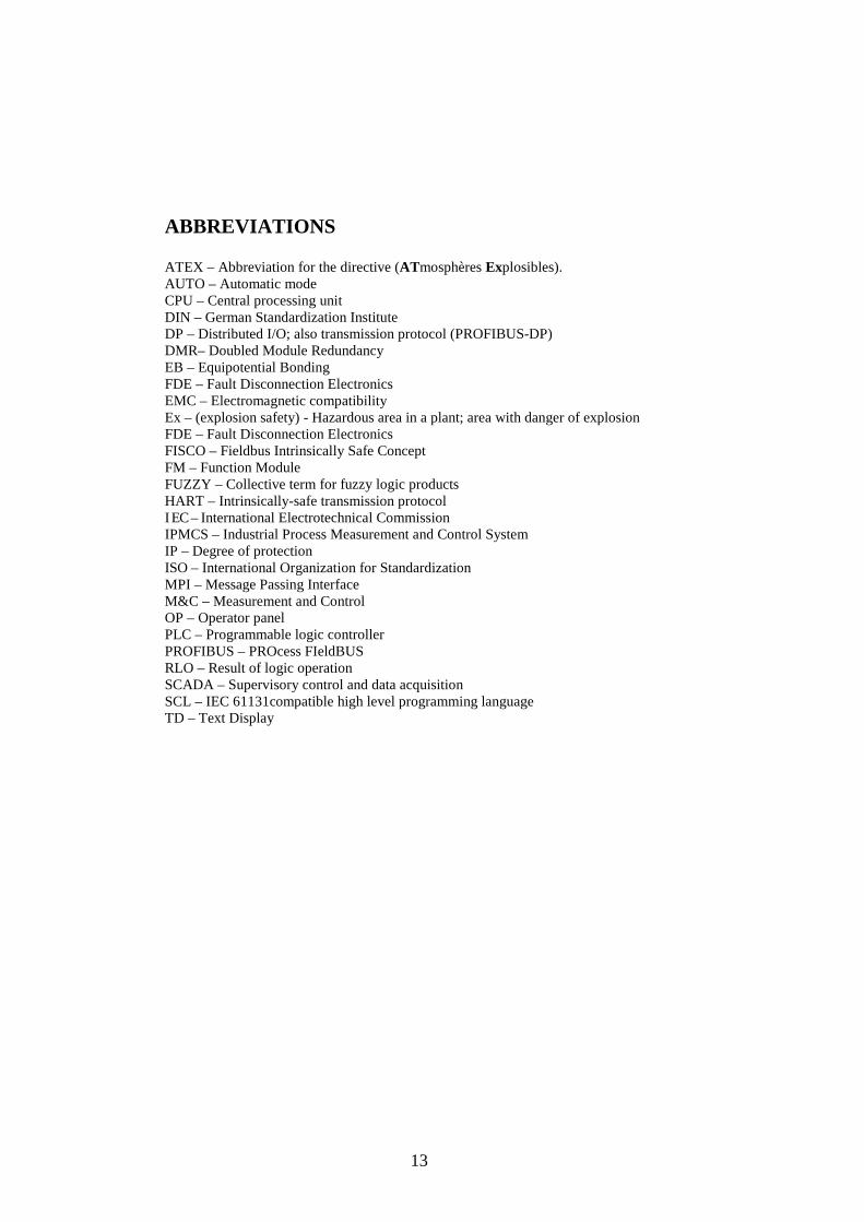
ABBREVIATIONS ATEX – Abbreviation for the directive (ATmosphères Explosibles). AUTO – Automatic mode CPU – Central processing unit DIN – German Standardization Institute DP – Distributed I/O; also transmission protocol (PROFIBUS-DP) DMR– Doubled Module Redundancy EB – Equipotential Bonding FDE – Fault Disconnection Electronics EMC – Electromagnetic compatibility Ex – (explosion safety) - Hazardous area in a plant; area with danger of explosion FDE – Fault Disconnection Electronics FISCO – Fieldbus Intrinsically Safe Concept FM – Function Module FUZZY – Collective term for fuzzy logic products HART – Intrinsically-safe transmission protocol I EC – International Electrotechnical Commission IPMCS – Industrial Process Measurement and Control System IP – Degree of protection ISO – International Organization for Standardization MPI – Message Passing Interface M&C – Measurement and Control OP – Operator panel PLC – Programmable logic controller PROFIBUS – PROcess FIeldBUS RLO – Result of logic operation SCADA – Supervisory control and data acquisition SCL – IEC 61131compatible high level programming language TD – Text Display

14
TERMS ADC – Analog-Digital Converter Analog module Analog modules convert analog process variables (for example, temperature) into digital values that can be processed in the CPU or they convert digital values into analog manipulated variables. ATEX – Abbreviation for the directive. According to the directive, equipment is divided into 2 categories of protection, that correspond to the Zones where it may be used. Behind the category classification follows the type of protection. Backup battery The backup battery ensures that the user program in the CPU is not lost in the event of a power failure and that defined data areas, bit memory, timers, and counters are also retained. Building ground The connection between data processing equipment and ground, whereby no unacceptable functional interference to data processing equipment is caused by external effects, such as interference caused by power systems. The connection must be in the form of a low-noise ground. Cold restart Restart of an automation system and its user program after all dynamic data (tags of the I/O image, internal registers, timers, counters etc. and the corresponding program elements) were reset to default. A cold start may be triggered automatically (for example, due to power failure, loss of dynamic data in memory). Communication Communication is the exchange of data between programmable modules when the operating system handles almost all communication functions. Communication utility A communication utility specifies how the communication stations are to exchange data and how' these data are to be treated. Connection A connection defines the relationship between two communication stations. It represents the logical allocation of two stations for execution of a certain communication utility. It also contains special characteristics such as the type of connection (dynamic or static) and how the connection is established. Communication functions The communication functions are the user program's interface to the communication utility. Configuration The configuration is the selection and putting together of the individual components of a programmable logic controller (PLC). CPU Central processing unit of the programmable controller with processor, arithmetic unit, memory, operating system, and programming device interface. Cycle time The time a CPU requires to execute the user program.

15
DP/PA coupler, DP/PA link are the network components for linking PROFIBUS DP and PROFIBUS PA to convert the transmission rates of PROFIBUS DP to the transmission rate of PROFIBUS PA. EMC Electromagnetic compatibility Electromagnetic compatibility is understood to mean the capability of electrical apparatus to operate without faults in a given environment, without affecting that environment in an unacceptable manner. Error display Error display is one of the possible responses of the operating system to a run-time error. The other possible responses include: error response in the user program, STOP mode of the CPU. FORCE Function which can be used to assign fixed values to specific tags in a user program or CPU (also: I/Os), so that the user program is not able to change or overwrite these values. The function allows users to set defined tag values in the user program for use in specific situations and to test the programmable functions. Function(FC) According to IEC 61131-3, a function is a code block that does not contains any static data. Temporary tags of functions are stored in the local data stack and will be lost after the FC was executed. Functions are therefore suitable for storing data in shared DBs. Because FCs are not assigned a memory, you always need to specify their actual parameters. Function Block (FB) According to IEC 61131-3, a function block (FB) is a code block that contains static data. It is assigned an instance DB as memory. Ground The conductive mass of the ground whose potential can be assumed to be zero at any point. In the vicinity of ground electrodes, the ground may have a potential other than zero. The term “reference ground” is often used in this situation. To ground means connecting an electrically conductive part via a grounding system to ground (one or more electrically conductive parts that have good contact with the soil). Network, subnet A network is a group of devices joined together for the purpose of communication. Operating State The programmable controllers recognize the following operating states: STOP, STARTUP, RUN. Organization Block (OB) Organization blocks form the interface between the operating system of the PLC CPU and the user program. The sequence in which the user program should be processed is laid down in the organization blocks. PROFIBUS (PROcess FIeld BUS) is a standard documented in volume 2 of EN 50170 and covers the networking of field devices. PROFIBUS DP The PROFIBUS DP (Distributed Peripherals) offers a standardized interface for the ex-change of mainly binary process data over RS 485 between an "interface module" installed in the (centralized) programmable logic controller and the field devices. The maximum data transfer rate on the PROFIBUS DP is 12 Mbit/s. PROFIBUS DP is standard based on IEC 61158/EN 50170.

16
PROFIBUS DP modules Digital, analog and intelligent modules, as well as a wide range of field devices to EN 50170, Part 3, such as drives or valve modules are moved to the local process by the PLC. The modules and field devices are interconnected with the PLC via PROFIBUS DP field bus and are addressed in the same way as local I/O. PROFIBUS PA The PROFIBUS PA (Process Automation) is a communication network for the process in-dustry and can be used in intrinsically safe areas, such as hazardous areas of Zone 1. PROFIBUS DP (V0), PROFIBUS DPV1 PROFIBUS DP (V0) runs cyclic communication when PROFIBUS DPV1 runs in addition acyclic messages. Priority classes The PLC CPU operating system provides up to 26 priority classes (or “program execution levels”) which are assigned different OBs. These classes determine which OB can interrupt other OBs. Several OBs belonging to the same priority class do not interrupt each other, and are executed in sequential order. Programming Device (PG) A personal computer with a special compact design, suitable for industrial conditions. PROFINET is the Industrial Ethernet Standard devised by PROFIBUS International for "Ethernet on the plant floor". Redundancy is the duplication of critical components of a the system, usually in the case of a backup or fail-safe.system with the intention of increasing reliability of of the system, usually in the case of a backup or fail-safe. SIMATIC PDM is a software package for designing, parameterizing, commissioning, diagnosing and maintaining the process devices. System is a separate arrangement of components, which are all interrelated to each other (DIN19226). TÜV - German Institute for Technological Surveillance
17
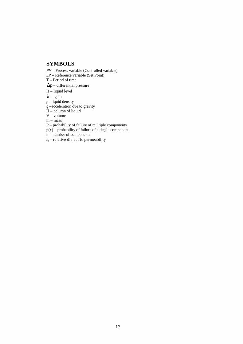
SYMBOLS PV – Process variable (Controlled variable) SP – Reference variable (Set Point) T – Period of time
p∆ – differential pressure
Н – liquid level k – gain ρ –liquid density g –acceleration due to gravity H – column of liquid V – volume m – mass P – probability of failure of multiple components p(x) – probability of failure of a single component n – number of components εr – relative dielectric permeability

18
1 STATE-OF-THE-ART OF THE PLC FUNCTIONS IN CONTROL SYSTEMS
1.1 PLC overview
Programmable logic controllers are considered today as a principal item of automation [PAR03]. With these controllers, most diverse tasks of automation can be implemented depending on the definition of the problem (Fig. 1.1). Programmable logic controllers have been around forever (in technology years). Their proven reliability in harsh environments and design to handle many inputs and outputs has made them the foundation of many factory automated systems.
Fig. 1.1 PLC is an item of automation. Controllers - in the sense of automatic control systems - are functional elements which act on a physical variable by means of an actuator depending on an analyzed process variable (measured using a sensor) in a closed, analog circuit with exact mathematical definitions. This is shown in Fig. 1.2.
Controller
AlgorithmSensor Actuator
Process
Fig. 1.2 Basic flow of signals in a controller.
476 companies supply Programmable Logic Controllers (PLCs). PLCs are the control hubs for a wide variety of automated systems and processes. They contain

19
multiple inputs and outputs that use transistors and other circuitry to simulate switches and relays to the control equipment. PLC system specifications to be considered include scan time, number of instructions, data memory, and program memory. They are programmable via software interfaced via standard computer interfaces and proprietary languages and network options.
PLCs come in a variety of sizes: large, medium, small, micro, and nano. PLC CPUs have different characteristics.
Omron’s SRM1 has all of its processing power and control in the master unit, which supports up to 256 networked I/O (128 inputs/128 outputs) across a twisted pair network up to 500 meters away. The PLC’s execution time for basic instructions is 0.97 microseconds. The PLC’s execution time is measured according to IEC 61131[IEC 61131]. User’s program should be equal to 1К with the programming language IL IEC 61131-3.
S7-200 mini PLC provides 24 KB program memory capacity and 10 KB data memory, 16-bit timers, 12-bit ADC with signal conversion with 25 µs, an SPI (Serial Peripheral Interface) and a SCI (UART), time interrupts between 1 and 255 ms, with a resolution of 1 ms. Bit processing speed is 0.22µs. It has over 200 instructions, including floating-point math, PID, for/next loops, subroutines, and sequence control for both simple discrete control and analogue control. Combined with the device’s 20-KHz high-speed counters, interrupts, and 100 kHz pulse outputs, the S7-200 series provides real-time control with Boolean processing speeds of 0.375 microseconds per instruction. Unitronics Vision 120 U2A, Unitronics M90-19-B1A have 10 digital inputs, 1 analog input, 6 relay outputs, RS232, response time 0 to 1–5 ms 1 to 0–10 ms, resolution 16 bit, 1 analog input resolution for 0 - 20 mA is 10 bit (1024 units), for 4–20 mA are from 204 to 1024 (820 units) [REM08]. Mitsubishi PLC family has RAM 8 – 16 K, EPROM 8 – 16 K, EEPROM 4 – 16 K [MIT01]. S7-400 contains a work memory of 512 KB for the code; a load memory 256 KB; integrated Expandable FEPROM with a memory card (FLASH) 1 MB up to 64 MB; Expandable RAM with a memory card (RAM) 256 KB up to 64 MB; Processing times for Bit instructions 75 ns, Word instructions 75 ns, Floating-point math 225 ns [BERG06]. Programmable logic controllers use the software programming languages for control. The IEC 61131-3 programming environment provides support for five languages specified by the global standard: Sequential Function Chart, Function

20
Block Diagram, Ladder Diagram, Structured Text, and Instruction List. This allows for multi-vendor compatibility and multi-language programming. SFC is a graphical language that provides coordination of program sequences, supporting alternative sequence selections and parallel sequences. FBD uses a broad function library to build complex procedures in a graphical format. Standard math and logic functions may be coordinated with customizable communication and interface functions. LD is a graphic language for discrete control and interlocking logic. It is completely compatible with FBD for discrete function control. ST is a text language used for complex mathematical procedures and calculations less well suited to graphical languages. IL is a low-level language similar to an assembly code. It is used in relatively simple logic instructions. Relay Ladder Logic, or ladder diagrams, are today’s most widespread programming languages for control [PAR03]. Flow Chart is a graphical language that describes sequential operations in a controller sequence or application. It is used to build modular, reusable function libraries. The standardization of high level programming languages for PLCs allows implementing more advanced control strategies in PLC-based control applications. C++ is a high level programming language suited to handle the most complex computation, sequential, and data logging tasks. It is typically developed and debugged on a PC-soft PLC. IEC 61499 is a standard of software development in the area of Industrial Process Measurement and Control System (IPMCS). This standard simplifies the development of distributed IPMCS applications through inclusion of re-usability, encapsulation and modularity. Due to its close resemblance with the Object-Oriented paradigm, IEC 61499 also defines a way to integrate modeling techniques into the development process of the distributed IPMCS applications. Programmable logic controllers I/O channel specifications include the total number of points, the number of inputs and outputs, the ability to expand, and the maximum number of channels. The number of points is the sum of the inputs and the outputs. PLCs may be specified by any possible combination of these values. Expandable units may be stacked or linked together to increase the total control capacity. Maximum number of channels refers to the maximum total number of input and output channels in an expanded system.
21
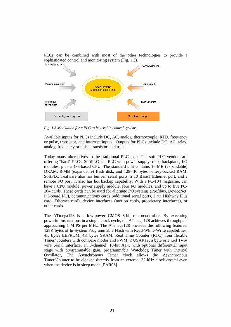
PLCs can be combined with most of the other technologies to provide a sophisticated control and monitoring system (Fig. 1.3).
Fig. 1.3 Motivation for a PLC to be used in control systems. Available inputs for PLCs include DC, AC, analog, thermocouple, RTD, frequency or pulse, transistor, and interrupt inputs. Outputs for PLCs include DC, AC, relay, analog, frequency or pulse, transistor, and triac. Today many alternatives to the traditional PLC exist. The soft PLC vendors are offering “hard” PLCs. SoftPLC is a PLC with power supply, rack, backplane, I/O modules, plus a 486-based CPU. The standard unit contains 16-MB (expandable) DRAM, 8-MB (expandable) flash disk, and 128-4K bytes battery-backed RAM. SoftPLC Tealware also has built-in serial ports, a 10 BaseT Ethernet port, and a remote I/O port. It also has hot backup capability. With a PC-104 magazine, can have a CPU module, power supply module, four I/O modules, and up to five PC-104 cards. These cards can be used for alternate I/O systems (Profibus, DeviceNet, PC-board I/O), communications cards (additional serial ports, Data Highway Plus card, Ethernet card), device interfaces (motion cards, proprietary interfaces), or other cards. The ATmega128 is a low-power CMOS 8-bit microcontroller. By executing powerful instructions in a single clock cycle, the ATmega128 achieves throughputs approaching 1 MIPS per MHz. The ATmega128 provides the following features: 128K bytes of In-System Programmable Flash with Read-While-Write capabilities, 4K bytes EEPROM, 4K bytes SRAM, Real Time Counter (RTC), four flexible Timer/Counters with compare modes and PWM, 2 USARTs, a byte oriented Two-wire Serial Interface, an 8-channel, 10-bit ADC with optional differential input stage with programmable gain, programmable Watchdog Timer with Internal Oscillator, The Asynchronous Timer clock allows the Asynchronous Timer/Counter to be clocked directly from an external 32 kHz clock crystal even when the device is in sleep mode [PAR03].

22
Unlike PC-based control systems that first boot an operating system, then the application for control, both of these SoftPLC systems are PLCs with a PLC operating system. Upon bootup, SoftPLC embeds a 32-bit, real-time, multi-tasking kernel into RAM, creating a hard real-time deterministic controller. According to the company, SoftPLC’s instruction execution times on a 486-based system are generally 2 to 10 times faster than conventional PLCs. On Pentium systems, scan times are 50 to 100 times faster than a conventional PLC. Rexroth ships all of its controllers with 2 MB of RAM (4 MB optional) for user data. This supports PLC programs equal to about 300,000 instructions.
PLC power options, mounting options and environmental operating conditions are all also important to be applied in control systems (Fig. 1.4).
Fig. 1.4 PLC with a number of computer interface options. Some programmable logic controllers are equipped to solve problems involving mathematical functions such as sine, cosine, tangent, xy, y root of x, e sub x, natural and common logarithms required for the control of many processes. A sophisticated programmable logic controller is capable of performing these calculations on many different portions of a process simultaneously. Such calculations are often required for energy management, process control, process modeling, and real-time error correction. The ability to handle analog signals along with arithmetic and other complex calculations has made programmable logic controllers suitable for process control. In support of those functions, some programmable logic controllers now have the ability to store recipes for batch processing, reducing the need for manual inputs.

23
In practice, controllers not only consist of a mathematical definition (algorithm), they also contain a number of control functions for operation, monitoring, safety functions and linking possibilities in a controller network at sampling rates from 20 to 2,000 Hz [BER02].
Fig. 1.5 PLC place in the industrial environment.
A modern programmable logic controller can also pass information back to the operator. It can print out its own ladder diagram for record, review, or change, or it can provide status or progress reports routinely or on request. A programmable logic controller can also display messages to summarize data or guide the operator. Data-analysis programs are becoming increasingly common [JEE05]. Usually each programmable logic controller is assigned a tag or a number. The programmable logic controller initiates changes to data within the computer database, which initiate other control tasks. The programmable logic controller also can track down external faults. This capability is useful because the machine and externally mounted control elements such as limit switches, solenoids, sensors, transducers, remote pushbuttons and selector switches are usually much less reliable, and more often a cause of machine downtime than the PLC (Fig. 1.5). Each part of a controller has a number of different, optional functions whose implementation or activation significantly influences the controller response and also defines the name of the many different types of the controller.
24
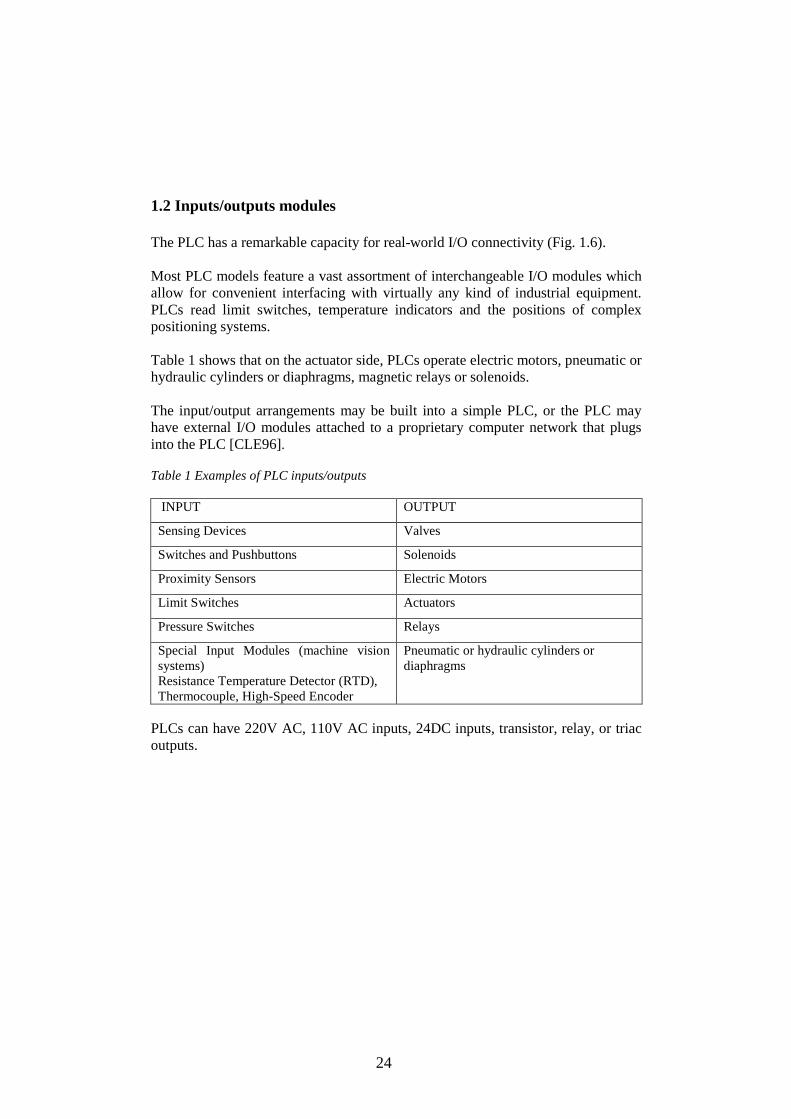
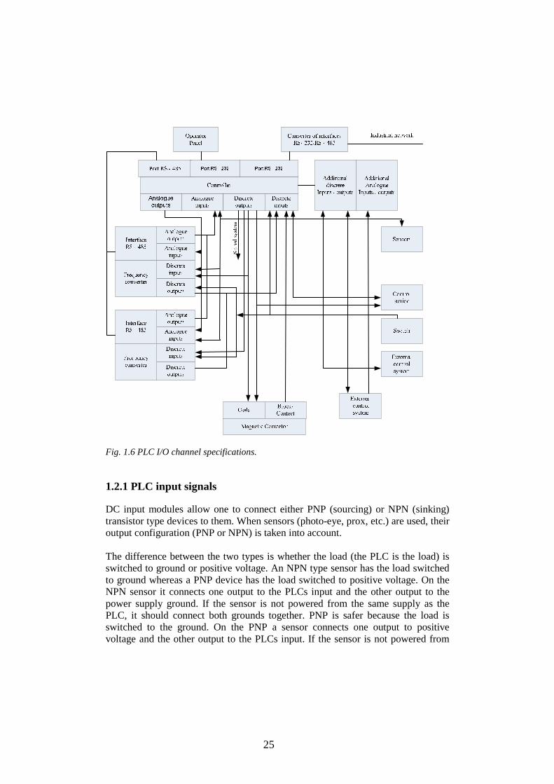
1.2 Inputs/outputs modules The PLC has a remarkable capacity for real-world I/O connectivity (Fig. 1.6). Most PLC models feature a vast assortment of interchangeable I/O modules which allow for convenient interfacing with virtually any kind of industrial equipment. PLCs read limit switches, temperature indicators and the positions of complex positioning systems. Table 1 shows that on the actuator side, PLCs operate electric motors, pneumatic or hydraulic cylinders or diaphragms, magnetic relays or solenoids. The input/output arrangements may be built into a simple PLC, or the PLC may have external I/O modules attached to a proprietary computer network that plugs into the PLC [CLE96]. Table 1 Examples of PLC inputs/outputs INPUT OUTPUT
Sensing Devices Valves
Switches and Pushbuttons Solenoids
Proximity Sensors Electric Motors
Limit Switches Actuators
Pressure Switches Relays
Special Input Modules (machine vision systems) Resistance Temperature Detector (RTD), Thermocouple, High-Speed Encoder
Pneumatic or hydraulic cylinders or diaphragms
PLCs can have 220V AC, 110V AC inputs, 24DC inputs, transistor, relay, or triac outputs.
25
Fig. 1.6 PLC I/O channel specifications. 1.2.1 PLC input signals DC input modules allow one to connect either PNP (sourcing) or NPN (sinking) transistor type devices to them. When sensors (photo-eye, prox, etc.) are used, their output configuration (PNP or NPN) is taken into account. The difference between the two types is whether the load (the PLC is the load) is switched to ground or positive voltage. An NPN type sensor has the load switched to ground whereas a PNP device has the load switched to positive voltage. On the NPN sensor it connects one output to the PLCs input and the other output to the power supply ground. If the sensor is not powered from the same supply as the PLC, it should connect both grounds together. PNP is safer because the load is switched to the ground. On the PNP a sensor connects one output to positive voltage and the other output to the PLCs input. If the sensor is not powered from

26
the same supply as the PLC, it should connect both V+'s together. The COMMON terminal either gets connected to V+ or ground. Where it is connected depends upon the type of the sensor used. When using an NPN sensor, this terminal is connected to V+. When using a PNP sensor, this terminal is connected to 0V (ground). A common switch would be connected to the inputs in a similar fashion. One side of the switch would be connected directly to V+. The other end goes to the PLC input terminal. This assumes that the common terminal is connected to 0V (ground). If the common is connected to V+, then one end of the switch is simply connected to 0V (ground) and the other end to the PLC input terminal [WEB03]. Typical wiring: Input voltage for PNP is 0 – 5V DC for Logic «0», 17 - 28.8 V DC for Logic «1». Input voltage for NPN: 17 - 28.8 V DC/<2 mA for Logic «0»; 0 – 5V DC/>6 mA for Logic «1». Input current at 24V DC is 7 mA. Input switching current Off/On >4.5 mA; On/Off /<1.5 mA. Response time is 10 msec. Consumption values for special function blocks (24V DC) can be found in Fig. 1.7. The number of expansion I/O is the tables opposite (maximum 256 I/O). The residual current can then be used to power sensors. The PLC DC/DC/DC version needs 240 mA, the DC/DC/Relay version needs 205 mA. If it is connected one to a PLC 222, then 100 mA or 135 mA is left for an additional expansion module. In any case it is to less for a second EM232 (32/32). A CPU222 offers 340 mA at 5V and 180 mA at 24VDC. The 5V DC supply for modules must be calculated. EM223 with 32 digital inputs/32 digital outputs needs 240 mA at 5V DC.
Fig. 1.7 Consumption values for special function blocks.
A: Number of additional outputs; B: Number of additional inputs; C: Invalid configuration.
AC input modules are available that will work with 24, 48, 110, and 220 Volts. Today AC input modules are less common than DC input modules, the reason

27
being that today's sensors typically have transistor outputs. Most commonly, the AC voltage is being switched through a limit switch or other switch type [PAR03].
Commonly, the AC "hot" wire is connected to the switch while the "neutral" goes to the PLC common. The AC ground (3rd wire where applicable) should be connected to the frame ground terminal of the PLC. As is true with DC, connections are typically color coded [WEB03].
The common terminal is connected to the neutral wire. A common switch (i.e. limit switch, pushbutton, toggle, etc.) would be connected to the input terminals directly. One side of the switch would be connected directly to the input. The other end goes to the AC hot wire. This assumes the common terminal is connected to neutral.
Typically an AC input takes longer than a DC input for the PLC to see. In most cases it does not matter to the programmer because an AC input device is typically a mechanical switch and mechanical devices are slow. It is quite common for a PLC to require that the input be on for 25 or more milliseconds before it is seen. This delay is required because of the filtering which is needed by the PLC internal circuit.
The photocouplers are used to isolate the PLC internal circuit from the inputs. This eliminates the chance of any electrical noise entering the internal circuitry [PAR03].
1.2.2 PLC output signals
A transistor can only switch a DC current. A small current applied to the transistors base (i.e. input) allows a much larger current to be switched through its output. Typically a PLC has either NPN or PNP type outputs. Some of the common types available are BJT and MOSFET. A BJT type often has lower switching capacity (i.e. it can switch less current) than a MOSFET type. The BJT also has a slightly faster switching time [MUE05].
A transistor typically cannot switch as large a load as a relay. If the load current needed to switch exceeds the specification of the output the PLC output, it is connected to an external relay. The relay then is connected to the large load. In summary, a transistor is fast, switches a small current, has a long lifetime and works with DC only. A relay is slow, can switch a large current, has a shorter lifetime and works with AC or DC. Typically a transistor takes about 0.5 ms, whereas a mechanical relay takes about 10 ms. PLC output characteristics are shown in Table 2.

28
Table 2 PLC output characteristics Output type Switched voltages
(resistive load) Response time
Relay outputs <240V AC, 30V DC
Off –On/On – Off 10 ms
Triac outputs 85 - 242V AC
Off – On <1ms /On – Off <10 ms
Transistor outputs <5 - 30V DC Off –On < 0.2 ms (100mA/24V DC) <15µs (100 mA/5V DC) /On – Off 0.2 ms (100 mA/24V DC) <30µs (100 mA/5V DC)
1.3 PLC safety - Overview of basic aspects of protection
1.3.1 System diagnostics System diagnostics is the detection, evaluation, and reporting of errors occurring within the programmable controller. Examples of such errors are: program errors or failures on modules. System errors can be indicated with LED indicators or by the program. Diagnosis is important in the operating phase of a system or machine. Diagnosis usually occurs when a problem (disturbance) leads to standstill or to the incorrect functioning of the system or machine. Due to the cost associated with downtimes or faulty functions, the associated cause of the disturbance has to be found quickly and then eliminated. Emergency OFF devices complying with IEC 60204-1 remain effective in all operating modes of the plant or a system [BERG06].
1.3.2 Safety of electronic control equipment
Maximum reliability of the control system devices and components is achieved by implementing extensive and cost-effective measures during development and manufacture: use of high-quality components, worst-case design of all circuits, systematic and computer-aided testing of all components, of all large-scale integrated circuits (e.g. processors, memory, etc.), measures preventing static charge when handling MOS ICs, visual checks at different stages of manufacture, continuous heat-run test at elevated ambient temperature over a period of several days, careful computer-controlled final testing, statistical evaluation of all returned systems and components to enable the immediate initiation of suitable corrective measures, monitoring of major control compoments, using on-line tests (watchdog for the CPU). These measures are referred to in safety technology as basic measures according to IEC 61508 [IEC61508]. They prevent or rectify a large proportion of possible faults.

29
1.3.3 Splitting the group into safety-relevant and non-safety-relevant areas Most plants contain components for handling safety-relevant functions (e.g. Emergency-OFF switch, protective gates, two-hand controls). To avoid the need to examine the entire controller from the aspect of safety, the control system is usually divided into an area that is safety-relevant and an area that is not safety-relevant. In the non-safety area, no special demands are placed on the safety of the control equipment because any failure in the electronic system will not influence safety in the installation. In the safety-relevant area, however, it is only allowed to operate controllers or circuits which satisfy the corresponding regulations. The following divisions are common in practical situations: • For control equipment with few safety-related functions. The safety-related functions are implemented with a fail-safe PLC. • For controllers with balanced areas (e.g. chemical installations). In this case also, the area that is non-safety-relevant is controlled with a standard PLC, whereas a tested fail-safe controller is in the safety-relevant areas. The entire installation is implemented with a fail-safe control system. • For control equipment with mainly safety-relevant functions (e.g. temperature control systems).
1.3.4 Redundancy There are four major forms of redundancy [BERG06]. These are:
1. hardware redundancy, such as DMR, 2. information redundancy, 3. time redundancy, including transient fault detection methods, such as
Alternate Logic method, 4. software redundancy.
For critical applications where redundancy is required there are many choices. The main problem is what type of redundancy is used - just the controller, redundant I/O, redundant controller and I/O, redundant controller, communications, and I/O [BERG06]. Siemens, Rockwell, SoftPLC and others have truly redundant, automatic fail-over PLC systems off-the-shelf. A fault-tolerant and a safety-related PLC are focused on two applications criteria: failsafe F systems and fault-tolerant H systems. The architectures of F and H systems are similar. Both have a redundant design. Two programmable controllers (with identical hardware, operating system and user programs) are connected with each other and compare their results. Any deviation indicates a fault. However, the response to a detected fault is quite different.

30
A fail-safe system stops when an emergency appears. The fault-tolerant system, in contrast, does not go into stop mode during operation and must therefore be designed so that, in the event of a fault, only the faulty section is switched off. Individual devices differed, for instance, in synchronization (clocked synchronous, event-synchronous, cycle-synchronous) and in their self-test functions for localizing errors in memories, processors and I/Os.
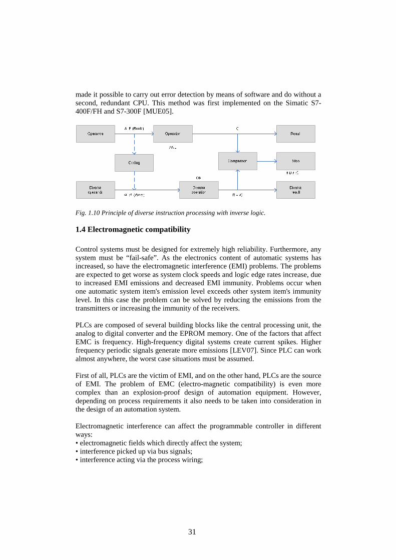
Fig. 1.9 Architecture of the fault-tolerant devices. The architecture of the fault-tolerant devices: two central controllers compare their results and switch off the defective device in the event of a fault. The I/O can have a single-channel or redundant configuration. Fail-safe systems usually comprise two redundant CPUs that keep checking each other for fault-free operation. For the F systems the idea of diverse (multi-track) instruction processing is used. This makes it possible to carry out error detection with just one CPU without sacrificing safety levels (TÜV certification to SIL3) [BERG06]. With the principle of diverse instruction processing, the safety program created by the user is executed twice - once normally, and once with inverse logic. In inverse logic, AND becomes OR, for example, A becomes /A (A inverse) and the binary operand BOOL becomes the variable WORD. If the result of the posit ive logic agrees with the inverted result of the inverse logic, there is no error. In addition, diverse program processing is monitored by two independent hardware timers. This
31
made it possible to carry out error detection by means of software and do without a second, redundant CPU. This method was first implemented on the Simatic S7-400F/FH and S7-300F [MUE05].
Fig. 1.10 Principle of diverse instruction processing with inverse logic.
1.4 Electromagnetic compatibility Control systems must be designed for extremely high reliability. Furthermore, any system must be “fail-safe”. As the electronics content of automatic systems has increased, so have the electromagnetic interference (EMI) problems. The problems are expected to get worse as system clock speeds and logic edge rates increase, due to increased EMI emissions and decreased EMI immunity. Problems occur when one automatic system item's emission level exceeds other system item's immunity level. In this case the problem can be solved by reducing the emissions from the transmitters or increasing the immunity of the receivers. PLCs are composed of several building blocks like the central processing unit, the analog to digital converter and the EPROM memory. One of the factors that affect EMC is frequency. High-frequency digital systems create current spikes. Higher frequency periodic signals generate more emissions [LEV07]. Since PLC can work almost anywhere, the worst case situations must be assumed. First of all, PLCs are the victim of EMI, and on the other hand, PLCs are the source of EMI. The problem of EMC (electro-magnetic compatibility) is even more complex than an explosion-proof design of automation equipment. However, depending on process requirements it also needs to be taken into consideration in the design of an automation system. Electromagnetic interference can affect the programmable controller in different ways: • electromagnetic fields which directly affect the system; • interference picked up via bus signals; • interference acting via the process wiring;

32
• interference reaching the system via the power supply and/or protective ground. Figure 1.11 shows the possible routes for electromagnetic interference.
Fig. 1.11 Possible routes for electromagnetic interference. Interference can reach the programmable controller via different coupling mechanisms, depending on the transmission medium (conducted or non-conducted) and distance between interference source and the equipment [FRI01]. The production environment contains several threats, including power transients, radiofrequency interference, electrostatic discharge, and power line electric, and magnetic fields. Since PLCs can work almost anywhere, the worst case situations must be assumed. PLCs as electronics systems may be exposed to very high radio frequency (RF) electromagnetic field levels. To avoid electromagnetic interference, the controller is mounted in a metal panel/cabinet and earthed the power supply. The power supply signal is earthed to the metal using a wire whose length does not exceed 10 cm. If conditions do not permit this, the power supply does not earth [FRE07]. In the case of a process technological system, differentiation is made between the so-called acceptable range, the permissible error range and the unacceptable error range. Here it is assumed that a process technological system in the course of normal operation (steady-state operation) moves within the so-called acceptable range, i.e. in the event of a drifting of process parameters from the working point, the system operates in the permissible error range. The protection of this operating mode is realized by means of the actual automation system, whereby a corresponding monitoring device (limit value encoded) ensures that if the acceptable range is exceeded (steady-state operating status), the system is automatically returned to the acceptable range or, if governed by the process technology, by manual intervention. If this monitoring device fails, then a so-called
33
safety device is indicated, which is also realized by means of a corresponding limit value encoder and at the very least returns the process parameters into the permissible error range. Irrespective of these measures described, an additional safety device must be provided, which comes into effect in the event of failure of the previously described safety technology. This safety device requires a hardware basis which is completely independent of the previous automation equipment, which encompasses both sensors and actuators and also processors. This ensures that in the event of failure of monitoring or safety equipment, an additional automation structure becomes effective in the process technology system, thereby preventing any drifting of the process parameters into the unacceptable error range (system damage or breakdown). Depending on the process class the different specifications of VDIA/DE 2180 must be incorporated in the project design work. The electromagnetic compatibility of the system components with respect to pulse-type interference, electrostatic discharge, burst impulse (rapid transient interference), high energy single pulse (surge), sinusoidal interference, RF radiation (electromagnetic fields) and RF interference on cables and cable shields define in accordance with IEC 61000. The prerequisite for this is that the system meets and complies with the relevant requirements and guidelines relating to electrical equipment. Emitted interference from electromagnetic fields is defined in accordance with EN 5501. 1.5 PLC networks Programmable logic controllers can also be specified with a number of computer interface options, network specifications and features. Various methods of communication are available to cover different requirements. MPI is the low-cost network for small amounts of data. PROFIBUS transmits small to medium amounts of data at high speeds. Industrial Ethernet handles large amounts of data at high speeds. Finally, point-to-point offers a serial link with special protocols. A communication utility specifies how the communication stations are to exchange data and how these data are to be treated. The utility is based on a protocol which describes the coordination procedure between communication partners. A connection defines the relationship between two communication stations. It represents the logical allocation of two stations for execution of a certain

34
communication utility. It also contains special characteristics such as the type of connection (dynamic or static) and how the connection is established.
PLC used in large I/O systems may have peer-to-peer (P2P) communication between processors. This allows separate parts of a complex process to have individual control while allowing the subsystems to co-ordinate over the communication link. These communication links are also often used for HMI devices such as keypads or PC-type workstations. Some PLCs have two serious interfaces and can operate in PPI и Freeport modes [HAS06]. HMI (human-machine interface) combines the world of automation with that of individual operator demands even then, the components provided for this encompassed a wide range including Push Button Panels, Touch Panels and Operator Panels, Windows CE platforms, and PC-based visualization systems, Multi-user process visualization or SCADA systems (Supervisory Control and Data Acquisition). PLCs may need to interact with people for the purpose of configuration, alarm reporting or everyday control. HMI is employed for this purpose. A simple system may use buttons and lights to interact with the user. Text displays as well as graphical touch screens are available. Most modern PLCs can communicate over a network to some other system, such as a computer running a SCADA system or web browser. The communication functions are the user program's interface to the communication utility. The communication functions are integrated in the CPU's operating system and are called by system blocks for internal PLC communication. Loadable blocks are available for communication with external devices through communication processors. Widespread methods for communications with PLC are: RS-232/RS-485 89%, Ethernet – 86%, 4-20 mА/0-10V DC – 81% [ZAN06]. Any controller within the network can be both master and slave. In order to be read by the master, a slave's application must contain the PLC to PLC (IEC62014-3). Using UDP to implement controller-to-controller communication PC to PLC, accessing PLC via SCADA enables the SCADA application to access the PLC. The PLC is defined as a slave device. Some equipment may come with only serial protocol interfaces (e.g. RS232, RS485) [WEI03]. The system is based on balanced circuits with twisted-pair wires (A and B). The data conversion of logical 0 and 1 is made by converting the polarity of the two wires by reference to each other, instead of changing polarity of a single wire by reference to the "SG" (Signal Ground).

35
The noise immunity results from the fact that, when electromagnetic noise is induced over the differential signals, the same noise is induced on both signals. When the receiver subtracts the differential signals, the result is noise compensation. The same two wires are used for transmitting and receiving; therefore, within RS485 networks, only one device can transmit while all of the other devices 'listen' (receive). Baud rates of 19.2 kbps to 12 Mbps are possible for interfaces of the type MPI/DP. Transmission rates of 9.6 kbps to 12 Mbps are possible for PROFIBUS-DP interfaces. According to research the controller with Ethernet communication protocol and an integrated HTTP Web server is widely used [ZAN06]. Automation systems networks are defined by the international standards: Indusrial Internet (IEEE 802), PROFINET (IEC 61158), PROFIBUS (IEC 61158/EN 50170), AS-Interface (EN 50295), EIB (EN 50090, and ANSI EIA 776). The special modules are a physical connection between the Internet, Ethernet and PLC bus. They permit the PLC system to be connected to Industrial Ethernet (IE). The PLC can be configured, programmed, and diagnosed via Ethernet even at a geographical distance. In addition, diagnostic messages can be e-mailed from a system. Sending an e-mail was initiated by the PLC user program [MUE05]. The fieldbus systems have been successfully introduced in the industrial automation. The usage of Ethernet-based local communication systems in this domain ensuring the real-time behaviour of these systems is being developed. Profinet IO provides the service definition and protocol specification for real-time communication based on Ethernet, IP, and UDP for the field area. It defines services and protocols mainly for communication between IO controllers (PLC) and IO devices (Remote IO). It includes the architecture for real time control and alarm messages taking precedence over parameter, diagnosis, or infrastructure messages including other TCP or UDP based protocols. High message priorities in combination with the time division multiplexing approach with the direct data link layer access provide short cycle times and low jitter. PROFIBUS transmits small to medium amounts of data at high speeds. The transmission medium is a shielded two-wire cable. The transmission speed determines the length of the cable within a segment. The maximum length at the highest transmission speed (12 Mbit/s) is 100 m, and 1000 m at the lowest transmission speed (9.6 kbit/s). The maximum number of stations is 127. Stations can be active or passive. An active station receives a certain amount of time to access the bus and send data telegrams. After the allocated time expires, the station passes the token (access
36
rights) to the next active station. This procedure is called token passing. When passive stations (slaves) are assigned to an active station (master), the master communicates with its slaves while it has the token. A passive station cannot receive the token. All PROFIBUS use token passing and are based on the ISO-OSI model. PROFIBUS DP for decentralized periphery links intelligent masters to slave devices. PROFIBUS-PA, designed for process automation in hazardous areas, permits the construction of an intrinsically safe network. PROFIBUS-PA is linked by the segment coupler devices [BER02].
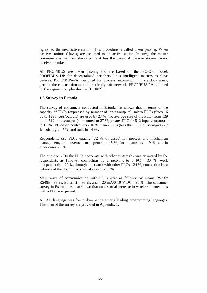
1.6 Survey in Estonia The survey of consumers conducted in Estonia has shown that in terms of the capacity of PLCs (expressed by number of inputs/outputs), micro PLCs (from 16 up to 128 inputs/outputs) are used by 27 %, the average size of the PLC (from 129 up to 512 inputs/outputs) amounted to 27 %, greater PLC (> 512 inputs/outputs) – to 18 %, PC-based controllers - 10 %, nano-PLCs (less than 15 inputs/outputs) - 7 %, soft-logic - 7 %, and built in - 4 % . Respondents use PLCs equally (72 % of cases) for process and mechanism management, for movement management - 45 %, for diagnostics - 19 %, and in other cases - 6 %. The question - Do the PLCs cooperate with other systems? - was answered by the respondents as follows: connection by a network to a PC - 30 %, work independently - 29 %, through a network with other PLCs - 24 %, connection by a network of the distributed control system - 18 %. Main ways of communication with PLCs were as follows: by means RS232/ RS485 - 89 %, Ethernet – 86 %, and 4-20 mA/0-10 V DC - 81 %. The consumer survey in Estonia has also shown that an essential increase in wireless connections with a PLC is expected. A LAD language was found dominating among leading programming languages. The form of the survey are provided in Appendix 1.

37
8
10
14
15
16
19
23
30
30
40
41
0 5 10 15 20 25 30 35 40 45
Respondents, %
PLC with I/O remote subsystems
Universal software for other platforms
PLC with integrated I/O modules
PLC with PC I/O modules
PLC with Web-access
Reserved CPU and I/O remote modules
Micro PLC
PLC with PC
PC-soft controllers
Nano PLC
Others
Fig. 1.12 Results of the survey of consumers in Estonia. 1.7 Conclusions of Chapter 1
1. PLCs are made by means of CMOS technology providing their functioning with the maximal clock frequency at the minimal power consumption. PLCs, similarly to many technologies in automation, support the tendency of the reduction of the sizes, increases in functionality and a set of interfaces, the best compatibility with other kinds of industrial modules. Integration of inputs/outputs modules and the universal software are key opportunities of a PLC.
2. PLCs are considered today as a principal item of automation. Their proven
reliability in harsh environments and design to handle many inputs and outputs has made them the foundation of many factory automated systems.
3. PLCs come in a variety of sizes: large, medium, small, micro, and nano.
They are programmable via software interfaced via standard computer interfaces and proprietary languages and network options.
4. IEC 61131-3 defines five programming languages for the PLC. The
standardization of high level programming languages for a Programmable Logic Controller allows implementing more advanced control strategies in PLC-based control applications.
5. PLC inputs and outputs connect the PLC with the environmental world.
PLC transistor outputs are fast, they switch a small current, have a long
38
lifetime and work with DC only. PLC relay outputs, being slow, can switch a large current, have a shorter lifetime and work with AC or DC. PLC power options; it is important to apply their mounting options and environmental operating conditions in control systems.
6. A fail-safe system stops when an emergency appears. The fault-tolerant
system, by contrast, does not go into stop mode during operation and must therefore be designed so that, in the event of a fault, only the faulty section is switched off.
7. Basic aspects of a process with PLC protection include complex problems,
such as the system diagnostics, EMC, redundancy.
8. PLCs are robust and are typically introduced between the supervision layer and the hardware. Using industrial fieldbus technologies, considerable benefits can be achieved for distributed input/output devices.
39
2 STRUCTURAL SYNTHESIS OF PLC CONTROL WITH THE DISTRIBUTED I/O When inputs and outputs are located at considerable distances from the programmable logic controller, there may be long runs of cabling which are not immediately comprehensible, and electromagnetic interference may impair reliability. Distributed I/O systems are the solution in such cases as the controller CPU is located centrally, and the I/O systems (inputs and outputs) operate locally on a distributed basis. The development of distributed I/O system technology has many advantages since decentralized control results have higher flexibility in the planning process. They allow for better implementation of individual requirements. A plant with distributed control can be extended more easily. Considerable savings can be made particularly in the mechanical installation, fitting and wiring of the plant equipment due to reduced cabling for distributed input/output devices. A second factor is the wide variety of field devices that are available for this technology. To make the most of these advantages, the fieldbus must be of standardized and open architecture. All master systems consisting of a DP master and DP slaves that are connected using a bus cable and that communicate via the PROFIBUS-DP protocol are designated as distributed I/Os. The high-performance PROFIBUS-DP bus system with its high data transmission rates is available for the PLC’s CPU and the I/O system smooth communication.
2.1 Configuring distributed I/Os with PROFIBUS DP Configuring distributed I/Os with PROFIBUS DP is basically to assign DP stations (PROFIBUS nodes) to a DP master system [BER02]. DP master and its connected DP slaves make up a DP master system. The DP master links the controller CPU with the distributed I/O systems. The DP master exchanges data by means of PROFIBUS-DP with the distributed I/O systems and monitors the PROFIBUS-DP bus system. The distributed I/O systems (DP slaves) prepare the data of the sensors and actuators locally so that they can be transmitted by PROFIBUS-DP to the PLC’s CPU. PROFIBUS – a system of field buses which can be used by all equipment of automation, type PLC, РС, НМI-systems, drives and sensors for data exchange. PROFIBUS - DР - the protocol optimized on speed - has been developed

40
specifically for the link between the PLC (DР the wizard) and the devices of the distributed input-output (DP Slaves). The system integration resources are the constituent of the base software modern PLC. Programming of links between controllers and other programmed systems is defined in the standard IEС 61131-5. The network organization represents a universal set of the modular blocks developed for the effective decision of problems of communications for the whole technological process. Such a configuration uses intellectual devices at local level which co-operate with each other on a network. The openness and flexibility allow connection between various systems and expansions. A network segment can comprise a maximum of 32 stations, the entire network can interconnect a maximum of 127 stations. The maximum number of DP slaves in a DP master system is determined by the type of the DP master used. DP masters can be Class 1 masters for the data exchange in the online process mode, and Class 2 masters for service and diagnostic tasks as carried out by a programming device [BER02]. The field equipment for the automation of technical processes (types of sensors, drives, converters and engines) even more often uses the system of field buses for information interchange with blocks of handle of higher level.
2.2 Development of the control system with S7 300, ET200M, Ex I/O modules
The SIMATIC S7 Ex modules S7-300, ET 200M are used for creating the control systems in hazardous areas. The SIMATIC S7 Ex modules have the following license Ex II 3 (2) G EEx nA ib IIC T4. This means that they can be installed in a non-hazardous area and also in zone 2. Only intrinsically safe electrical equipment (actuators/sensors) permitted in zones 1 and 2 can be connected to the SIMATIC S7 Ex modules. Physical isolation of non-Ex signals from Ex signals corresponds to the requirements with regard to the configuration of explosion-protected automation technology. All automation systems are routed to a common ground.
2.2.1 DP master control of the distributed I/O The DP master is the active station in the PROFIBUS network and communicates with its DP slaves by means of cyclic data transmission. SIMATIC S7-300 CPU 315-2 PN/DP with integrated MPI/DP interface, a medium program memory and quantity framework, high processing performance in binary and floating-point arithmetic, is suggested as a DP master in the control system with distributed I/O [WEI03]. SIMATIC Manager controls all transpiring automation data and all tools necessary for processing this data.
41
Data communication with the DP slaves is handled by the process image input and output tables of the CPU, or by direct I/O access commands from the user program. Interfaces and functions are available to handle and evaluate process and diagnostic interrupts. The CPU of the SIMATIC S7 also allows the changing of the parameter sets for the DP and DPV1 slaves from within the program. The configuration data for hardware, the parameter of assigned data for the modules and the connection data for communication are defined and organized in STEP7 software package. The programming and configuration software STEP7 is available to programming an automation task:
• configuring hardware and setting its parameters; • configuring networks, connections and interfaces; • creating and debugging control program.
In a DP master system, a DP master controls only the DP slaves assigned to it. If stations are configured appropriately, another node on the PROFIBUS subnet - master or slave, and referred to as the receiver - can now "listen in" to the input data sent by a DP slave - called the sender - to its DP master.
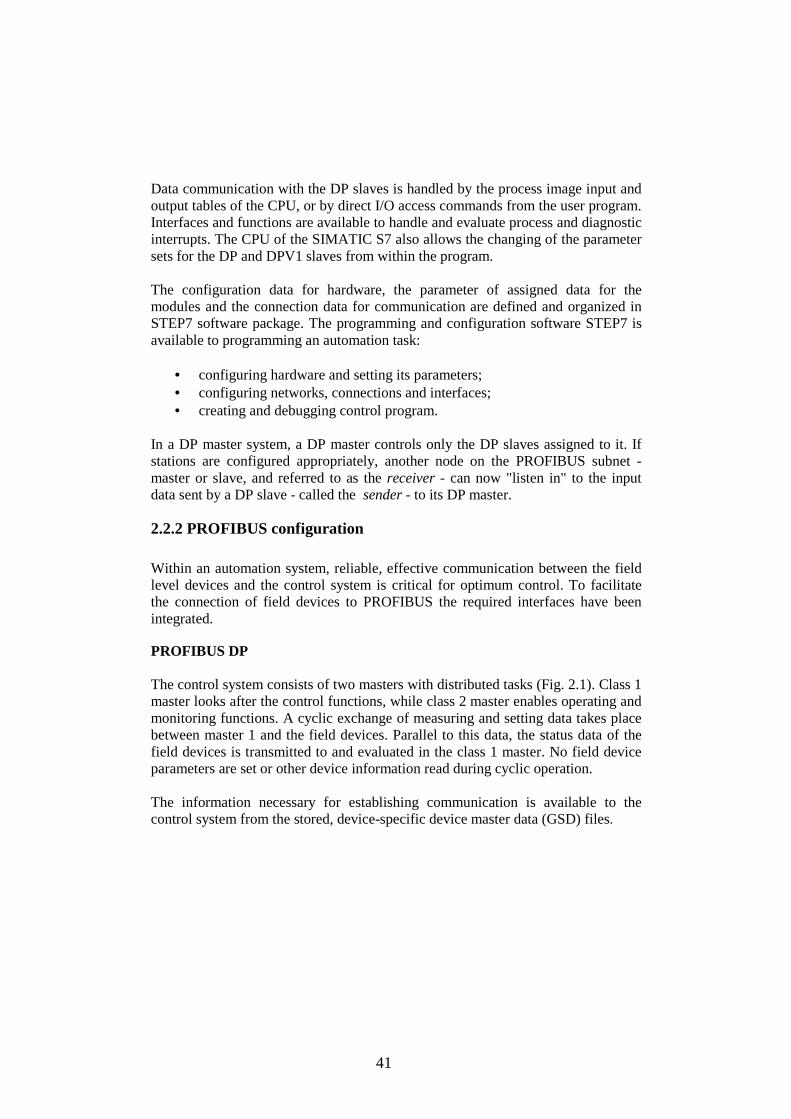
2.2.2 PROFIBUS configuration Within an automation system, reliable, effective communication between the field level devices and the control system is critical for optimum control. To facilitate the connection of field devices to PROFIBUS the required interfaces have been integrated. PROFIBUS DP The control system consists of two masters with distributed tasks (Fig. 2.1). Class 1 master looks after the control functions, while class 2 master enables operating and monitoring functions. A cyclic exchange of measuring and setting data takes place between master 1 and the field devices. Parallel to this data, the status data of the field devices is transmitted to and evaluated in the class 1 master. No field device parameters are set or other device information read during cyclic operation. The information necessary for establishing communication is available to the control system from the stored, device-specific device master data (GSD) files.
42
Fig. 2.1 Configuration of the control system network PROFIBUS. One or more class 2 masters can access the field devices acyclically in addition to the cyclic mode. With this communication type further information can be fetched from the devices or settings made in the devices [WEI03]. Each bus node must receive a PROFIBUS address so that it can be uniquely identified on PROFIBUS-DP. The PROFIBUS address is set in STEP 7 separately for each on of the two PROFIBUS DP networks. Rules for the assignment of a PROFIBUS address: • The valid PROFIBUS addresses are: 1 to 125. • Each PROFIBUS address can only be assigned once in a DP master system.
2.2.3 Addresses in the DP master system A DP master system with the DP master and all DP slaves is integrated in the address structure of the central CPU, since the central CPU addresses the DP slaves as if they were centralized modules. A DP master system contains the following addresses. • Station address Each station in the PROFIBUS subnet has a unique address. This station address is the station number which distinguishes it from all other stations in the subnet. • Geographic address It contains the DP master system ID specified during configuration and the station address on PROFIBUS which corresponds to the rack number. • Logical address, module start address The smallest logical address is the module start address of a CPU. • Diagnostic address DP master has diagnostic data and is addressed with a diagnostic address.

43
2.2.4 Distributed modular I/O systems The distributed modular I/O systems ET 200M are used to connect sensors and actuators to a central controller over PROFIBUS. Distributed I/O devices are available with IP 20 and IP 65/67 degrees of protection, also with integral safety technology, and as intrinsically-safe devices for use in hazardous areas. The structure of the input and output area of the modular DP slaves ET200M is variable. This structure is defined when the DP slave is configured using S7 software HW Config. Station SIMATIC ET 200M includes alarm and functional modules, the power unit module in the structure. Connection to network PROFIBUS-DP is made through the interface modules IM 153-2. The internal bus signals are passed on from module to module via a bus connector. The active bus sub-modules are used on to which the modules are snapped, the modules can be replaced during running operation (hot swapping). The ET 200M is used together with S7-300 modules possessing the characteristics in the environments with increased demands. ET 200M is also suitable for redundant operation in fault-tolerant systems. The fail-safe S7-300 modules can be used in the ET 200M - also mixed with standard modules. In association with Ex digital modules, intrinsically-safe sensors and actuators can be connected from zones 1 and 2 of plants subject to explosion hazards. In network PROFIBUS-DP station SIMATIC ET 200M carries out functions of the passive (conducted) device. IM 153-2 is used also as DP V1-Slave in a combination to the DPV1-master for use of additional acyclic functions DPV1- Slave. The PROFIBUS subnet is used to establish a link to the decentralized periphery. The PROFIBUS DP communication utility is implicitly included.
2.2.5 Transfer memory with intelligent DP slaves The master CPU does not have direct access to the input/output modules of intelligent DP slaves. For this reason, each intelligent DP slave has a transfer memory which can be divided into several sub-areas of different lengths and data consistencies. Depending on its division, each intelligent DP slave appears to the master CPU as a compact or modular DP slave. The addresses of the transfer memory are entered during configuration. The addresses are specified from the standpoint of the slave CPU during the configuration of the intelligent DP slave. The addresses are specified from the standpoint of the master CPU when the intelligent DP slave is added to the DP

44
master system. From the standpoint of the DP master, the addresses of the transfer memory may not conflict with the addresses of other modules in the (central) S7 station. From the standpoint of the slave CPU, the addresses of the transfer memory may not overlap with those of the modules of the intelligent DP slave [WEI03]. Regarding user data access and data consistency, the address areas of the transfer memory are handled as individual modules (the lowest address of an address area is the module start address).
2.3 PROFIBUS PA PROFIBUS PA (Process Automation) has a special transmission method and therefore satisfies the requirements of process automation and manufacturing engineering. This transmission method is defined in the international standard IEC 61158-2. The low transmission speed reduces the power loss compared to the PROFIBUS-DP and therefore enables an intrinsically safe technique for use in hazardous areas. PROFIBUS PA uses the expanded PROFIBUS DP protocol for data transmission. In addition, it implements the PA profile which specifies the characteristics of the field devices. The PROFIBUS PA enables bi-directional communication between a bus master and the field devices via a shielded two-wire line. At the same time the power is supplied to the two-wire field devices on the same lines. PROFIBUS PA is designed specially for the high-speed and reliable communication required in automated process engineering. With PROFIBUS PA sensors and actuators are linked to a common fieldbus line, even in potentially explosive areas.
2.3.1 Interfacing Two network components are available for linking PROFIBUS DP and PROFIBUS PA, namely the DP/PA coupler if the PROFIBUS DP can be operated at a transmission rate of 45.45kbit/s, and the DP/PA link which converts the transmission rates of PROFIBUS DP to the transmission rate of PROFIBUS PA. Parameterization is carried out using STEP 7. PROFIBUS PA devices are integrated in PROFIBUS DP networks by segment couplers. Depending on the size of the system and thus the number of field devices and the required timing, the system must be implemented with one or more PROFIBUS-PA channels. A PROFIBUS PA channel consists of the components shown in Fig. 2.1.

45
The signal conversion DP/PA, bus feeding and bus termination functions are combined in a coupling module. Depending on the number of PROFIBUS-PA field devices to be operated in the automation system and the required timing, a DP/PA coupler or, in the case of higher requirements, a more powerful DP/PA link is used (Fig. 2.1). In the system configuration, several PROFIBUS PA channels are connected to the fast PROFIBUS-DP with coupling units. The PLC is also linked to this. Both bus systems use a uniform protocol layer. This makes the PROFIBUS PA a communication-compatible extension of the PROFIBUS DP into the field. Concerning top level systems (automation devices) connector DP/PA link is DP slave, and concerning systems of the bottom level – the DP-master. Connector DP/PA link realises network transition from the master system PROFIBUS DP to PROFIBUS PA. In this case both bus systems physically work independently through IM 153-2 (galvanic communication) with the reports and time format.
2.3.2 DP/PA coupler The module of the communication DP/PA coupler is a physical connection between PROFIBUS DP and PROFIBUS PA. At independent work it gives a chance to address field devices PA through PROFIBUS DP. The module of communication DP/PA coupler realises transfer between PROFIBUS DP and PROFIBUS PA to which field devices PA are connected. In the drawing (Fig. 2.2) integration of the communication module DP/PA coupler in the system is shown. The module of communication DP/PA coupler Ex i is used to connect field devices PA in harsh environments.
Fig. 2.2 Integration of DP/PA coupler in a system.

46
2.3.3 Defining cable lengths The maximum line length in a MPI subnetwork is 50 m for a baud rate of up to 187.5 Kbaud with non-isolated interfaces. Between nodes with isolated MPI interface the line length of a segment can be up to a maximum of 1000 m, provided the transmission rate of 187.5 Kbaud is not exceeded.
PROFIBUS PA cable cannot be used for PROFIBUS DP cable in a hazardous area, because the two protocols differ in their conversion of the physical layer (OSI model). Whereas PROFIBUS PA is based on the IEC 61158-2 standard, PROFIBUS DP uses the RS485 standard in the electrical version. Therefore the physical properties of the cable are different. PROFIBUS PA and DP cables differ in surge impedance, loop impedance, and signal attenuation.
An additional terminating resistor T is fitted at the far end of the bus for transmission-technical reasons. When using the recommended bus cable, the theoretically possible line length (sum of all line sections) is a maximum of 1900 mm. The voltage drop over the lines supplying the field devices must be taken into account in the planning. The individual field devices can be connected almost anywhere in the bus system. DP/PA-coupler or DP/PA-Link is supplied by a power supply unit with SELV Safety ExtraLow Voltage). This power supply has adequate reserves for bridging brief power failures. The DP/DP Coupler can only be operated as a DPV1 slave in combination with a DPV1 master. The additional functions (acyclical services) of a DPV1 slave can only be used if this is the case. DP slaves defined as DPV1 slaves in their GSD file can be selected from a dropdown list for operation in DPV1 or DPV0 mode. This GSD file is included in STEP 7. DPV1 is supported with full and uniform diagnostic functions [WEI03].
2.4 PA intelligent device analysis In harsh process conditions with high chemical and physical abuse, reliability and accuracy are critical for safe and economical operation. Throughout the shale-chemical industry, measurement requirements can be extreme. Everyday tasks include different measurements and call for an individual solution. Because the measurements are carried out in extremely harsh ambient conditions, specialized process instruments (e.g. pressurized enclosures) are often required for the safety-relevant approvals (ATEX, FM, SIL, WHG).
47
Modern PA devices are intelligent and execute part of the information processing in automation systems. This was previously done by the PLCs or DCS systems. The PA profile is designed in co-operation with the process industry and defines all functions and parameters for different classes of instruments. It is based on internationally accepted function block technology. A PA device has three function blocks.
• A Physical Block describes the necessary parameters and functions of the device itself (software version, serial number, vendor ID, reset command).
• A Transducer Block contains parameters which have effect on or describe the type of sensor or actuator. Transducer blocks may also contain parameters for calibration and linearization. The processed information is passed on to the Function Block. If a device has more sensors, it has corresponding Transducer Blocks for every sensor.
• Function Block contains one or more cyclically accessible inputs or outputs parameters (process values). These can be of analog or discrete nature. Other parameters: setup scaling, alarms and unit factorization.
Some devices consume more power when there is a problem with itself. The FDE (Fault Disconnection Electronics) current is this additional static/basic current consumption. Some devices have no FDE current. When there is a problem they consume the same current. But when the problem becomes worse, the device shuts itself down from the bus (no more power consumption). The control system consideration is to provide the possibility to connect programming devices as well as operator panels, slaves or DP standard slaves of other manufacturers to a PROFIBUS DP network. EMERGENCY-OFF equipment to IEC 6204 retains an operational state in all operating modes of a system [EXP06].
2.5 Configuring the network The network configuration tool, NetPro, provides the graphical presentation and documentation of the networks and their stations and sets up the subnets and stations (Fig. 2.3).

48
Fig. 2.3 NetPro: configuring network window. NetPro also shows a graphic presentation of a DP master system with all its DP slaves, which can then be edited. The communication connections are configured in the connection table.
2.6 Designing a PLC system There are many methods for PLC system design, approaches to company procedures and practices accepted for training and location [ISO 11064].
The controlled object is divided into sections that have a level of independence of each other. This determines the boundaries between the controllers and the influence of the functional description specifications and the assignment of resources. The descriptions of operation for each section of the the controlled object are written, including the I/O points, functional description of the operation, states that must be achieved before allowing action for each actuator or sensor, description of the operator interface, and any interfaces with other sections of the process or machine. Besides this, equipment requiring hard-wired logic for safety is identified. Control devices can fail in an unsafe manner, producing unexpected startup or change in the operation of machinery. Where unexpected or incorrect operation of the machinery could result in physical injury to people or significant property damage, consideration should be given to the use of electro-mechanical overrides which operate independently of the PLC to prevent unsafe operations. In the design of safety circuits the following tasks are considered:
• Identifying unexpected operation of actuators that could be hazardous. • Identifying the conditions that would assure the operation is not hazardous,
and determine how to detect these conditions independently of the PLC.

49
• Definition how the PLC CPU and I/O affect the process when power is applied and removed, and when errors are detected.This information should only be used for designing for the normal and expected abnormal operation, and should not be relied on for safety purposes.
• Designing manual or electro-mechanical safety overrides that block the hazardous operation independent of the PLC.
• Providing appropriate status information from the independent circuits to the PLC so that the program and any operator interfaces have necessary information.
There is generally sufficient company documentation available for problems such as explosion protection (explosion-proof design of automation equipment and systems), whereby the requirements arising from process technology can be implemented quite successfully [EN 50019], [EN 50020]. Similarly, the problem of lightning protection must comply with its proper place in this context, since it also plays an important role in advanced system automation [IEC 62305].
2.7 Installation of PLC The installation of a PLC is designed to be safe and easy and it is selected in accordance to the local and national standards. Units should not be installed in areas subject to the following conditions: excessive or conductive dust, corrosive or flammable gas, moisture or rain, excessive heat, regular impact shocks or excessive vibration [BOL03]. Always the mounted units and blocks are kept as far as possible from high-voltage cables, high-voltage equipment and power equipment. The input signals should not be installed in the same multicore cable as output signals or the same wire. I/O signal cables should not be installed next to power cables or allow them to share the same trunking duct. Low voltage cables should be reliably separated or insulated with regard to high voltage cabling. Where I/O signal lines are used over an extended distance, consideration for voltage drop and noise interference should be made. All power cables must be at least 2 mm2 (AWG 14) [BOL03]. During emergencies all circuits to and from the unit or unit configuration should be turned off using a switch external to that configuration. The active system should have a reliable method of fully isolating the high voltage. Ground resistance must be less than 100 Ω (class 3). The ground cable must not be connected to the same ground as the power circuits.

50
If the system being installed uses the service supply from both the PLC and a powered extension block, then the 0V terminals should be linked. An external power supply is not connected to the PLC 24V terminal. Common errors appear when the I/O devices have been used outside its specified operating range or an input signal occurs in a shorter time period than that taken by one program scan or 24V DC power supply is overloaded.
2.8 Equipotential bonding of explosion protected systems
Potential differences may develop between the bodies of electrical equipment which are bonded to a protective conductor and the conductive elements of the construction which do not belong to the electrical equipment, for example, the piping. The bridging of such potential differences may cause the ignition sparks. Equipotential bonding requires that conductive metal parts which are not touch-protected are interconnected with the ground conductor. A practical central point for equipotential bonding is the distribution cabinet. The cross-section of the equipotential conductor should at least be equivalent to that of the corresponding protective conductor. In general, the minimum cross-section of the equipotential conductor is 10 mm2 Cu [DEN06].
The backplane bus and I/O power circuits of Ex modules feature galvanically isolated, i.e. equipotential bonding is not required for these modules. Where lightning protection devices are required in the intrinsically safe circuit, they must be connected to the EB conductor at the same point as the shield of the intrinsically safe circuits. Generally, cable racks must be incorporated throughout the earthing system [DEN06].
2.9 Conclusions of Chapter 2
1. DP distributed I/O system allows installation of the I/O modules connecting the PLC to the control object in its vicinity, at a distance from the PLC.
2. The distributed I/Os are linked to the central controller with minimum
wiring by means of the PROFIBUS bus systems. 3. The benefit of PROFIBUS compared to other systems is that the only
PROFIBUS can be used in all parts of the plant (upstream, process and downstream).
51
4. PROFIBUS known as “open” is a bus with international standards and for which various manufacturers can provide the controllers and the compatible interfaces.
5. According to ATEX the hazardous areas are classified into zones (0, 1 or 2
for gasses and vapours, 20, 21 or 22 for dust). 6. A fieldbus topology for a safe area application includes a control system
with a fieldbus communication controller, the fieldbus cable, and some instruments.
7. Most of the instruments are bus-powered and the communication signal is
on top of the power supply on the same pair of wires (shielded twisted pair fieldbus cable).
8. The main advantage is the real saving that can be made through reduced
cabling outlay and reduced costs for planning, assembly, comissioning and maintenance.

52
3 DEVELOPMENT OF THE DESIGN METHOD FOR AN EXPLOSION PROTECTED CONTROL SYSTEM
3.1 Control system hardware structure The liquids are pumped into appropriate tanks for temporary storage. To prevent these tanks from overflowing and thus reducing the risk of costly cleanup and removal operations, a built-in overflow protection device continuously monitors the level in the tank – a good solution that is also a legal requirement [BES07]. The technological parameters, such as temperature, pressure, and liquids density should also be measured. The pump controls are to be equipped with intelligent actuators [ING06]. Geographically, the park of DGO tanks occupies a certain territory (Fig.3.1). At a great distance, installation of the control system inputs and output is difficult and confused. Electromagnetic compatibility influences the reliability. For work with this system the distributed inputs/outputs configuration is used. At high speed of transfer PROFIBUS DP provides a stable relation between CPU control systems and devices of the distributed input/output. The bus topology is freely selected so that line structure is possible. Some kinds of field devices, such as sensors, are connected to the PROFIBUS PA, while the actuators are connected to the PROFIBUS DP.
Fig. 3.1 DGO storage tank park. Sensors (Fig. 3.2) are connected on PROFIBUS PA and under requirements ATEX: on one DP/PA coupler there may not be more than ten sensors. In that case a current does not exceed 110 mА [WEI03].

53
In the configuration there are six DP/PA couplers: five from them for ten sensors, the 6th is a reserve item. For a lining in Еx zones a cable of type A is used with a special geometrical profile according to IEC 61158–2. The sensors are fed from the same cable (to 110мА), the same cable for a feed and an information signal is used. For the actuators control circuit 15 actuators (at tanks) are connected on the first segment of PROFIBUS DP, 16 (at tanks) are on the second, and 18 are connected (at pumps) on the third. Such a configuration is caused not by the requirements of ATEX, but by the geographical location of the control system actuators. As the DP master the controller S7-300 CPU 315-PN-DP is used in the configuration of network PROFIBUS. It operates 53 sensors and 49 actuators.
3. 2 Configuration of the control project according to demands The following requirements in terms of control system engineering are set on the controllers: 1. reliability through duplication of controllers with the possibility of hot replacement and unaccented transition to the working controller; 2. possibility of construction distributed PLC systems. The functions carried out by the devices of automatic control in the developed control system are: 1. equipment diagnostics; 2. measurement and the control of technological parameters and definition of the reasons of the emergency occurrence; 3. the alarm system (light and sound) at a fault of technological parameters and an emergency condition of the equipment; 4. logic control of blocking and protection; emergency switching-off the process equipment; 5. control of the actuators.
3.2.1 Connection of sensor controls and actuators to PLC The configuration and adjustment of the connected measuring sensors and actuators were carried out by means of SIMATIC Manager. With the help the HW Сonfig utility it is possible not only to configure and address to the hardware configuration of the corresponding equipment, but also to see all knots in the form of the hardware catalogue.

54
Fig. 3.2 Arrangement of sensors on tanks. With a network of Ex, the requirement that all schemes should be spark-preventive is obligatory. It is reached either by current decrease, or by a special lining of a cable. Ех coupler gives out 110мА that provides sparks/arches no-appearing, for example, at breakage or switching. Master systems PROFIBUS PA Configuration was carried out by means of STEP7. Necessary field PA-devices moved out from the hardware catalogue of in PA master system so that they were displayed under IM 153-2. PROFIBUS network configuration for sensors in all ten storage tanks is shown in Fig. 3.3.

55
Fig. 3.3 PROFIBUS network configuration for sensors in 10 storage tanks. Table 1 shows the addresses of sensors in tanks. Table 3 Addresses of sensors in tanks Addresses of sensors in tanks Е-1 - Е-10 PIR LIRA LIR QIR TIR E-1 266-270 286-287 276-280 271-275 256-260; 261-265 E-2 281-285 298-299 288-292 293-297 300-304; 305-309 E-3 310-314 315-316 317-321 322-326 327-331; 332-336 E-4 337-341 342-343 344-348 349-353 354-358; 359-363 E-5 364-368 369-370 371-375 376-380 381-385; 386-390 E-6 391-395 396-397 398-402 403-407 408-412; 413-417 E-7 418-422 423-424 425-429 430-434 435-439; 440-444 E-8 445-449 450-451 452-456 457-461 462-466; 467-471 E-9 472-476 477-478 479-483 484-488 489-493; 494-498 E-10 499-503 504-505 506-510 511-515 516-520; 521-525
3.2.2 PROFIBUS DP for INTELLI+ The new motor management system supplies considerably more data and offers the possibility for comprehensive service functionalities [WEI03]. 49 pump drives are retrofitted with the new management system in the first step. The new process control system is in full operation, the devices will be connected via the
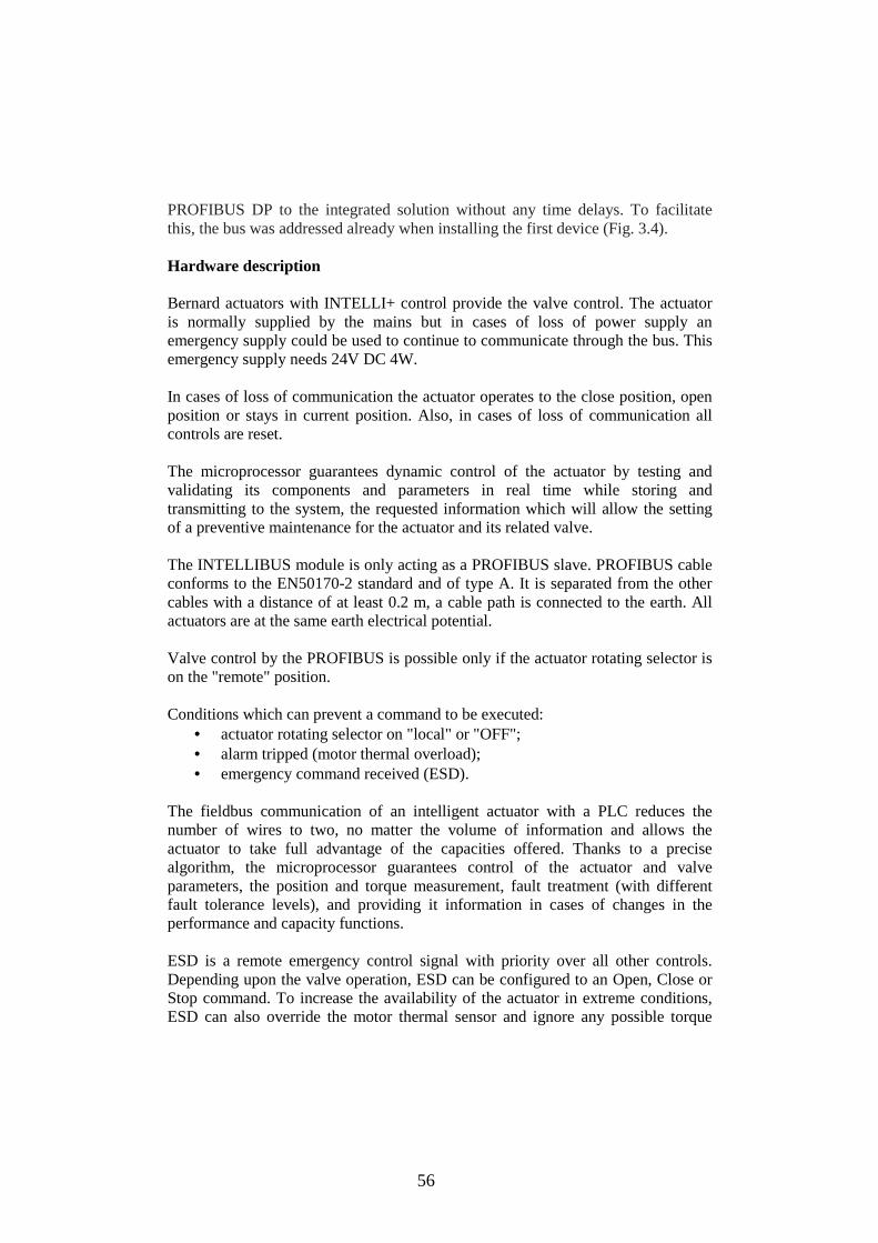
56
PROFIBUS DP to the integrated solution without any time delays. To facilitate this, the bus was addressed already when installing the first device (Fig. 3.4). Hardware description Bernard actuators with INTELLI+ control provide the valve control. The actuator is normally supplied by the mains but in cases of loss of power supply an emergency supply could be used to continue to communicate through the bus. This emergency supply needs 24V DC 4W. In cases of loss of communication the actuator operates to the close position, open position or stays in current position. Also, in cases of loss of communication all controls are reset. The microprocessor guarantees dynamic control of the actuator by testing and validating its components and parameters in real time while storing and transmitting to the system, the requested information which will allow the setting of a preventive maintenance for the actuator and its related valve. The INTELLIBUS module is only acting as a PROFIBUS slave. PROFIBUS cable conforms to the EN50170-2 standard and of type A. It is separated from the other cables with a distance of at least 0.2 m, a cable path is connected to the earth. All actuators are at the same earth electrical potential. Valve control by the PROFIBUS is possible only if the actuator rotating selector is on the "remote" position. Conditions which can prevent a command to be executed:
• actuator rotating selector on "local" or "OFF"; • alarm tripped (motor thermal overload); • emergency command received (ESD).
The fieldbus communication of an intelligent actuator with a PLC reduces the number of wires to two, no matter the volume of information and allows the actuator to take full advantage of the capacities offered. Thanks to a precise algorithm, the microprocessor guarantees control of the actuator and valve parameters, the position and torque measurement, fault treatment (with different fault tolerance levels), and providing it information in cases of changes in the performance and capacity functions. ESD is a remote emergency control signal with priority over all other controls. Depending upon the valve operation, ESD can be configured to an Open, Close or Stop command. To increase the availability of the actuator in extreme conditions, ESD can also override the motor thermal sensor and ignore any possible torque

57
overload that may be previously set. All communications between the actuator and the system (commands and information) are transmitted on the same unique line. Field bus connection The INTELLIBUS, a PROFIBUS-DPV1 slave module, is controlled by two masters PROFIBUS-DP: PLC and PC. The PROFIBUS DPV1 interface is used for the Bernard actuators with INTELLI+ control. This interface is compliant with PROFIBUS DP (V0) and PROFIBUS DPV1. Hardware communication standard: RS 485. The PROFIBUS DPV1 interface has been specially designed for the Bernard actuators with INTELLI+ control. INTELLI+ includes a control logic and power contactors. It ensures the full control of the actuator including status reports, fault treatment and protections. Up to 17 different types of faults and alarms can be reported. A fundamental feature of the developed control system is the autonomous execution of all protection and control functions. This means that even if the bus system or the process control technology fails, the motor feeder maintains its operation and protection. Even a particular behaviour for fault cases can be parameterized [GDA02]. Two PROFIBUS interface boards are built in the actuator with isolated connections to the PROFIBUS lines. In cases of failure along a line, the PLC can still communicate through the other line. Bus is electrically totally isolated from the actuator circuitry. In cases of a redundant version, each input is electrically isolated from the actuator circuitry and they are isolated from each other. A loss of actuator power supply does not lead to a field bus disruption. PROFIBUS DP architecture The PROFIBUS cable coming from the PLC is connected to the first actuator, then the PROFIBUS cable links this actuator with the next one and so on. All actuators are connected to the line one after the other until the last one. No return to the PLC is required. A termination was installed at each end of line. Adding repeater modules allowed increasing both the number of actuator on the line and the total line length. The important advantage of the repeater compared to other repeater-free technologies is to keep the communication speed unaffected and therefore to achieve a very short response time.

58
Fig. 3.4 PROFIBUS network configuration for 49 actuators. Repeaters are also used to achieve additional bus lines at a low cost if placed at PLC output. Each line is independent of the other and therefore a problem on the line does not affect the others (Fig. 3.5). The bus interface is used for sending commands and data over a single line. Specific documentation details the methods for addressing the individual actuator and provides a list of addresses for accessing all commands or data sources. Lost communication is used to configure the fail-safe position. This function is active in the standard configuration, and the actuator remains in the same position if communication is lost. Special PROFIBUS cable conforms to the EN50170-2 standard and of type A [WEI03].

59
Fig. 3.5 Configuration PROFIBUS for Bernard actuators. Maximum line length is reduced according to the communication speed: Table 4 Maximum line length according to the communication speed Transmission baud rate
≤93.75 kbit/s 187.5 kbit/s 500 kbit/s 1.5 Mkbit/s
Maximum line length
1200 m 1000 m 400 m 200 m
Acyclic communications The INTELLIBUS supports acyclic communication (extension V1 of the PROFIBUS protocol) which allows reading the actuator’s state, and reading out all its configurations. Master class 1 supports cyclic communication. It is the same PLC which manages the actuators. Master class 2 supports all the acyclic communication. It can be included to PROFIBUS without interference. A laptop equipped with a PROFIBUS module and PDM software is used as master class 2 anywhere on the line. The INTELLIBUS supports the Read and Write messages of master class 1 (MSAC1_Read, MSAC1_Write). For master class 2, this interface supports Initiate, Abort, Read and Write services. Interface board supports a maximum of 2 simultaneous class 2 master connections. Actuators control bits are located at the addresses 0 to 4 on the INTELLIBUS module.
3.2.3 Configuration software for all process devices For Configuration master system PROFIBUS PA and parametrization field devices PA, additional software S1МАТIС РDМ is used. Field PA-devices are integrated

60
in SIMATIC PDM and in STEP 7 as standard slave through their DDBF-files [WEI03]. SIMATIC PDM (Process Device Manager) is the uniform software tool for central access to all communication-capable process devices within a system. It facilitates the manufacturer-independent operation, adjustment, maintenance and diagnostics of intelligent process devices. All devices and procedures integrated in process automation system are safely under control (Fig. 3.7). SIMATIC PDM contains a simple process monitor of the process values, alarms and status signals of the device.
Fig. 3.7 SIMATIC PDM in the PROFIBUS configuration. SIMATIC PDM complies with NAMUR specification NA64 on status signaling of field devices and supports the NAMUR recommendation NE91 on plant-oriented asset management. The process devices’ diagnostics options in connection with PROFIBUS communication and the Electronic Device Description (EDD) are used in PDM. SIMATIC PDM ensures functioning, service and automatic diagnostics of intellectual devices. SIMATIC PDM supports some communication reports and keeps in contact:
• with the devices equipped with built in interface PROFIBUS-DP and connected directly to network PROFIBUS-DP (actuators);
• with the devices equipped with built-in interface PROFIBUS-PA, connected to segment PROFIBUS-DP through modules or communication blocks DP/PA (measuring devices).
Device adjustment is carried out by means of a configuration mask, enclosed in the tool. The structure of the construction of the interface meets the requirements of standard DIN V19259.
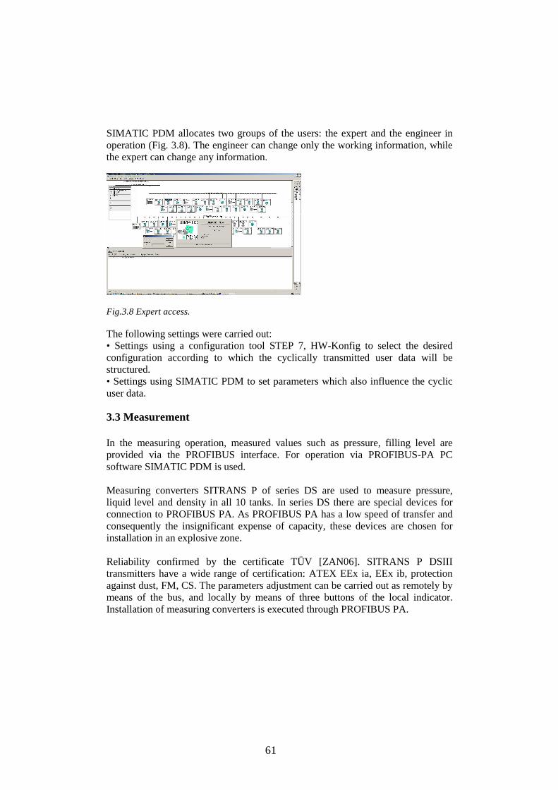
61
SIMATIC PDM allocates two groups of the users: the expert and the engineer in operation (Fig. 3.8). The engineer can change only the working information, while the expert can change any information.
Fig.3.8 Expert access. The following settings were carried out: • Settings using a configuration tool STEP 7, HW-Konfig to select the desired configuration according to which the cyclically transmitted user data will be structured. • Settings using SIMATIC PDM to set parameters which also influence the cyclic user data.
3.3 Measurement In the measuring operation, measured values such as pressure, filling level are provided via the PROFIBUS interface. For operation via PROFIBUS-PA PC software SIMATIC PDM is used. Measuring converters SITRANS P of series DS are used to measure pressure, liquid level and density in all 10 tanks. In series DS there are special devices for connection to PROFIBUS PA. As PROFIBUS PA has a low speed of transfer and consequently the insignificant expense of capacity, these devices are chosen for installation in an explosive zone. Reliability confirmed by the certificate TÜV [ZAN06]. SITRANS P DSIII transmitters have a wide range of certification: ATEX EEx ia, EEx ib, protection against dust, FM, CS. The parameters adjustment can be carried out as remotely by means of the bus, and locally by means of three buttons of the local indicator. Installation of measuring converters is executed through PROFIBUS PA.

62
Adjustment parameters, using the configuration tool HW-Konfig is carried out. According to this configuration cyclically transferred user data will be structured here.
3. 3.1 PROFIBUS test project configuration The PROFIBUS test project for parametrization of five sensors of one storage tank was created (Fig. 3.9). The connection made is based on the technology of the bus line (Fig. 3.10) [WEI03].
Fig. 3.9 PROFIBUS test-bench for five sensors of one tank.
Fig .3.10 PROFIBUS PA field devices. By means of Hardware Configuration utility system DP-master with use DР/РА-linк was established: the interfacing module IM153-2 was inserted into the DP master system. Simultaneously with the DР-slave, the system of the PA-master in the PROFIBUS network (45.45 Kbit/c) was created.
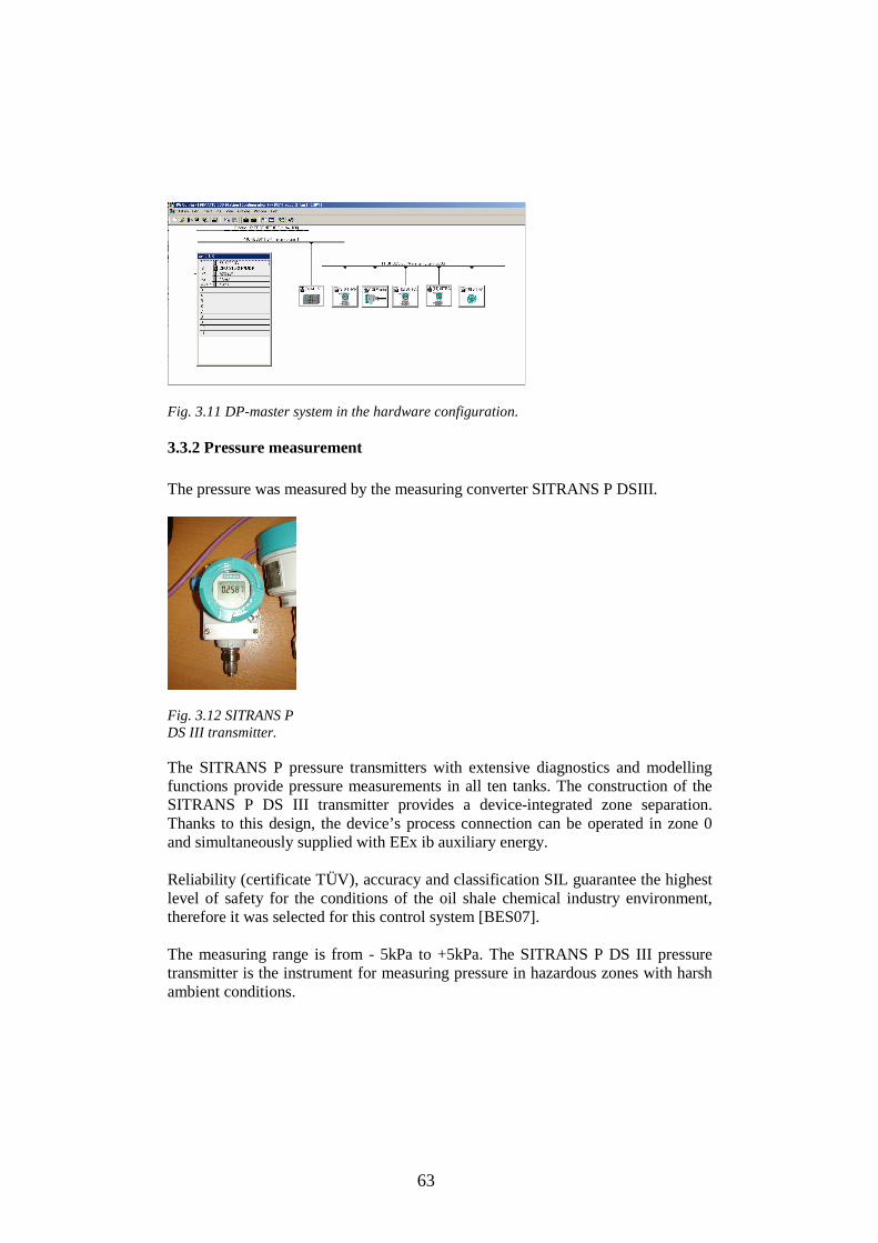
63
Fig. 3.11 DP-master system in the hardware configuration.
3.3.2 Pressure measurement The pressure was measured by the measuring converter SITRANS P DSIII.
Fig. 3.12 SITRANS P DS III transmitter. The SITRANS P pressure transmitters with extensive diagnostics and modelling functions provide pressure measurements in all ten tanks. The construction of the SITRANS P DS III transmitter provides a device-integrated zone separation. Thanks to this design, the device’s process connection can be operated in zone 0 and simultaneously supplied with EEx ib auxiliary energy. Reliability (certificate TÜV), accuracy and classification SIL guarantee the highest level of safety for the conditions of the oil shale chemical industry environment, therefore it was selected for this control system [BES07]. The measuring range is from - 5kPa to +5kPa. The SITRANS P DS III pressure transmitter is the instrument for measuring pressure in hazardous zones with harsh ambient conditions.

64
SITRANS P DS III for pressure measurements has the following parameters: • accuracy ≤ 0.075 % • long-term stability <= 0.25 % / 60 months • measurement range of 1 mbar to 400 bar • certification: ATEX EEx ia, EEx ib, protection against dust, FM, CS • installation through PROFIBUS PA [WEI03]
Fig. 3.13 PDM-mask for SITRANS P.
3.3.3. Level measurement The requirements placed upon level measurement in this project are many. They range from protection against over filling, to measurements in potentially explosive zones – in ten storage tanks. Difficulties at level measurement are: excited environments, tank configurations, installation of the tank, heating system, entrance apertures and exits. Level measurement and detection are crucial in effective stock management and environmental risk reduction. The media to be measured have extreme varying characteristics [CON96]. There are two instruments in each vessel, one for measurement and a redundant unit connected to the back-up safety system. SITRANS P DS III as the level transmitters and the Pointek CLS 300 level switches with these requirements for point level detection and continuous measurement have been redefined.

65
Pointek CLS 300 level switch Using the SIMATIC PDM Communication PROFIBUS PA (IEC 61158 CPF3 CP3/2) remotely, the point level switch Pointek CLS 300 provides high-level detection of the liquids. Pointek CLS 300 is an inverse frequency shift capacitance level switch for detecting liquid surfaces of aggressive chemicals in critical conditions of high temperature and pressure. This capacitance switch handles temperatures up to 400 °C and pressures from full vacuum to 35 bar. For those reasons it was selected for the high level alarm of liquids level in all storage tanks.
Fig. 3.14 Pointek CLS 300 level switch. Pointek CLS300’s microprocessor-based electronics provide one-point calibration, making setup possible without shutting down production process. Pointek CLS300 has a 2-wire loop powered with solid-state switch output, simple push-button calibration and integrated local display, full function diagnostics and PROFIBUS communications for remote commissioning and inspection. Pointek CLS 300 includes patented Active-Shield and Inverse Frequency Shift technology, ensuring high accuracy, resolution and repeatability [ZAN06]. This technology ensures that measurement is unaffected by vapours, product deposits, dust and condensation. The Pointek CLS capacitive limit monitor reliably indicates whether the limit has been reached. On contact with the liquid surface, the dielectric on the sensor changes so that the limit switch reliably signals the attainment of the maximum level. Pointek CLS 300 has KEMA Certificate EC-Type-Examination-Certificate ATEX for use in hazardous locations and NAMUR output.
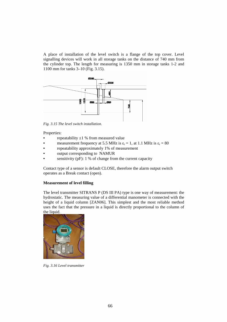
66
A place of installation of the level switch is a flange of the top cover. Level signalling devices will work in all storage tanks on the distance of 740 mm from the cylinder top. The length for measuring is 1350 mm in storage tanks 1-2 and 1100 mm for tanks 3–10 (Fig. 3.15).
Fig. 3.15 The level switch installation. Properties: • repeatability ±1 % from measured value • measurement frequency at 5.5 MHz is εr = 1, at 1.1 MHz is εr = 80 • repeatability approximately 1% of measurement • output corresponding to NAMUR • sensitivity (pF): 1 % of change from the current capacity Contact type of a sensor is default CLOSE, therefore the alarm output switch operates as a Break contact (open). Measurement of level filling The level transmitter SITRANS P (DS III PA) type is one way of measurement: the hydrostatic. The measuring value of a differential manometer is connected with the height of a liquid column [ZAN06]. This simplest and the most reliable method uses the fact that the pressure in a liquid is directly proportional to the column of the liquid.
Fig. 3.16 Level transmitter

67
The input of a level sensor is measured by the differential pressurep∆ , the working range is 0–100 kPa, the output – liquid level Н. The static characteristic is
pkH ∆⋅= ,
where k is the gain:
⋅=kg
sm
gk
221ρ
ρ is the liquid density, g is the acceleration due to gravity and H is the column of liquid [LUY90]. Level calculation For monitoring at the top control level for the operators, the level value should be displayed in meters and in tons. SIMATIC PDM creates communication between measured pressure and the registered level, establishing the following parameters: Нмах (for tanks 3-10) = 5980 (mm) Нmin (for tanks 3-10) = 150 (mm) The level measurement range of 0-100 % corresponds: 150mm – 5980mm. (5980 – 150=5830 (mm)) Нмах (for tanks 1-2) = 7470 (mm) Нmin (for tanks 1-2) = 150 (mm) The level measurement range of 0-100 % corresponds to the following: 150–7470 mm. (7470 – 150=7320 (mm)) The level transmitter SITRANS P DSIII (a scale in PDM (mmH2O)) measurements are connected with the height of a liquid column by the formula:
ОmmНbar 241011 ⋅=
For water with 1g/cm3 density under the formula (the height of a liquid column) will be find:
( )mmHсм
гOmmHp ⋅
=∆ 32 )( ρ (1)
( ) )( 2ОmmНpmmH ∆= (2) The function for the level calculation in mm is defined under the formula (2). The program function for the recalculation in (m) (for a monitoring) is (FC 29).
( ) 1000⋅∆= pmH (3) where H is a value from equation (3),
p∆ is the pressure value.

68
The function for the calculation of liquids levels in tanks 1–10 is called ten times in FC 202. To calculate the level in tons, it is necessary to know the liquid volume. For tanks 3-10: the volume of a dead zone 5.13 m3. The volume of a measured liquid taken into account dead zone is:
( )( ) 32200200 13.5 mmHRV +⋅= π (4)
( )( ) 3200 13.51946.34 mmHV +⋅= (5)
H is a value from Eq. (3). For tanks 1–2
( )( ) 32400400 57.8 mmHRV +⋅= π (6)
A liquid mass in tons:
( )( )[ ] ( )tonsmmHm
kgm 100013.51946.34 3
3 ⋅+⋅
= ρ (7)
( )( )[ ] ( )tonsmmHm
kgm 100057.8117.57 3
3 ⋅+⋅
= ρ (8)
Program functions for mass calculation are FC30 and FC32. These functions are called for 10 times in FC 202 for the calculation of liquids levels in storage tanks 1–10 in tons.
3.3.4 Density measurement and calculation For density measurement, SITRANS P DSIII is established with a working range from 15 kPa to 20 kPa. This method measures the pressure difference of two liquid columns of different height that excludes the influence of controllable liquid level change on the result of the measurement [BES07].
( )2121 HHgppp −⋅=∆=− ρ (9) SITRANS P DSIII – has a PDM scale in mm H2O.
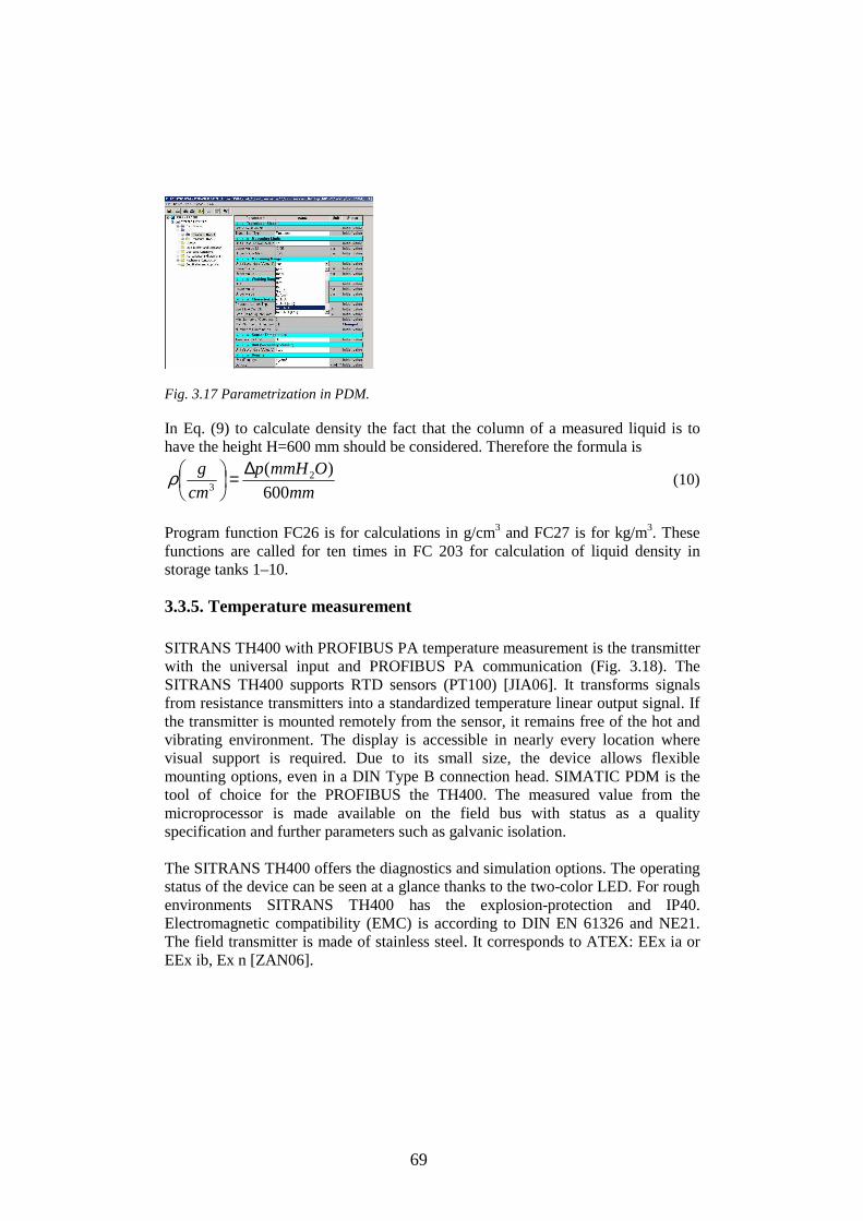
69
Fig. 3.17 Parametrization in PDM. In Eq. (9) to calculate density the fact that the column of a measured liquid is to have the height H=600 mm should be considered. Therefore the formula is
mm
OmmHp
cm
g
600)( 2
3
∆=
ρ (10)
Program function FC26 is for calculations in g/cm3 and FC27 is for kg/m3. These functions are called for ten times in FC 203 for calculation of liquid density in storage tanks 1–10.
3.3.5. Temperature measurement SITRANS TH400 with PROFIBUS PA temperature measurement is the transmitter with the universal input and PROFIBUS PA communication (Fig. 3.18). The SITRANS TH400 supports RTD sensors (PT100) [JIA06]. It transforms signals from resistance transmitters into a standardized temperature linear output signal. If the transmitter is mounted remotely from the sensor, it remains free of the hot and vibrating environment. The display is accessible in nearly every location where visual support is required. Due to its small size, the device allows flexible mounting options, even in a DIN Type B connection head. SIMATIC PDM is the tool of choice for the PROFIBUS the TH400. The measured value from the microprocessor is made available on the field bus with status as a quality specification and further parameters such as galvanic isolation. The SITRANS TH400 offers the diagnostics and simulation options. The operating status of the device can be seen at a glance thanks to the two-color LED. For rough environments SITRANS TH400 has the explosion-protection and IP40. Electromagnetic compatibility (EMC) is according to DIN EN 61326 and NE21. The field transmitter is made of stainless steel. It corresponds to ATEX: EEx ia or EEx ib, Ex n [ZAN06].

70
Fig. 3.18 Intelligent sensor SITRANS TH400. The sensor operating range, limit values, failure behavior, alarm signal for sensor break or short-circuit are programmable. Sensor redundancy is achieved via two sensor inputs. Second sensor for redundancy has an additional address. The accuracy of the PT100 input on a TH400 temperature transmitter is ± 0.03 °C according to Tenth-DIN PT100 temperature probes (Fig.3.19).
Fig. 3.19 SITRANS TH 400 and SpliTConnect.
3.4 Redundancy of the developed system In safety-critical systems some parts of the control system are doubled. An error in one component may then be out-voted by the other. In this redundant system, the system has two sub-components, both of which must fail before the system fails. Since each one rarely fails, and the sub-components are expected to fail independently, the probability of both failing is calculated to be small. The following forms of redundancy are provided in this work: Distributed I/O The redundancy of the slaves was performed using the ET 200M with dual DP ports. Redundant distributed I/O I/Os are connected via two redundant PROFIBUS-DP lines to the ET-200M stations, with redundant IM 153-2 interface modules.
71
The ET 200M distributed I/O station was connected over two IM 153-2 redundant DP slave interfaces over a single channel to both PROFIBUS DP lines. The complete I/O range of ET 200M is available. Dual modular redundant The component which is dual modular redundant has duplicated elements which work in parallel to provide one form of redundancy [GDA 08]. In the developed control system the temperature transmitter has duplicated inputs (addresses in storage tank E1 are 256-260; 261-265), so that should one input fail, another is ready to carry on its work. Redundancy of the actuators helps overcoming the risk of cut wires by doubling the cable. If the first one fails, the communication automatically switches to the second board. The redundancy function is also secured by the implementation of two Profibus boards in the INTELLI+ box. Diagnostics and repair
All standard diagnostic functions are available: • module status in the overview display, • status and modification of inputs and output; • program status of function blocks; • variable status at the end of a cycle.
If a CPU needs repair, the CPU must be replaced and the relevant program must be loaded onto the new CPU. Communication Communication with other devices is supported as follows:
• Redundancy scripts are available for linking to SCADA. • Data communication with the PC and PLC are programmed.
Thus, redundancy of the PROFIBUS system is to continue to communicate with the actuators and sensors even if a line fails. In order to achieve this function the whole communication system is doubled. The PLC uses two output PROFIBUS ports, the fieldbus line is doubled, and the actuator and sensor interface board is doubled. For each component that is doubled, the formula of the probability is
( )[ ]nxpP −−= 11 (11)

72
where: P is the probability of multiple component failure; p(x) is the probability of a single component failure; n is the number of components.
3.5 Conclusions of Chapter 3 This chapter presents a new method of the structural synthesis that has been developed and tested in this work.
1. Consistent fieldbus communication throughout Ex zones, based on PROFIBUS-PA, was realized.
2. Components were selected according to ATEX requirements.
3. Configuration of a Profibus-DP Master System is provided.
4. Configuration of Compact and Modular DP Slaves was calculated and
developed for a control system.
5. The design and testing of the test-project are supported by calculations.
6. The most advanced level interface measurement was used for the configuration.
7. Innovative solutions for the complex measurement tasks in the changing environment of the oil shale industries have been suggested.
8. To perform PLC implementation, fundamental measurements were taken.
9. The fieldbus communication of the intelligent actuators have been
suggested.
10. Different forms of redundancy are provided in the control system.
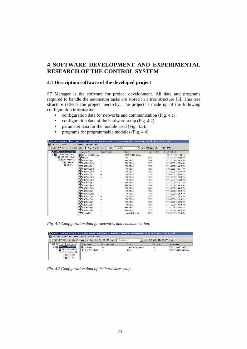
73
4 SOFTWARE DEVELOPMENT AND EXPERIMENTAL RESEARCH OF THE CONTROL SYSTEM
4.1 Description software of the developed project S7 Manager is the software for project development. All data and programs required to handle the automaton tasks are stored in a tree structure [5]. This tree structure reflects the project hierarchy. The project is made up of the following configuration information:
• configuration data for networks and communication (Fig. 4.1); • configuration data of the hardware setup (Fig. 4.2); • parameter data for the module used (Fig. 4.3); • programs for programmable modules (Fig. 4.4).
Fig. 4.1 Configuration data for networks and communication.
Fig. 4.2 Configuration data of the hardware setup.
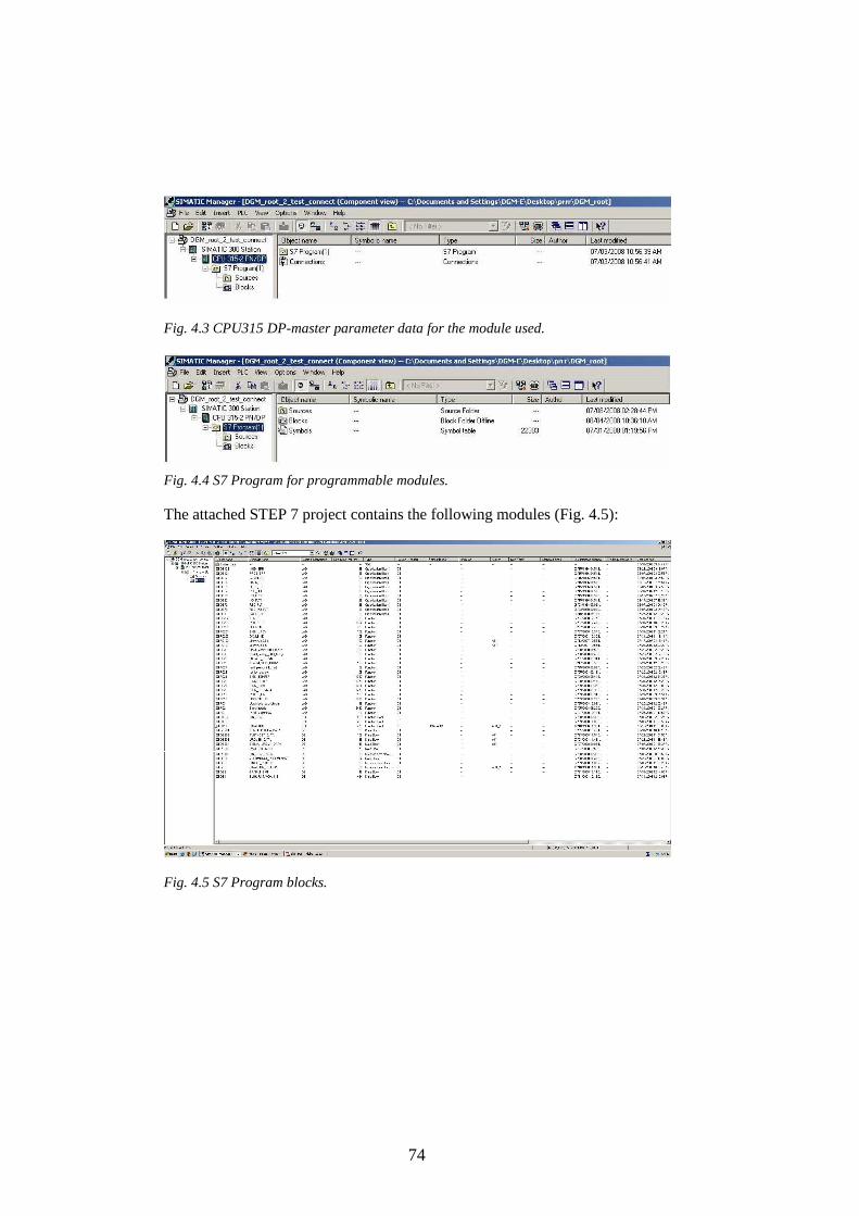
74
Fig. 4.3 CPU315 DP-master parameter data for the module used.
Fig. 4.4 S7 Program for programmable modules. The attached STEP 7 project contains the following modules (Fig. 4.5):
Fig. 4.5 S7 Program blocks.

75
4.2 Control program
4.2.1 Programming considerations. Basic elements of a program A program block is composed of an executable code and comments. The executable code consists of a main program and any subroutines or interrupt routines. The programs have to be designed in a way that will save as much memory space as possible. Program blocks could be created, executed and reloaded online completely independently of each other. The program and data areas are strictly separated. PLC programming becomes more transparent and simpler with the structuring of the program into program blocks and the use of function blocks defined in IEC [STE00]. Subroutines (Function Blocks) are executed only when called by the main program, by an interrupt routine, or by another subroutine. Subroutines are useful because a function is repeatedly executed. Rather than rewriting the logic for each place in the main program where the function occurs, the logic is written once in a subroutine and the subroutine is called as many times as needed during the main program. Subroutines reduce the overall size of a program, decrease the scan time. A subroutine runs in response to a program condition (Fig. 2.19).
Fig. 4.6 Subroutine execution. Interrupt Routines react to specific interrupt events. Whenever the specified event occurs, the PLC executes the interrupt routine. Interrupt routines cause а program to stop immediately, whenever the interrupt is activated, even if the program is in the middle of scanning a net in another subroutine. When the interrupt routine is finished, the program returns to where it was interrupted, and continues from that point until the next Interrupt arrives. Interrupt routines are generally used with
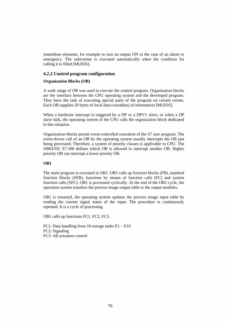
76
immediate elements, for example to turn an output ON in the case of an alarm or emergency. The subroutine is executed automatically when the condition for calling it is filled [MUE05].
4.2.2 Control program configuration
Organization Blocks (OB) A wide range of OB was used to execute the control program. Organization blocks are the interface between the CPU operating system and the developed program. They have the task of executing special parts of the program on certain events. Each OB supplies 20 bytes of local data (variables) of information [MUE05]. When a hardware interrupt is triggered by a DP or a DPV1 slave, or when a DP slave fails, the operating system of the CPU calls the organization block dedicated to this situation. Organization blocks permit event-controlled execution of the S7 user program. The event-driven call of an OB by the operating system usually interrupts the OB just being processed. Therefore, a system of priority classes is applicable to CPU. The SIMATIC S7-300 defines which OB is allowed to interrupt another OB. Higher priority OB can interrupt a lower priority OB. OB1 The main program is executed in OB1. OB1 calls up function blocks (FB), standard function blocks (SFB), functions by means of function calls (FC) and system function calls (SFC). OB1 is processed cyclically. At the end of the OB1 cycle, the operation system transfers the process image output table to the output modules. OB1 is restarted, the operating system updates the process image input table by reading the current signal states of the input. The procedure is continuously repeated. It is a cycle of processing. OB1 calls up functions FC1, FC2, FC3. FC1: Data handling from 10 storage tanks Е1 – Е10 FC2: Signaling FC3: All actuators control

77
Fig. 4.7 The main program structure.

78
Fig. 4.8 OB1 function blocks.
4.2.3 Data handling from ten storage tanks (FC1) Function description The functions FC200 (pressure reading), FC201 (level switch), FC202 (level measurement), FC203 (density calculation), FC204 (temperature data reading) are created with DB200 – DB204. DB200 (Pressure Data Block), pressure _DATA, (PIR_1 – PIR_10) DB201 (Level switch Data Block), level switch _DATA, (LIRA_1 – LIRA_10) DB202 (Level Data Block), level_DATA, (LIR_1_m – LIR_10_m; LIR_1_% – LIR_10_%) DB203 (Density Data Block), density_DATA, (QIR_1_KG_M3 – QIR_10_KG_M3; QIR_1_% – QIR_10_%) DB204 (Temperature Data Block), temperature _DATA, (TIR_1 – TIR_10) DB200–DB 204 data blocks contain the data for the input values (relative to the attached program). The values from DB200 – DB204 are read in by the FC200 – FC204 and calculated. Once all the Data DB values have been processed, the process is repeated automatically. The DB can be any size (within the scope of the CPU data); only the structure has to be maintained.

79
These functions are handled in FC1 and are called in OB1. The calculated values are output as a curve chart on the operator panel. FB101 and Instance Data Block DB6 Two types of data blocks are used in the program: global data blocks and instance data blocks [MUE05]. The mathematical implementation of the linear equation f(x) = m * x + b takes place via Function Block FB101, and its instance Data Block DB6. FB100 uses the data structure to determine how long the corresponding "data DB" is and calculates the individual points on the basis of this. The source file was implemented on the high level language SCL (Fig. 4.9). The instance data block DB6 is permanently assigned to a function block FB101 and contains the local block-specific variable of the FB101. FB101 is called in FC1 for level and density linearization (FC10, FC12). Function blocks (FBs) have a (recall) memory. As DB number is limited, the method allowing using the instance DB for several calls of functional block, FB was used. Data Blocks will be used as HMI Interface for high level automation.
Fig. 4.9 The SCL source file. Temporary variables When blocks are created, temporary variables (TEMP) which are only available during block execution and then overwritten again are declared in all program blocks (OB, FC, FB) [MUE05]. These local data have a fixed length per OB. Local data must be initialized prior to the first read access. Each OB also requires 20 bytes of local data for its start information. Local data access is faster than access to the data in DBs.
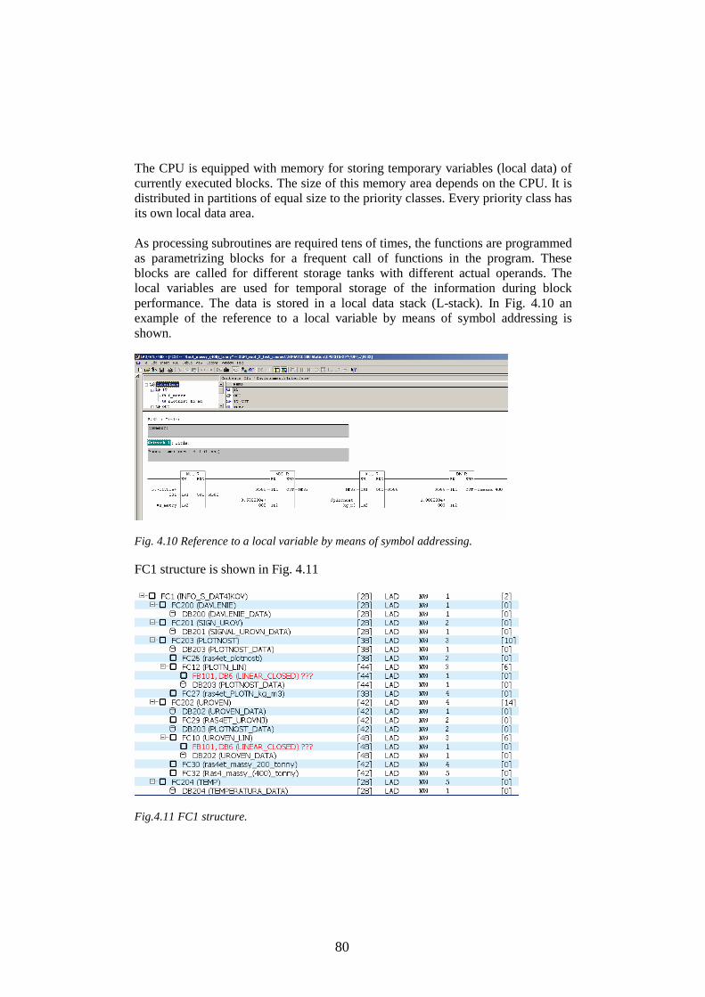
80
The CPU is equipped with memory for storing temporary variables (local data) of currently executed blocks. The size of this memory area depends on the CPU. It is distributed in partitions of equal size to the priority classes. Every priority class has its own local data area. As processing subroutines are required tens of times, the functions are programmed as parametrizing blocks for a frequent call of functions in the program. These blocks are called for different storage tanks with different actual operands. The local variables are used for temporal storage of the information during block performance. The data is stored in a local data stack (L-stack). In Fig. 4.10 an example of the reference to a local variable by means of symbol addressing is shown.
Fig. 4.10 Reference to a local variable by means of symbol addressing. FC1 structure is shown in Fig. 4.11
Fig.4.11 FC1 structure.
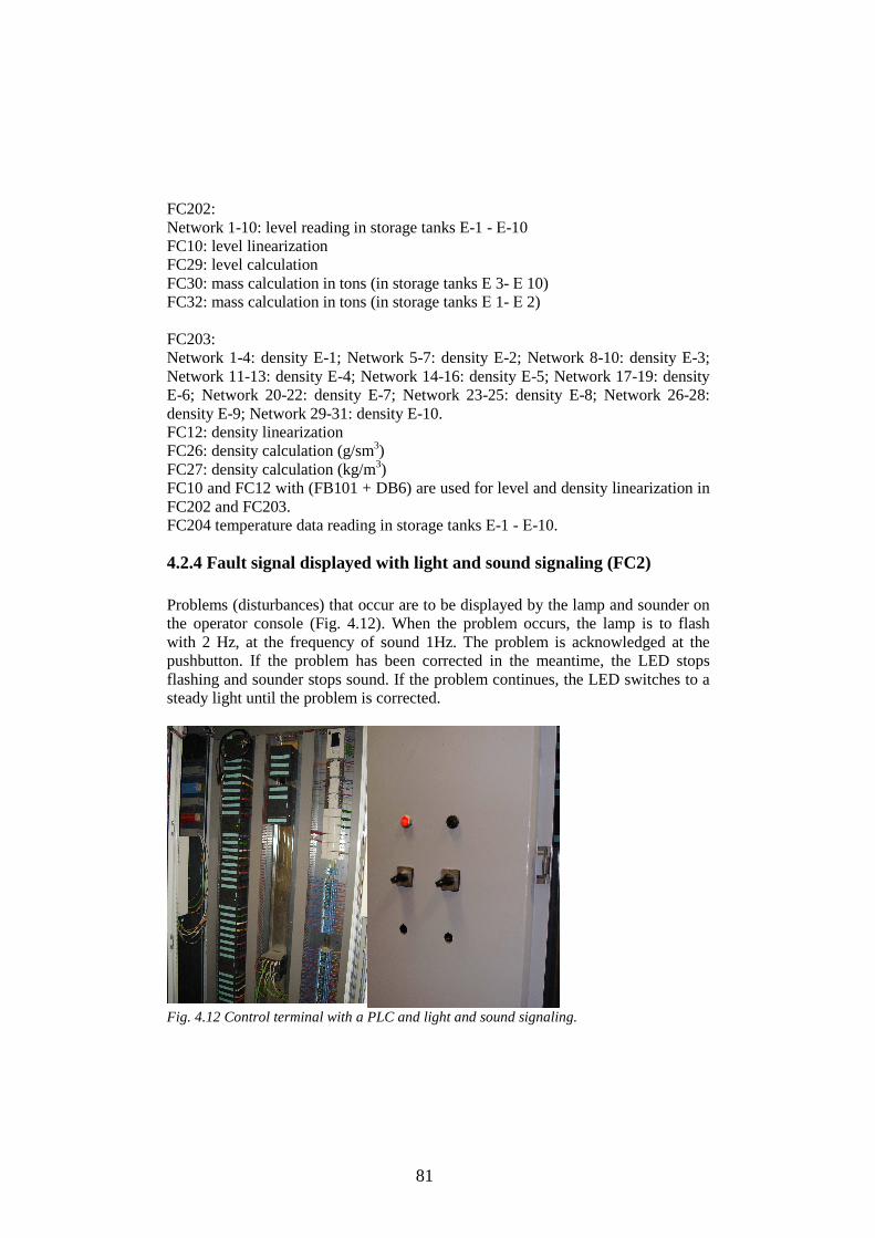
81
FC202: Network 1-10: level reading in storage tanks E-1 - Е-10 FC10: level linearization FC29: level calculation FC30: mass calculation in tons (in storage tanks E 3- Е 10) FC32: mass calculation in tons (in storage tanks Е 1- Е 2) FC203: Network 1-4: density E-1; Network 5-7: density E-2; Network 8-10: density E-3; Network 11-13: density E-4; Network 14-16: density E-5; Network 17-19: density E-6; Network 20-22: density E-7; Network 23-25: density E-8; Network 26-28: density E-9; Network 29-31: density E-10. FC12: density linearization FC26: density calculation (g/sm3) FC27: density calculation (kg/m3) FC10 and FC12 with (FB101 + DB6) are used for level and density linearization in FC202 and FC203. FC204 temperature data reading in storage tanks E-1 - Е-10.
4.2.4 Fault signal displayed with light and sound signaling (FC2) Problems (disturbances) that occur are to be displayed by the lamp and sounder on the operator console (Fig. 4.12). When the problem occurs, the lamp is to flash with 2 Hz, at the frequency of sound 1Hz. The problem is acknowledged at the pushbutton. If the problem has been corrected in the meantime, the LED stops flashing and sounder stops sound. If the problem continues, the LED switches to a steady light until the problem is corrected.
Fig. 4.12 Control terminal with a PLC and light and sound signaling.

82
The FC or FB blocks are programmed as parameter-assignable. Since the fault subroutine is required many times in the system, the FC 9 is only once programmed as a parameter-assignable funcion. The FC 9 is then called many times for the different faults and is assigned a different actual address each time. Flashing frequency memory bit is M10.3 for 2 Hz and M10.2 for 1 Hz. A part of the program is shown in Fig. 4.12. As RLO edge detection of the fault signal is carried out, since the memory would otherwise be immediately reset when an existing problem is acknowledged. If the message has not yet been acknowledged, logic operation causes the LED to flash. With this, the bit memory M10.3 that was defined as a clock memory when parameter assignment was made in the CPU is gated.
Fig. 4.13 Fault signal displayed in the online mode.

83
Structure FC2
Fig. 4.14 Displaying the Program Structure FC2. The following signaling functions have been handled in FC2 (Fig. 4.14). FC22 is the Level signaling function, FC25is the Pressure signaling function, FC27 is the Density signaling function, FC30 is the Temperature signaling function with two data blocks: DB1 (Data Block for the signaling reference values): (PIR_1_MIN - PIR_10_MIN; PIR_1_MAX - PIR_10_MAX;) (LIR_1_MIN - LIR_10_MIN; LIR_1_MAX - LIR_10_MAX;) (QIR_1_MIN - QIR_10_MIN; QIR_1_MAX - QIR_10_MAX;) (TIR_1_MAX - TIR_10_MAX;) DB2 (Data Block of the signaling switching on): (PIR_1_MIN_SR - PIR_10_MIN_SR; PIR_1_MAX_SR - PIR_10_MAX_SR;) (LIR_1_MIN_SR - LIR_10_MIN_SR; LIR_1_MAX_SR - LIR_10_MAX_SR;) (QIR_1_MIN_SR - QIR_10_MIN_SR; QIR_1_MAX_SR - QIR_10_MAX_SR;) (TIR_1_MAX_SR - TIR_10_MAX_SR;) Function Block FB11 was created with its own Instance Data Block DB5: FB11 is Function Block LIMALARM (PID Modular); DB5 is Instance Data Block, LIMALARM CLOSED.
4.2.5 Actuator control (FC3) Conditions for closing (Fig. 4.15): If the actual value is lower than the reference value of openness in %, and the new actual value is lower than the previous value

84
and if this actual value is in the limits from 0 to 100 %, and the button #stop is not pressed, then the valve is closing before the necessary position is achieved. Conditions for opening: If the actual value is higher than the set value of openness in %, and the new value is higher than the previous one and if this actual value is in the limits from 0 to 100 %, and the button #stop is not pressed, then the valve moves to open before the necessary position latch is achieved.
Fig.4.15 Part of the program for valve closing.
4.3 System diagnostics The S7 Software tools for testing, error detection and troubleshooting have the possibilities for monitoring and modifying a controlled process. A fault that was triggered by the faulty functioning of components directly associated with the process control, such as cables to sensors-actuators or by a defect in the sensors-actuators itself. The master PLC has an intelligent diagnostics system. It is integrated in the operating system of the CPU and ordered according to diagnostics-capable modules and runs automatically. The CPU stores (temporarily) errors that occur in the diagnostic buffer and thus enables a fast and targeted error diagnosis by service personnel, even for sporadically occurring errors. Modules with diagnostics capabilities can trigger a diagnostic interrupt - if the appropriate parameter settings have been made. The CPU then interrupts execution of the main program and calls the diagnostic interrupt organization block. The start information of this OB contains the module that triggered the interrupt and the diagnostic information from the module itself in 4 bytes. These data are used to generate a message, for example. In cases of modules that can supply more diagnostic information, for example, distributed I/O slave stations, a system function is used to read out the additional diagnostic information [RUB08].

85
Fig. 4.16 Module Information. The Module Information function reads the most important data from the directly connected module. This function describes the module hardware and version, all diagnostic events in the order they occurred, size and usage of different types of the load memory, the longest, the shortest, and the current cycle time. The diagnostic buffer contains all diagnostic events and cannot be deleted by a memory reset (Fig. 4.16). The system function (SFC) is used to write a user entry in the diagnostic buffer and to send it as a message to all the stations that are logged in on the network.
4.3.1 Diagnostic interrupt blocks When a hardware interrupt is triggered by a DP or a DPV1 slave, or when a DP slave fails, the operating system of the CPU calls the organization block dedicated to this situation. Organization blocks permit event-controlled execution of the developed program. The event-driven call of an OB by the operating system usually interrupts the OB just being processed. Therefore, a system of priority classes is applicable to the CPU. The SIMATIC S7-300 defines which OB is allowed to interrupt another OB. Higher priority OB can interrupt lower priority OB. OB1 can be interrupted by OB80–OB87. OB82 is triggered when a DP slave with a diagnostic capability detects an error. The diagnostic alarm is defined in parameters set for the DP slave using the HW Config program. The ОВ86-ОВ87 organization blocks are called when an interface error occurs (MPI network, PROFIBUS DP) or disappears, when an I/O access error occurs, a

86
module rack failure (power failure, interrupted line, defective interface), or a failure of a subnet or a station of the distributed I/O. OB122 is the block for handling the I/O access error with the higher priority (Fig. 4.17). The operating system calls OB122 when the program attempts to gain access to an input-output or a non-exist or a defective DP slave. If OB122 is not programmed, the CPU reacts to such an I-O access error by switching to the stop state [RUB08].
Fig. 4.17 Interpreting error messages in the diagnostic buffer.
4.3.2 DP/DP Diagnostics by means of the program Slave diagnosis is performed in accordance with IEC 61784-1:2002 Ed1 CP 3/1. It can be read out with STEP 7. In STEP 7, the diagnostic frames of the underlying DP slaves can be displayed in the online view of the HW Config - Diagnosing hardware. This example describes the structure of the DP/DP Coupler diagnostics system to illustrate the evaluation of a diagnostic frame. Call of the SFC 13 To read the diagnostic data of the DP/DP Coupler, SFC 13 (DPNRM_DG) is called in OB 1. CALL SFC 13 REQ :=TRUE //Request to read the diagnostic data LADDR :=W#16#3FE //Diagnostics address RET_VAL :=MW0 //RET_VAL of SFC 13
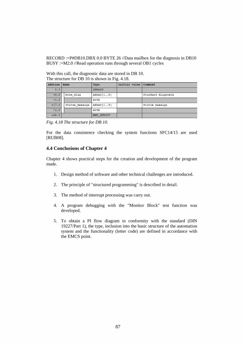
87
RECORD :=P#DB10.DBX 0.0 BYTE 26 //Data mailbox for the diagnosis in DB10 BUSY :=M2.0 //Read operation runs through several OB1 cycles With this call, the diagnostic data are stored in DB 10. The structure for DB 10 is shown in Fig. 4.18.
Fig. 4.18 The structure for DB 10. For the data consistence checking the system functions SFC14/15 are used [RUB08]. 4.4 Conclusions of Chapter 4 Chapter 4 shows practical steps for the creation and development of the program made.
1. Design method of software and other technical challenges are introduced. 2. The principle of "structured programming" is described in detail. 3. The method of interrupt processing was carry out. 4. A program debugging with the "Monitor Block" test function was
developed.
5. To obtain a PI flow diagram in conformity with the standard (DIN 19227/Part 1), the type, inclusion into the basic structure of the automation system and the functionality (letter code) are defined in accordance with the EMCS point.

88
5 SUMMARY This thesis covers the study of theoretical and applied problems of the digital control of the continuous processes by means of programmable logic controllers. . The findings in terms of theory are as follows.
The analysis focused on various PLC technical and software opportunities of general PLC operations, programming for a PLC-based system, I/O addressing for control systems projecting. Procedure of the control system construction is provided with the analysis of its characteristics. Solutions for metering of various parameters at lower energy consumption are supported by examples of innovative measurement technologies. The structure of the control program of the DGO storage tanks park was created and developed. The local control algorithms were developed and tested. Standard programming languages for the development of control algorithms allow the programs to be applied for any type of controllers with integrated MPI/DP interface, a medium program memory and quantity framework, high processing performance in binary and floating-point arithmetic. The control algorithm presented has been developed and applied at Viru Chemistry Group Ltd. This company needs to maximize their assets and ensure complete efficiency to be leveraged from their operations and infrastructure. Practical point of view This research considers how to achieve quick and effective design and implementation of a powerful controller to remote operations, adverse environmental conditions and demanding product requirements. This study is focused on a generic language development which can be easily utilized for an interface between a PLC and any existing tools. Within a process automation system, reliable, effective communication between the field devices and the control system is critical for optimum process control. Thus, consistent bus communication throughout Ex zones, based on PROFIBUS-PA, was realized.
The results of this thesis are being used to construct the control system of the technological processes and the devices functioning in the conditions of the hard industrial environment at an enterprise of the shale-chemical industry. The practical
89
importance of the presented control algorithms was verified by the works performed at Viru Chemistry Group Ltd in the North- Eeast of Estonia.
Owing to this thesis, many advantages of the theoretical and applied problems of the digital control of the continuous processes have been clarified and fully comprehended. An algorithm design can be connected with system design. All applications and subapplications can be separated so easily for debugging. The system diagnostics is able to find out where the mistake is by testing from small application to larger application and then the whole application. The current and future work is connected with further high level DGO storage tank park automation. The control system created allows debugging the control programs for different conditions in hazardous areas. Monitoring of the control system is being created now by means of TRACE MODE SCADA. The main objective of this thesis was to investigate the theoretical and applied problems at control system design with a PLC: implementability, reliability and performance. It has been successfully achieved.
90
6 REFERENCES
[ADV08] Advance, Magazine advance. April 2/2008, http://www.automation.siemens.com/download/internet/cache/3/1468416/pub/de/AdvanceProdNews_E.pdf, April, 2008 [AST97] Åström K. J., Wittenmark B.: Computer Controlled Systems - Theory and Design (3rd ed.), Prentice-Hall, 1997 [BAT93] Batison Robert N. Introduction to Control System Tehnology. 5-ed Prentice Hall, 1993, p.670 [BER02] Berge, J. Fieldbus for Process Control: Engineering, Operation and Maintenance, ISA Press, 2002, p. 232 [BOL03] Bolton W. Programmable Logic Controllers.Third Edition, Newnes, 2003, p. 240 [BERG06] Berger Hans. Automating with SIMATIC. 3rd edition, 2006, I SBN-13:978-3-89578-276-3, p. 220 [BES07] Беспалов А. В., Харитонов Н.И. Системы управления химико-технологическими процессами. Москва, Академкнига, 2007, p. 690 [BUC06] Buckbee George. The Six Myths of Process Control. http://www.expertune.com/, May–October, 2006 [CHI96] Chienskey, F. Greg. Process Control System – Application, Design, and Tuning. 4th edition, New York McGraw-Hill, 1996, p. 382 [CLE96] Clements-Jewery K., W. Jeffcoat The PLC workbook. Prentice Hall, 1996, p.195 [CON96] Connel Bob Process Instrumentation Applications Manual. McGraw-Hill Book Co., 1996, pp. 212-213. [DOR02] Dorf Richard, Bishop Robert. Modern Control Systems. 832 ISBN 5-93208-119-8, 2002, p. 831 [DEN06] Денисенко Виктор. Заземление в системах промышленной автоматизаци. СТА 3, 2006, p.76 – 92 [FRE07] Electromagnetic Compatibility Qualification and Analysis of

91
Microcontrollers. (100 kHz – 1 GHz) Test Methods and Procedures, http://freescale.com. 10.07.07 [FRI01] Fiori, F.; Musolino, F. Analysis of EME produced by a microcontroller operation. Design, Automation and Test in Europe, 2001, Conference and Exhibition, 2001, Proceedings Volume, Issue, 2001. Page(s): 341 – 345, Digital Object Identifier 10.1109/DATE.2001.915047 [GER03] Германов Александр. Принцип обеспечения электросовместимости измерительных приборов. СТА 4, 2003, p. 64 – 72 [HAS06] Hassapis G. Implementation of predictive control algorithms on networked control systems. American Control Conference 2006, JUN 14-16, 2006, 2006 American Control Conference, VOLS 1-12, p.1936-1941, 2006 [GDA02] Жданкин Виктор. Защита приборов и средств автоматизайции от высоковольтных импульсов напряжения, СТА 4, 2002, p.66 – 72 [GDА08] Жданкин Виктор. Модульные взрывозащищённые системы удалённого ввода/вывода для установки во взрывоопасных зонах. СТА 3-4, 2008, p.6 – 12 [JEE05] Jee E., Yoo J., Cha S. Control and data flow testing on function block diagrams. 24th International Conference on Computer Safety, Reliability and Security, SEP 28-30, 2005. Computer Safety, Reliability and Security, Proceedings, p. 67-80, 2005 [JIA06] Jiang JB, Kaigala GV, Backhouse CJ, et al. Modeling and controller design of a nonlinear time-varying thermal device in a microfluidic platform. American Control Conference 2006, JUN 14-16, 2006. 2006 American Control Conference, VOLS 1-12, 2006 [ING06] Инжиниринг электроприводов и сситем автоматизации. Под редакцией Новикова В.А., Москва, Академия, 2006, p. 367 [INT08] Intelli+intelligent command. http://www.bernard-actuators.com/imgs/documentation/a116_03.pdf, April, 2008 [LEV07] Levant, J.-L., Ramdani, M., Perdriau, R., Drissi, M. EMC Assessment at Chip and PCB Level: Use of the ICEM Model for Jitter Analysis in an Integrated PLL. Electromagnetic Compatibility, IEEE Transactions on Volume 49, Issue 1, Feb. 2007 Page(s): 182 – 191

92
[LUY90] Luyben, William. Process Modeling, Simulation and Control for Chemical Engineers. 2nd edition, New York, McGraw-Hill, 1990, p.360 [MIT01] Mitsubishi FX2N Series Programmable Controllers hardware manual. 2001 [MUE05] Mueller J. Controlling with Simatic. ISBN 3-89578-255-6, 2005, p. 162 [NIS00] Nise Norman S. Control Systems Engineering. 3rd ed., ISBN 0-471-36601-3, 2000, p. 970 [PAR03] Parr. E. A. Programmable Controllers An Engineers Guide. Third edition, Newnes, 2003, p. 430
[REM08] Remote I/O for Vision PLCs. http://www.unitronics.com/Content.aspx?Page=News&Id=117, May,15,2008 [RUB06] Ruban Olga, Laugis Juhan PLC and Control Systems. International conference” Electrical and Control Technologies-2006”, Selected papers of the International conference, 4-5 May 2006, Kaunas, Lithuania (Kaunas University of Technology), edited: A. Navickas (general editor), A. Sauhats, A. Virbalis, V. Ažubalis, A. Lipnickas. UDK 621.3 (474.5) (06); 681.5(474.5) (06). Kaunas University of Technology, 2006, p. 255 – 260 [RUB07] Ruban Olga. Tuning Problems for Closed-Loop Systems Optimization. Ninth International Scientific Conference “Smolyan-2007”, 23-24 June. Bulgaria. Smolyan, 2007, p. 209 – 218 [RUB08] Ruban Olga, Laugis Juhan Troubleshooting and Debugging Tools. 5th International Symposium “Topical Problems of Education in the Field of Electrical and Power Engineering. ISBN 978-9985-69-0046-8, Kuressaare, Estonia, January 14 – 19, 2008, p. 216-221 [STE00] Steven W. Smith J. Quevedo and T. Escobet, Ed., Digital Control 2000: Past, Present and Future of Control. IFAC Proceedings Volumes, New York: Pergamon, 2000, p.180 [WEB03] Webb John W., Reis A. Programmable Logic Controllers. Newnes, 2003, p.250 [WEI03] Weigmann Josef, Kilian Gerhard. Decentralization with PROFIBUS DP/DPV1. 2003, ISBN 3-89578-218-1, p.251 [ZAN06] Zanki Arnold. Milestones in automation. ISBN 3-89578-259-9, 2006, p. 247

93
[ISO 11064] ISO 11064-7. Ergonomic design of control centers. Part 7: Principles for the evaluation of control centers. http://www.iso.org/iso/iso_catalogue [IEC 61096] IEC 61096-х. Industrial-process measurement and control - Evaluation of system properties for the purpose of system assessment. http://www.iec.ch/ [IEC 60079] IEC 60079-27. Design and implementation of intrinsically safe fieldbus networks in hazardous areas. http://www.iec.ch/ [IEC 61131] IEC 61131. Programmable controllers. http://www.iec.ch/ [IEC 61508] IEC 61508. Part 2: Requirements for electrical/electronic/programmable electronic safety-related systems. Part 3: Software requirements. Part 4: Functional safety of electrical/electronic/programmable electronic safety-related systems. http://www.iec.ch/ [IEC 61499] IEC 61499. Distributed Function Block Architecture for Industrial Measurement and Control Systems (IPMCS). http://www.iec.ch/ [EN 50019] DIN EN 50019. Electrical apparatus for potentially explosive atmospheres – increased safety ‘e’. http://www.standardsdirect.org/standards/ [EN 50020] DIN EN 50020. Electrical apparatus for potentially explosive atmospheres – intrinsic safety ‘i’. http://www.standardsdirect.org/standards/ [IEC 62305] IEC 62305. Lightning Protection. http://www.iec.ch/

94
ABSTRACT
The thesis covers research, development and application of a PLC for control systems design. The study is dedicated to the solution of scientific problems related to creation of a new control system DGO storage tank park with a high level reliability.
Thematic topicality is explained by the practical needs - in an effective, ergonomic, and safe control system for temporal storage of the oil distillation production at a Viru Chemistry Group Ltd. The study is based on novel theoretical findings and progressive technologies in the field of sensors and driving engineering, information technologies, and control developed in recently in the European Union and particularly in Estonia.
Studies focused on theoretical and applied problems of the digital control of the continuous processes by means of programmable logic controllers. Concepts of the control system construction in the hard environment conditions are presented. Its hardware and configuration were analyzed. As a result, the problem of control algorithm development has been solved. The development of the algorithms of measurement and control will enable one to easily link different systems of intelligent devices with one another over networks and implement expansions. This not only reduces the number of interfaces, but also ensures maximum data transparency across all levels – from the field, through the production level to the management level. The thesis consists of four chapters. Chapter 1 is devoted to research of theoretical and applied problems of the digital control of the continuous processes by means of programmable logic controllers. Chapter 2 is dedicated to the development of a novel method of PLC control and the distributed I/O synthesis. Chapter 3 describes the design method for an explosion protected system. The final chapter focuses on the control program configuration and experimental research.

95
LÜHIKOKKUVÕTE (ANNOTATSIOON) Antud doktoritöös uuritakse programmeeritavate kontrollerite (PLC) pidevate protsesside digitaalse juhtimise teoreetilisi ja praktilisi küsimusi. Töö eesmärgiks on DGÕ mahutite pargi automaatiseerimiseks uute tehniliste ja tarkvaraliste lahenduste loomine. Töö teema on aktuaalne seoses efektiivse, ergonoomilise ning ohutu põlevkivikeemia tootmise arendamisega. Uuringud on läbi viidud uute teoreetiliste tulemuste ja moodsa tehnoloogia baasil elektriajamite, andurite ja mikroprotsessrorite valdkonnas, mida on viimastel aastatel arendatud nii Euroopa Liidus kui ka Eestis. On läbi viidud erinevate kontrollerite tehniliste ja tarkvaraliste võimaluste analüüs juhtimissüsteemide projekteerimise hajutatud sisendite/väljunditega. Juhtimistarkvara PLC juhtimissüsteemi jaoks on arendanud autori poolt ja lubatud kasutada Viru Keemia Grupp AS-is. Kõik kirjutatud PLC programmid on üldised. Arendatud tarkvara võib olla kohandatud ja rakendatud programmeeritavate kontrollerite kõikide mudelite jaoks.
Antud ja tulevane töö on seotud DGÕ mahutite pargi automatiseerimisega Eesti ühes suuremas ettevõttes, Viru Keemia Grupp AS-is. Selle töö põhieesmärk on PLC juhtimisprotsessi teoreetiliste ja praktiliste küsimuste uurimine nagu realiseeritavus, töökindlus ja täitmine, mis oli edukalt saavutatud. Doktoritöö koosneb neljast peatükist. Esimeses uuritakse olemasolevate programmeeritavate kontrollerite võimalusi lahendada juhtimisprobleeme programmeerimismeetodiga. Teises vaadeltakse juhtimissüsteemi struktuuri sünteesi kasutades programmeeritavaid kontrollereid, hajutatuid I/O ja detsentraliseerituid mooduleid. Kolmandas peatükis kirjeldatakse juhtimissüsteemi projekteerimismetoodikat. Viimases peatükis uuritakse arendanud juhtimistarkvara PLC juhtimissüsteemi jaoks.

96
PUBLICATIONS 1. Juhan Laugis, Olga Ruban Vocational Education in the field of Electrical Engineering and Automatic in Estonia. Automation and control technologies 2004". Proceedings of the International Conference. Kaunas University of Technology, 2004, p. 38-42. 2. Olga Ruban, Juhan Laugis Technology of studying of a Subject Power Electronics at Automatic System Training. 2nd International Symposium “Topical Problems of Education in the Field of Electrical and Power Engineering. Kuressaare, Estonia, January 17 – 22, 2005, p. 67-72, ISBN 9985-69-033-8. 3. Olga Ruban, Juhan Laugis Automatic Flow-Through Control with PI and PID controllers. 3rd International Symposium Topical Problems of Education in the Field of Electrical and Power Engineering. ISBN 978-9985-69-0036-2 Kuressaare, Estonia, January 16–21, 2006, p. 106-111 4. Olga Ruban, Juhan Laugis PLC and Closed-Control Systems. International conference” Electrical and Control Technologies”, 4-5 May 2006, Kaunas, Lithuania, p. 504 - 509.
5. Olga Ruban, Juhan Laugis PLC and Control Systems. International conference” Electrical and Control Technologies-2006”. Selected papers of the International conference, 4-5 May 2006, Kaunas, Lithuania (Kaunas University of Technology), edited: A. Navickas (general editor), A. Sauhats, A. Virbalis, V. Ažubalis, A. Lipnickas. Kaunas University of Technology, 2006, p. 255 – 260, UDK 621.3 (474.5)(06); 681.5(474.5)(06).
6. Olga Ruban, Juhan Laugis Some Aspects of Closed Control Loop Design. 4th International Symposium Topical Problems of Education in the Field of Electrical and Power Engineering. January 15–20, 2007, Kuressaare, Estonia, p.118-122, ISBN 978-9985-69-041-3. 7. Olga Ruban Teaching technology in the Field of Power Engineering and Automation in Estonia. 14th International Scientific-Technical Conference «Alternating Current Electrical Drive ACED 2007», Ekaterinburg, 13 – 16 march 2007. ISBN 978-5-321-01025-9, p. 307-311. 8. Olga Ruban, Juhan Laugis Signal Filters Using in the PID Loops. 2nd International Conference "Automation and control technologies ECT - 2007", 2007, Kaunas. Proceeding of the 2nd International Conference on Electrical and Control Technologies, 3-4 May 2007, Kaunas, Lithuania (Kaunas University of Technology), edited: A. Navickas (general editor), A. Sauhats, A. Virbalis, V. Ažubalis. Kaunas University of Technology, 2007, p. 45 – 49, ISSN 1822-5934.

97
9. Olga Ruban Tuning Problems for Closed-Loop Systems Optimization. Ninth International Scientific Conference “Smolyan-2007”, 23-24 June, Bulgaria, Smolyan, 2007, p. 209 – 218. 10. Olga Ruban, Juhan Laugis Troubleshooting and Debugging Tools. 5th International Symposium “Topical Problems of Education in the Field of Electrical and Power Engineering. Kuressaare, Estonia. January 14 – 19, 2008, p. 216-221, ISBN 978-9985-69-0046-8.
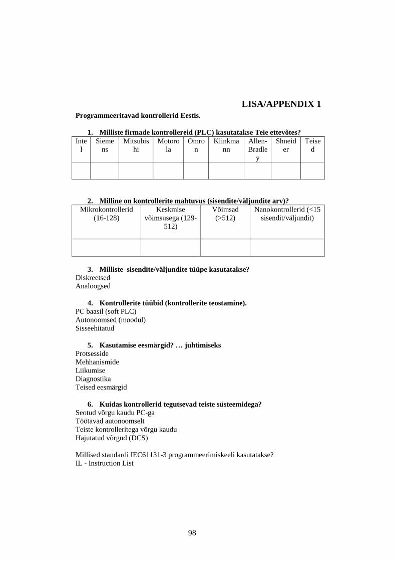
98
LISA/APPENDIX 1 Programmeeritavad kontrollerid Eestis.
1. Milliste firmade kontrollereid (PLC) kasutatakse Teie ettevõtes? Inte
l Sieme
ns Mitsubis
hi Motoro
la Omro
n Klinkma
nn Allen-Bradle
y
Shneider
Teised
2. Мilline on kontrollerite mahtuvus (sisendite/väljundite arv)? Mikrokontrollerid
(16-128)
Keskmise võimsusega (129-
512)
Võimsad (>512)
Nanokontrollerid (<15 sisendit/väljundit)
3. Milliste sisendite/väljundite tüüpe kasutatakse?
Diskreetsed Analoogsed
4. Kontrollerite tüübid (kontrollerite teostamine). РС baasil (soft PLC) Autonoomsed (moodul) Sisseehitatud
5. Kasutamise eesmärgid? … juhtimiseks
Protsesside Mehhanismide Liikumise Diagnostika Teised eesmärgid
6. Kuidas kontrollerid tegutsevad teiste süsteemidega?
Seotud võrgu kaudu РС-ga Töötavad autonoomselt Teiste kontrolleritega võrgu kaudu Hajutatud võrgud (DCS) Millised standardi IEC61131-3 programmeerimiskeeli kasutatakse? IL - Instruction List

99
ST - Structured Text LD - Ladder Diagram FBD - Function Block Diagram SFC - Sequential Function Chart
7. Kui kavatsete juhtida protsesse tulevikus, siis milliseid? Diskreetseid Pidevaid

100
APPENDIX 2 PLC IN EDUCATION The scope of this part is to present the hardware/software infrastructure designed to interface an industrial PLC to a laboratory process simulator and to a real small scale plant, in order to validate the industrial PLC software control code before the real plant commissioning phase. The idea was to create a real control system model which includes
• the controlled system with different characteristics, • the controller with the expansion modules, • sensors of different types for measurement of the investigated parameter • communication with the controlled object and the top level of automation.
The laboratory is intended for training the students on the cycle of the systems engineering. The need for systems engineering arose with the increase in the complexity of systems and projects. At the same time, a system can become more complex due to an increase in size as well as with an increase in the amount of data, variables, or the number of fields that are involved in the design. The development of smarter control algorithms, microprocessor design, and analysis of environmental systems also come within the purview of systems engineering. Systems engineering encourages the use of tools and methods to better comprehend and manage complexity in systems. Some examples of these tools can be seen here. The purpose of this laboratory is to give insight into elementary concepts and principles in automatic control with PLCs. The students also get acquainted closer with the PID controller, the industrially most commonly occurring controller. A PID controller is implemented in a PLC by means of a program. Six working places that consist of the real controlled system models, the controller, the expansion modules, and the corresponding sensors were created. The system structure is a single-loop control system that includes a SISO process, a SISO controller, and a feedback loop. Each place has the SCADA system WinCC license. The laboratory can be used by the students for their research (the course and diploma projects). Except for training students, it is intended for re-training and consulting the personnel from the enterprises of the North-East.

101
PLC control system SIMATIC S7-200 series PLCs S7 224 and S7 226 DC/DC/DC were adopted to realize the logic, range control and protection of promoting systems. The PLCs get contact with the computers through a RS485 Serial-port. Basic structure for experimental process analysis The main points and problems of an experimental process analysis consist of the formulation of requirements demanded of the model (application aim, accuracy, validity range), the preparation and implementation of the experiments, the selection of suitable methods for the analysis of the process data, error estimation and model verification. As part of a stage of the experiment, the auxiliary hardware and software devices, the model structure (e.g. in the form of qualitative information regarding the process behaviour), the main process the disturbance variables, the required measuring time are considered. The hardware and metrology preparations include the assembly of suitable control, measuring and recording techniques, unless already available on the process and the verification of the experimental techniques/technology under operating conditions. The most common architecture is a PLC to do the real-time control, different controlled systems, and TD or SCADA system as the operator interface for data monitoring. The control techniques investigated here are used for process control. Regarding communication between a controller and a process The function operation of closed-loop control can be explained and demonstrated using a model of the real automatic control loop. This model consists of technical devices. The existence of an exact model for this system allows a significant reduction of experiments and effort made for tuning and testing of this system. In contrast to the widespread simulated control loops, the following experiments investigate real control loops with calculations based on obtained parameters.
The first step of the experimental analysis is the investigation of the available technical resources. These comprise the sensors and actuators of the process to be examined and the auxiliary hardware and software equipment required for data acquisition and evaluation.

102
For visualization, the SCADA environment Citect has been chosen. Data exchange between the controller S7-200 and Citect SCADA is completed with protocol SPPI - direct connection of a point-point type. To open the created project in Citect Explorer it is necessary to make a connection between the controller and SCADA. The auxiliary interfaces are needed for communication between the controller S7 CPU226 and Citect SCADA. • OPC server - PC Access • Matriсon OPC Explorer
Fig.1 Block diagram of the controller connection. Preparations Basic knowledge of automation and control engineering is required on the course. Terms such as, transfer function, PID-control, analog and digital I/O should be somewhat familiar to the student attending the course. To get out as much as possible of the lab the students have to know the following concepts: • open and closed loop system • block diagram • reference value, process output, control signal • stationary error The students also have to read through lab manuals, including the appendix on the user interface. 1 Experiment-based fundamentals of automation systems 1.1 Temperature controller project The temperature controlled system permits the investigation of continuous and discontinuous control loops. Controller performance can be analyzed via connectable disturbance variables. In this setup, the wide range of analysis tools enable optimized parameterization of the controller.
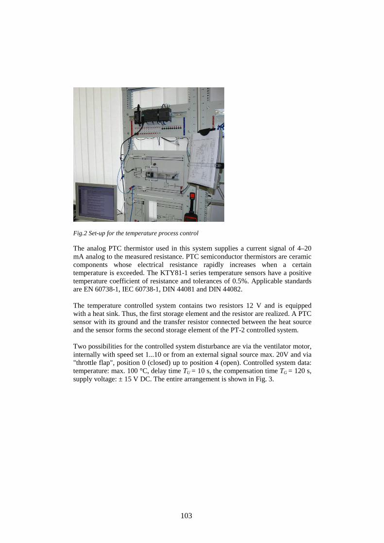
103
Fig.2 Set-up for the temperature process control The analog PTC thermistor used in this system supplies a current signal of 4–20 mA analog to the measured resistance. PTC semiconductor thermistors are ceramic components whose electrical resistance rapidly increases when a certain temperature is exceeded. The KTY81-1 series temperature sensors have a positive temperature coefficient of resistance and tolerances of 0.5%. Applicable standards are EN 60738-1, IEC 60738-1, DIN 44081 and DIN 44082. The temperature controlled system contains two resistors 12 V and is equipped with a heat sink. Thus, the first storage element and the resistor are realized. A PTC sensor with its ground and the transfer resistor connected between the heat source and the sensor forms the second storage element of the PT-2 controlled system. Two possibilities for the controlled system disturbance are via the ventilator motor, internally with speed set 1...10 or from an external signal source max. 20V and via "throttle flap", position 0 (closed) up to position 4 (open). Controlled system data: temperature: max. 100 °C, delay time TU = 10 s, the compensation time TG = 120 s, supply voltage: ± 15 V DC. The entire arrangement is shown in Fig. 3.

104
Fig. 3 The temperature controlled system. Unipolar heat source (max. 20 W for 20 V) with a temperature sensor, a thermal protection switch, a ventilator motor and a "throttle flap", built into a transparent air channel. Controlled system output signal (process variable) switchable to 2 mA/10 °C or 1 V/10°C as desired. Siemens S7 224 DC/DC/DC with the EM235 4AI/1AO expansion module is used to control the temperature process. Analog module EM235 converts the temperature into the digital value that can be processed in the CPU PLC and it converts the digital value into an analog manipulated variable MV. The Set point and the process variable are given in the same type of units (degrees Celsius) with 0.1° resolution. Expansion module enables connecting PLCs directly to the temperature sensor. For EM 235 Unipolar (because it is configured like this - for unipolar range 0 to 10 V – the corresponding configuration of switches was chosen. Voltage is used so there is no offset. The process gives back the signal, where 1 V = 10°C. The control objective for the controller is to produce an output MV to force the process variable PV to track the given trajectory of its set point SP under variations of the set point, disturbances, and process dynamics. The PV is based on an analogue input using current or voltage, therefore the analogue range units are used to set the PV low and PV high limits. The setpoint is 'normalized' to this range. The data format is "left justified" in the analogue word, 15-th bit it is a sign bit (the zero specifies a positive word meaning data). The range of a possible measured signal of a range 0 - 20mA will be transformed to a range of integers from 0-32000. Step 7 uses the input signals in the WORD format. The output of the temperature controlled system is connected to the PLC input AIW0.

105
The program structure The set point is predetermined and will be entered directly into the loop table. The process variable will be supplied as a unipolar, analogue value from the measurement. The loop output will be written to a unipolar, analogue output which is used to control the heater. The span of both the analogue input and analog output is 32000. Only proportional and integral control will be employed in this example. The PV is AIW0 and the output was assigned as AQW0 (the PV and the SP are the normalizing values). The output signal necessary to control the heating is 0-10V. If heating needs a 0-10V signal, then the scaling is a Unipolar signal. The size of the process time constant Tp determines the maximum desirable loop sample time TS. The speed of control is determined by the PID values. Analog input and output values of the expansion modules EM 231, EM 232 and EM 235, as well as of CPU 226 are displayed digitally in the INTEGER data word format. It is necessary to make conversions to ensure correct interpretation and processing. The PID0_INIT Subroutine is connected in the network through SM0.0 bit. A VD100 was put in the Data Block table (SP value on the PID0_INIT). After conversion the signal is entered in the register for transfer to the basic program, and is also written in the register Data Block for using by the text display TD200. If the signal level exceeds the maximal value (an integer 32000), it will be equalled to 10 V. When the PV is within this range, the PID function is active. After the program loading to the controller and its translation in the Run Mode, there is an opportunity to supervise the program execution by means of Program Status from the control panel. Active signals are displayed by dark blue colour. Contents and bits of counters, comparators, and timers are deduced on the working panel. One of the goals was to develop simple tuning rules that can be employed for both manual tuning and automatic tuning for the process [RUB07]. The techniques for automatic tuning of PID controllers are discussed in [RUB06]. Automatic tuning of PID controllers can be realized by joining the methods for obtaining process dynamics. The author uses several adaptive approaches, including gain scheduling, automatic tuning, and continuous adaptation. The system responsiveness to state changes is determined by its time constant. Temperature system is very slow. Problems of slow controlled systems: the quiescent value is only reached after about 4-5 compensation times. This makes the empirical correction of the control loop virtually impossible. The determination of

106
the system data and the advance determination of controller settings are accomplished using the setting criteria of Åström and Hägglund [AST97]. The loop gain and time constants have been determined from engineering calculations and may be adjusted as required to achieve optimum control. For a given control loop the values KP and TV, can be determined as functions of the controlled system parameters. A PLC-based control system implements the adaptive logic. This is because the tuning values must be programmed as a look-up table (or schedule) where the measured PV indicates the current level of operation, and as such, "points" to appropriate controller tuning values in the table at any moment in time. Once online, the PLC reads a set of tuning values from the table, as indicated by the current value of the PV. These are downloaded into the controller algorithm, which then proceeds to calculate the next controller output (MV) value. Tuning updates are downloaded into the controller every loop sample time TS. As a result, the controller continually adapts as the operating level changes to maintain a reasonably consistent control performance across a range of nonlinear behavior. Sample Time TS parameter defines the intervals between PID function updates. Two operation modes are provided -”automatic” and “manual”. The mode is selected using a digital input (I0.0). The changeover between the operation modes is to be realized without shutting down the actuator. Tuning parameters are determined as functions of the system parameters of the controlled system. The calculated values of the time constants are: KP = 6 TI (Integral time) = 0.45 min. = 27 s TD (Derivative time) = 0 Tuning parameters determined by auto-tuning: KP = 5.567033 TI (Integral time) = 0.6469359 min = 38 s TD (Derivative time) = 0 The experimental results show highly desirable performance of this closed-loop.

107
Fig. 4 Results of auto-tuning. The following experiments are carried out: 1. Temperature recording in the S7-200 by means of Pt100 and SITRANS Measuring Transducer 2. Temperature Measurements with Special Input Modules: • Resistance Temperature Detector (RTD) Input Module
• Thermocouple/Millivolt Input Module 3. Temperature control with S7-200 PID controller 4. Programming with a SCADA /HMI- Software 1. 2 Experiments with the liquid controlled system In this project, students use a liquid level measurement to maintain a pre-specified filling level with a control circuit. In this setup, the filling level and the flow-rate are controlled by the S7-200 PLC. Both the filling level and flow rate can be measured from a single device. 1.2.1 Set-up for control a level filling process Sonar-BERO with the shortest sensing range (300 mm) provides the distance detection using ultrasound technology, and conversion into a frequency signal that is proportional to distance. The accuracy of Sonar-BERO is +/-1.5% of the nominal value.
The ultrasonic measuring transducer provides a current (4-20 mA) at the input of the analog input module. The current is proportional to the fill level in the container.

108
The analog module EM 235 must be calibrated so that the analog value of 20 mA is converted into the digital value of 32000 at a max fill level. At a fill level of 0 the analog value of 4 mA is converted into the value 6400. The program scales the converted digital values as height in cm.
The voltage for the fill level indicator must be produced via the analog output module. This voltage is generated by writing the corresponding digital value to the analog output word (AQW0).
The analog output module transfers the fill level height to a measuring instrument in the form of a voltage of between 0 V and 10 V. The analog display of the measuring instrument reacts to the voltage with needle deflection proportional to the fill level.
The formula scales every value between a maximum and minimum scaling value. This program receives the analog input value (AIW0) and scales it for the analog output module.
First the program reads the AIW0, a value between 4 mA and 20 mA (6400 and 32000), and scales the value to a normalized value between 0.0 and 1.0. This value is then scaled for the ranges of 0.0 to 100.0 and 0 to 32000.
1.2.2 The liquid controlled system The liquid level controlled system is a model used in instrumentation and automatic control engineering for demonstrations and student experiments. The core of the system consists of a storage tank, a pump and the transparent tank. The liquid level controlled system is designed for the measurement and automatic control of flow-rates and liquid levels. The inlet and outlet cross-sections can be adjusted using two valves (VI and V2). The device contains an integrated flow-rate controller, which can be connected or disconnected using a selection switch (Fig. 5). The device also possesses an integrated windmill-type flow-rate meter as a sensor and measurement sockets for the flow-rate and for the manipulated variable of the pump.
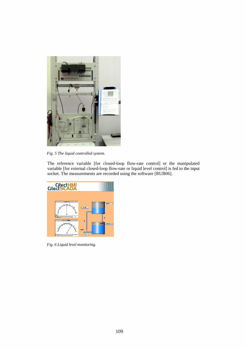
109
Fig. 5 The liquid controlled system. The reference variable [for closed-loop flow-rate control] or the manipulated variable [for external closed-loop flow-rate or liquid level control] is fed to the input socket. The measurements are recorded using the software [RUB06].
Fig. 6 Liquid level monitoring.

110
Fig. 7 Control optimization trends. The following lab works are carried out:
• Level measurement and monitoring in the S7-200 using a Sonar BERO • Automatic liquid level control with the S7-200 PI controller • Flow-rate measurement with S7-200 • Automatic flow-rate control with S7-200 PI and PID controllers.
1.3 Voltage and speed measurement The motor-generator set enables students to carry out voltage and speed experiments. The laboratory set is used to record the step response of the link, to determine the optimal control parameters or to record the timeline diagrams of the system under control. The model is used to maintain the output voltage of a generator even during load changes. The motor generator set comprises two identical 20 V DC permanent-field machines which are coupled with a flywheel. The machines have been designed for 20 V/0.47 A at which they supply n = 3000 rpm. The flywheel has 60 light/dark segments which rotate past a photo-electric barrier.

111
The load switch is provided to apply a load to machines with two-pole outputs and can be controlled either manually or automatically (fig.8).
Fig. 8 Motor-generator set. The following set of the lab works is carried out:
1. Design automatical processes with a PLC. 2. Practical experience with industrial PLCs, programming with a certified
software. 3. Automatic speed control of the motor-generator set with the PLC PID
controller. 4. Simulation of the starting and braking processes with the motor-generator
set. 5. Controller optimization according to Åström and Hägglund.
1. 4 Listing (Heel) controlled system The model has two ballast tanks filled with water. The gear pump pumps water out of one tank and into the other and back again. This changes the heel (tilt) of the ship. The heeling of the ship is influenced when the “ship’s deck“ is loaded with “containers“ in the form of small cylinder magnets. A pumping operation in the opposite direction corrects the faulty heeling (Fig. 9). This is used to investigate unstable phenomena in a non-linear system, e.g. control of a ship's position with the developed software.

112
Fig. 9 Listing (Heel ) of a controlled system. Measurement of the listing angle and conversion into the unit signal range is also possible. Inclinometer for the heeling angle measurement with the proportionality factor of the heeling angle 1 V/1.5° is used. The developed projects are:
• Programming in instruction list, function block diagram, ladder diagram. • Testing of PLC programs. • Programming with a SCADA /HMI Software.
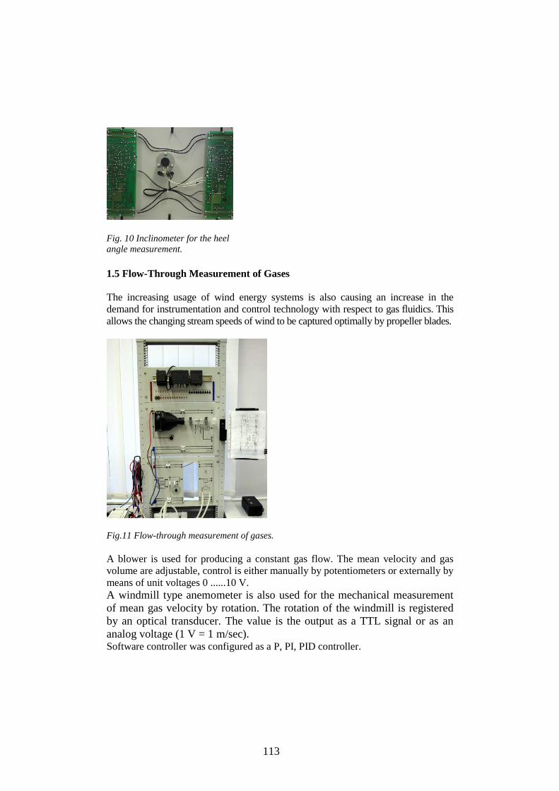
113
Fig. 10 Inclinometer for the heel angle measurement. 1.5 Flow-Through Measurement of Gases The increasing usage of wind energy systems is also causing an increase in the demand for instrumentation and control technology with respect to gas fluidics. This allows the changing stream speeds of wind to be captured optimally by propeller blades.
Fig.11 Flow-through measurement of gases. A blower is used for producing a constant gas flow. The mean velocity and gas volume are adjustable, control is either manually by potentiometers or externally by means of unit voltages 0 ......10 V. A windmill type anemometer is also used for the mechanical measurement of mean gas velocity by rotation. The rotation of the windmill is registered by an optical transducer. The value is the output as a TTL signal or as an analog voltage (1 V = 1 m/sec). Software controller was configured as a P, PI, PID controller.
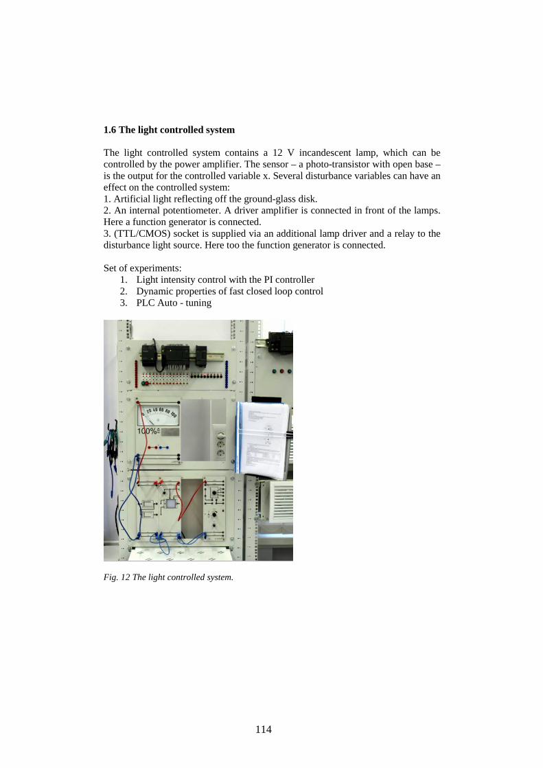
114
1.6 The light controlled system The light controlled system contains a 12 V incandescent lamp, which can be controlled by the power amplifier. The sensor – a photo-transistor with open base – is the output for the controlled variable x. Several disturbance variables can have an effect on the controlled system: 1. Artificial light reflecting off the ground-glass disk. 2. An internal potentiometer. A driver amplifier is connected in front of the lamps. Here a function generator is connected. 3. (TTL/CMOS) socket is supplied via an additional lamp driver and a relay to the disturbance light source. Here too the function generator is connected. Set of experiments:
1. Light intensity control with the PI controller 2. Dynamic properties of fast closed loop control 3. PLC Auto - tuning
Fig. 12 The light controlled system.

115
2 PLC Networks Components used for networking the automation systems are the following: S7-200 CPU 224/226 Text Display TD200 Connection cable to TD200 TC65 Terminal Connection cable PC/PPI cable 24V DC power supply LOGO! Power 1.3A Ethernet module CP243-1 IT STEP7 MicroWin32 V3.2, Toolbox V1.0 Citect SCADA V6.1 OPC server - PC Access Matriсon OPC Explorer PC with a free serial interface for running configuration software and tools 2.1 PPI interface 2.1.1 TD 200 text display Continuous real time deals with monitoring and controlling physical variables as they occur in time. TD 200 text display is connected with S7-200 and performs HMI tasks. Many keys can be positioned as required and colour symbols and text can be freely designed. The states of these output registers are then simultaneously written to the outputs (Fig. 13). Control of installation from a place occurs as from the operating buttons connected with inputs of the controller, and from the panel of operator TD200 [15] connected with serial port Port_0 of the controller by a cable with converter RS232-RS485 on the interface PPI.
. Fig. 13 PLC with the Text Display TD200.

116
The controller port 0 is reserved for the PPI connection with the TD200. Exchange speed is 9.6 kbps. TD 200 tuning is carried out in Setup Menu. The menu is configured to control the loadings mode, the current regulation parameters, and PID parameters tuning.
Fig. 14 Current parameters and alarm signals of the Text Display TD200. In cases of malfunctions occurrence, the responsible for data exchange with the TD subroutine form alarms. Alarm signals are produced by the Text Display TD200 in cases of protection operation, the sensor signals loss and malfunction of a power unit. Alarms are removed by button "ESC" after malfunction reasons are eliminated. 2.1.2 Control by means of SPPI in Citect SCADA Data exchange between the controller S7-200 and the Citect SCADA occurs under SPPI - direct connection of a point-point type. To visualize the developed project (in this case Rele toka_Prim_Citect_UINT) it is necessary to make an adjustment of the connection between the controller and SCADA.
Fig. 15 Project visualization in SCADA.

117
In cases of the sensor signal loss, the program does not give a switch-off command, but displays Alarm, and also blocks an opportunity of turn-on, while the sensor signal is not restored yet. Alarm is removed by button "Ready" after the elimination of the malfunction reason. Analog input of the module is processed 15-bit ADC. The range of a possible measured signal of a range 0-20mA will be transformed to an integer format in the range of 0-32000. In Step7 MicroWIN, the format of the input signals is Word. 2.2. Wireless signalling and switching via SMS (with S7-200 and TC65 Terminal) SIMATIC S7-200 sends wireless fault and operating messages via e-mail, or SMS message using the GSM modem TC65 Terminal. The TC65 modem can be used in nearly all GSM networks worldwide. For a wireless connection of the controlled system to a GSM network, the GSM modem TC65 Terminal is connected with the serial interface of the S7-200 CPU 224. The SIM card of define mobile service provider is placed in TC65 Terminal on sending and receiving of short messages. Fault and operating messages are transmitted to a mobile phone as SMSs. After the connection with TC65 Terminal has been established, it is possible to poll the status of variables and update the user program with STEP 7-Micro/WIN.
Fig. 16 Set-up with a GSM modem. Set-up consists of a
• S7-200 CPU 224 DC • GSM Modem TC65 Terminal. • Both components are connected via a PC/PPI cable.

118
• The 24V DC power supply LOGO! Power 1.3A. Set-up for visualization includes the S7-200 CPU 226. 2.3 Networking automation systems via Industrial Ethernet The Ethernet module CP243-1 IT was used as a physical connection between the Internet, Ethernet and S7- 200 bus. Using STEP 7, an S7-200 can be configured, programmed, and diagnosed via the Ethernet. Communication with an OPC server is also possible. The IT functions of the CP 243-1 IT form the basis for monitoring and, if necessary, also manipulating automation systems with a Web browser from a networked PC. In addition, diagnostic messages can be e-mailed from a system. Sending an e-mail was initiated by the S7-200 user program. A scheme of remote measurement and control system based on the OPC (OLE for Process Control), Ethernet and PLC consists of an S7-200 with 256 KB memory cartridge and an Ethernet CP 243- IT communications module. On the remote OPC terminal, it offeres process data to the monitor control system or offers control commands to the process devices through the OPC server's data access in VB (Visual Basic), thus the purpose of exchanging the present data is attained between the lower control level and the upper management level. Step7 Ethernet Wizard gives the controller an appropriate IP address, and IP address for access to a network (Gateway Address). Data are frequently written to the 256 KB memory cartridge (approx. every 20 seconds). Via the S7-200 Explorer integrated in STEP 7 MicroWIN, the process values can be read via Microsoft Excel and further processed. Optionally an “HMI” station can be additionally connected (Fig. 17). The following network settings have to be applied on the used network card of the PC:
• IP address: 192.168.2.141 • Subnet mask: 255.255.255.0 Data exchange with Citect SCADA occurs through the Ethernet interface with protocol TCP/IP. ОРС server PC Access is used for connection because Citect SCADA has no driver for the Ethernet connection with S7-200. PC Access is a buffer for data exchange between the controller and SCADA. Monitoring and management of the process are made from SCADA working windows.

119
Fig. 17 IP and Gateway address window. CP243-1 IT uses only one external connection with ОPC.
Fig. 18 Address window for the external device TSAP. IP controller address is assigned in Step7 MicroWin Communication.

120
Fig. 19 Windows of the controller address. 2.4 Data exchange with Modbus RTU Protocol Controller CPU226 exchanges the data with the frequency converter Commander SK, using the interface RS485 and the ModBus RTU protocol. Speed of an exchange is 19.2 kbps. The frequency converter Commander SK was connected to respond as a Modbus RTU slave. The Commander SK receives Modbus requests over the interface, interprets those requests and transfers data to or from the CPU.

121
Fig. 20 Commander SK control, data exchanging and monitoring. The Commander SK then generates a Modbus response and transmits it out over the modem interface. STEP 7 MicroWIN Instruction Libraries makes communicating to Modbus master devices easier by including pre-configured subroutines and interrupt routines that are specifically designed for Modbus communications. With the Modbus Slave Protocol Instructions, the S7-200 is configured to act as a Modbus RTU slave device and communicated to Modbus master devices.
Fig. 21 Exchange initialization block.

122
The configuration of the controller port 1 with the protocol ModBus RTU is carried out in Step7 by means of block MBUS_CTRL_P1. It defines the data exchange speed, slave-device parity and the waiting time. Emergency switch-off of frequency drive variables: Bit V734.6 is FC_switch_OFF bit. EM243_1_IT_Error bit V734.7 Ethernet module error AIW2_No_signal bit V733.0 No signal of Analog module EM235 input 2; ModBus_Error bit V733.1 ModBus protocol error; AIW0_No_signal bit V733.2 No signal of Analog module EM235 input 1; EM235_Error bit V733.3 Analog module EM235 error;
Fig. 22 Current control monitoring. 2.5 Data reading from the S7-200 CPU via the OPC client Excel with the OPC server PC Access and archiving in the Access database With the S7-200 Explorer, the data records can be opened and displayed using Microsoft Excel. The operating systems Windows 2000 and Windows XP support "Visual Basic for Applications" (VBA). Using the VBA program code has been generated in Microsoft Excel for archiving values of the S7-200 CPU in an MS Access database. This example shows how to archive values from the S7-200 in an Access database using an Excel client.

123
Fig. 23 Graphical display of PLC variables via Excel as OPC client with PC Access as OPC server. S7-200 PC Access Excel client displays the variables (Current and Temp) of the S7-200 controller. Access to the variable area is always via the DB1 of the S7-200 CPU.

124
APPENDIX 3
ELULOOKIRJELDUS 1. Isikuandmed
Ees- ja perekonnanimi Olga Ruban
Sünniaeg ja –koht 01.01.1950 Saraatovi oblast, Venemaa Kodakondsus Eesti 2. Kontaktandmed Aadress Pärna 40-27, 30326 Kohtla-Järve Telefon 55626826 E-posti aadress [email protected] 3. Hariduskäik
4. Keelteoskus (alg-, kesk- või kõrgtase)
Keel Tase
Eesti kesktase
Vene kõrgtase
Inglise kesktase
5. Täiendusõpe
Õppimise aeg Täiendusõppe läbiviija nimetus 21 – 29.03. 2003. a Elektroonsed regulaatorid, kui kaasaegsed
tööstuse automatiseerimise vahendid, 40 t 21 – 22. 12. 2005 a “SolidWorks baaskoolitus”
2 – 14. 12. 2007. a. Programmeeritavad kontrollerid Siemens S7
(PRO1,PRO2), 80 t.
Õppeasutus (nimetus lõpetamise ajal)
Lõpetamise aeg Haridus (eriala/kraad)
Tallinna Tehnikaülikool 2002 Kutseõpetaja
Saraatovi Riiklik Ülikool 1972 Füüsik, Pooljuhid ja dielektrikud
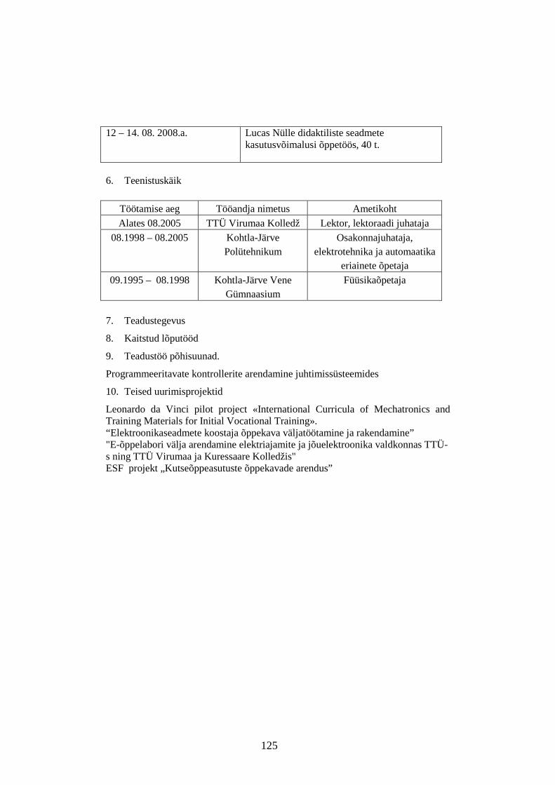
125
12 – 14. 08. 2008.a. Lucas Nülle didaktiliste seadmete kasutusvõimalusi õppetöös, 40 t.
6. Teenistuskäik
Töötamise aeg Tööandja nimetus Ametikoht
Alates 08.2005 TTÜ Virumaa Kolledž Lektor, lektoraadi juhataja
08.1998 – 08.2005 Kohtla-Järve Polütehnikum
Osakonnajuhataja, elektrotehnika ja automaatika
eriainete õpetaja
09.1995 – 08.1998 Kohtla-Järve Vene Gümnaasium
Füüsikaõpetaja
7. Teadustegevus
8. Kaitstud lõputööd
9. Teadustöö põhisuunad.
Programmeeritavate kontrollerite arendamine juhtimissüsteemides
10. Teised uurimisprojektid
Leonardo da Vinci pilot project «International Curricula of Mechatronics and Training Materials for Initial Vocational Training». “Elektroonikaseadmete koostaja õppekava väljatöötamine ja rakendamine” "E-õppelabori välja arendamine elektriajamite ja jõuelektroonika valdkonnas TTÜ-s ning TTÜ Virumaa ja Kuressaare Kolledžis" ESF projekt „Kutseõppeasutuste õppekavade arendus”

126
CURRICULUM VITAE
1. Personal data
Name Olga Ruban
Date and place of birth 01.01.1950 Saratov, Russia 2. Contact information
Address Pärna 40-27, 30326, Kohtla-Järve Phone 55626826 E-mail [email protected] 3. Education
4. Language competence/skills (fluent; average, basic skills)
Language Level
Estonian Average
English Average
Russian Fluent
5. Special Courses
Period Educational or other organization
21 – 29.03. 2003 Controllers as modern item of control systems 40 h“
21 – 22.12. 2005 “Solid Works” based course
2 – 14 .12. 2007 PRO-1, PRO-2 Siemens S7 80 h.
12 – 14. 08. 2008 Lucas Nülle equipment opportunities 40 h.
Educational institution Graduation year Education (field of study/degree)
Saratov State University,
1972 Electronic Engineer
Tallinn University of Technology
2002
Special subjects teacher

127
6. Professional Employment
Period Organisation Position since 2005
Virumaa College of Tallinn University of Technology
Lecturer on technical subjects
1998 – 2005
Kohtla–Järve Polytechnic Lecturer
1996 – 1998 Kohtla–Järve Russian Secondary School
Teacher
7. Scientific work
Theoretical and applied problems of process control with a PLC. 8. Main areas of scientific work/Current research topics
Some aspects of the use of programmable logic controllers in closed- loop control systems. 9. Other research projects
Project “Elektroonikaseadmete koostaja õppekava väljatöötamine ja rakendamine” Leonardo da Vinci pilot project ”International Curricula of Mechatronics and Training Materials for Initial Vocational Training” “Elektroonikaseadmete koostaja õppekava väljatöötamine ja rakendamine” "E-õppelabori välja arendamine elektriajamite ja jõuelektroonika valdkonnas TTÜs ning TTÜ Virumaa ja Kuressaare Kolledžis" ESF projekt „Kutseõppeasutuste õppekavade arendus”


![[8] Control de Bombas PLC -Main](https://img.pdfslide.us/doc/110x75/563db8fe550346aa9a98f225/8-control-de-bombas-plc-main.jpg)


![Control Adores PLC COPIP[1]](https://img.pdfslide.us/doc/110x75/577d25041a28ab4e1e9dea35/control-adores-plc-copip1.jpg)