Embed Size (px)
Citation preview

International Journal of Science and Research (IJSR) ISSN (Online): 2319-7064
Index Copernicus Value (2013): 6.14 | Impact Factor (2013): 4.438
Volume 4 Issue 4, April 2015
www.ijsr.net Licensed Under Creative Commons Attribution CC BY
Analysis and Design of Skew Bridges
Nikhil V. Deshmukh1, Dr. U. P. Waghe
2
1P.G. Student (M-Tech - Structures), Y.C.C.E., Nagpur- 441110, Maharashtra, India
2Principal & Professor, Yeshwantrao Chavan College of Engineering, Nagpur- 441110, Maharashtra, India
Abstract: Bridges are very special type of structures. They are characterized by their simplicity in geometry and loading conditions.
The reinforced concrete bridges usually carried uniformly distributed dead load, vehicular live load to its surface and transfers same to
the support by flexure, shear and torsion. Newly designed bridges are often skew. This is due to space constraints in congested urban
areas. It can be also needed due to geographical constraints such as mountainous terrains. However force flow in skew bridges is much
more complicated than straight bridges. Therefore careful investigation and numerical analysis needs to be performed, in which a skew
bridges can be modeled in several ways. Skewed slab bridges were modeled using finite-element methods using CsiBridge computer
software to study their behavior under uniform and moving loads with to determine the most appropriate force response for design.
Keywords: Skew Angle, Finite Element Method, IRC Class A Loading
1. Introduction
The majority of bridge decks that are constructed now days
are often some skewed or curved. Tight geometry is often
placed on highway structures due to right of way restrictions
in congested urban areas. If a road alignment crosses a river
or any other obstruction at an inclination different from 90°,
a skew crossing may be necessary. Skewed bridges are one
of the most economical and satisfying construction in such
conditions. In addition skew bridges are common at highway
interchange, river crossing and other extreme grade changes
where skew geometry is necessary due to space limitations.
In fair meaning, the plan of bridge may appear like
parallelogram in plan view. This condition occurs when
bridge alignment is not exact perpendicular or making some
angle to crossing. The term angle of skew or skew angle is
generally applied to the difference between alignments of an
intermediate or end support and a line square to the
longitudinal axis of the bridge above. Thus, on straight
bridge, the skew angle at all supports would normally be the
same and the term skew angle can be applied to the bridge as
a whole. The simple form of bridge is right deck but demand
of skew bridge is increasing due to various factors.
2. Literature Review
[1]Vikash Khatri, Anshuman Khar, P. K. Singh, P. R. Maitiin
their research work conducted grillage analysis method for
analysis of bridges. A total of nine different grid sizes (4
divisions to 12 divisions) are made using grillage analogy
and have been studied on skew angles 30°, 45° and 60° to
determine the most effective grid size. In their study is
observed that finite element method (FEM) and Grillage
method results are not similar for every grid size. They can
be different for each grid size depending on various
parameters. It is also observed from the analysis that mostly
seven divisions on gridding is appropriate i.e., ratio of
transverse grid lines to longitudinal grid lines is 1.8-2.0.
Also variation of grid sizes analysis results predicts that,
variation in reaction value is same in FEM and Grillage
method but variation of bending and torsion moment in
FEM is lower than grillage results. So, FEM may be
preferred for analysis of skew bridges.
[2]Arindham Dhar, Mithil Mujumdaar, Mandakini
Chowdhary, Somnath Karmakar presented the comparison
between behavioral aspects of a skew bridge by creating and
analyzing straight counterparts using a 3D Bridge model in
Finite Element Analysis software – ABAQUS in their
research work. The results of the bridge model in ABAQUS
show that with the increase in the skew angle, the support
shear and mid-span moments of obtuse longitudinal girders
increases while these parameters decrease with the
corresponding acute angle in longitudinal girders. Most
importantly, the increase un torsional moment is observed
with rapid increase in obtuse skew angle in longitudinal
girder. Although the changes are insignificant for inclusion
in the design up to 20º skew, but at higher skew angles the
increase is considerable (25% increase for 45º skew). These
changes must be taken into account for correctly designing
an obtuse girder. They also pointed out that with the
increasing skew angle, torsional moments rise rapidly in
obtuse angled girders.
[3]
M. Ameerutheen, Sri. Aravindan in performed their
research study on the two lanes solid slab and on beam and
slab arrangement (composite) on various skew angles.
1tonne/sq m of imposed load is given on each model and
comparison of the results is observed to study the
characteristics of skew deck and also investigational study
on the skew effect if the bridge is subjected to IRC loading
is completed. The analysis is done using the software
STAAD-PRO to study the effect of stresses in Solid slab &
Composite Bridge Deck slab. The effect of Skew angle in
Composite Bridge is observed for same modesl using
STAAD-PRO. The critical section in skew angle where
behavior is dominant is also found out by this analysis
which can be effectively used while designing skew bridge.
[4]
Mehrdad Bisadi in his research carried out finite element
(FE) analysis on an existing railway bridge. For this
purpose, the railway bridge is customized and analyzed by
using finite element software, LUSAS. Analysis for Eigen
value and moving load is carried out to obtain the natural
frequencies and the displacement of the simulated model
under the axial load of train passage. Different values of
damping ratios and Young’s modulus are used in these
Paper ID: SUB153017 399
International Journal of Science and Research (IJSR) ISSN (Online): 2319-7064
Index Copernicus Value (2013): 6.14 | Impact Factor (2013): 4.438
Volume 4 Issue 4, April 2015
www.ijsr.net Licensed Under Creative Commons Attribution CC BY
analyses to observe the effects of these values which are
presented in this study. Meanwhile, different values of
damping ratios and Young’s modulus were used and the
effects of them have shown in such an analytical study. It
has shown that these two parameters, damping ratio and
Young’s modulus, played a key role in the dynamic
behaviour of the bridge.
3. Modeling and Analysis
The FEM consists of solving mathematical model which is
obtained by idealizing structure as an assembly of various
discrete two or three dimensional element which are
connected to each other at their nodal points, provided an
appropriate number of degrees of freedom is used at each
time. IRC Load Combinations of bridges has been
implemented within CsiBridge. . In bridge deck analysis the
few dominant places where maximum bending moment,
shear force and torsional force are loading places at centre
and near support of span. Considerable power and flexibility
is provided for determining the maximum and minimum
displacements, forces, and stresses from multiple-lane loads
on complex structures, such as highway interchanges.
For each model, the model configuration is kept same, only
skew angle is changed from 15° to 45°. Span of 6m, 8, 10m
and 12m bridge is considered for each IRC Class A Loading.
The main aim in this study is to observe and conclude
bending moment, torsional moment and shear force with
respect to change in skew angle.
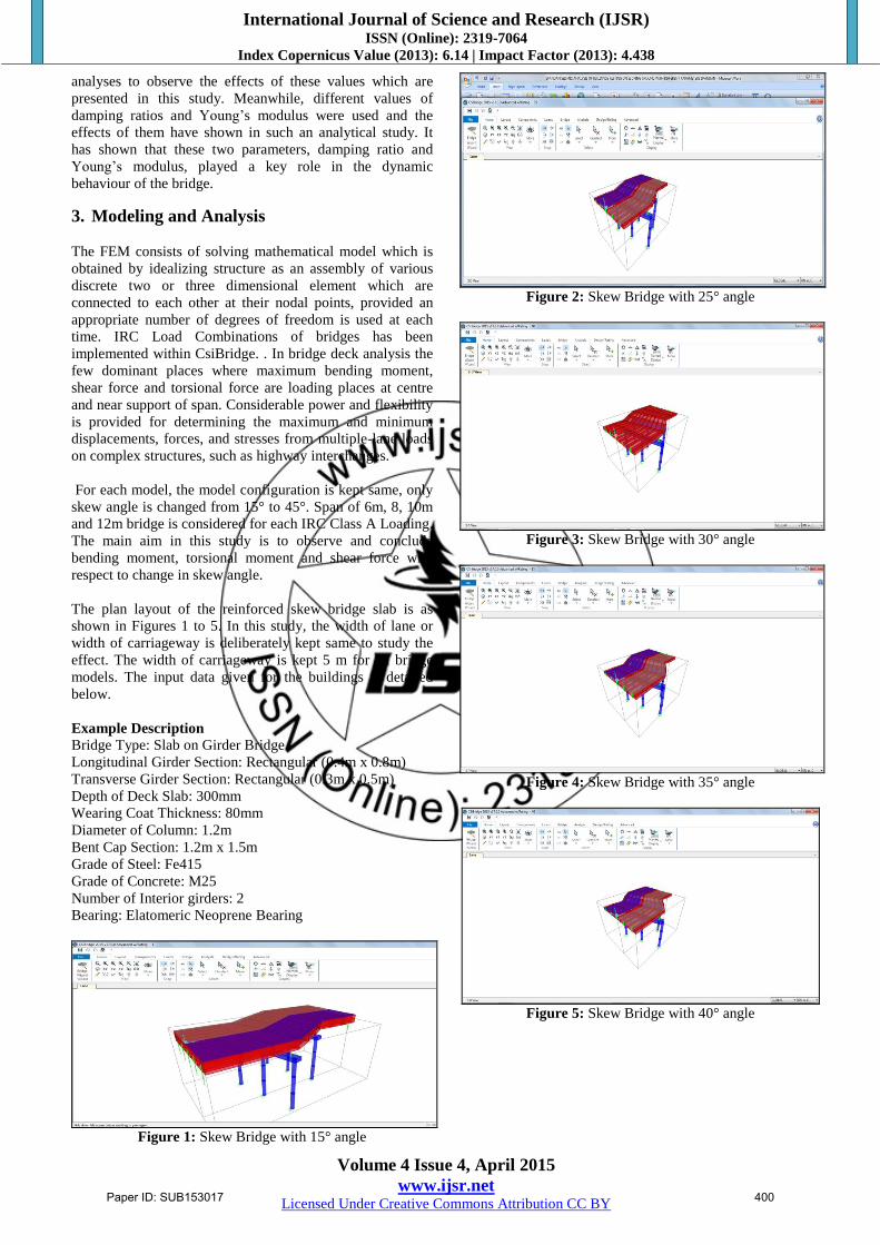
The plan layout of the reinforced skew bridge slab is as
shown in Figures 1 to 5. In this study, the width of lane or
width of carriageway is deliberately kept same to study the
effect. The width of carriageway is kept 5 m for all bridge
models. The input data given for the buildings is detailed
below.
Example Description
Bridge Type: Slab on Girder Bridge
Longitudinal Girder Section: Rectangular (0.4m x 0.8m)
Transverse Girder Section: Rectangular (0.3m x 0.5m)
Depth of Deck Slab: 300mm
Wearing Coat Thickness: 80mm
Diameter of Column: 1.2m
Bent Cap Section: 1.2m x 1.5m
Grade of Steel: Fe415
Grade of Concrete: M25
Number of Interior girders: 2
Bearing: Elatomeric Neoprene Bearing
Figure 1: Skew Bridge with 15° angle
Figure 2: Skew Bridge with 25° angle
Figure 3: Skew Bridge with 30° angle
Figure 4: Skew Bridge with 35° angle
Figure 5: Skew Bridge with 40° angle
Paper ID: SUB153017 400

International Journal of Science and Research (IJSR) ISSN (Online): 2319-7064
Index Copernicus Value (2013): 6.14 | Impact Factor (2013): 4.438
Volume 4 Issue 4, April 2015
www.ijsr.net Licensed Under Creative Commons Attribution CC BY
Figure 6: Skew Bridge with 30° angle
4. Result and Discussion
1) Shear Force
The maximum shear forces at each skew bridge with respect
to their spans are presented in Graphical format. For better
comparability the shear force of each graph contain the table
of observed reading.
SHEAR FORCE (kN)
Skew
Angle
Span
4 6 8 10 12
15° 257.43 346.25 413.94 465.82 557.92
25° 433.09 353.14 415.94 502.72 560.06
30° 443.6 375.18 416.98 503.74 561.75
35° 445.83 350.26 418.02 504.93 563.67
40° 448.37 372.45 419.18 506.83 565.01
45° 440.92 377.05 416.66 509.24 566.58
2) Bending Moment
The maximum bending moment is observed during
increment in skew angle. Also increase in span length will
cause effect of bending moment on bridges.
BENDING MOMENT (kN-m)
Skew
Angle
Span
4 6 8 10 12
15° 535.48 382.73 461.77 709.91 1041.75
25° 522.19 387.36 477.33 721.4 1060.27
30° 514.04 397.25 480.24 734.18 1073.58
35° 509.5 407.25 495.52 734.98 1093.48
40° 541.56 420.02 514.33 738.28 1119.07
45° 494.11 365.02 545.39 736.87 1154.12
3) Torsional Moment
Torsional moment occurs due to effect of cantilever load
transfer in skew slab. The increase of torsional moment is
observed with increase in span length and skew angle.
Torsional Moment (kN-m)
Skew
Angle
Span
4 6 8 10 12
15° 735.57 622.61 770.46 898.93 1090.39
25° 748.14 642.24 767.17 894.74 1092.82
30° 761.87 687.44 768.57 948.49 1094.21
35° 755.61 699.19 771.41 947.14 1095.78
40° 750.25 706.13 777.82 977.45 1097.47
45° 748.73 719.08 785.19 1010.11 1100.38
5. Conclusions
Based on analysis of different configurations of bridges, the
following conclusions can be drawn:
1) For Class A Loading the increase in shear force for low
skew angle (<15°) the shear force increases linearly. The
pattern of increase of shear force with respect to span is
straight in nature.
2) There is about 20% increase in shear force when span
increases from 4m to 6m. As the skew angle is increase,
shear force is decreased about 30% when span change to
6m from 4m from thereon, hear force for each span
increase.
3) The bending moment increases with increase of skew
angle and spans of bridges. For each span and skew
Paper ID: SUB153017 401

International Journal of Science and Research (IJSR) ISSN (Online): 2319-7064
Index Copernicus Value (2013): 6.14 | Impact Factor (2013): 4.438
Volume 4 Issue 4, April 2015
www.ijsr.net Licensed Under Creative Commons Attribution CC BY
angle, the change of about 20% is observed in bending
moment nature.
4) In case of torsional moment, the pattern of increment in
torsional moment is similar to pattern of bending
moment. There is about 10% of linear variation increase
in torsional moment comparing to bending moment can
be noticed broadly.
While adopting design under Class A Loading, designer
must give proper attention to torsional moment as much as
bending moment. High torsional moments are observed for
skew angle more than 30°. There might be requirement of
torsional reinforcement to counteract these torsional moments in bridges. There is sharp decrease in shear force
response for low span bridges even with high skew angle.
The bending moment increase with increase in skew angle
and span length.
References
[1] Vikash Khatri, P. R. Maiti, P. K. Singh & Ansuman
Kar, “Analysis Of Skew Bridges Using Computational
Methods” International Journal Of Computational
Engineering Research. May-June 2012, Vol. 2, Issue
No. 3, 628-636
[2] Arindham Dhar, Mithil Mujumdaar, Mandakini
Chowdhary, Somnath Karmakar, “Effect Of Skew
Angle On Longitudinal Girder (Support Shear, Moment,
Torsion) And Deck Slab Of An Irc Skew Bridge.” The
Indian Concrete Journal, December 2013, 47-52
[3] M. Ameerutheen, Sri. Aravindan, “Study of Stresses on
Composite Girder Bridge Over Square and Skew Span”
International Journal of Civil Engineering and
Technology (Ijciet), February 2014, Volume 5, Issue 2,
88-96
[4] Mehrdad Bisadi, “Moving Load Analysis on Skewed
Railway Bridge” Journal of Asian Scientific Research,
2013, 3(2), 198-203
[5] Indian Road Congress, New Delhi IRC 6-2000,
“Standard Specification and Code of Practice for Road
Bridges”, Section II “Loads and Stresses”, Indian Road
Congress, New Delhi.
[6] M. S. Qaqish, “Effect of Skew Angle on Distribution of
Bending Moments in Bridge Slabs”, Journal of Applied
Science 6 (2): 366-372, 2006
[7] Essentials of Bridge Engineering by D. Johnson Victor,
Oxford & IBH Publishing Co. Pvt. Ltd, New Delhi,
Sixth Edition, PP 122-124
Paper ID: SUB153017 402