Embed Size (px)
Citation preview
1
Prof. Dr. Qaisar Ali Reinforced Concrete Design – II
Department of Civil Engineering, University of Engineering and Technology Peshawar
Lecture-02
Analysis and Design of One-way Slab System
(Part-I)
By: Prof Dr. Qaisar Ali
Civil Engineering Department
UET Peshawarwww.drqaisarali.com
1
Prof. Dr. Qaisar Ali Reinforced Concrete Design – II
Department of Civil Engineering, University of Engineering and Technology Peshawar
Topics Addressed
Concrete Floor Systems
Analysis and Design of Slabs
Basic Design Steps
Example: Design of 90′ x 60′ Hall
References
2
2
Prof. Dr. Qaisar Ali Reinforced Concrete Design – II
Department of Civil Engineering, University of Engineering and Technology Peshawar
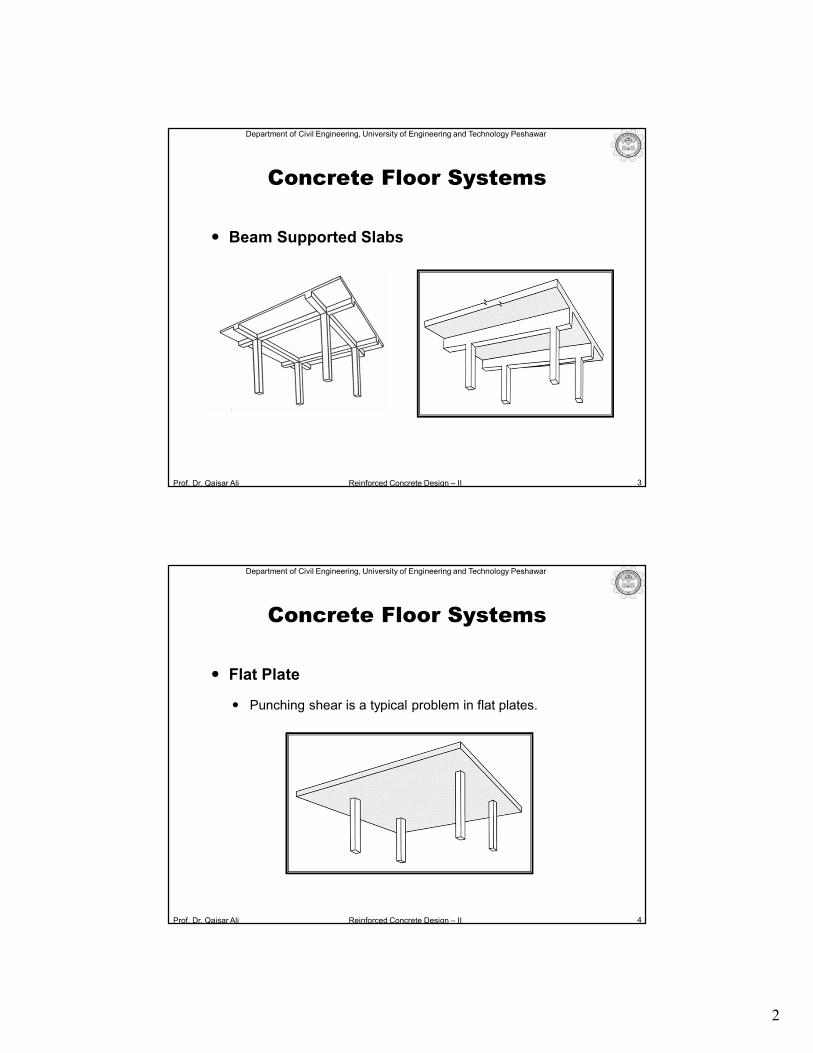
Concrete Floor Systems
Beam Supported Slabs
3
Prof. Dr. Qaisar Ali Reinforced Concrete Design – II
Department of Civil Engineering, University of Engineering and Technology Peshawar
Flat Plate
Punching shear is a typical problem in flat plates.
4
Concrete Floor Systems
3
Prof. Dr. Qaisar Ali Reinforced Concrete Design – II
Department of Civil Engineering, University of Engineering and Technology Peshawar
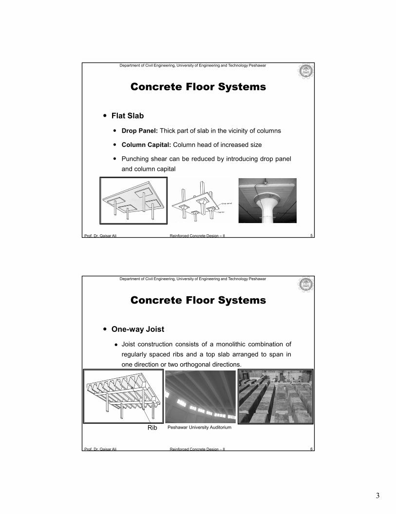
Flat Slab
Drop Panel: Thick part of slab in the vicinity of columns
Column Capital: Column head of increased size
Punching shear can be reduced by introducing drop panel
and column capital
5
Concrete Floor Systems
Prof. Dr. Qaisar Ali Reinforced Concrete Design – II
Department of Civil Engineering, University of Engineering and Technology Peshawar
6
Concrete Floor Systems
One-way Joist
Joist construction consists of a monolithic combination of
regularly spaced ribs and a top slab arranged to span in
one direction or two orthogonal directions.
Rib Peshawar University Auditorium
4
Prof. Dr. Qaisar Ali Reinforced Concrete Design – II
Department of Civil Engineering, University of Engineering and Technology Peshawar
7
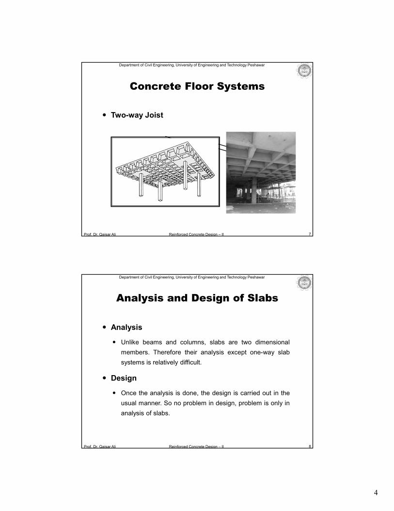
Concrete Floor Systems
Two-way Joist
Prof. Dr. Qaisar Ali Reinforced Concrete Design – II
Department of Civil Engineering, University of Engineering and Technology Peshawar
Analysis and Design of Slabs
8
Analysis
Unlike beams and columns, slabs are two dimensional
members. Therefore their analysis except one-way slab
systems is relatively difficult.
Design
Once the analysis is done, the design is carried out in the
usual manner. So no problem in design, problem is only in
analysis of slabs.
5
Prof. Dr. Qaisar Ali Reinforced Concrete Design – II
Department of Civil Engineering, University of Engineering and Technology Peshawar
Analysis and Design of Slabs
9
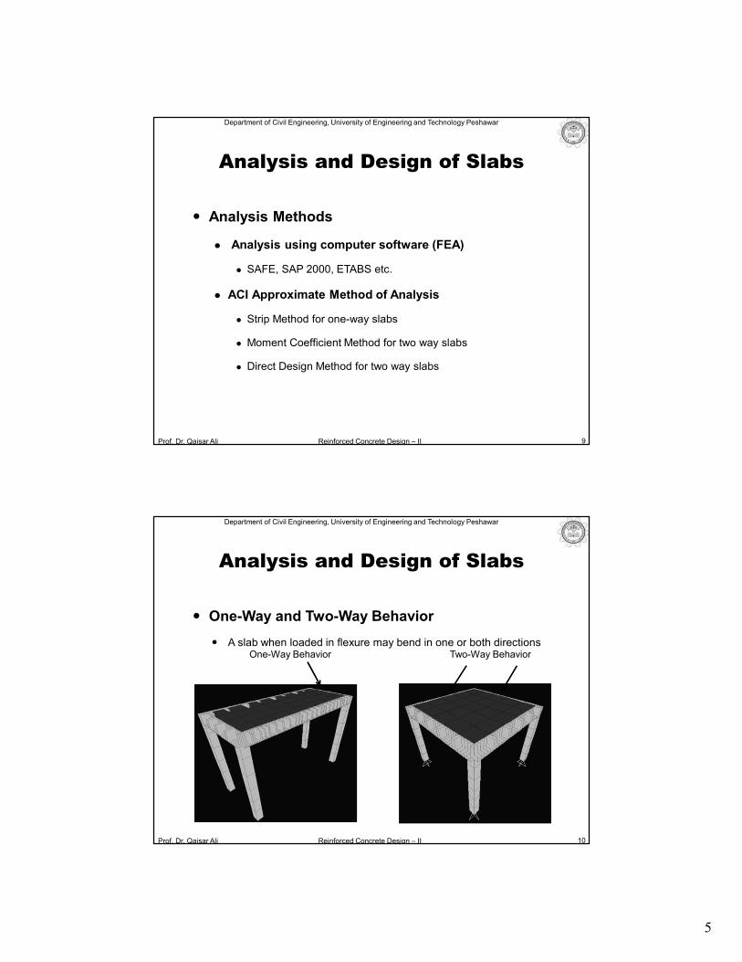
Analysis Methods
Analysis using computer software (FEA)
SAFE, SAP 2000, ETABS etc.
ACI Approximate Method of Analysis
Strip Method for one-way slabs
Moment Coefficient Method for two way slabs
Direct Design Method for two way slabs
Prof. Dr. Qaisar Ali Reinforced Concrete Design – II
Department of Civil Engineering, University of Engineering and Technology Peshawar
10
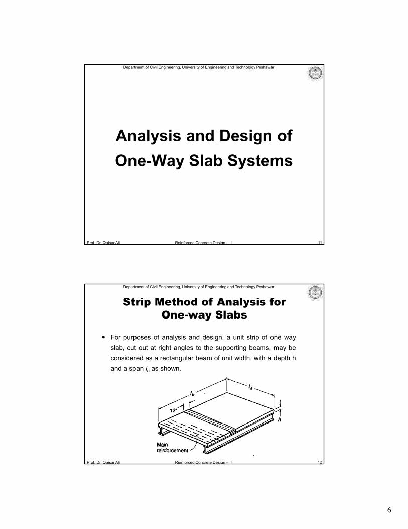
Analysis and Design of Slabs
One-Way Behavior Two-Way Behavior
One-Way and Two-Way Behavior
A slab when loaded in flexure may bend in one or both directions
6
Prof. Dr. Qaisar Ali Reinforced Concrete Design – II
Department of Civil Engineering, University of Engineering and Technology Peshawar
Analysis and Design of
One-Way Slab Systems
11
Prof. Dr. Qaisar Ali Reinforced Concrete Design – II
Department of Civil Engineering, University of Engineering and Technology Peshawar
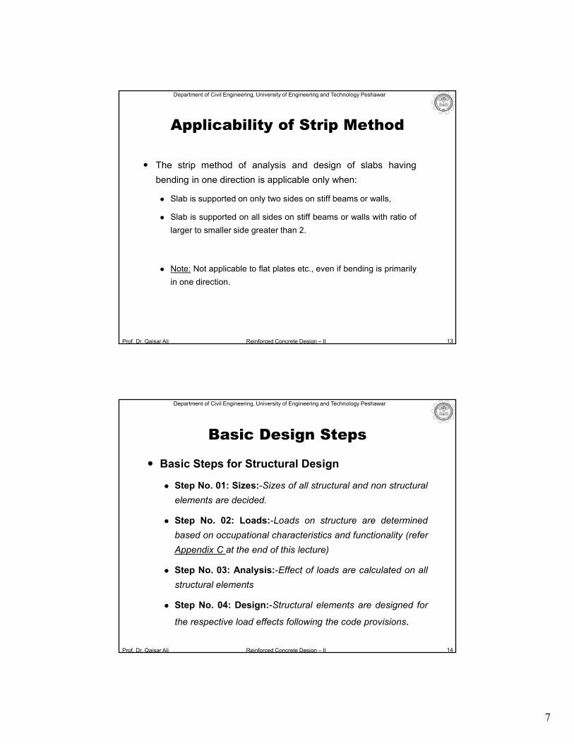
For purposes of analysis and design, a unit strip of one way
slab, cut out at right angles to the supporting beams, may be
considered as a rectangular beam of unit width, with a depth h
and a span la as shown.
12
Strip Method of Analysis for One-way Slabs
7
Prof. Dr. Qaisar Ali Reinforced Concrete Design – II
Department of Civil Engineering, University of Engineering and Technology Peshawar
The strip method of analysis and design of slabs having
bending in one direction is applicable only when:
Slab is supported on only two sides on stiff beams or walls,
Slab is supported on all sides on stiff beams or walls with ratio of
larger to smaller side greater than 2.
Note: Not applicable to flat plates etc., even if bending is primarily
in one direction.
13
Applicability of Strip Method
Prof. Dr. Qaisar Ali Reinforced Concrete Design – II
Department of Civil Engineering, University of Engineering and Technology Peshawar
Basic Design Steps
Basic Steps for Structural Design
Step No. 01: Sizes:-Sizes of all structural and non structural
elements are decided.
Step No. 02: Loads:-Loads on structure are determined
based on occupational characteristics and functionality (refer
Appendix C at the end of this lecture)
Step No. 03: Analysis:-Effect of loads are calculated on all
structural elements
Step No. 04: Design:-Structural elements are designed for
the respective load effects following the code provisions.
14
8
Prof. Dr. Qaisar Ali Reinforced Concrete Design – II
Department of Civil Engineering, University of Engineering and Technology Peshawar
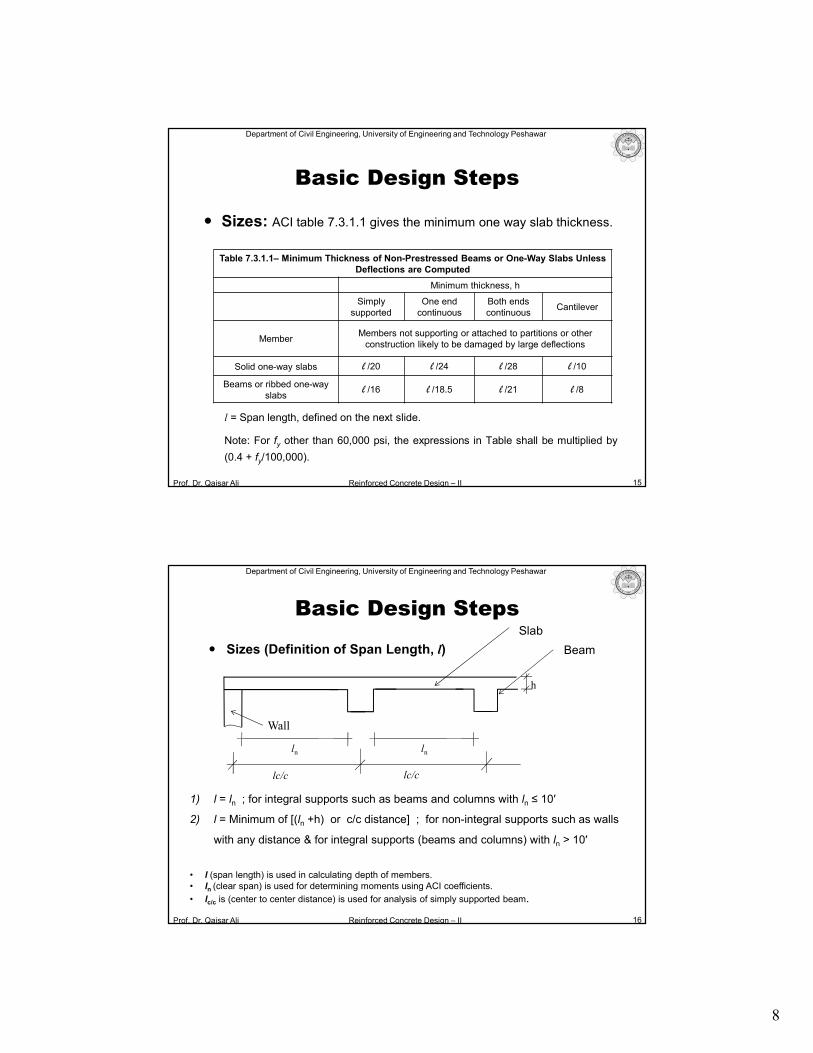
Sizes: ACI table 7.3.1.1 gives the minimum one way slab thickness.
l = Span length, defined on the next slide.
Note: For fy other than 60,000 psi, the expressions in Table shall be multiplied by
(0.4 + fy/100,000).
15
Basic Design Steps
Table 7.3.1.1– Minimum Thickness of Non-Prestressed Beams or One-Way Slabs Unless Deflections are Computed
Minimum thickness, h
Simplysupported
One end continuous
Both endscontinuous
Cantilever
MemberMembers not supporting or attached to partitions or other
construction likely to be damaged by large deflections
Solid one-way slabs l /20 l /24 l /28 l /10
Beams or ribbed one-way slabs
l /16 l /18.5 l /21 l /8
Prof. Dr. Qaisar Ali Reinforced Concrete Design – II
Department of Civil Engineering, University of Engineering and Technology Peshawar
Sizes (Definition of Span Length, l)
16
Slab
1) l = ln ; for integral supports such as beams and columns with ln ≤ 10′
2) l = Minimum of [(ln +h) or c/c distance] ; for non-integral supports such as walls
with any distance & for integral supports (beams and columns) with ln > 10′
• l (span length) is used in calculating depth of members.• ln (clear span) is used for determining moments using ACI coefficients.
• lc/c is (center to center distance) is used for analysis of simply supported beam.
Wall
lc/c lc/c
ln ln
h
Basic Design Steps
Beam
9
Prof. Dr. Qaisar Ali Reinforced Concrete Design – II
Department of Civil Engineering, University of Engineering and Technology Peshawar
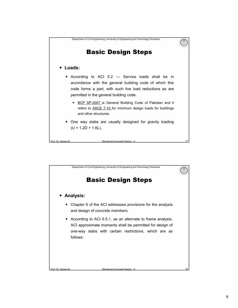
Loads:
According to ACI 5.2 — Service loads shall be in
accordance with the general building code of which this
code forms a part, with such live load reductions as are
permitted in the general building code.
BCP SP-2007 is General Building Code of Pakistan and it
refers to ASCE 7-10 for minimum design loads for buildings
and other structures.
One way slabs are usually designed for gravity loading
(U = 1.2D + 1.6L).
17
Basic Design Steps
Prof. Dr. Qaisar Ali Reinforced Concrete Design – II
Department of Civil Engineering, University of Engineering and Technology Peshawar
Analysis:
Chapter 6 of the ACI addresses provisions for the analysis
and design of concrete members.
According to ACI 6.5.1, as an alternate to frame analysis,
ACI approximate moments shall be permitted for design of
one-way slabs with certain restrictions, which are as
follows:
18
Basic Design Steps
10
Prof. Dr. Qaisar Ali Reinforced Concrete Design – II
Department of Civil Engineering, University of Engineering and Technology Peshawar
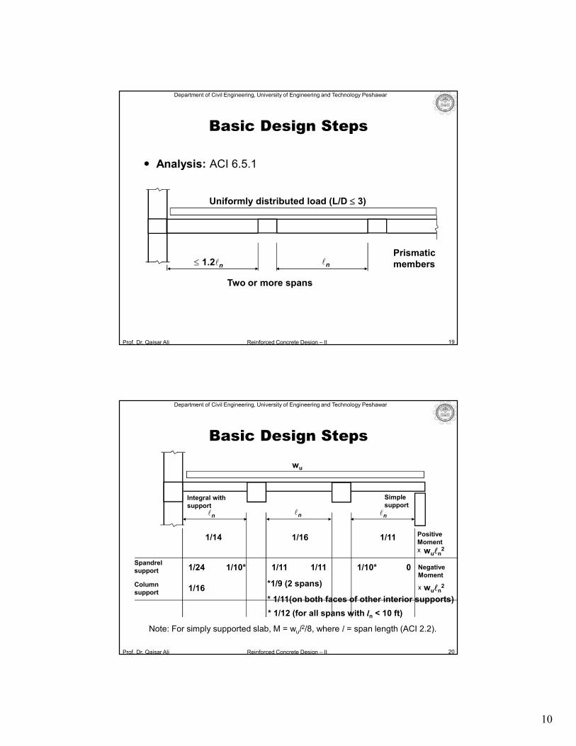
Analysis: ACI 6.5.1
19
Uniformly distributed load (L/D 3)
1.2ln ln
Two or more spans
Prismaticmembers
Basic Design Steps
Prof. Dr. Qaisar Ali Reinforced Concrete Design – II
Department of Civil Engineering, University of Engineering and Technology Peshawar
20
lnln ln
Simplesupport
Integral withsupport
wu
Spandrelsupport
NegativeMoment
x wuln2
1/24 1/10* 1/11 1/11 1/10* 0
*1/9 (2 spans)
* 1/11(on both faces of other interior supports)
Columnsupport
1/16
PositiveMomentx
1/14 1/16 1/11
wuln2
Note: For simply supported slab, M = wul2/8, where l = span length (ACI 2.2).
Basic Design Steps
* 1/12 (for all spans with ln < 10 ft)
11
Prof. Dr. Qaisar Ali Reinforced Concrete Design – II
Department of Civil Engineering, University of Engineering and Technology Peshawar
Design:
Capacity Demand
Capacity or Design Strength = Strength Reduction Factor
(f) Nominal Strength
Demand = Load Factor Service Load Effects
Bar spacing (in inches) = Ab/As × 12
(Ab = area of bar in in2, As = Design steel in in2/ft)
21
Basic Design Steps
Prof. Dr. Qaisar Ali Reinforced Concrete Design – II
Department of Civil Engineering, University of Engineering and Technology Peshawar
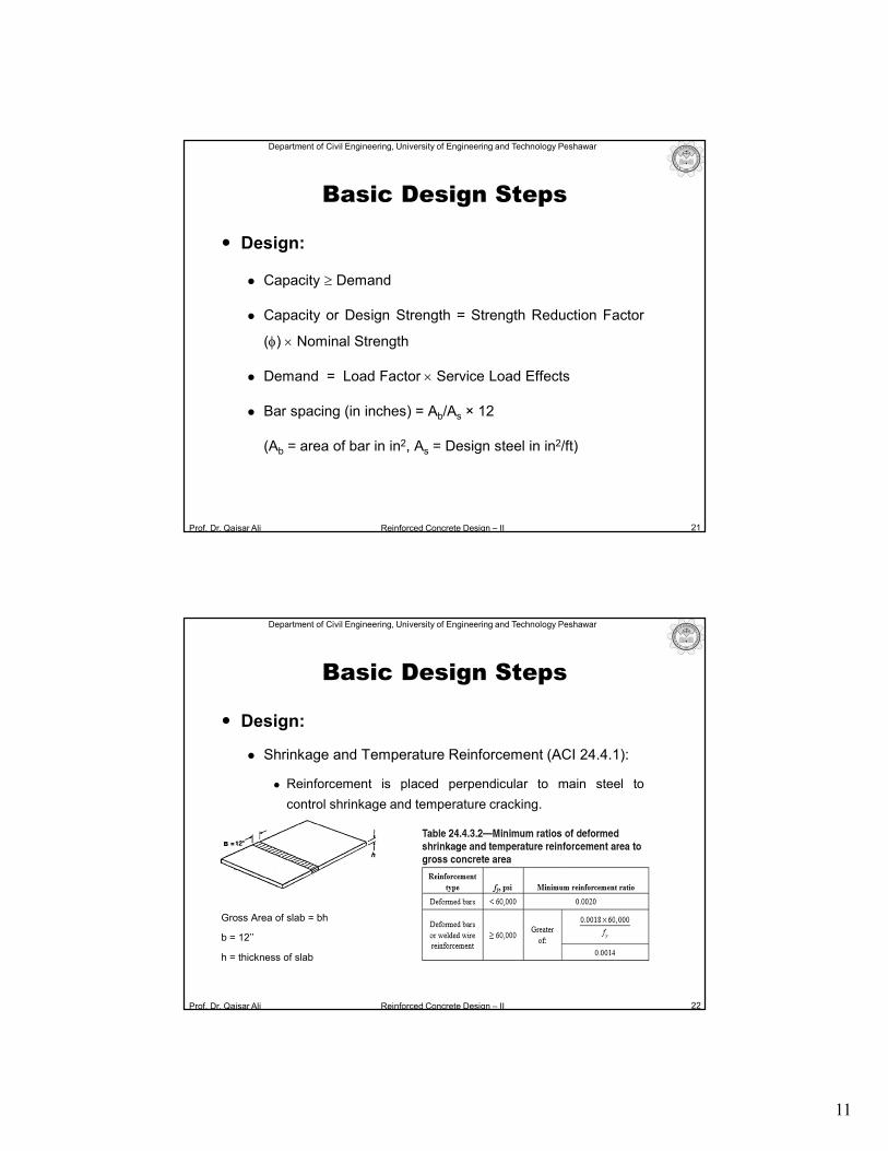
Design:
Shrinkage and Temperature Reinforcement (ACI 24.4.1):
Reinforcement is placed perpendicular to main steel to
control shrinkage and temperature cracking.
Gross Area of slab = bh
b = 12’’
h = thickness of slab
22
Basic Design Steps
12
Prof. Dr. Qaisar Ali Reinforced Concrete Design – II
Department of Civil Engineering, University of Engineering and Technology Peshawar
Design:
Maximum Spacing Requirement:
Main Reinforcement
Least of 3h or 18” (ACI 7.7.2.3)
Shrinkage Reinforcement
Least of 5h or 18” (ACI 7.7.6.2.1)
Minimum reinforcement Requirement for main reinforcement
Same as shrinkage reinforcement requirement (ACI 24.4.1)
23
Basic Design Steps
Prof. Dr. Qaisar Ali Reinforced Concrete Design – II
Department of Civil Engineering, University of Engineering and Technology Peshawar
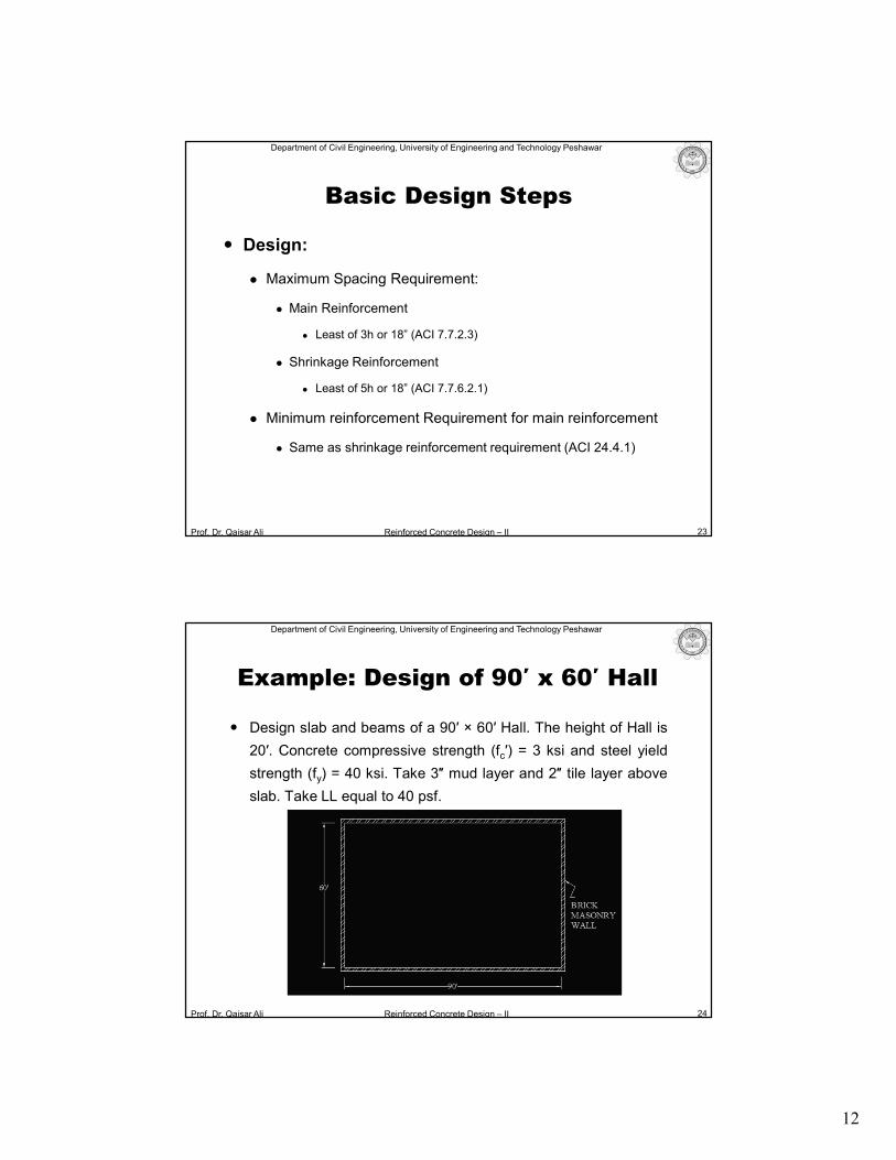
Example: Design of 90′ x 60′ Hall
Design slab and beams of a 90′ × 60′ Hall. The height of Hall is
20′. Concrete compressive strength (fc′) = 3 ksi and steel yield
strength (fy) = 40 ksi. Take 3″ mud layer and 2″ tile layer above
slab. Take LL equal to 40 psf.
24
13
Prof. Dr. Qaisar Ali Reinforced Concrete Design – II
Department of Civil Engineering, University of Engineering and Technology Peshawar
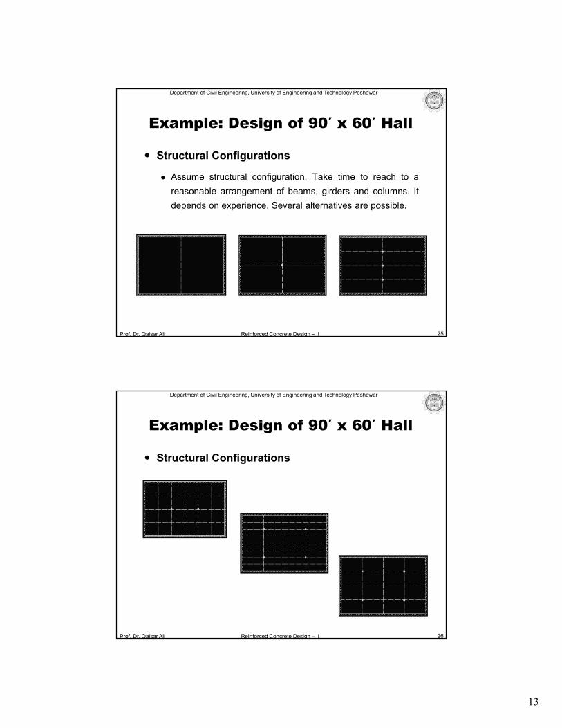
Structural Configurations
Assume structural configuration. Take time to reach to a
reasonable arrangement of beams, girders and columns. It
depends on experience. Several alternatives are possible.
25
Example: Design of 90′ x 60′ Hall
Prof. Dr. Qaisar Ali Reinforced Concrete Design – II
Department of Civil Engineering, University of Engineering and Technology Peshawar
Structural Configurations
26
Example: Design of 90′ x 60′ Hall
14
Prof. Dr. Qaisar Ali Reinforced Concrete Design – II
Department of Civil Engineering, University of Engineering and Technology Peshawar
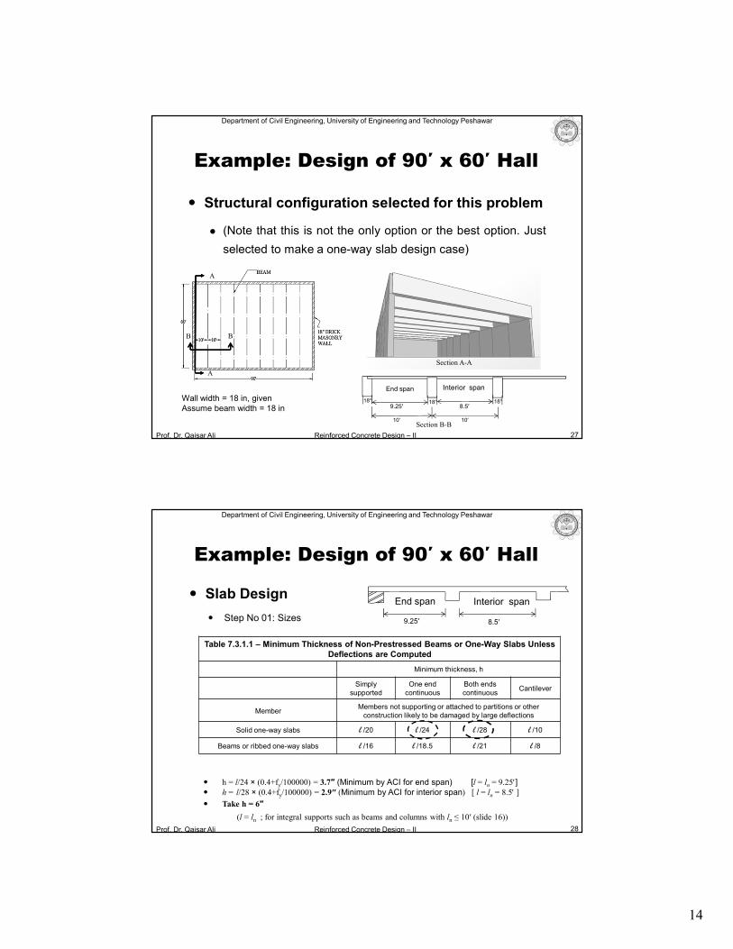
Structural configuration selected for this problem
(Note that this is not the only option or the best option. Just
selected to make a one-way slab design case)
27
Example: Design of 90′ x 60′ Hall
18′′
End span Interior span
9.25′ 8.5′18′′ 18′′Wall width = 18 in, given
Assume beam width = 18 in
10′ 10′
A
A
Section A-A
B B
Section B-B
Prof. Dr. Qaisar Ali Reinforced Concrete Design – II
Department of Civil Engineering, University of Engineering and Technology Peshawar
Table 7.3.1.1 – Minimum Thickness of Non-Prestressed Beams or One-Way Slabs Unless Deflections are Computed
Minimum thickness, h
Simplysupported
One end continuous
Both endscontinuous
Cantilever
MemberMembers not supporting or attached to partitions or other
construction likely to be damaged by large deflections
Solid one-way slabs l /20 l /24 l /28 l /10
Beams or ribbed one-way slabs l /16 l /18.5 l /21 l /8
Slab Design
Step No 01: Sizes
28
End span Interior span
9.25′ 8.5′
h = l/24 × (0.4+fy/100000) = 3.7″ (Minimum by ACI for end span) [l = ln = 9.25] h = l/28 × (0.4+fy/100000) = 2.9″ (Minimum by ACI for interior span) [ l = ln = 8.5 ]
Take h = 6″
(l = ln ; for integral supports such as beams and columns with ln ≤ 10′ (slide 16))
Example: Design of 90′ x 60′ Hall
15
Prof. Dr. Qaisar Ali Reinforced Concrete Design – II
Department of Civil Engineering, University of Engineering and Technology Peshawar
Slab Design
Step No 02: Loads
Factored Load (wu) = 1.2D.L + 1.6L.L
= 1.2 × 0.125 + 1.6 × 0.04 = 0.214 ksf
29
Table: Dead Loads
Material Thickness (in) g (kcf) Load = thickness × g (ksf)
Slab 6 0.15 (6/12) × 0.15 = 0.075
Mud 3 0.12 (3/12) × 0.12 = 0.03
Tile 2 0.12 (2/12) × 0.12= 0.02
Total 0.125 ksf
Example: Design of 90′ x 60′ Hall
Prof. Dr. Qaisar Ali Reinforced Concrete Design – II
Department of Civil Engineering, University of Engineering and Technology Peshawar
Slab Design
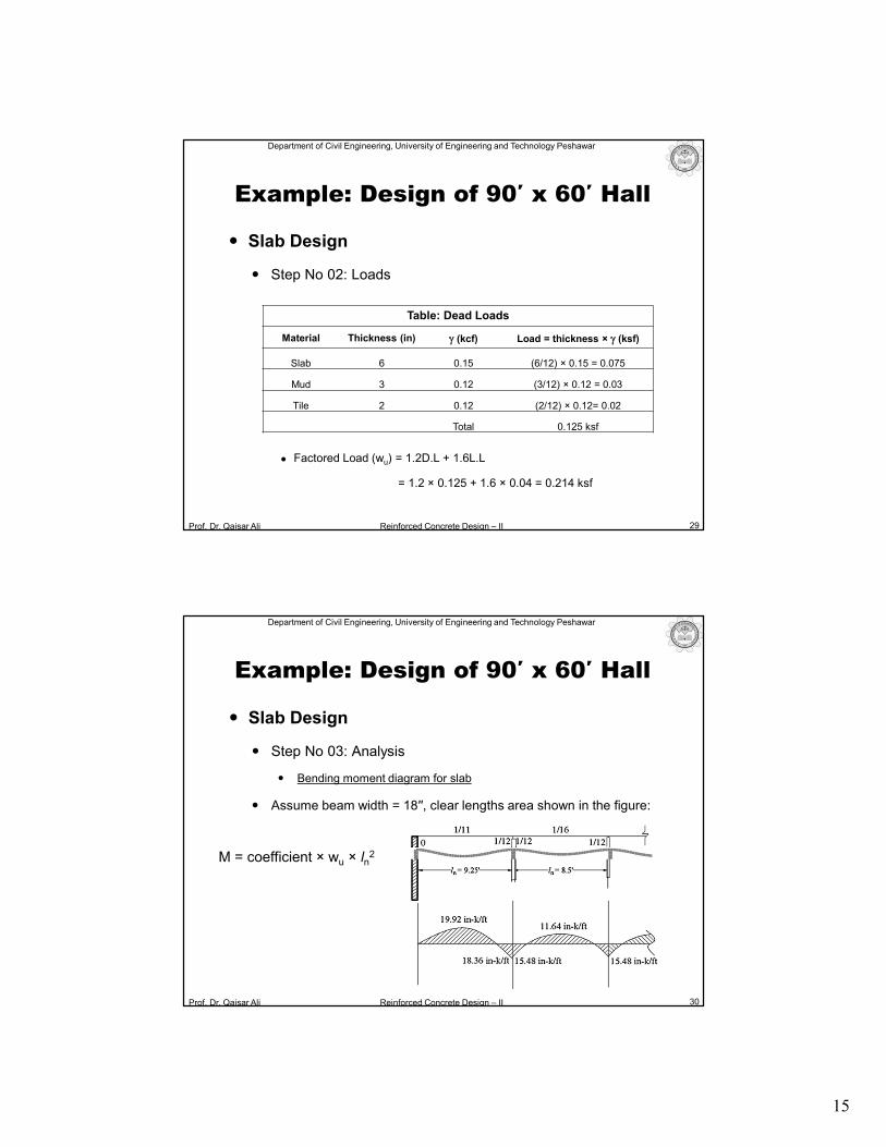
Step No 03: Analysis
Bending moment diagram for slab
Assume beam width = 18′′, clear lengths area shown in the figure:
30
M = coefficient × wu × ln2
Example: Design of 90′ x 60′ Hall
16
Prof. Dr. Qaisar Ali Reinforced Concrete Design – II
Department of Civil Engineering, University of Engineering and Technology Peshawar
Slab Design
Relative Stiffness of Slab and Beam- Slab Behavior
31
More stiff beams
Less stiff beams
Beam acting like pseudo support for slab
Slab
Wall (true) support
Example: Design of 90′ x 60′ Hall
Prof. Dr. Qaisar Ali Reinforced Concrete Design – II
Department of Civil Engineering, University of Engineering and Technology Peshawar
Slab Design
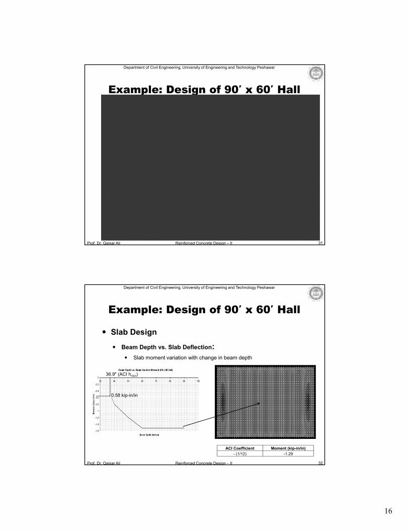
Beam Depth vs. Slab Deflection:
Slab moment variation with change in beam depth
32
ACI Coefficient Moment (kip-in/in)
- (1/12) -1.29
36.9″ (ACI hmin)
0.58 kip-in/in
Example: Design of 90′ x 60′ Hall
17
Prof. Dr. Qaisar Ali Reinforced Concrete Design – II
Department of Civil Engineering, University of Engineering and Technology Peshawar
Slab Design
Step No 04: Design
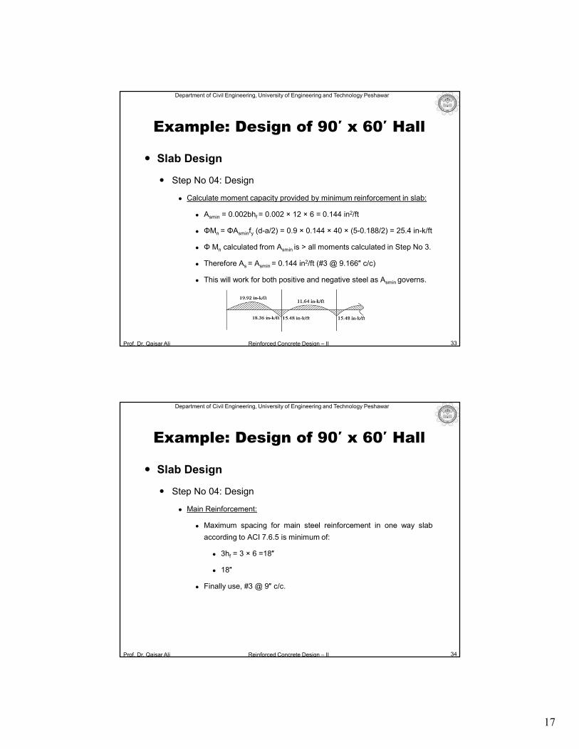
Calculate moment capacity provided by minimum reinforcement in slab:
Asmin = 0.002bhf = 0.002 × 12 × 6 = 0.144 in2/ft
ΦMn = ΦAsminfy (d-a/2) = 0.9 × 0.144 × 40 × (5-0.188/2) = 25.4 in-k/ft
Φ Mn calculated from Asmin is > all moments calculated in Step No 3.
Therefore As = Asmin = 0.144 in2/ft (#3 @ 9.166″ c/c)
This will work for both positive and negative steel as Asmin governs.
33
Example: Design of 90′ x 60′ Hall
Prof. Dr. Qaisar Ali Reinforced Concrete Design – II
Department of Civil Engineering, University of Engineering and Technology Peshawar
Slab Design
Step No 04: Design
Main Reinforcement:
Maximum spacing for main steel reinforcement in one way slab
according to ACI 7.6.5 is minimum of:
3hf = 3 × 6 =18″
18″
Finally use, #3 @ 9″ c/c.
34
Example: Design of 90′ x 60′ Hall
18
Prof. Dr. Qaisar Ali Reinforced Concrete Design – II
Department of Civil Engineering, University of Engineering and Technology Peshawar
Slab Design
Step No 04: Design
Shrinkage steel or temperature steel (Ast):
Ast = 0.002bhf Ast = 0.002 × 12 × 6 =0.144 in2/ft
Shrinkage reinforcement is same as main reinforcement, because:
Ast = Asmin = 0.144 in2
Maximum spacing for temperature steel reinforcement in one way slab
according to ACI 7.12.2.2 is minimum of:
5hf =5 × 6 =30″ OR 18″
Therefore 9″ spacing is O.K.
35
Example: Design of 90′ x 60′ Hall
Prof. Dr. Qaisar Ali Reinforced Concrete Design – II
Department of Civil Engineering, University of Engineering and Technology Peshawar
Slab Design
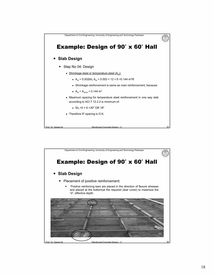
Placement of positive reinforcement:
Positive reinforcing bars are placed in the direction of flexure stressesand placed at the bottom(at the required clear cover) to maximize the“d”, effective depth.
36
Example: Design of 90′ x 60′ Hall
19
Prof. Dr. Qaisar Ali Reinforced Concrete Design – II
Department of Civil Engineering, University of Engineering and Technology Peshawar
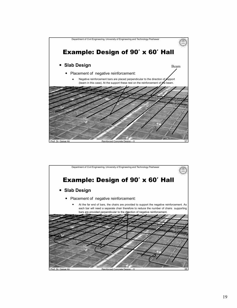
Negative reinforcement bars are placed perpendicular to the direction of support
(beam in this case). At the support these rest on the reinforcement of the beam.
Slab Design
Placement of negative reinforcement:
37
Example: Design of 90′ x 60′ Hall
Beam
Prof. Dr. Qaisar Ali Reinforced Concrete Design – II
Department of Civil Engineering, University of Engineering and Technology Peshawar
38
Example: Design of 90′ x 60′ Hall
Slab Design
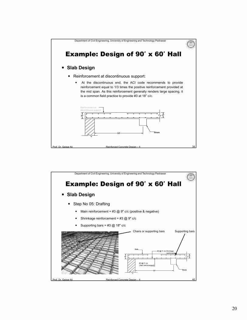
Placement of negative reinforcement:
At the far end of bars, the chairs are provided to support the negative reinforcement. As
each bar will need a separate chair therefore to reduce the number of chairs supporting
bars are provided perpendicular to the direction of negative reinforcement.
20
Prof. Dr. Qaisar Ali Reinforced Concrete Design – II
Department of Civil Engineering, University of Engineering and Technology Peshawar
Slab Design
Reinforcement at discontinuous support:
At the discontinuous end, the ACI code recommends to provide
reinforcement equal to 1/3 times the positive reinforcement provided at
the mid span. As this reinforcement generally renders large spacing, it
is a common field practice to provide #3 at 18” c/c.
39
Example: Design of 90′ x 60′ Hall
Prof. Dr. Qaisar Ali Reinforced Concrete Design – II
Department of Civil Engineering, University of Engineering and Technology Peshawar
Slab Design
Step No 05: Drafting
Main reinforcement = #3 @ 9″ c/c (positive & negative)
Shrinkage reinforcement = #3 @ 9″ c/c
Supporting bars = #3 @ 18″ c/c
40
Supporting bars
Example: Design of 90′ x 60′ Hall
Chairs or supporting bars
21
Prof. Dr. Qaisar Ali Reinforced Concrete Design – II
Department of Civil Engineering, University of Engineering and Technology Peshawar
Beam Design
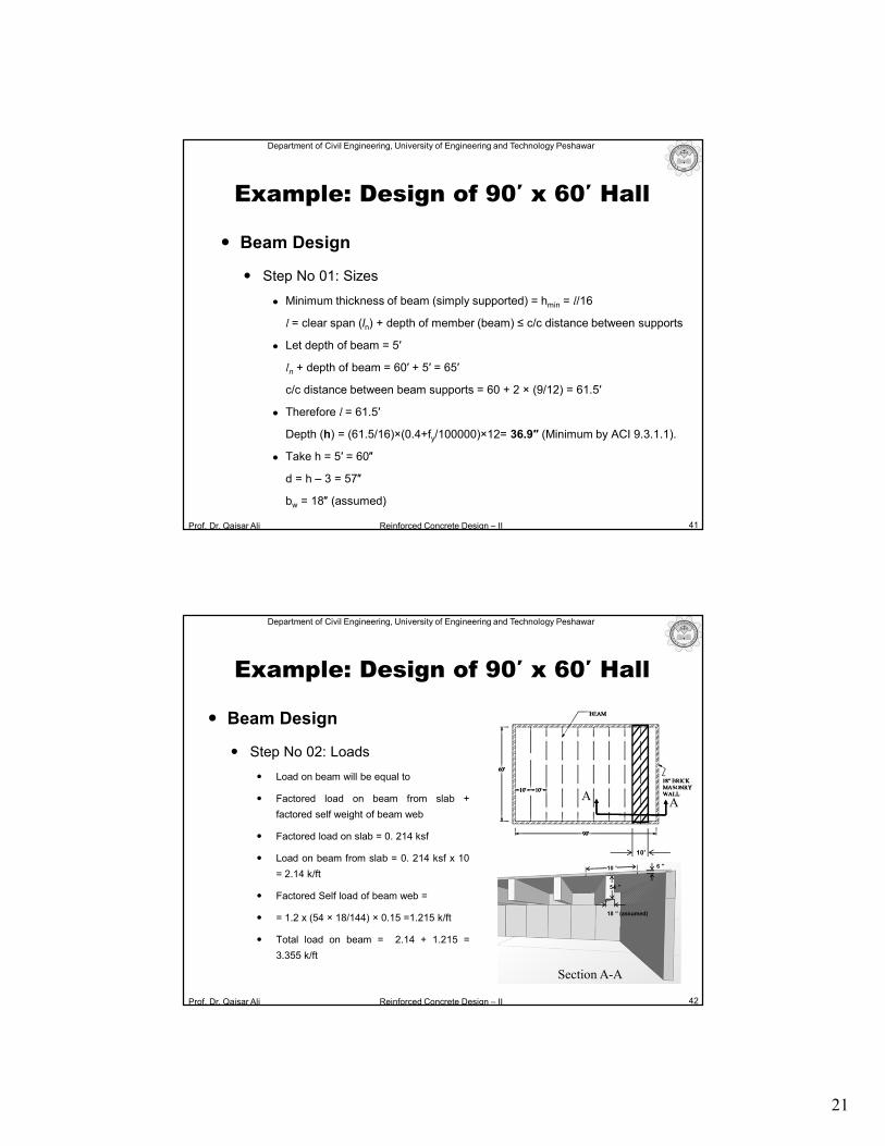
Step No 01: Sizes
Minimum thickness of beam (simply supported) = hmin = l/16
l = clear span (ln) + depth of member (beam) ≤ c/c distance between supports
Let depth of beam = 5′
ln + depth of beam = 60′ + 5′ = 65′
c/c distance between beam supports = 60 + 2 × (9/12) = 61.5′
Therefore l = 61.5′
Depth (h) = (61.5/16)×(0.4+fy/100000)×12= 36.9″ (Minimum by ACI 9.3.1.1).
Take h = 5′ = 60″
d = h – 3 = 57″
bw = 18″ (assumed)
41
Example: Design of 90′ x 60′ Hall
Prof. Dr. Qaisar Ali Reinforced Concrete Design – II
Department of Civil Engineering, University of Engineering and Technology Peshawar
Beam Design
Step No 02: Loads
Load on beam will be equal to
Factored load on beam from slab +
factored self weight of beam web
Factored load on slab = 0. 214 ksf
Load on beam from slab = 0. 214 ksf x 10
= 2.14 k/ft
Factored Self load of beam web =
= 1.2 x (54 × 18/144) × 0.15 =1.215 k/ft
Total load on beam = 2.14 + 1.215 =
3.355 k/ft
42
Example: Design of 90′ x 60′ Hall
10′
18 ′′ (assumed)
54 ′′
6 ′′10 ′
AA
Section A-A
22
Prof. Dr. Qaisar Ali Reinforced Concrete Design – II
Department of Civil Engineering, University of Engineering and Technology Peshawar
Beam Design
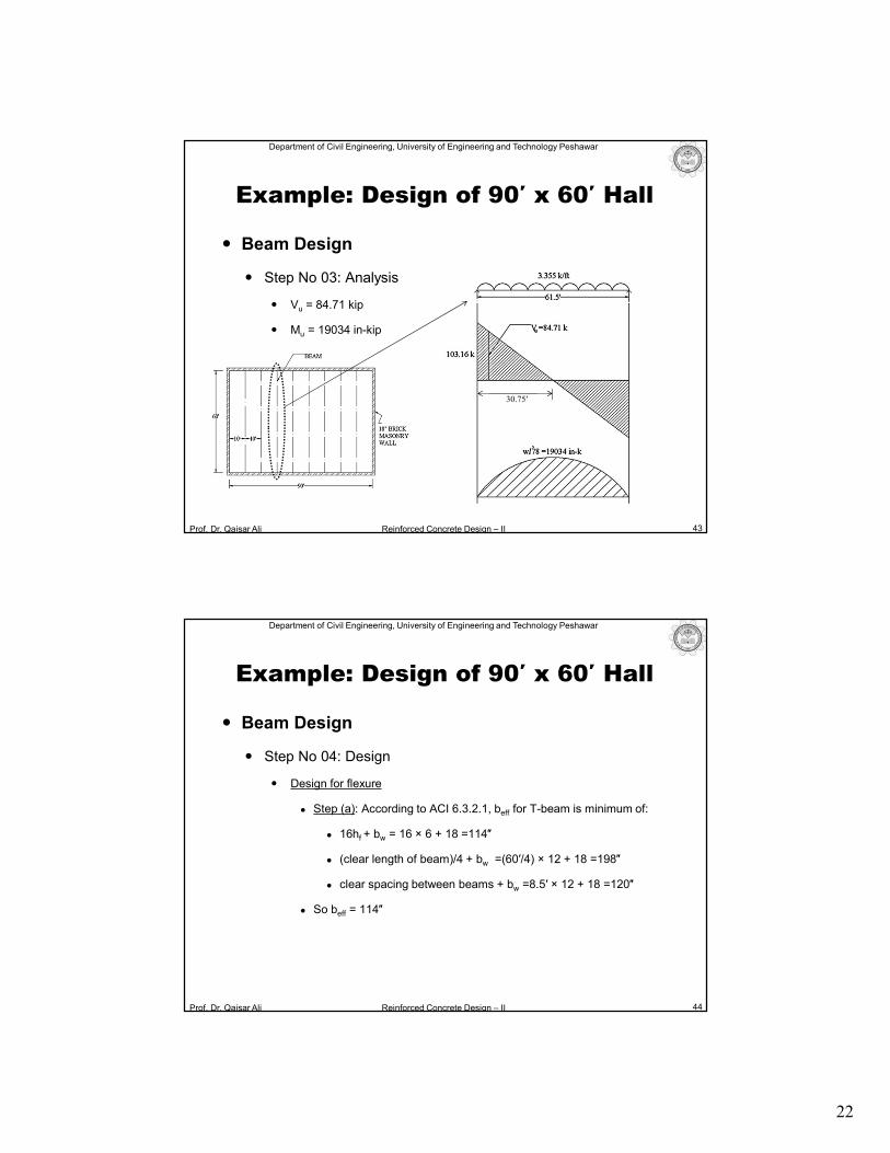
Step No 03: Analysis
Vu = 84.71 kip
Mu = 19034 in-kip
43
30.75′
Example: Design of 90′ x 60′ Hall
Prof. Dr. Qaisar Ali Reinforced Concrete Design – II
Department of Civil Engineering, University of Engineering and Technology Peshawar
Beam Design
Step No 04: Design
Design for flexure
Step (a): According to ACI 6.3.2.1, beff for T-beam is minimum of:
16hf + bw = 16 × 6 + 18 =114″
(clear length of beam)/4 + bw =(60′/4) × 12 + 18 =198″
clear spacing between beams + bw =8.5′ × 12 + 18 =120″
So beff = 114″
44
Example: Design of 90′ x 60′ Hall
23
Prof. Dr. Qaisar Ali Reinforced Concrete Design – II
Department of Civil Engineering, University of Engineering and Technology Peshawar
Beam Design
Step No 04: Design
Design for flexure
Step (b): Check if beam is to be designed as rectangular beam or T-beam.
Assume a = hf = 6″ and calculate As:
As =Mu/ {Φfy (d–a/2)} =19034/ {0.9 × 40 × (57–6/2)} = 9.79 in2
Re-calculate “a”:
a =Asfy/ (0.85fc′beff) =9.79 × 40/ (0.85 × 3 × 114) = 1.34″ < hf
Therefore design beam as rectangular beam.
After trials As = 9.38 in2 {Asmax = 20.83 in2 ;Asmin = 5.13 in2}
Therefore As = 9.38 in2 {12 #8 bars}
45
Example: Design of 90′ x 60′ Hall
Prof. Dr. Qaisar Ali Reinforced Concrete Design – II
Department of Civil Engineering, University of Engineering and Technology Peshawar
Beam Design
Step No 04: Design
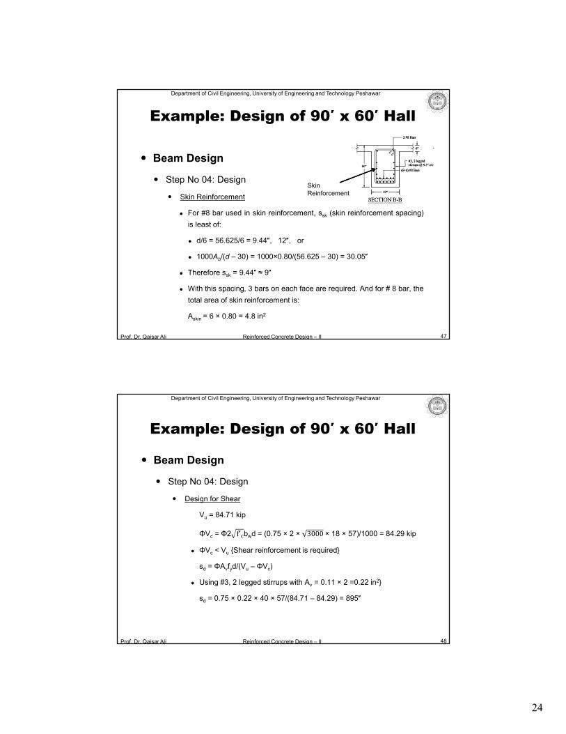
Skin Reinforcement : ACI 9.7.2.3
As the effective depth d of a beam is greater than 36 inches,
longitudinal skin reinforcement is required as per ACI 9.7.2.3.
Askin, = Main flexural reinforcement/2 = 9.60/2 = 4.8 in2
Range up to which skin reinforcement is provided:
d/2 = 56.625/2 = 28.3125″
46
Example: Design of 90′ x 60′ Hall
24
Prof. Dr. Qaisar Ali Reinforced Concrete Design – II
Department of Civil Engineering, University of Engineering and Technology Peshawar
Beam Design
Step No 04: Design
Skin Reinforcement
For #8 bar used in skin reinforcement, ssk (skin reinforcement spacing)
is least of:
d/6 = 56.625/6 = 9.44″, 12″, or
1000Ab/(d – 30) = 1000×0.80/(56.625 – 30) = 30.05″
Therefore ssk = 9.44″ ≈ 9″
With this spacing, 3 bars on each face are required. And for # 8 bar, the
total area of skin reinforcement is:
Askin = 6 × 0.80 = 4.8 in2
47
Example: Design of 90′ x 60′ Hall
Skin Reinforcement
Prof. Dr. Qaisar Ali Reinforced Concrete Design – II
Department of Civil Engineering, University of Engineering and Technology Peshawar
Beam Design
Step No 04: Design
Design for Shear
Vu = 84.71 kip
ΦVc = Φ2 f′�bwd = (0.75 × 2 × 3000 × 18 × 57)/1000 = 84.29 kip
ΦVc < Vu {Shear reinforcement is required}
sd = ΦAvfyd/(Vu – ΦVc)
Using #3, 2 legged stirrups with Av = 0.11 × 2 =0.22 in2}
sd = 0.75 × 0.22 × 40 × 57/(84.71 – 84.29) = 895″
48
Example: Design of 90′ x 60′ Hall
25
Prof. Dr. Qaisar Ali Reinforced Concrete Design – II
Department of Civil Engineering, University of Engineering and Technology Peshawar
Beam Design
Step No 04: Design
Design for Shear
Maximum spacing and minimum reinforcement requirement as
permitted by ACI 9.7.6.2.2 and 10.6.2.2 shall be minimum of:
Avfy/(50bw) =0.22 × 40000/(50 × 18) ≈ 9.5″
d/2 =57/2 =28.5″
24″
Avfy/ 0.75 f′� bw = 0.22 × 40000/ {(0.75 × 3000 × 18} = 11.90″
Therefore, smax = 9.5″
49
Example: Design of 90′ x 60′ Hall
Prof. Dr. Qaisar Ali Reinforced Concrete Design – II
Department of Civil Engineering, University of Engineering and Technology Peshawar
Beam Design
Step No 04: Design
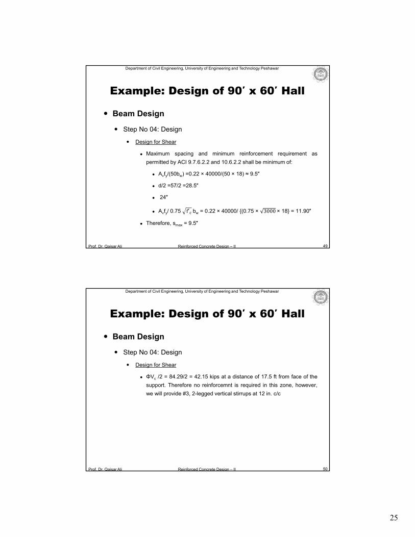
Design for Shear
ΦVc /2 = 84.29/2 = 42.15 kips at a distance of 17.5 ft from face of the
support. Therefore no reinforcemnt is required in this zone, however,
we will provide #3, 2-legged vertical stirrups at 12 in. c/c
50
Example: Design of 90′ x 60′ Hall
26
Prof. Dr. Qaisar Ali Reinforced Concrete Design – II
Department of Civil Engineering, University of Engineering and Technology Peshawar
Beam Design
Step No 04: Design
Design for Shear
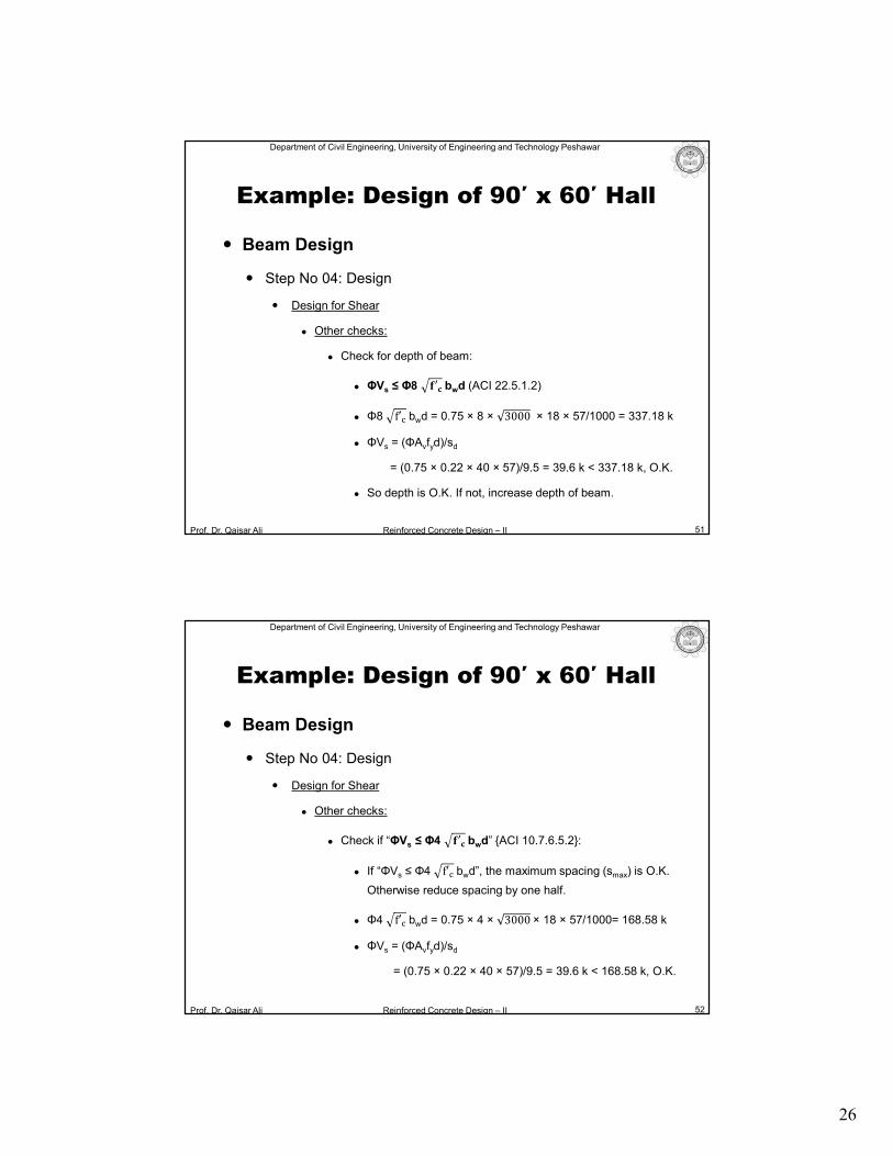
Other checks:
Check for depth of beam:
ΦVs ≤ Φ8 �′� bwd (ACI 22.5.1.2)
Φ8 f′� bwd = 0.75 × 8 × 3000 × 18 × 57/1000 = 337.18 k
ΦVs = (ΦAvfyd)/sd
= (0.75 × 0.22 × 40 × 57)/9.5 = 39.6 k < 337.18 k, O.K.
So depth is O.K. If not, increase depth of beam.
51
Example: Design of 90′ x 60′ Hall
Prof. Dr. Qaisar Ali Reinforced Concrete Design – II
Department of Civil Engineering, University of Engineering and Technology Peshawar
Beam Design
Step No 04: Design
Design for Shear
Other checks:
Check if “ΦVs ≤ Φ4 �′� bwd” {ACI 10.7.6.5.2}:
If “ΦVs ≤ Φ4 f′� bwd”, the maximum spacing (smax) is O.K.
Otherwise reduce spacing by one half.
Φ4 f′� bwd = 0.75 × 4 × 3000 × 18 × 57/1000= 168.58 k
ΦVs = (ΦAvfyd)/sd
= (0.75 × 0.22 × 40 × 57)/9.5 = 39.6 k < 168.58 k, O.K.
52
Example: Design of 90′ x 60′ Hall
27
Prof. Dr. Qaisar Ali Reinforced Concrete Design – II
Department of Civil Engineering, University of Engineering and Technology Peshawar
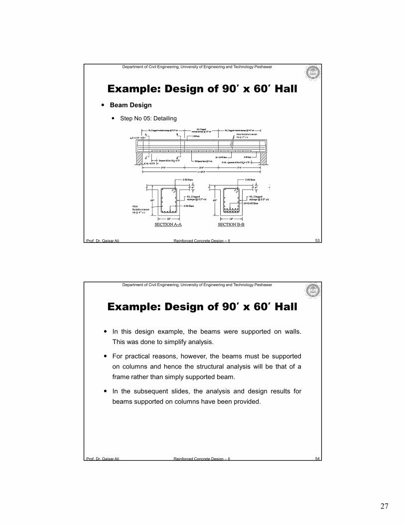
Beam Design
Step No 05: Detailing
53
Example: Design of 90′ x 60′ Hall
Prof. Dr. Qaisar Ali Reinforced Concrete Design – II
Department of Civil Engineering, University of Engineering and Technology Peshawar
54
Example: Design of 90′ x 60′ Hall
In this design example, the beams were supported on walls.
This was done to simplify analysis.
For practical reasons, however, the beams must be supported
on columns and hence the structural analysis will be that of a
frame rather than simply supported beam.
In the subsequent slides, the analysis and design results for
beams supported on columns have been provided.
28
Prof. Dr. Qaisar Ali Reinforced Concrete Design – II
Department of Civil Engineering, University of Engineering and Technology Peshawar
55
Example: Design of 90′ x 60′ Hall
Frame Analysis
3D model of the hall showing beams supported on columns.
Prof. Dr. Qaisar Ali Reinforced Concrete Design – II
Department of Civil Engineering, University of Engineering and Technology Peshawar
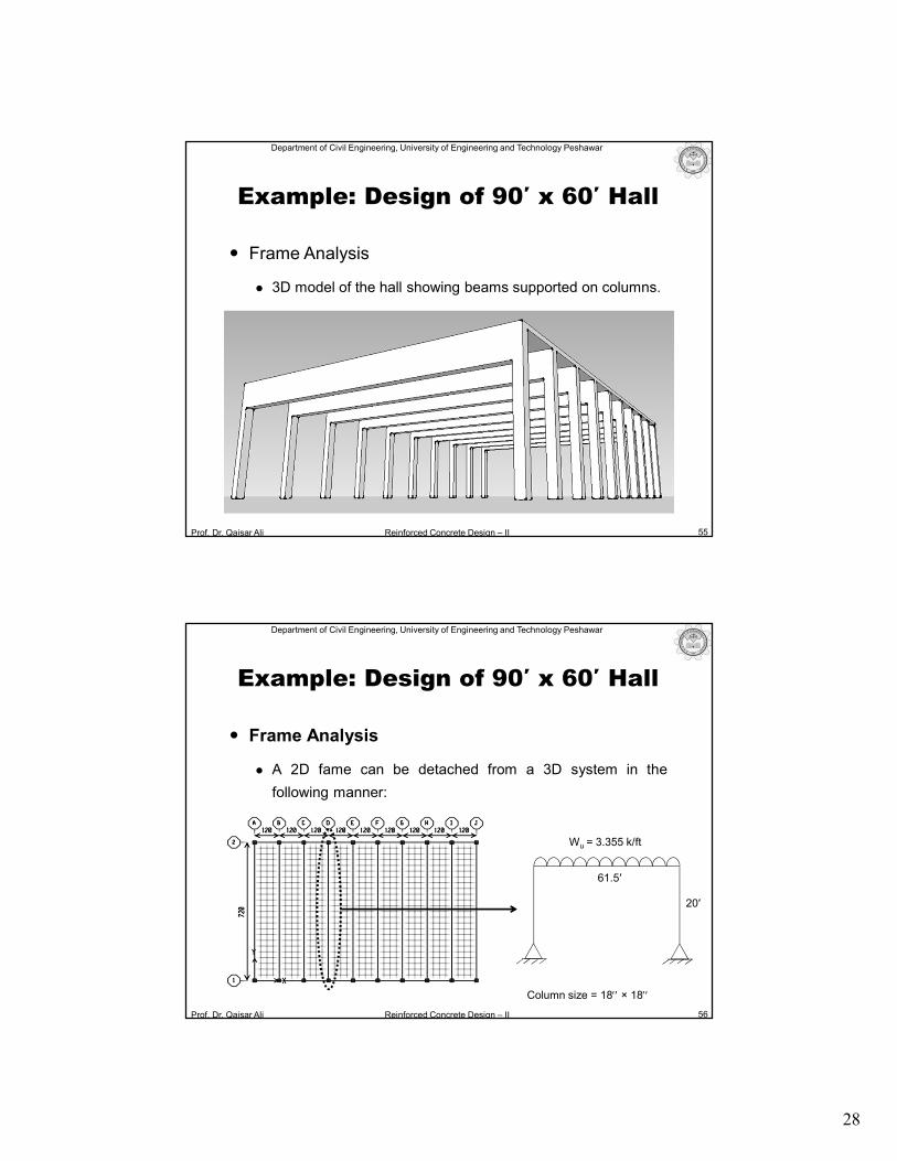
Frame Analysis
A 2D fame can be detached from a 3D system in the
following manner:
56
Example: Design of 90′ x 60′ Hall
61.5′
20′
Wu = 3.355 k/ft
Column size = 18 × 18
29
Prof. Dr. Qaisar Ali Reinforced Concrete Design – II
Department of Civil Engineering, University of Engineering and Technology Peshawar
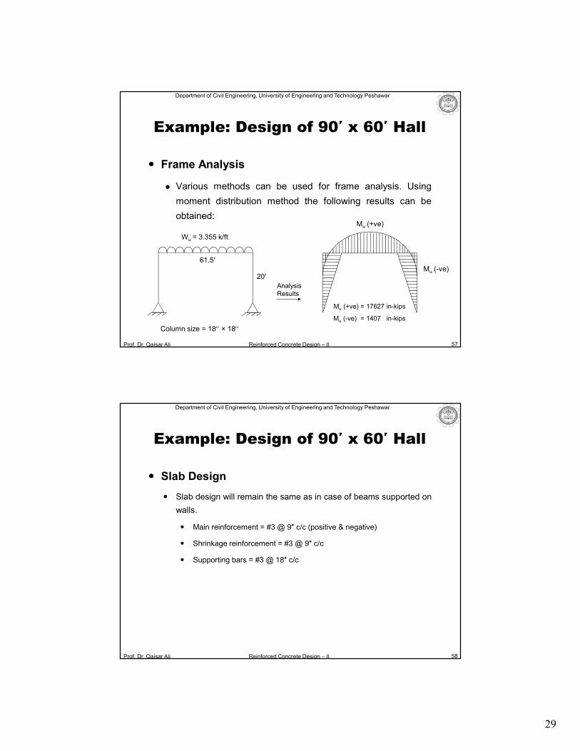
Frame Analysis
Various methods can be used for frame analysis. Using
moment distribution method the following results can be
obtained:
57
Example: Design of 90′ x 60′ Hall
20′
Analysis Results
Mu (+ve) = 17627 in-kips
Mu (-ve)
Mu (+ve)
Mu (-ve) = 1407 in-kips
61.5′
Wu = 3.355 k/ft
Column size = 18 × 18
Prof. Dr. Qaisar Ali Reinforced Concrete Design – II
Department of Civil Engineering, University of Engineering and Technology Peshawar
58
Example: Design of 90′ x 60′ Hall
Slab Design
Slab design will remain the same as in case of beams supported on
walls.
Main reinforcement = #3 @ 9″ c/c (positive & negative)
Shrinkage reinforcement = #3 @ 9″ c/c
Supporting bars = #3 @ 18″ c/c
30
Prof. Dr. Qaisar Ali Reinforced Concrete Design – II
Department of Civil Engineering, University of Engineering and Technology Peshawar
59
Example: Design of 90′ x 60′ Hall
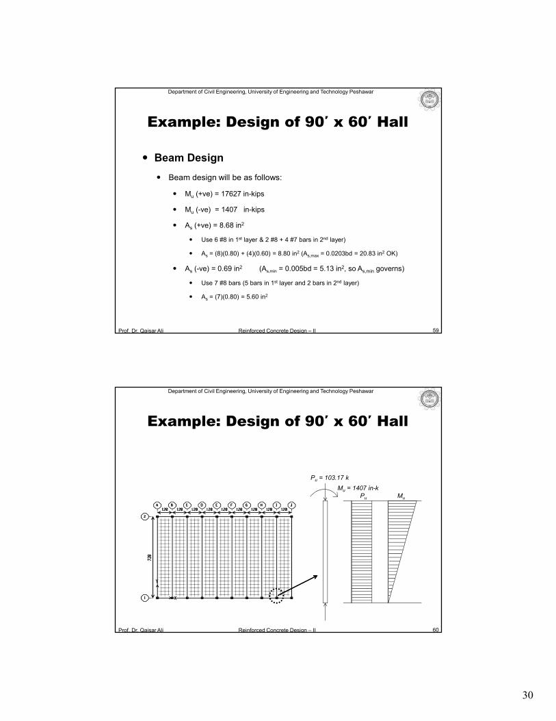
Beam Design
Beam design will be as follows:
Mu (+ve) = 17627 in-kips
Mu (-ve) = 1407 in-kips
As (+ve) = 8.68 in2
Use 6 #8 in 1st layer & 2 #8 + 4 #7 bars in 2nd layer)
As = (8)(0.80) + (4)(0.60) = 8.80 in2 (As,max = 0.0203bd = 20.83 in2 OK)
As (-ve) = 0.69 in2 (As,min = 0.005bd = 5.13 in2, so As,min governs)
Use 7 #8 bars (5 bars in 1st layer and 2 bars in 2nd layer)
As = (7)(0.80) = 5.60 in2
Prof. Dr. Qaisar Ali Reinforced Concrete Design – II
Department of Civil Engineering, University of Engineering and Technology Peshawar
60
Example: Design of 90′ x 60′ Hall
Pu = 103.17 k
Mu = 1407 in-kPu Mu
31
Prof. Dr. Qaisar Ali Reinforced Concrete Design – II
Department of Civil Engineering, University of Engineering and Technology Peshawar
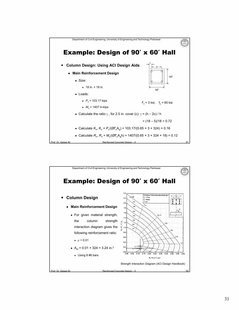
Column Design: Using ACI Design Aids
Main Reinforcement Design
Size:
18 in. × 18 in.
Loads:
Pu = 103.17 kips
Mu = 1407 in-kips
Calculate the ratio g , for 2.5 in. cover (c): g = (h – 2c) / h
= (18 – 5)/18 = 0.72
Calculate Kn, Kn = Pu/(Øf′cAg) = 103.17/(0.65 × 3 × 324) = 0.16
Calculate Rn, Rn = Mu/(Øf′cAgh) = 1407/(0.65 × 3 × 324 × 18) = 0.12
61
f′c = 3 ksi, fy = 60 ksi
18′′
18′′
gh
c
Example: Design of 90′ x 60′ Hall
Prof. Dr. Qaisar Ali Reinforced Concrete Design – II
Department of Civil Engineering, University of Engineering and Technology Peshawar
62
Example: Design of 90′ x 60′ Hall
Strength Interaction Diagram (ACI Design Handbook)
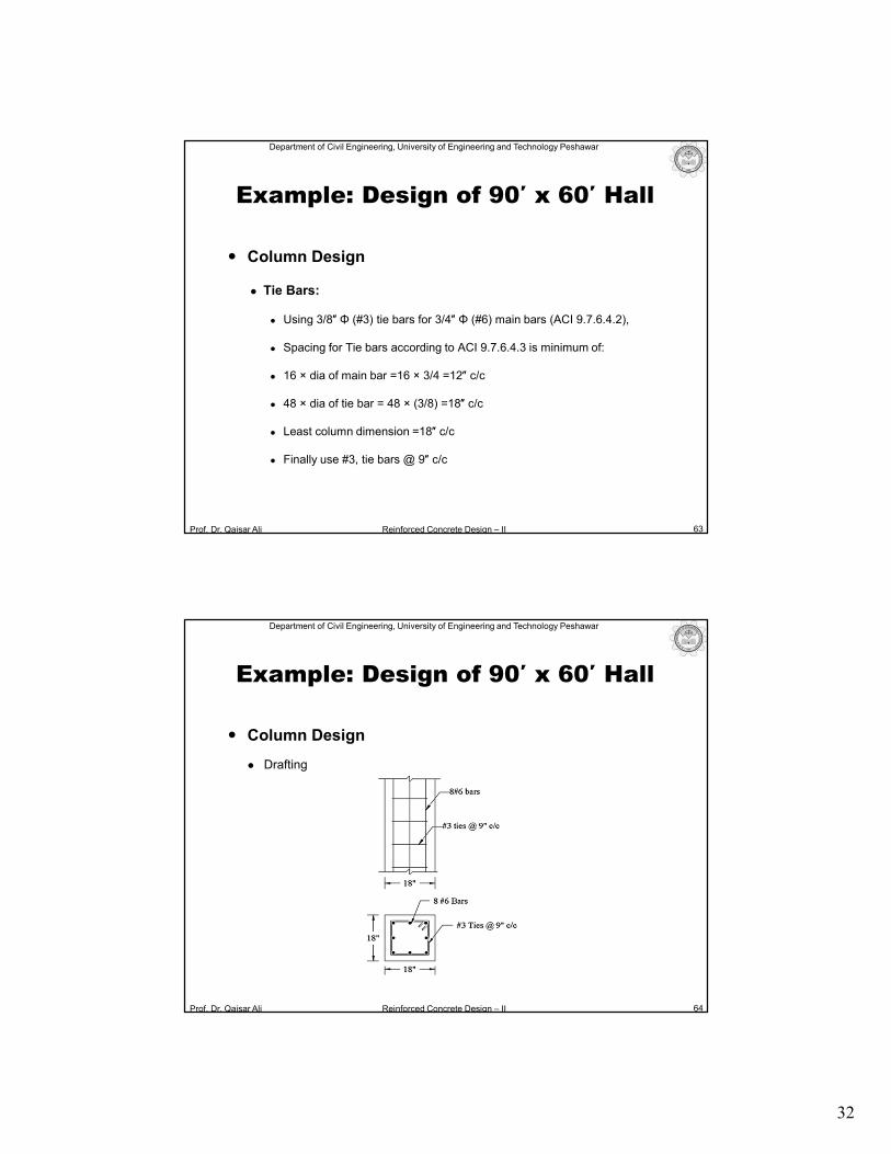
Column Design
Main Reinforcement Design
For given material strength,
the column strength
interaction diagram gives the
following reinforcement ratio:
r = 0.01
Ast = 0.01 × 324 = 3.24 in.2
Using 8 #6 bars
32
Prof. Dr. Qaisar Ali Reinforced Concrete Design – II
Department of Civil Engineering, University of Engineering and Technology Peshawar
Column Design
Tie Bars:
Using 3/8″ Φ (#3) tie bars for 3/4″ Φ (#6) main bars (ACI 9.7.6.4.2),
Spacing for Tie bars according to ACI 9.7.6.4.3 is minimum of:
16 × dia of main bar =16 × 3/4 =12″ c/c
48 × dia of tie bar = 48 × (3/8) =18″ c/c
Least column dimension =18″ c/c
Finally use #3, tie bars @ 9″ c/c
63
Example: Design of 90′ x 60′ Hall
Prof. Dr. Qaisar Ali Reinforced Concrete Design – II
Department of Civil Engineering, University of Engineering and Technology Peshawar
Column Design
Drafting
64
Example: Design of 90′ x 60′ Hall
33
Prof. Dr. Qaisar Ali Reinforced Concrete Design – II
Department of Civil Engineering, University of Engineering and Technology Peshawar
65
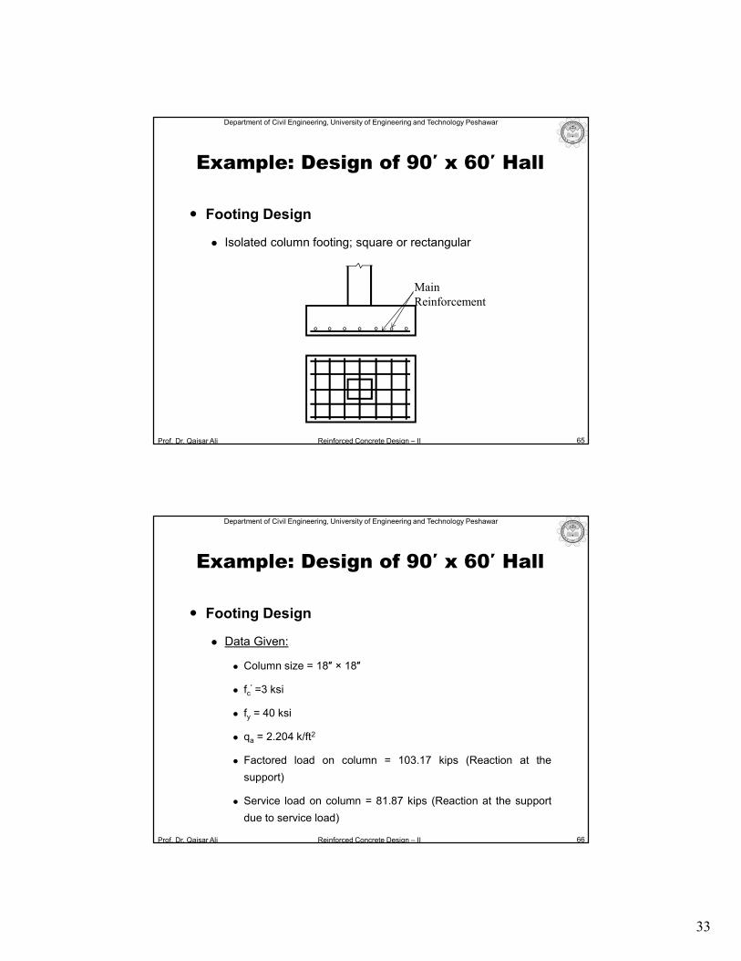
Main Reinforcement
Example: Design of 90′ x 60′ Hall
Footing Design
Isolated column footing; square or rectangular
Prof. Dr. Qaisar Ali Reinforced Concrete Design – II
Department of Civil Engineering, University of Engineering and Technology Peshawar
66
Example: Design of 90′ x 60′ Hall
Footing Design
Data Given:
Column size = 18″ × 18″
fc′ =3 ksi
fy = 40 ksi
qa = 2.204 k/ft2
Factored load on column = 103.17 kips (Reaction at the
support)
Service load on column = 81.87 kips (Reaction at the support
due to service load)
34
Prof. Dr. Qaisar Ali Reinforced Concrete Design – II
Department of Civil Engineering, University of Engineering and Technology Peshawar
67
Example: Design of 90′ x 60′ Hall
Footing Design
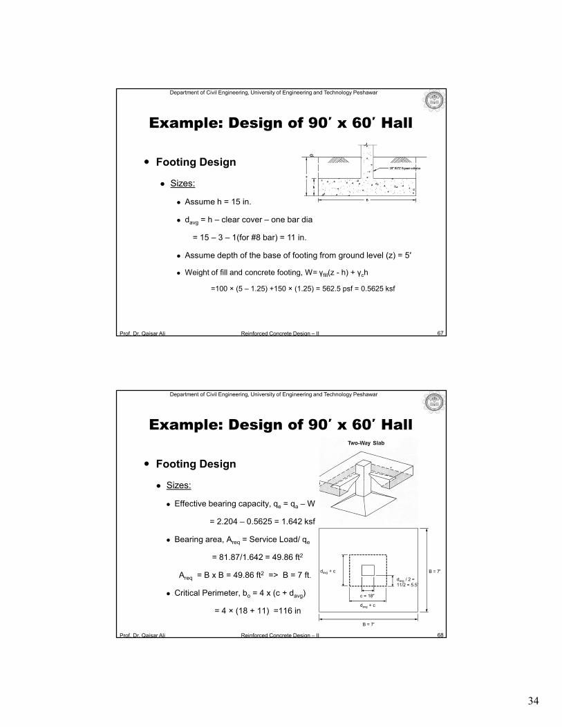
Sizes:
Assume h = 15 in.
davg = h – clear cover – one bar dia
= 15 – 3 – 1(for #8 bar) = 11 in.
Assume depth of the base of footing from ground level (z) = 5′
Weight of fill and concrete footing, W= γfill(z - h) + γch
=100 × (5 – 1.25) +150 × (1.25) = 562.5 psf = 0.5625 ksf
Prof. Dr. Qaisar Ali Reinforced Concrete Design – II
Department of Civil Engineering, University of Engineering and Technology Peshawar
Footing Design
Sizes:
Effective bearing capacity, qe = qa – W
= 2.204 – 0.5625 = 1.642 ksf
Bearing area, Areq = Service Load/ qe
= 81.87/1.642 = 49.86 ft2
Areq = B x B = 49.86 ft2 => B = 7 ft.
Critical Perimeter, bo = 4 x (c + davg)
= 4 × (18 + 11) =116 in
68
B = 7′
c = 18″
davg + c
davg / 2 = 11/2 = 5.5′
B = 7′ davg + c
Example: Design of 90′ x 60′ Hall
35
Prof. Dr. Qaisar Ali Reinforced Concrete Design – II
Department of Civil Engineering, University of Engineering and Technology Peshawar
69
Example: Design of 90′ x 60′ Hall
Footing Design
Loads:
qu (bearing pressure for strength design of footing):
qu = factored load on column / Areq = 103.17 / (7 × 7) = 2.105 ksf
Prof. Dr. Qaisar Ali Reinforced Concrete Design – II
Department of Civil Engineering, University of Engineering and Technology Peshawar
70
Example: Design of 90′ x 60′ Hall
B B
Footing Design
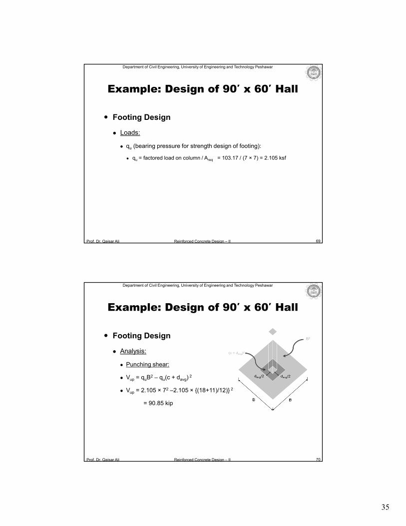
Analysis:
Punching shear:
Vup = quB2 – qu(c + davg)
2
Vup = 2.105 × 72 –2.105 × {(18+11)/12)} 2
= 90.85 kip
36
Prof. Dr. Qaisar Ali Reinforced Concrete Design – II
Department of Civil Engineering, University of Engineering and Technology Peshawar
Footing Design
Analysis:
Flexural Analysis:
Mu = quBk2/2
k = (B – c)/2 = (7 x 12 –18)/2
= 33 in = 2.75´
Mu = 2.105 × 7 × 2.75 × 2.75/2
= 55.72 ft-k
= 668.60 in-kip
71
Example: Design of 90′ x 60′ Hall
Critical Section
B B
ququ
Prof. Dr. Qaisar Ali Reinforced Concrete Design – II
Department of Civil Engineering, University of Engineering and Technology Peshawar
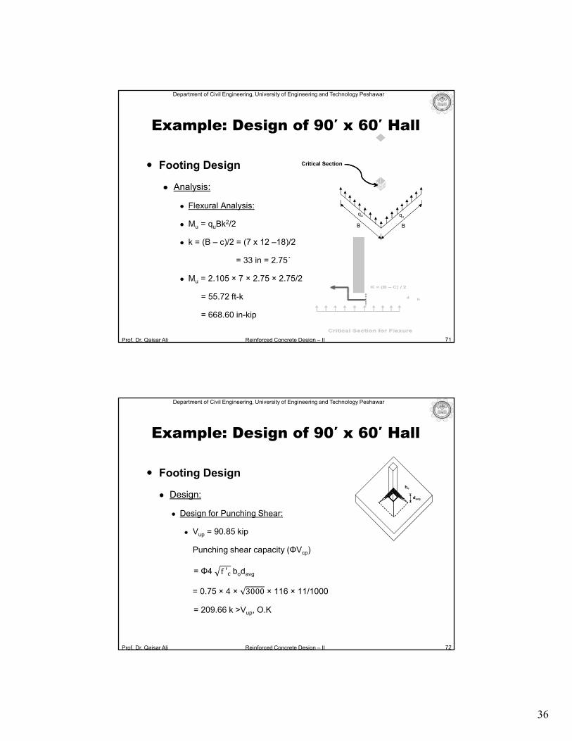
Footing Design
Design:
Design for Punching Shear:
Vup = 90.85 kip
Punching shear capacity (ΦVcp)
= Φ4 f ′� bodavg
= 0.75 × 4 × 3000 × 116 × 11/1000
= 209.66 k >Vup, O.K
72
Example: Design of 90′ x 60′ Hall
davg
bo
37
Prof. Dr. Qaisar Ali Reinforced Concrete Design – II
Department of Civil Engineering, University of Engineering and Technology Peshawar
73
Example: Design of 90′ x 60′ Hall
Footing Design
Design:
Design for Flexure:
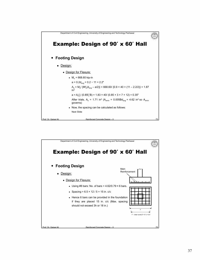
Mu = 668.60 kip-in
a = 0.2davg = 0.2 × 11 = 2.2″
As = Mu/ {Φfy(davg – a/2)} = 668.60/ {0.9 × 40 × (11 – 2.2/2)} = 1.87in2
a = Asfy/ (0.85fc′B) = 1.83 × 40/ (0.85 × 3 × 7 × 12) = 0.35″
After trials, As = 1.71 in2 (Asmin = 0.005Bdavg = 4.62 in2 so Asmin
governs)
Now, the spacing can be calculated as follows:
Next Slide
Prof. Dr. Qaisar Ali Reinforced Concrete Design – II
Department of Civil Engineering, University of Engineering and Technology Peshawar
Footing Design
Design:
Design for Flexure:
Using #8 bars: No. of bars = 4.62/0.79 ≈ 6 bars.
Spacing = 6.5 × 12 / 5 = 15 in. c/c
Hence 6 bars can be provided in the foundation
if they are placed 15 in. c/c (Max. spacing
should not exceed 3h or 18 in.)
74
Example: Design of 90′ x 60′ Hall
Main Reinforcement
7
7 - clear cover(3+3) = 6.5
38
Prof. Dr. Qaisar Ali Reinforced Concrete Design – II
Department of Civil Engineering, University of Engineering and Technology Peshawar
75
Example: Design of 90′ x 60′ Hall
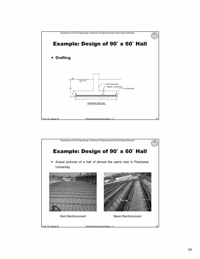
Drafting
Prof. Dr. Qaisar Ali Reinforced Concrete Design – II
Department of Civil Engineering, University of Engineering and Technology Peshawar
Actual pictures of a hall of almost the same size in Peshawar
University:
76
Example: Design of 90′ x 60′ Hall
Slab Reinforcement Beam Reinforcement
39
Prof. Dr. Qaisar Ali Reinforced Concrete Design – II
Department of Civil Engineering, University of Engineering and Technology Peshawar
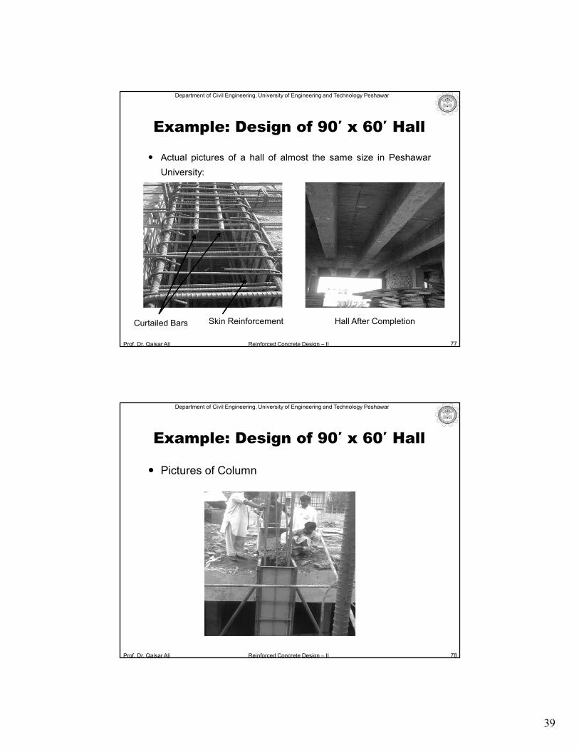
Actual pictures of a hall of almost the same size in Peshawar
University:
77
Example: Design of 90′ x 60′ Hall
Skin Reinforcement Hall After CompletionCurtailed Bars
Prof. Dr. Qaisar Ali Reinforced Concrete Design – II
Department of Civil Engineering, University of Engineering and Technology Peshawar
Pictures of Column
78
Example: Design of 90′ x 60′ Hall
40
Prof. Dr. Qaisar Ali Reinforced Concrete Design – II
Department of Civil Engineering, University of Engineering and Technology Peshawar
Case Studies
In the subsequent slides two case studies are carried out to
investigate the variation of moments in beams, moments and slab
thickness due to change in spacing between the beams.
79
Example: Design of 90′ x 60′ Hall
Spacing Between Beams
Prof. Dr. Qaisar Ali Reinforced Concrete Design – II
Department of Civil Engineering, University of Engineering and Technology Peshawar
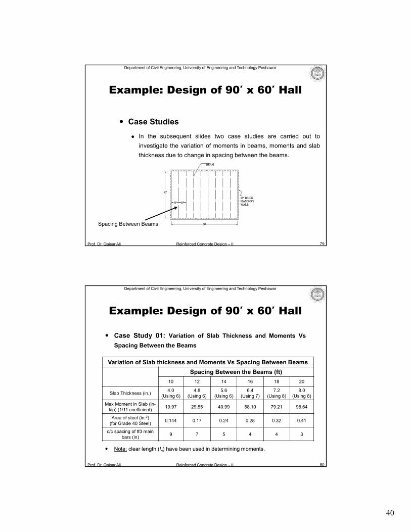
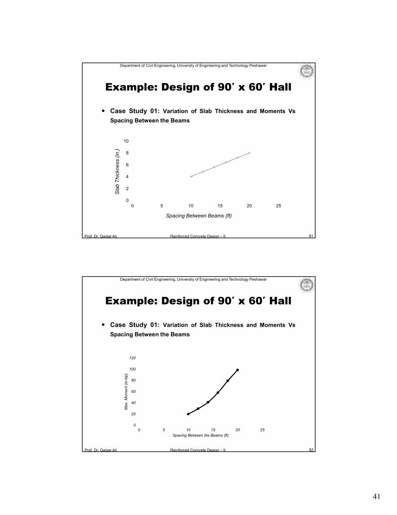
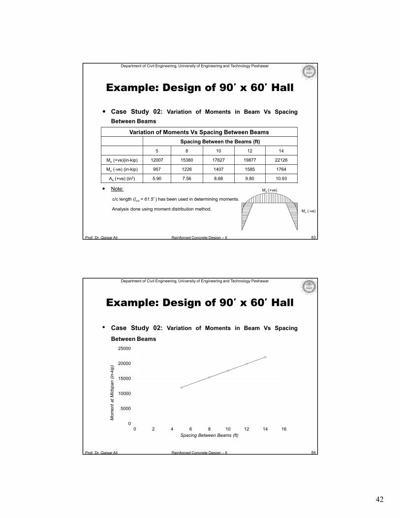
Case Study 01: Variation of Slab Thickness and Moments Vs
Spacing Between the Beams
Note: clear length (ln) have been used in determining moments.
80
Example: Design of 90′ x 60′ Hall
Variation of Slab thickness and Moments Vs Spacing Between Beams
Spacing Between the Beams (ft)
10 12 14 16 18 20
Slab Thickness (in.)4.0
(Using 6)4.8
(Using 6)5.6
(Using 6)6.4
(Using 7)7.2
(Using 8)8.0
(Using 8)
Max Moment in Slab (in-kip) (1/11 coefficient)
19.97 29.55 40.99 58.10 79.21 98.64
Area of steel (in.2)(for Grade 40 Steel)
0.144 0.17 0.24 0.28 0.32 0.41
c/c spacing of #3 main bars (in)
9 7 5 4 4 3
41
Prof. Dr. Qaisar Ali Reinforced Concrete Design – II
Department of Civil Engineering, University of Engineering and Technology Peshawar
Case Study 01: Variation of Slab Thickness and Moments Vs
Spacing Between the Beams
81
Example: Design of 90′ x 60′ Hall
0
2
4
6
8
10
0 5 10 15 20 25
Sla
b T
hic
kn
ess (
in.)
Spacing Between Beams (ft)
Prof. Dr. Qaisar Ali Reinforced Concrete Design – II
Department of Civil Engineering, University of Engineering and Technology Peshawar
Case Study 01: Variation of Slab Thickness and Moments Vs
Spacing Between the Beams
82
Example: Design of 90′ x 60′ Hall
0
20
40
60
80
100
120
0 5 10 15 20 25
Ma
x. M
om
ent (in
-kip
)
Spacing Between the Beams (ft)
42
Prof. Dr. Qaisar Ali Reinforced Concrete Design – II
Department of Civil Engineering, University of Engineering and Technology Peshawar
83
Example: Design of 90′ x 60′ Hall
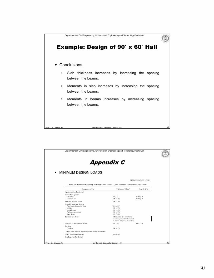
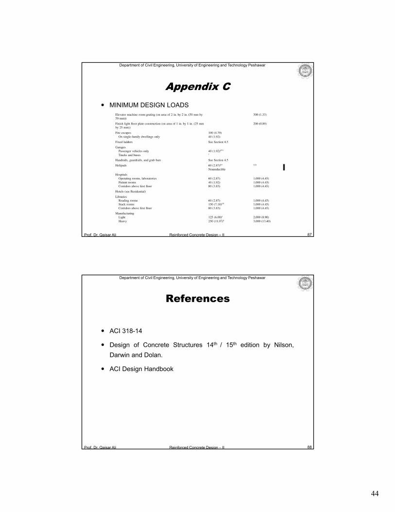
Variation of Moments Vs Spacing Between Beams
Spacing Between the Beams (ft)
5 8 10 12 14
Mu (+ve)(in-kip) 12007 15380 17627 19877 22126
Mu (-ve) (in-kip) 957 1226 1407 1585 1764
As (+ve) (in2) 5.90 7.56 8.68 9.80 10.93
Mu (-ve)
Mu (+ve)
Case Study 02: Variation of Moments in Beam Vs Spacing
Between Beams
Note:
c/c length (lc/c = 61.5′ ) has been used in determining moments.
Analysis done using moment distribution method.
Prof. Dr. Qaisar Ali Reinforced Concrete Design – II
Department of Civil Engineering, University of Engineering and Technology Peshawar
84
0
5000
10000
15000
20000
25000
0 2 4 6 8 10 12 14 16
Mom
ent
at
Mid
span
(in-k
ip)
Spacing Between Beams (ft)
Example: Design of 90′ x 60′ Hall
• Case Study 02: Variation of Moments in Beam Vs Spacing
Between Beams
43
Prof. Dr. Qaisar Ali Reinforced Concrete Design – II
Department of Civil Engineering, University of Engineering and Technology Peshawar
Conclusions
1. Slab thickness increases by increasing the spacing
between the beams.
2. Moments in slab increases by increasing the spacing
between the beams.
3. Moments in beams increases by increasing spacing
between the beams.
85
Example: Design of 90′ x 60′ Hall
Prof. Dr. Qaisar Ali Reinforced Concrete Design – II
Department of Civil Engineering, University of Engineering and Technology Peshawar
86
Appendix C
MINIMUM DESIGN LOADS
44
Prof. Dr. Qaisar Ali Reinforced Concrete Design – II
Department of Civil Engineering, University of Engineering and Technology Peshawar
Go to slide no 14
87
Appendix C
MINIMUM DESIGN LOADS
Prof. Dr. Qaisar Ali Reinforced Concrete Design – II
Department of Civil Engineering, University of Engineering and Technology Peshawar
References
88
ACI 318-14
Design of Concrete Structures 14th / 15th edition by Nilson,
Darwin and Dolan.
ACI Design Handbook
45
Prof. Dr. Qaisar Ali Reinforced Concrete Design – II
Department of Civil Engineering, University of Engineering and Technology Peshawar
The End
89