Embed Size (px)
Citation preview

Submit Manuscript | http://medcraveonline.com
IntroductionTraditional waterfront construction materials often have a
multitude of problems due to the harsh environmental conditions. On the shoreline, retaining walls are commonly used to prevent shoreline erosion and maintain the earth’s stability. Traditional materials used are steel, reinforced concrete, and timber. Steel and reinforced concrete will deteriorate due to corrosion and spalling. Timber requires chemical treatment and can be attacked by marine borers. To respond to these major issues, several alternative materials have emerged for marine waterfront construction applications, these materials include plastic and composite materials. One viable option for retaining wall material is WPC. WPCs are a mixture of a thermoplastic resin and wood fibers. To date WPC has been used successfully in many applications including decking, railings, and fencing. The two main advantages of WPC are the material properties (e.g. durability, lightweight, recyclable) and its ability to be produced in a wide range of geometric configurations. These advantages can be utilized by applying the material to more innovative applications such as retaining walls in marine structures.1–3
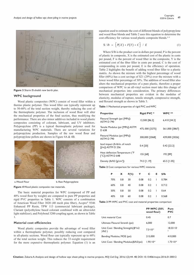
The Sharm El-sheikh port the case study a shown in Figure 1, its construction date 1963, land area equal 0,162km2, channel length equal 40m depth, number of quays equal 1,625m Long, between 5 to 8m depth, number of scaffold equal 2 of 180m long, and the capacity: 100,000 passenger / tourist.
The overall objectives of this research can be divided into two categories: First making a finite element model for the Sharm El-shikh Berth according to Figures 1‒3 and comparing the results of WPC and Steel Sheet pile wall, and the second comparing the cost of WPC, PVC and Steel Sheet pile.
Figure 1 Sharm El-sheikh master plan.
Figure 2 Sharm El-sheikh new berth x-section.
MOJ Civil Eng. 2016;1(2):44‒48. 44© 2016 Zakaria. This is an open access article distributed under the terms of the Creative Commons Attribution License, which permits unrestricted use, distribution, and build upon your work non-commercially.
Analysis and design of hollow wpc sheet piling in marine projects
Volume 1 Issue 2 - 2016
Ayman ZakariaDepartment f Civil Engineering, University of Ain Sham, Egypt
Correspondence: Ayman Zakaria, Department of Civil Engineering, University of Ain Sham, Egypt, Tel +2 01001010552, Email [email protected] Received: October 24, 2016 | Published: November 23, 2016
Abstract
Traditional waterfront construction materials often have a multitude of problems due to the harsh environmental conditions. On the shoreline, retaining walls are commonly used to prevent shoreline erosion and maintain the earth’s stability. Traditional materials used are steel, reinforced concrete, and timber. Steel and reinforced concrete will deteriorate due to corrosion and spelling. Timber requires chemical treatment and can be attacked by marine borers. To respond to these major issues, several alternative materials have emerged for marine waterfront construction applications, these materials include plastic and composite materials. One viable option for retaining wall material is WPC. WPCs are a mixture of a thermoplastic resin and wood fibers. To date WPC has been used successfully in many applications including decking, railings, and fencing. The two main advantages of WPC are the material properties (e.g. durability, lightweight, recyclable) and its ability to be produced in a wide range of geometric configurations. These advantages can be utilized by applying the material to more innovative applications such as retaining walls in marine structures.
The Sharm El-sheikh port the case study, its construction date 1963, land area equal 0,162km2, channel length equal 40m depth, number of quays equal 1,625m Long, between 5 to 8m depth, number of scaffold equal 2 of 180m long, and the capacity: 100,000 passenger/tourist. The overall objectives of this research can be divided into two categories: First making a finite element model for the Sharm El-shikh Berth and comparing the results of WPC and Steel Sheet pile wall, and the second comparing the cost of WPC and Steel Sheet pile walls.
MOJ Civil Engineering
Research Article Open Access
Analysis and design of hollow wpc sheet piling in marine projects 45Copyright:
©2016 Zakaria
Citation: Zakaria A. Analysis and design of hollow wpc sheet piling in marine projects. MOJ Civil Eng. 2016;1(2):44‒48. DOI: 10.15406/mojce.2016.01.00012
Figure 3 Sharm El-sheikh new berth plan.
WPC background
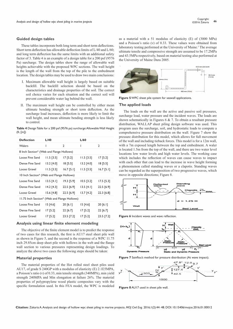
Wood plastic composites (WPC) consist of wood filler within a thermo plastic polymer. This wood filler can typically represent up to 50-60% of the total section weight, thereby reducing the cost of the thermoplastic polymer. The inclusion of wood flour will alter the mechanical properties of the final section, thus modifying the performance. There are also minor additives included in wood plastic composites consisting of colorant, lubricant, and UV inhibitors. Polypropylene (PP) is a typical thermoplastic polymer used for manufacturing WPC materials. There are several variations for polypropylene production. Samples of the raw wood flour and polypropylene pellets are shown in Figure 4A & 4B.
a. Wood Flour b. Raw Polypropylene
Figure 4 Wood plastic composite raw materials.
The basic material properties for WPC (composed of PP and 40% wood floor by weight) are compared to pure PP properties and rigid PVC properties in Table 1. WPC consists of a combination of American Wood Fiber 3020 (40 mesh pine fiber), Accpro® 9346 Enhanced PP Resin, TPW 113 (commercial lubricant package), Clariant (polyethylene based colorant combined with an ultraviolet light stabilizer), and Polybond 3200 coupling agent, as shown in Table 1.
Material cost efficiencies
Wood plastic composites provide the advantage of wood filler within a thermoplastic polymer, possibly reducing cost compared to all-plastic sections. Wood flour can typically represent up to 60% of the total section weight. This reduces the 33-weight requirement for the more expensive thermoplastic polymer. Equation (1) is an
equation used to estimate the cost of different blends of polypropylene and wood flour blends and Table 2 uses this equation to determine the cost efficiency for various wood plastic composite blends.4–6
( ) ( )$ / / lb P X F Y C E = + + (1)
Where $/lb is the product cost in dollars per pound, P is the percent of plastic in composite, X is the estimated cost of the plastic in cents per pound, F is the percent of wood fiber in the composite, Y is the estimated cost of the fiber filler in cents per pound, C is the cost of compounding in cents per pound, E is the efficiency of operation. Table 2 highlights the benefit of adding wood fiber filler to a plastic matrix. As shown the mixture with the highest percentage of wood filler (60%) has a cost savings of $21 (29%) over the mixture with a lower wood filler percentage of 30%. The addition of wood filler also alters the mechanical properties of a pure plastic, therefore a proper comparison of WPC to an all-vinyl section must take this change of mechanical properties into consideration. The primary differences between mechanical properties are evident in the modulus of elasticity, modulus of rupture, tensile strength, compressive strength, and flexural strength as shown in Table 3.
Table 1 Mechanical properties of rigid PVC and WPC
Properties Rigid PVC * WPC **
Flexural Strength (psi [MPa]) ASTM D 790
12,500 [86.2] 6,410 [44.2]
Tensile Modulus (psi [MPa]) ASTM D 638
475, 000 [3275] 561,000 [3867]
Flexural Modulus (psi [MPa]) ASTM D 790
300,000 [2068] 439,000 [3026]
Izod impact (ft-lb/in. of notch [J/m]) ASTM D 256
0.4 [20] 0.42 [22.2]
Heat deflection Temperature (°F [°C]) ASTM D 648
155 [68] 192 [89]
Density (lb/ft3 [g/cm3]) 74.3 [1.19] 65.5 [1.05]
Table 2 Cost comparison for various WPC mixtures
P X F(%) Y C E $/lb
70% 0.8 30 0.08 0.2 1 0.784
60% 0.8 40 0.08 0.2 1 0.712
50% 0.8 50 0.08 0.2 1 0.64
40% 0.8 60 0.08 0.2 1 0.568
Table 3 PP-WPC and PVC cost and material properties comparison
PP-WPC (50% wood flour)
Pure PVC
Unit material Cost 0.45 0.7
Ultimate Flexural Strenth (psi) 6,000 12,000
Unit Cost / Bending Strength(($*in2 )/lb2 ) 7.5ˣ10-5 18.55ˣ10-
5
Bending Modulus, MOE (psi) 215,000 410,000
Unit Cost / Bending Modulus($/ft3/psi) 1.95ˣ10-6 1.75ˣ10-6
Analysis and design of hollow wpc sheet piling in marine projects 46Copyright:
©2016 Zakaria
Citation: Zakaria A. Analysis and design of hollow wpc sheet piling in marine projects. MOJ Civil Eng. 2016;1(2):44‒48. DOI: 10.15406/mojce.2016.01.00012
Guided design tables
These tables incorporate both long term and short term deflections. Short term deflection has allowable deflection limits of L/40 and L/60; and long term deflection has the same limits with an additional safety factor of 3. Table 4 is an example of a design table for a 200 psf (9576 Pa) surcharge. The design tables show the range of allowable wall heights achievable with the proposed WPC sections. The wall height is the length of the wall from the top of the pile to the embedment location. The design tables may be used to draw two main conclusions:
I. Maximum allowable wall height is largely based on suitable backfill. The backfill selection should be based on the characteristics and drainage properties of the soil. The correct soil choice varies for each situation and the correct soil will prevent considerable water lag behind the wall.
II. The maximum wall height can be controlled by either mean ultimate bending strength or short term deflection. As the surcharge load increases, deflection is more likely to limit the wall height, and mean ultimate bending strength is less likely to control.
Table 4 Design Table for a 200 psf (9576 pa) surcharge: Allowable Wall Height (ft. [m])
Deflection L/40 L/60
Walers 1 2 1 2
8 Inch Section* (Web and Flange Hollows)
Loose Fine Sand 11.5 [3.5] 17 [5.2] 11.5 [3.5] 17 [5.2]
Dense Fine Sand 13.2 [4.0] 18 [5.5] 13.2 [4.0] 18 [5.5]
Loose Gravel 11.5 [3.5] 16.7 [5.1] 11.5 [3.5] 16.7 [5.1]
10 Inch Section* (Web and Flange Hollows)
Loose Fine Sand 13.5 [4.1] 19.3 [5.9] 10.5 [3.2] 17.5 [5.3]
Dense Fine Sand 14.2 [4.3] 22.5 [6.9] 13.5 [4.1] 22.5 [6.9]
Loose Gravel 15.6 [4.8] 22.5 [6.9] 13.7 [4.2] 22.3 [6.8]
11.75 Inch Section* (Web and Flange Hollows)
Loose Fine Sand 15 [4.6] 20 [6.1] 15 [4.6] 20 [6.1]
Dense Fine Sand 17 [5.2] 22 [6.7] 17 [5.2] 22 [6.7]
Loose Gravel 17 [5.2] 23.5 [7.2] 17 [5.2] 23.5 [7.2]
Analysis using linear finite element modeling
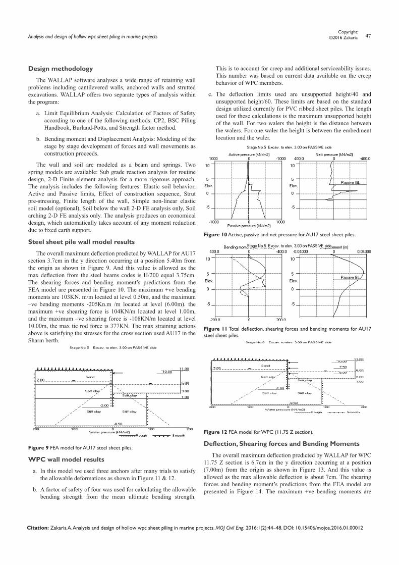
The objective of the finite element model is to predict the response of two cases for this research, the first is AU17 steel sheet pile wall as shown in Figure 5, and the second is the response of a WPC 11.75 inch 29.85cm deep sheet pile with hollows in the web and the flange wall section to various pressures representing design loadings. To analyze the above two cases the following steps should be taken:
Material properties
The material properties of the Hot rolled steel sheet piles used AU17, of grade S 240GP with a modulus of elasticity (E) 2.1E5MPA, a Poisson’s ratio (ν) of 0.33, min tensile strength (340MPA), min yield strength 240MPA and Min elongation at failure 26%. The material properties of polypropylene wood plastic composites vary with the specific formulation used. In this FEA model, the WPC is modeled
as a material with a 51 modulus of elasticity (E) of (3000 MPa) and a Poisson’s ratio (ν) of 0.33. These values were obtained from laboratory testing performed at the University of Maine.5 The average ultimate tensile and compressive strength are assumed to be 17.2MPa and 43.5MPa respectively, based on material testing also performed at the University of Maine Dura 2005.
Figure 5 WPC sheet pile system for seawall applications.
The applied loads
The loads on the wall are the active and passive soil pressures, surcharge load, water pressure and the incident waves. The loads are shown schematically in Figures 6 & 7. To obtain a resultant pressure distribution, WALLAP sheet piling design software was used. This program uses the surcharge, soil, and hydrostatic loads to compute a comprehensive pressure distribution on the wall. Figure 7 show the pressure distribution for this model, which allows for full movement of the wall and including tieback forces. This model is for a 12m wall, with a 7m exposed length between the top and embedment. A waler is located 1.5m from the top of the wall, and there are two water level locations low water levels and high water levels. The working case which includes the reflection of waves can cause waves to impact with each other that can lead to the increase in wave height forming a phenomenon called standing waves or a clapotis. Standing waves can be regarded as the superposition of two progressive waves, which move in opposite directions; Figure 8.
Figure 6 Incident waves and wave reflection.
Figure 7 Sainflou’s method for pressure distribution (At wave impact).
Figure 8 AU17 used in sheet pile wall.
Analysis and design of hollow wpc sheet piling in marine projects 47Copyright:
©2016 Zakaria
Citation: Zakaria A. Analysis and design of hollow wpc sheet piling in marine projects. MOJ Civil Eng. 2016;1(2):44‒48. DOI: 10.15406/mojce.2016.01.00012
Design methodology
The WALLAP software analyses a wide range of retaining wall problems including cantilevered walls, anchored walls and strutted excavations. WALLAP offers two separate types of analysis within the program:
a. Limit Equilibrium Analysis: Calculation of Factors of Safety according to one of the following methods: CP2, BSC Piling Handbook, Burland-Potts, and Strength factor method.
b. Bending moment and Displacement Analysis: Modeling of the stage by stage development of forces and wall movements as construction proceeds.
The wall and soil are modeled as a beam and springs. Two spring models are available: Sub grade reaction analysis for routine design, 2-D Finite element analysis for a more rigorous approach. The analysis includes the following features: Elastic soil behavior, Active and Passive limits, Effect of construction sequence, Strut pre-stressing, Finite length of the wall, Simple non-linear elastic soil model (optional), Soil below the wall 2-D FE analysis only, Soil arching 2-D FE analysis only. The analysis produces an economical design, which automatically takes account of any moment reduction due to fixed earth support.
Steel sheet pile wall model results
The overall maximum deflection predicted by WALLAP for AU17 section 3.7cm in the y direction occurring at a position 5.40m from the origin as shown in Figure 9. And this value is allowed as the max deflection from the steel beams codes is H/200 equal 3.75cm. The shearing forces and bending moment’s predictions from the FEA model are presented in Figure 10. The maximum +ve bending moments are 103KN. m/m located at level 0.50m, and the maximum –ve bending moments -205Kn.m /m located at level (6.00m). the maximum +ve shearing force is 104KN/m located at level 1.00m, and the maximum –ve shearing force is -108KN/m located at level 10.00m, the max tie rod force is 377KN. The max straining actions above is satisfying the stresses for the cross section used AU17 in the Sharm berth.
Figure 9 FEA model for AU17 steel sheet piles.
WPC wall model results
a. In this model we used three anchors after many trials to satisfy the allowable deformations as shown in Figure 11 & 12.
b. A factor of safety of four was used for calculating the allowable bending strength from the mean ultimate bending strength.
This is to account for creep and additional serviceability issues. This number was based on current data available on the creep behavior of WPC members.
c. The deflection limits used are unsupported height/40 and unsupported height/60. These limits are based on the standard design utilized currently for PVC ribbed sheet piles. The length used for these calculations is the maximum unsupported height of the wall. For two walers the height is the distance between the walers. For one waler the height is between the embedment location and the waler.
Figure 10 Active, passive and net pressure for AU17 steel sheet piles.
Figure 11 Total deflection, shearing forces and bending moments for AU17 steel sheet piles.
Figure 12 FEA model for WPC (11.75 Z section).
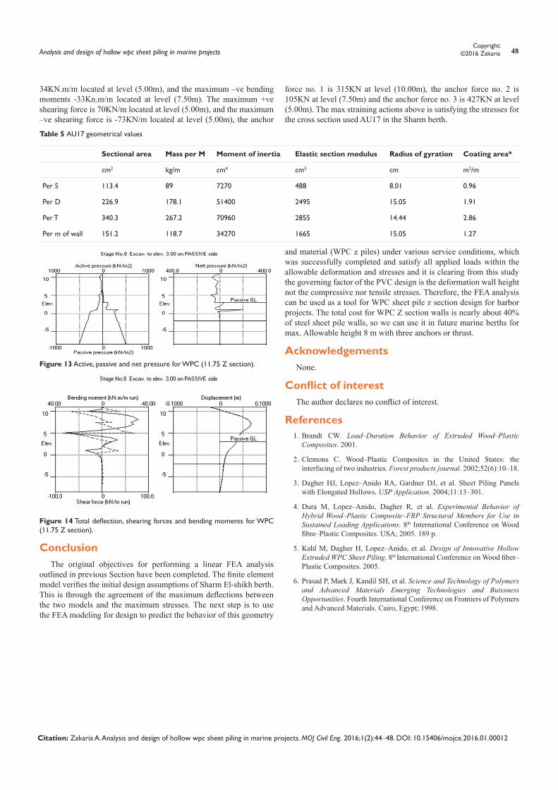
Deflection, Shearing forces and Bending Moments
The overall maximum deflection predicted by WALLAP for WPC 11.75 Z section is 6.7cm in the y direction occurring at a position (7.00m) from the origin as shown in Figure 13. And this value is allowed as the max allowable deflection is about 7cm. The shearing forces and bending moment’s predictions from the FEA model are presented in Figure 14. The maximum +ve bending moments are
Analysis and design of hollow wpc sheet piling in marine projects 48Copyright:
©2016 Zakaria
Citation: Zakaria A. Analysis and design of hollow wpc sheet piling in marine projects. MOJ Civil Eng. 2016;1(2):44‒48. DOI: 10.15406/mojce.2016.01.00012
34KN.m/m located at level (5.00m), and the maximum –ve bending moments -33Kn.m/m located at level (7.50m). The maximum +ve shearing force is 70KN/m located at level (5.00m), and the maximum –ve shearing force is -73KN/m located at level (5.00m), the anchor
force no. 1 is 315KN at level (10.00m), the anchor force no. 2 is 105KN at level (7.50m) and the anchor force no. 3 is 427KN at level (5.00m). The max straining actions above is satisfying the stresses for the cross section used AU17 in the Sharm berth.
Table 5 AU17 geometrical values
Sectional area Mass per M Moment of inertia Elastic section modulus Radius of gyration Coating area*
cm2 kg/m cm4 cm3 cm m2/m
Per S 113.4 89 7270 488 8.01 0.96
Per D 226.9 178.1 51400 2495 15.05 1.91
Per T 340.3 267.2 70960 2855 14.44 2.86
Per m of wall 151.2 118.7 34270 1665 15.05 1.27
Figure 13 Active, passive and net pressure for WPC (11.75 Z section).
Figure 14 Total deflection, shearing forces and bending moments for WPC (11.75 Z section).
ConclusionThe original objectives for performing a linear FEA analysis
outlined in previous Section have been completed. The finite element model verifies the initial design assumptions of Sharm El-shikh berth. This is through the agreement of the maximum deflections between the two models and the maximum stresses. The next step is to use the FEA modeling for design to predict the behavior of this geometry
and material (WPC z piles) under various service conditions, which was successfully completed and satisfy all applied loads within the allowable deformation and stresses and it is clearing from this study the governing factor of the PVC design is the deformation wall height not the compressive nor tensile stresses. Therefore, the FEA analysis can be used as a tool for WPC sheet pile z section design for harbor projects. The total cost for WPC Z section walls is nearly about 40% of steel sheet pile walls, so we can use it in future marine berths for max. Allowable height 8 m with three anchors or thrust.
AcknowledgementsNone.
Conflict of interestThe author declares no conflict of interest.
References1. Brandt CW. Load–Duration Behavior of Extruded Wood–Plastic
Composites. 2001.
2. Clemons C. Wood–Plastic Composites in the United States: the interfacing of two industries. Forest products journal. 2002;52(6):10–18.
3. Dagher HJ, Lopez–Anido RA, Gardner DJ, et al. Sheet Piling Panels with Elongated Hollows. USP Application. 2004;11:13–301.
4. Dura M, Lopez–Anido, Dagher R, et al. Experimental Behavior of Hybrid Wood–Plastic Composite–FRP Structural Members for Use in Sustained Loading Applications. 8th International Conference on Wood fibre–Plastic Composites. USA; 2005. 189 p.
5. Kahl M, Dagher H, Lopez–Anido, et al. Design of Innovative Hollow Extruded WPC Sheet Piling. 8th International Conference on Wood fiber–Plastic Composites. 2005.
6. Prasad P, Mark J, Kandil SH, et al. Science and Technology of Polymers and Advanced Materials Emerging Technologies and Buissness Opportunities. Fourth International Conference on Frontiers of Polymers and Advanced Materials. Cairo, Egypt; 1998.