Embed Size (px)
Citation preview
Analogue Signal Transmitter AST 3
Technical Manual
GB

Analogue Signal Transmitter AST 3
Contents 1. Introduction Versions ........................................ 1-1
Functions ...................................... 1-2
Technical data ............................... 1-4
2. Installation General ......................................... 2-1
Electrical installation ..................... 2-1
Presentation panel, AST 3P .......... 2-4
Operation indicator, AST 3B ......... 2-5
3. Set-up General ......................................... 3-1
Quick set-up .................................. 3-3
Normal set-up ................................ 3-7
Parameters .................................... 3-9
4. Calibration General ......................................... 4-1
Common calibration param. .......... 4-2
Data sheet calibration ................... 4-3
Dead weight calibration ................. 4-4
Table calibration ............................ 4-4
5. Operation General .......................................... 5-1
Power supply ................................. 5-1
Power-up sequence ....................... 5-1
Display views in Oper. mode ......... 5-2
Zero setting .................................... 5-3
Analogue output ............................. 5-3
Level supervision, relays ............... 5-4
6. Communication Communication interface ............... 6-1
Line termination ............................. 6-1
Transmission principles .................. 6-1
Modbus .......................................... 6-2
Register descr. -Process param. ... 6-6
I/O bit (coil) description ................ 6-11
Exception responses ................... 6-12
Set-up registers ........................... 6-13
External display ........................... 6-14
7. Troubleshooting General .......................................... 7-1
Error codes .................................... 7-1
Temporary comm. for AST 3B ....... 7-6
Appendices Set-up list for AST 3 .................. App. 1
Declaration of Conformity ......... App. 2

Technical Manual
Analogue Signal Transmitter AST 3
1-1
1. Introduction
AST 3 is a high performance signal transmitter, designed for industrial measuring by means of strain gauge transducers. The compact module is easily installed on a DIN-rail or a flat surface. By serial communication a number of AST 3 modules can be combined to form a network with a common control unit.
Transducer excitation is included in the transmitter module and the analogue transducer signal is converted to a digital signal with very high resolution. By parameter controlled calculations an internal measurement value is produced, which can be converted to a current or voltage signal at the analogue output. The measurement value can also be transmitted to the control unit, or to an external display unit. Level supervision at two levels can be performed and the status is transmitted over the serial communication.
All AST 3 inputs and outputs are galvanically isolated from each other and from the power supply for the unit.
Versions AST 3 is available in two versions, both including the same measuring functions and an analogue output:
AST 3B is designed for remote use. An external control unit is needed for set-up of parameter values, and it can also be used for presentation of the measurement value. In AST 3B a green LED is visible through a hole in the panel, indicating the operating state of the unit.
In AST 3P components are added to make also local use possible. A front panel with command keys and a display window allows local parameter set-up and display of both parameter and measurement values at the transmitter module. For AST 3P operating or error conditions are shown at the display window (the internal LED is not visible). AST 3P also includes two output relays for indication or control duties.
Technical Manual
1-2
Functions
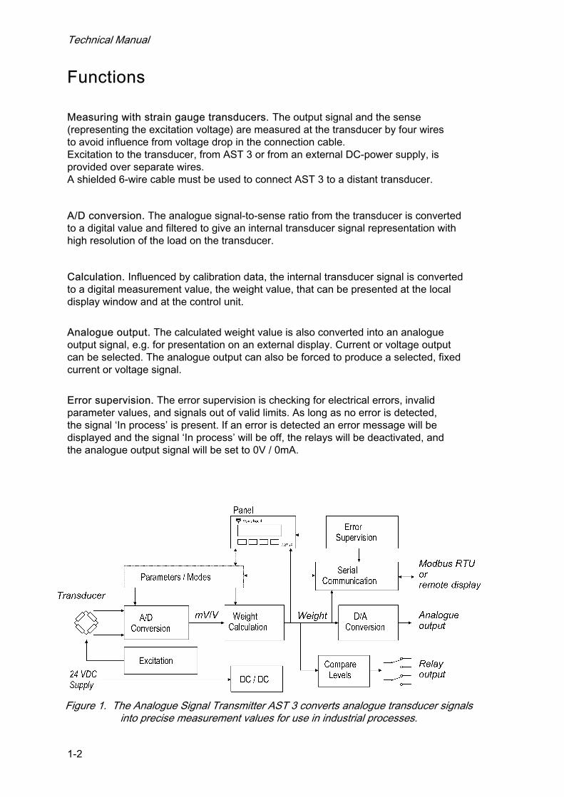
Measuring with strain gauge transducers. The output signal and the sense (representing the excitation voltage) are measured at the transducer by four wires to avoid influence from voltage drop in the connection cable. Excitation to the transducer, from AST 3 or from an external DC-power supply, is provided over separate wires. A shielded 6-wire cable must be used to connect AST 3 to a distant transducer.
A/D conversion. The analogue signal-to-sense ratio from the transducer is converted to a digital value and filtered to give an internal transducer signal representation with high resolution of the load on the transducer.
Calculation. Influenced by calibration data, the internal transducer signal is converted to a digital measurement value, the weight value, that can be presented at the local display window and at the control unit.
Analogue output. The calculated weight value is also converted into an analogue output signal, e.g. for presentation on an external display. Current or voltage output can be selected. The analogue output can also be forced to produce a selected, fixed current or voltage signal.
Error supervision. The error supervision is checking for electrical errors, invalid parameter values, and signals out of valid limits. As long as no error is detected, the signal ‘In process’ is present. If an error is detected an error message will be displayed and the signal ‘In process’ will be off, the relays will be deactivated, and the analogue output signal will be set to 0V / 0mA.
Figure 1. The Analogue Signal Transmitter AST 3 converts analogue transducer signals into precise measurement values for use in industrial processes.

Analogue Signal Transmitter AST 3
1-3
Levels. Two level comparators in AST 3 can be set to switch at defined levels for selected signals, reporting the status of the signals to the control unit. In AST 3P two switching relays are included. They can be set to indicate the status of the level comparators or the status of the signal ‘In process’.
Serial communication. In AST 3 the serial interface RS-485, on 2-wires or 4-wires, is used for communication with the control unit. Set-up and calibration parameters, weight value, level status, error status etc. is transmitted via the Modbus protocol. If the serial interface is not used for control unit communication, it can be used to transmit the weight value to external digital equipment.
Instrument modes. At power-on the unit enters the Start-up mode, displaying its identity while internal tests are performed. Then it may enter the Wait for start mode (selected by a parameter), waiting for a start command from the operator. After completed start-up, the AST 3 unit is normally working in Operating mode, continuously presenting the weight value (or other selected information). If editing of set-up parameters should be performed, AST 3 must be switched over to Set-up mode. If an error is detected, AST 3 will automatically switch over to Error mode, displaying an error message.
As AST 3 is in Set-up mode or Error mode, normal instrument operation is disabled, the relays are deactivated, and the analogue output is set to zero.
Parameter setting. In AST 3 set-up parameters are used to control all operating functions. The parameter values can be entered as numerical values or selected from a list of alternatives. Setting of the parameter values can be performed from a control unit. For AST 3P, the front panel keys and display window can also be used for the parameter setting.
Presentation. AST 3 can present parameter values and measured or calculated signal values at a control unit, and for AST 3P at the panel display. The measurement value is also presented by the analogue output signal.
Control unit
AST 3B
AST 3P
PC AST 3PExternal displayRS-485 RS-485
Figure 2. The AST 3 versions can utilise serial communication to carry out different operational tasks.
Technical Manual
1-4
Technical data Transducer input Transducers Max 8, 350 ohms each. Total load >45 ohms. Excitation Depending on the number of transducers connected: 8.8 VDC ±5 % with 1 transd. 8.7 VDC ±5 % with 2 transd. 8.5 VDC ±5 % with 3 transd. 7.7 VDC ±5 % with 4 transd. 6.5 VDC ±5 % with 6 transd. 5.5 VDC ±5 % with 8 transd. Signal input ± 3.3 mV/V. Sense input 1.5 – 10 VDC. A/D conversion 23 bits (8 300 000 counts). Patented design.
Analogue output Bipolar voltage or current. Voltage 0–10 VDC or +/-10 VDC over >500 ohms. Current 0–20 mA, +/-20 mA, 4–20 mA, -12–20 mA in <500 ohms.
Filter 0.05 to 75 Hz, selectable bandwidth. Resolution 16 bits (65 000 counts).
Non-linearity <0.01 % of range. Zero drift <0.005 % of range/°C. Gain drift <0.003 % of actual value/°C.
Serial output Can be used for control unit communication (Modbus) or external display.
Interface RS-485, 2-wires or 4-wires. Baud rate Up to 115.2 kbaud. Data format Modbus RTU protocol for control unit communication. Filter 0.05 to 75 Hz, selectable bandwidth. Non-linearity <0.005 % of range. Zero drift <0.0002 % of 3.3 mV/V /°C. Gain drift <0.0015 % of actual value/°C.
30
73575
100
110
5
60
85
Mounting holes, 2 x 4 mm dia. The snap fastener for
DIN rail can be opened with a fine screw driver.
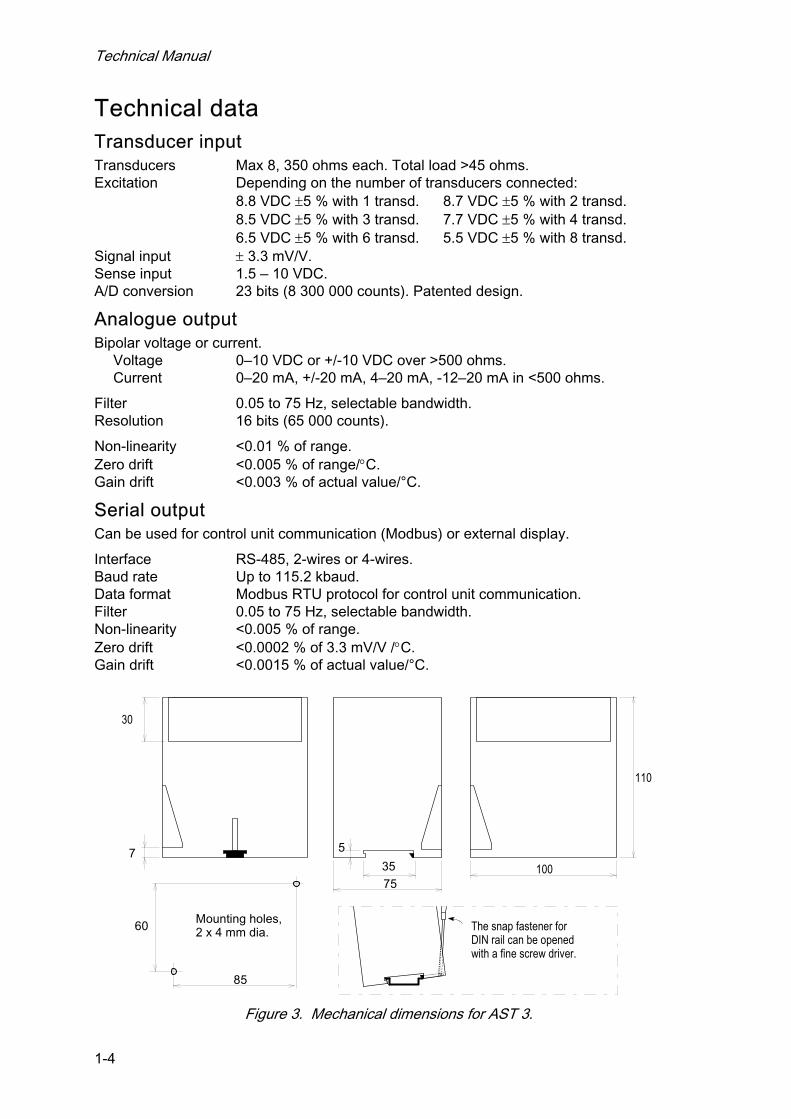
Figure 3. Mechanical dimensions for AST 3.
Analogue Signal Transmitter AST 3
1-5
Calibration Methods Data sheet, Dead weight or Table.
Power supply Supply voltage 24 VDC ±20 %. Consumption 7 W.
Environmental Temperature range –10 to +50 °C. CE conformity EMC, industrial for process control.
Mechanical data Dimensions 75 x 100 x 110 mm. At least 10 mm air gap between units. Rail mount DIN 46 277/3 and DIN EN 50022 (35 mm). Protection IP 20.
Relay output (for AST 3P only): Number of relays 2 (each with 1 switching group). Relay load Max 1 A, 30 V AC or DC.
Spark suppression required at inductive load.
Front panel (for AST 3P only): Display 2 x 16 character LCD display. Keys 4 keys for menu control and data entry.
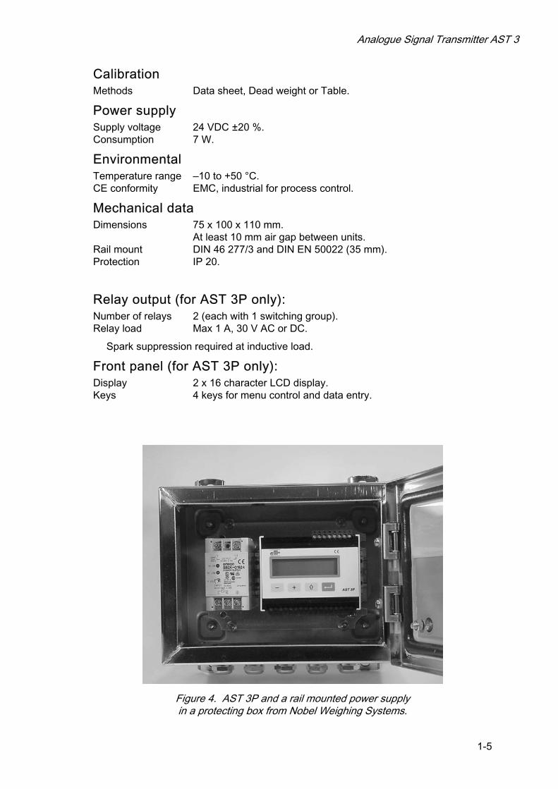
Figure 4. AST 3P and a rail mounted power supply in a protecting box from Nobel Weighing Systems.
Technical Manual
1-6
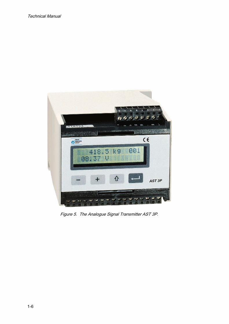
Figure 5. The Analogue Signal Transmitter AST 3P.

Analogue Signal Transmitter AST 3
2-1
2. Installation
General Each signal transmitter module AST 3 contains several circuit boards, built into a protective plastic housing. The module can be snap-mounted on a 35 mm wide DIN rail or attached on a flat surface by two 4 mm screws. Two groups of plug-in terminals for the cables are arranged on the module. The transducer cable is connected on one side of the module and all other cables on the opposite side.
Electrical installation All electrical connections to the AST 3 module, including possible connection to ground, are made via plug-in terminal blocks. Shielded cables are needed, except for the power supply, and the cables should be routed so that electro-magnetic interference from power cables is avoided. Input and output signals for AST 3 are galvanically isolated from each other to facilitate connection to various external equipment.
Cable connection is shown in the diagrams below.
Power supply Terminals 17, 18. The AST 3 unit is powered by 24 VDC, see requirements in Technical data. Nobel Weighing Systems provides rail mounted power supplies, intended for operation of AST 3 units.
Analogue output Terminals 24, 25. Current output or voltage output for presentation of the measured value at the process control or at an external analogue instrument. Connect the cable shield to ground, preferably to a ground terminal at the mounting rail.
17 +-18
+24 V DC0 V (24)
24V
+ OUT+OUT–
2425
Technical Manual
2-2
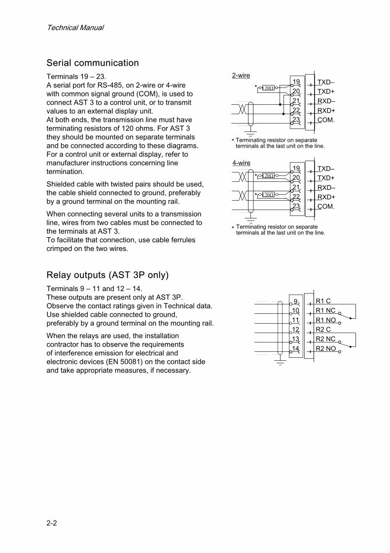
Serial communication Terminals 19 – 23. A serial port for RS-485, on 2-wire or 4-wire with common signal ground (COM), is used to connect AST 3 to a control unit, or to transmit values to an external display unit. At both ends, the transmission line must have terminating resistors of 120 ohms. For AST 3 they should be mounted on separate terminals and be connected according to these diagrams. For a control unit or external display, refer to manufacturer instructions concerning line termination.
Shielded cable with twisted pairs should be used, the cable shield connected to ground, preferably by a ground terminal on the mounting rail.
When connecting several units to a transmission line, wires from two cables must be connected to the terminals at AST 3. To facilitate that connection, use cable ferrules crimped on the two wires.
Relay outputs (AST 3P only) Terminals 9 – 11 and 12 – 14. These outputs are present only at AST 3P. Observe the contact ratings given in Technical data. Use shielded cable connected to ground, preferably by a ground terminal on the mounting rail.
When the relays are used, the installation contractor has to observe the requirements of interference emission for electrical and electronic devices (EN 50081) on the contact side and take appropriate measures, if necessary.
2-wire
* Terminating resistor on separate terminals at the last unit on the line.
120Ω1920212223
TXD–TXD+RXD–RXD+COM.
4-wire
Terminating resistor on separate terminals at the last unit on the line.
*
*
1920212223
TXD–TXD+
RXD–RXD+COM.
120Ω*
120Ω*
R1 C91011121314
R1 NCR1 NOR2 CR2 NCR2 NO
Analogue Signal Transmitter AST 3
2-3
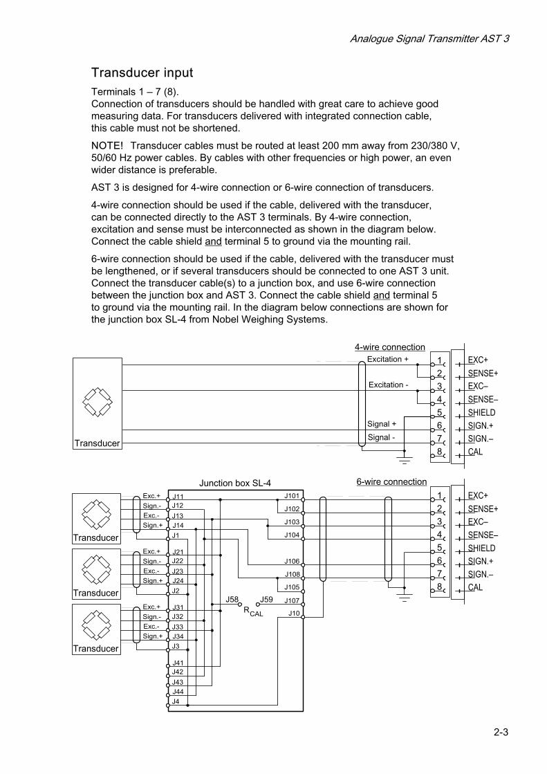
Transducer input Terminals 1 – 7 (8). Connection of transducers should be handled with great care to achieve good measuring data. For transducers delivered with integrated connection cable, this cable must not be shortened.
NOTE! Transducer cables must be routed at least 200 mm away from 230/380 V, 50/60 Hz power cables. By cables with other frequencies or high power, an even wider distance is preferable.
AST 3 is designed for 4-wire connection or 6-wire connection of transducers.
4-wire connection should be used if the cable, delivered with the transducer, can be connected directly to the AST 3 terminals. By 4-wire connection, excitation and sense must be interconnected as shown in the diagram below. Connect the cable shield and terminal 5 to ground via the mounting rail.
6-wire connection should be used if the cable, delivered with the transducer must be lengthened, or if several transducers should be connected to one AST 3 unit. Connect the transducer cable(s) to a junction box, and use 6-wire connection between the junction box and AST 3. Connect the cable shield and terminal 5 to ground via the mounting rail. In the diagram below connections are shown for the junction box SL-4 from Nobel Weighing Systems.
21
3
6
4
7
EXC+
SENSE+
SHIELDSIGN.+
Excitation +
Excitation -
Signal +
Signal -Transducer
Junction box SL-4
4-wire connection
6-wire connection
5
8 CAL
EXC–SENSE–
SIGN.–
Exc.+
Sign.-Exc.-Sign.+
Transducer
Transducer
Transducer
J11J12
J13J14
J1
J101
J102
J103
J104
J106
J108
J10
J105
J107J59J58
CALR
EXC+SENSE+
SHIELDSIGN.+
CAL
EXC–SENSE–
SIGN.–
Exc.+Sign.-Exc.-Sign.+
Exc.+Sign.-Exc.-Sign.+
J21J22
J23J24
J31J32
J33J34
J41J42
J43J44
J2
J3
J4
21
3
6
4
7
5
8
Technical Manual
2-4
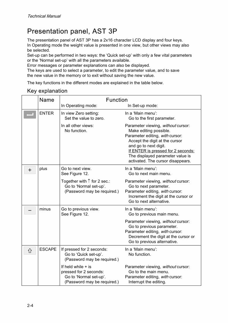
Presentation panel, AST 3P The presentation panel of AST 3P has a 2x16 character LCD display and four keys. In Operating mode the weight value is presented in one view, but other views may also be selected. Set-up can be performed in two ways: the ‘Quick set-up’ with only a few vital parameters or the ‘Normal set-up’ with all the parameters available. Error messages or parameter explanations can also be displayed. The keys are used to select a parameter, to edit the parameter value, and to save the new value in the memory or to exit without saving the new value.
The key functions in the different modes are explained in the table below.
Key explanation
Name Function In Operating mode: In Set-up mode:
ENTER In view Zero setting: In a ‘Main menu’:
Set the value to zero. Go to the first parameter.
In all other views: Parameter viewing, without cursor: No function. Make editing possible. Parameter editing, with cursor: Accept the digit at the cursor and go to next digit. If ENTER is pressed for 2 seconds: The displayed parameter value is activated. The cursor disappears.
plus Go to next view. In a ‘Main menu’:
See Figure 12. Go to next main menu.
Together with ↑ for 2 sec.: Parameter viewing, without cursor: Go to ‘Normal set-up’. Go to next parameter. (Password may be required.) Parameter editing, with cursor: Increment the digit at the cursor or Go to next alternative.
minus Go to previous view. In a ‘Main menu’:
See Figure 12. Go to previous main menu.
Parameter viewing, without cursor: Go to previous parameter. Parameter editing, with cursor: Decrement the digit at the cursor or Go to previous alternative.
ESCAPE If pressed for 2 seconds: In a ‘Main menu’:
Go to ‘Quick set-up’. No function. (Password may be required.)
If held while + is Parameter viewing, without cursor: pressed for 2 seconds: Go to the main menu. Go to ‘Normal set-up’. Parameter editing, with cursor: (Password may be required.) Interrupt the editing.

Analogue Signal Transmitter AST 3
2-5
Example for how to use the keys: As an AST 3P is started for the first time it enters the Operating mode, displaying the Weight value. This example describes how to change ‘Measurement unit’ to pounds (lb) and Capacity to 1000 (lb), using the ‘Quick set-up’. See figure 7.
* To leave Operating mode and enter ‘Quick set-up’, press for 2 seconds.
* ‘Main menu Quick set-up’ is displayed. Press to get to the first parameter in the ‘Quick set-up’.
* The first parameter, ‘Language’, is displayed. Press to get to ‘Measurement unit’.
* For parameter ‘Measurement unit’, the default value ‘kg’ is displayed.
Press to start editing. A cursor makes the first letter on the lower line blinking.
* With a cursor on the lower line or are used to step forwards or
backwards through the list of alternatives. Press or until ‘lb’ is displayed.
* To accept the displayed alternative, press for 2 seconds. The cursor disappears.
* Now, without cursor on the lower line, use to get to parameter ‘Capacity’. The default value on the lower line, 500.0 lb, should be changed to 1000.0 lb.
* Press to start editing. The lower line will display ‘00500.0 lb’ with a cursor at the first digit.
* The parameter value should be changed to ‘01000.0 lb’.
Press once to accept the first digit and move to the second digit.
Press or to change the digit to ‘1’.
Press to accept the value ‘1’ and move to next digit.
Press or to change the digit from ‘5’ to ‘0’. Now the value is correct.
Press for 2 seconds, the cursor disappears and ‘1000.0 lb’ is displayed.
* As the editing is ready, press to get to ‘Main menu Exit set-up’.
* Press . The sub menu ‘Save changes? No Esc. Yes’ will be displayed.
(Press if you do not wish to exit from the set-up mode.)
* Answer by (Yes) to save the new edited values.
Answer by (No) to cancel the new values and return to previously saved values.
In both cases the set-up is finished and the module switches to Operating mode, displaying the Weight value.
Operation indicator, AST 3B Instrument operation is always indicated by a green LED inside the module, and for AST 3B the LED is visible through a hole in the upper right corner of the front panel.
• At normal operation the LED is lit continuously. • As messages are transmitted on the serial communication, the LED is
lit with one short interruption per second during the transmission time. Transmission is indicated like this also in a module with error indication.
• If an error occurs and the operation is stopped, this is indicated by the LED giving only a short flash every two seconds.

Technical Manual
2-6
Analogue Signal Transmitter AST 3
3-1
3. Set-up
General All operating functions in AST 3 are controlled by permanently stored parameters, so the information will not be lost if the module is switched off. At delivery the parameters are factory-set to default values, giving the module an initial standard function. For AST 3 modules connected to a control system, the parameter values can be edited by Modbus communication from a control unit in the system. If a computer with Windows 95/98/ME/NT4.0/2000/XP is used, the deltaCOM program from Nobel Weighing Systems facilitates the editing of parameter values. For an AST 3P, all parameter values for the module can be edited by the front panel function keys.
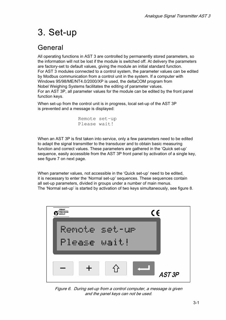
When set-up from the control unit is in progress, local set-up of the AST 3P is prevented and a message is displayed: Remote set-up Please wait!
When an AST 3P is first taken into service, only a few parameters need to be edited to adapt the signal transmitter to the transducer and to obtain basic measuring function and correct values. These parameters are gathered in the ‘Quick set-up’ sequence, easily accessible from the AST 3P front panel by activation of a single key, see figure 7 on next page.
When parameter values, not accessible in the ‘Quick set-up’ need to be edited, it is necessary to enter the ‘Normal set-up’ sequences. These sequences contain all set-up parameters, divided in groups under a number of main menus. The ‘Normal set-up’ is started by activation of two keys simultaneously, see figure 8.
Figure 6. During set-up from a control computer, a message is given and the panel keys can not be used.

Technical Manual
3-2
Conv. factor
Data sheet
Number of transd
Rated load
Rated output 1
Deadweight
Set zero
Calibration type Calibration type
9.80665
3
2000.0
2.03900 mV/V
Rated output 2
Rated output 3
Rated output 4
00054.50 kg
Value cal. p.10.0 kg
Value cal. p.2500.0 kg
2.03900 mV/V
2.03900 mV/V
2.03900 mV/V
Weight value 54.5 kg 001
R1:On R2:On
Start up/Reset
Quick set-up
Quick set-up
Language
Resolution
Measurement unit
Main menu
English
kg
0.1 kg
Capacity500.0 kg
Ana. output type4-20mA
Exit set-upMain menu
Save changes?No Esc. Yes
for 2 seconds
Operating mode
Set-up mode,
Transd.sign. p.10.00000 mV/V
Enter password:(Wrong)(Correct)
Shown only if 'Security lock' is On.
Shown only if any changes have been done.
Shown for the entered number of transducers.
Transd.sign. p.21.66631 mV/V
Set zero 00054.50 kg
Zero offset0.00 kg
Zero offset0.00 kg
Figure 7. In the ’Ouick set-up’ only some basic parameters can be edited.
Analogue Signal Transmitter AST 3
3-3
Quick set-up In ‘Quick set-up’ for AST 3P a few basic parameters can be edited. A separate publication, ”AST 3 Operating instructions, Quick installation”, gives a step-by step instruction for the set-up operation. A brief instruction is given below. Parameter explanations are found on pages 3-4, 3-5 or in the complete parameter list on pages 3-10 to 3-22.
Enter ‘Quick set-up’ Note! In Set-up mode all normal measuring operations are stopped!
Press for 2 seconds. ‘Main menu Quick set-up’ will be displayed, possibly after entry of a correct password.
Show the parameters
When ‘Main menu Quick set-up’ is displayed, press to attain the sequence of parameters. Parameter name and the actual parameter value are displayed
together. Press the key or the key to step backwards or forwards in the parameter sequence, see figure 7.
Select a parameter to edit
Press as the parameter is displayed. A blinking cursor appears to the left on the second line, and numerical parameter values get leading zeros. The cursor indicates that editing can be performed.
Edit a parameter value For choice parameters the value is selected from a list of alternatives. As a cursor
is blinking on the lower line, press the (or ) key to find the correct alternative,
then press for 2 seconds to accept it, and the cursor disappears. For numerical parameters each digit is edited separately. The digit at the cursor
can be edited by the or key. The value of that digit is accepted by , and the cursor moves to next digit. Repeat this procedure until a correct value with leading zeros is displayed, then press
for 2 seconds to accept it, and the cursor disappears. If the accepted value is out of range an error message will start flashing. Any key can be pressed to remove the message, cancel the incorrect value, and make continued editing possible.
Press to cancel the editing in progress and remove the cursor.
Calibration Two calibration types are supported by ‘Quick set-up’: data sheet calibration and dead weight calibration. See section Calibration for more information about calibration types and parameters.
Exit ‘Quick set-up’
See figure 7. First press to get to ‘Main menu Exit set-up’, and then press . If nothing was edited, ‘Quick set-up’ is finished and view ‘Weight value’ is displayed. If any parameter has been edited, ‘Save changes? No Esc. Yes’ is displayed.
(Press if you do not wish to exit from the set-up mode.)
If (Yes) is pressed, all edited parameter values will be saved. The new values should also be recorded in a set-up list. See appendix 2.
If (No) is pressed, all edited parameter values will be cancelled. All parameters resume the values they had before ‘Quick set-up’ was started.
This finishes the ‘Quick set-up’ and the view ‘Weight value’ will be displayed.

Technical Manual
3-4
Parameters in ‘Quick set-up’ ‘Quick set-up’ for AST 3 includes parameters for setting of basic instrument properties and for calibration of the measuring equipment. For each parameter a short explanation and the range for the parameter value is given. The parameters are also explained on pages 3-10 to 3-22.
‘Language’ Defines the language, used for parameters and messages.
List of alternatives: Svenska, English, Deutsch, Français. Default value: English.
‘Measurement unit’ Selection of engineering unit for the measurement value.
List of alternatives: NONE, g, kg, t, lb, N, kN, oz, psi, kPa, MPa, bar, l, lbf, kgf, PLI, N/m, kN/m, Nm, daN. Default value: kg.
‘Resolution’ Selection of decimal point position and resolution format for the measurement value. All set-up parameters using the selected measurement unit will be written with the resolution selected here.
List of alternatives: 0.001, 0.002, 0.005, 0.01, 0.02, 0.05, 0.1, 0.2, 0.5, 1, 2, 5, 10, 20, 50. Default value: 0.1.
‘Capacity’ Nominal range of the analogue output, expressed in ‘Measurement unit’. An asterisk (*) on the upper line indicates that the range for the analogue output has been changed by parameters in ‘Normal set-up’.
Possible values: from 0.5 to 999999. Default value: 500.
‘Ana. output type’ For the analogue output, several signal types can be selected: bipolar or monopolar current, bipolar or monopolar voltage.
List of alternatives: +/-20mA, -12–20mA, 0–20mA, 4–20mA, +/-10V, 0–10V. Default value: 4–20mA.
‘Calibration type’ Data sheet calibration is recommended as a preliminary calibration. With simple means it gives fairly good accuracy, so the equipment can be tested. Settings from an earlier dead weight calibration are lost if data sheet calibration is selected. Dead weight calibration is the most accurate calibration type. Known weights are used as load on the equipment. See section Calibration for further information on calibration types.
List of alternatives: Data sheet, Deadweight, Table. Default value: Data sheet.
Analogue Signal Transmitter AST 3
3-5
’Conv. factor’ This parameter defines the conversion factor by which a value expressed in ‘measure-ment unit’, must be multiplied to be expressed in the transducer data sheet unit. Consequently the factor is 1 if measurement unit and data sheet unit are equal. Default value can be used if ‘measurement unit’ is ‘kg’ and data sheet unit is ‘Newton’. Possible values: from 0.01 to 99. Default value: 9.80665.
‘Number of transd’ This parameter defines the total number of transducers and fixed support points for the load. If the number of support points is over 4, set the parameter value to 1. Possible values: 1 to 4. Default value: 3.
‘Rated load’ This parameter defines the rated load for the transducer type, expressed in the unit of the transducer data sheet. NOTE! If for example the rated load is 5 kN, this parameter should be set to 5 000 (N).
If the number of support points is over 4, the value of this parameter should be: rated load multiplied by that number. Possible values: from 1 to 999999. Default value: 2000.00.
‘Rated output 1’ (2, 3, 4) These parameters define the rated output for transducers and fixed support points. For transducers the rated output, in mV/V, is given in the data sheet. For fixed support points the rated output should be set to 0.00000 (mV/V). If the number of support points is over 4, the parameter value should be: the sum of all rated output values, divided by the number of transducers. Possible values: from 0 to +9.99999. Default value: 2.03900.
‘Value cal. p.1’ (p.2) These parameters define the known load on the scale for the two calibration points. Calibration point 1 is the lower point, normally unloaded scale. Calibration point 2 is the higher point, at least 2/3 of the nominal capacity. Possible values: from -999999 to +999999. Default values: Value cal. p.1: 0 Value cal. p.2: 500
‘Transd.sign. p.1’ (p.2) These parameters give the transducer signals for the two calibration points. The values can not be edited. Make a note of them in the ‘Set-up list’ (Appendix 2) for possible use in a table set-up of a replacement instrument. Possible values: from -9.99999 to +9.99999. Default values: Transd.sign. p.1: 0.00000 mV/V Transd.sign. p.2: 1.66631 mV/V
‘Set zero’ Used in both calibration types for zeroing of the instrument.
The actual weight is displayed. Press , the weight value is set to zero.
Press for 2 sec., the zeroing is accepted.
‘Zero offset’ Displayed after zeroing for both calibration types. Make a note of the parameter value in the ‘Set-up list’ (Appendix 2) for possible use in set-up of a replacement instrument.

Technical Manual
3-6
Level superv.
Level 1 source
Level 2 source
Level 1 hyst.
Level 2 hyst.
Level 1 value
Level 2 value
Relay 1 source
Relay 2 source
General Analogue output Communication
Language
Password
Display contrast
Ana. output type
Ana. range low
Calibration Diagnostics
More views
Resolution
Conv. factor
Start mode
Number of transd
Rated load
Rated output 1
Set zero
Main menu Main menu Main Menu
Not in use
0.0 kg
Not in use
0.0 kg
English
Auto
4
Off
Measurement unitkg
****
4-20mA
0.0 kg
9.80665
3
2000.0
2.03900 mV/V
Rated output 2
Rated output 3
Rated output 4
00054.50 kg
Value cal. p.10.0 kg
Value cal. p.2500.0 kg
Transd.sign. p.10.00000 mV/V
Transd.sign. p.21.66631 mV/V
Zero offset
Value cal. p.10.0 kg
Value cal. p.2500.0 kg
Transd.sign. p.10.00000 mV/V
Transd.sign. p.21.66631 mV/V
Set zero
Zero offset
Serialport mode
Baudrate
Modbus auto
9600
1
Ext. disp.format6
Main menu Main menu Main menu
Enter password
Weight value
(Wrong) (Correct)
54.5 kg 001 0.18200mV/V 001R1:On R2:On
Zero setting
Zero
Analogue output signal Input signal
5.430 V
In process
In process
2.03900 mV/V
2.03900 mV/V
2.03900 mV/V
0.00 kg0.00 kg
00054.50 kg
L1 0 kg
Level settings
Ana. range high500.0 kg
Ana. low adjust0
Operating mode
Set-up mode
Calibration
Progr. A001A120S/N: 97-1001
Serial no., Progr.
L2 0 kg
0.0 kg
0.0 kg
Zero function
Off
Capacity
Mains frequency50 Hz
Dig. bandwidth10 Hz
0.1 kg
500.0 kg
Calibration typeData sheet
Zero offset0.00 kg
Exit set-up
Save changes?No Esc. Yes
Main menu
Status input 1
Status input 2
Off
Off
Test relay 1
Test relay 2
Off
Off
Test ana. outp.0 V
Deadweight TableData sheet
+ +
Security lockOff
+++ +R1:On R2:On
Instrum. address
Data format8-none-1
2 sec. 2 sec. 2 sec. 2 sec. 2 sec. 2 sec.
Ana. high adjust0
Fixed ana. outp.0.00 V
Ana. bandwidth10 Hz
Shown only if 'Security lock' is On.
Shown only if 'More views' is On.
Shown only if 'Zero function' is On.
*/
*/
* */
* */
*/ Shown only when Level 1 is in use.
* */ Shown only when Level 2 is in use.
Shown only if'Security lock' is On.
* */
*/
*/
*/
*/ Not shown by "Fixed" parameters.
* */ Shown only by "Fixed" parameters.
*/ Not shown by 'Modbus auto'.
* */ Not shown by 'External display'.
*/
*/
* */
* * */
* * */ Shown only by 'External display'.
Shown only if changes have been done.
Shown for the enterednumber of transducers.
54.5 kg 001 54.5 kg 001
Set zero 00054.50 kg
Figure 8. In ‘Normal set-up’ all adequate parameters are available for editing. Display of some parameters, indicated by intersected frames, depends
on the setting for other parameters. The number of views available in Operating mode also depends on parameter settings. In this figure the parameter values are only examples.
Analogue Signal Transmitter AST 3
3-7
Normal set-up At delivery, the AST 3 parameters have default values. During the set-up operation the parameters are set to appropriate values for the actual installation. These values are saved in the AST 3 memory, and should also be recorded manually, for example in a set-up list like the one in Appendix 2. Set-up can be performed locally by the keys and the display on the front panel of AST 3P. Set-up can also be performed from a connected control unit, preferably using the deltaCOM program from Nobel Weighing Systems.
Enter ‘Normal set-up’ When AST 3 is in Set-up mode, all normal measuring is stopped.
From any of the views in Operating mode, switch-over to ‘Normal set-up’ takes place
when the keys and are activated simultaneously for 2 seconds. (Possibly after entry of a correct password).
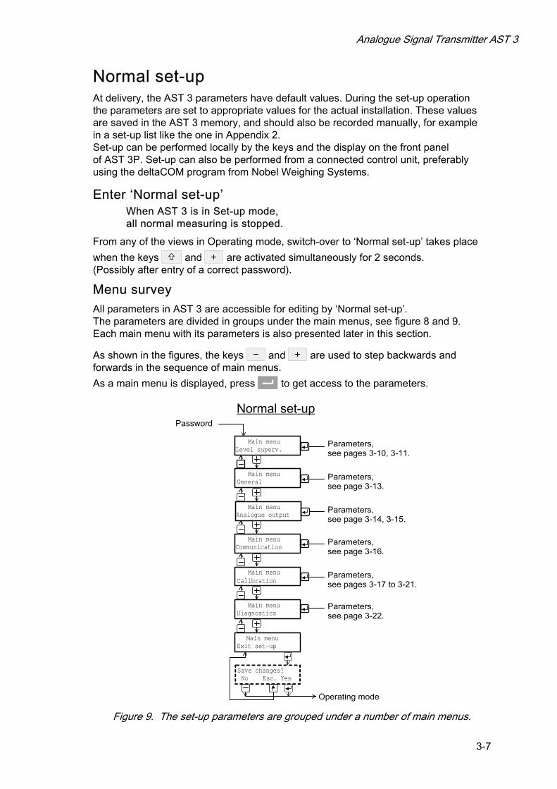
Menu survey All parameters in AST 3 are accessible for editing by ‘Normal set-up’. The parameters are divided in groups under the main menus, see figure 8 and 9. Each main menu with its parameters is also presented later in this section.
As shown in the figures, the keys and are used to step backwards and forwards in the sequence of main menus.
As a main menu is displayed, press to get access to the parameters.
Password
Normal set-up
Level superv.
General
Analogue output
Communication
Calibration
Main menu
Main menu
Main menu
Main menu
Main menu
Exit set-upMain menu
Parameters, see pages 3-10, 3-11.
Parameters, see page 3-13.
Parameters, see page 3-14, 3-15.
Parameters, see page 3-16.
Diagnostics
Main menu Parameters, see pages 3-17 to 3-21.
Save changes?No Esc. Yes
Parameters, see page 3-22.
Operating mode
Figure 9. The set-up parameters are grouped under a number of main menus.

Technical Manual
3-8
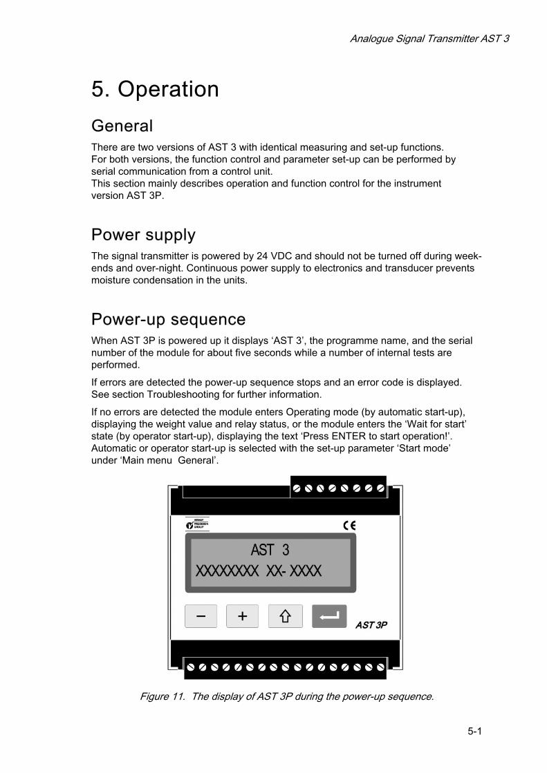
Main menus ‘Level superv.’ AST 3 has two identical channels for level supervision, called Level 1 and Level 2. Parameters under ‘Level superv.’ are used to activate these channels and to select supervision of the transducer input signal or of the internal weight value. Switching levels for the two channels are set individually to negative or positive values in a wide range. At the switching levels, a negative or positive hysteresis range can be added, giving a difference in switch level for increasing and decreasing signal. Status indication for Level 1 and Level 2 are sent on the serial communication. For AST 3P, two internal relays can be set to indicate the status of Level 1 and Level 2, or to indicate when AST 3P is in operation.
‘General’ This main menu contains parameters for general use, like setting of a security lock for entry in the set up mode, and a password for the lock, setting the type of instrument start up after power-on or reset, automatically or on operator command. Selection of the language, the number of available views, and the character contrast in the display window is also set by parameters under ‘General’.
‘Analogue output’ The analogue output can present the measurement value as current or voltage. Several formats can be selected here. Scaling and adjustment of the output can also be done. Parameters are included to set the analogue output to a fixed current or voltage level, independent of the internal weight value.
‘Communication’ The instrument has a serial port for communication purposes. By parameters it can be set for control unit communication with suitable baudrate, data format, and instrument address, or for transmission of the measurement value to an external display unit.
‘Calibration’ ‘Calibration’ contains parameters for selection of engineering unit and resolution for the measurement value, setting of capacity for the instrument, and setting of filters to reduce mains frequency interference and to give a suitable bandwidth for the internal signal conversion. Three calibration types are available: Data sheet, where information about the used transducers and values from the data sheets are entered. Dead weight, where the scale is loaded with known weights and the instrument is set to display corresponding weight values. Table, where recorded values from a previous dead weight calibration of the installation is entered in a replacement instrument. The calibration types also include parameters for zero setting and indication of the zero offset value.
‘Diagnostics’ Parameters are available to test the digital inputs, the internal relays, and the analogue output.
‘Exit set-up’ A sub menu gives the opportunity to save, or to cancel, all edited values before leaving the ‘Normal set-up’.

Analogue Signal Transmitter AST 3
3-9
Editing procedure, AST 3P To perform editing of a parameter in ’Normal set-up’, first go to the main menu that
contains the parameter and press ENTER (the key).
Then use key or to step forwards or backwards in the sequence to find the wanted parameter.
As the wanted set-up parameter is displayed, start the editing operation by . This will place a flashing cursor to the left on the lower line, and a numerical parameter value will get leading zeros. The cursor indicates that editing can be performed and that the panel key functions will be different. See also the table on page 2-4.
Key Function by parameter editing (with cursor)
Increment the cursor digit, or Go to next alternative.
Decrement the cursor digit, or Go to previous alternative.
(short) Accept the value of the cursor digit and go to next digit.
(2 sec.) Accept the actual parameter value and finish editing. If a value outside the range for a numeric parameter is entered, an error message is displayed. Then press any key to remove the message, cancel the value, and make continued editing possible.
Cancel the edited value, and interrupt the editing.
As the parameter editing is finished, the set-up mode must be closed to make normal operation possible.
To close the set-up mode,
press to get to the main menu,
press several times until ‘Main menu Exit set-up’ is displayed,
press , sub menu ‘Save changes? No Esc. Yes’ will be displayed.
(Press if you do not wish to exit from the set-up mode.)
Answer No ( ) All edited values are cancelled and the parameters will resume their previous values. AST 3P switches over to Operating mode, displaying the weight value.
Answer Yes ( ) All edited values are saved in the module memory. AST 3P switches over to Operating mode, displaying the weight value.
Parameters On the following pages all set-up parameters, in groups by the main menus they belong to, are presented in the order they appear in the set-up sequences. The first line indicates the parameter name and the Modbus addresses, used for set-up by serial communication. The parameters are saved in two different float formats and can therefore be read and written in two different registers. For choice parameters an index in [ ] is given for each alternative. (These indices are used by set-up via Modbus.)
For numerical parameters a value range is given.
At the end of the table, the default value is given in < >.
To the right there is a short parameter explanation and, in italic, the results for the different alternatives.
Technical Manual
3-10
[index] Range/Alternative Explanation and <default value> result of alternatives.
‘Main menu Level superv.’
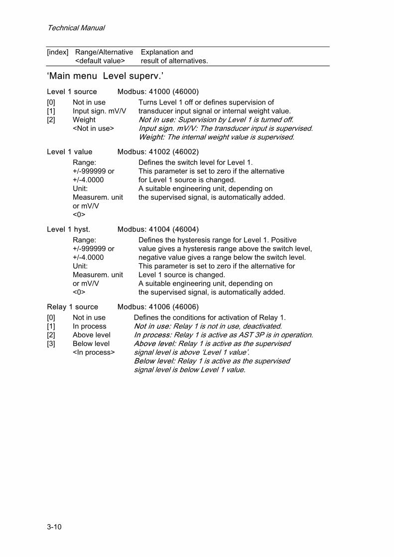
Level 1 source Modbus: 41000 (46000)
[0] [1] [2]
Not in use Input sign. mV/V Weight <Not in use>
Turns Level 1 off or defines supervision of transducer input signal or internal weight value. Not in use: Supervision by Level 1 is turned off. Input sign. mV/V: The transducer input is supervised. Weight: The internal weight value is supervised.
Level 1 value Modbus: 41002 (46002)
Range: +/-999999 or +/-4.0000 Unit: Measurem. unit or mV/V <0>
Defines the switch level for Level 1. This parameter is set to zero if the alternative for Level 1 source is changed. A suitable engineering unit, depending on the supervised signal, is automatically added.
Level 1 hyst. Modbus: 41004 (46004)
Range: +/-999999 or +/-4.0000 Unit: Measurem. unit or mV/V <0>
Defines the hysteresis range for Level 1. Positive value gives a hysteresis range above the switch level, negative value gives a range below the switch level. This parameter is set to zero if the alternative for Level 1 source is changed. A suitable engineering unit, depending on the supervised signal, is automatically added.
Relay 1 source Modbus: 41006 (46006)
[0] [1] [2] [3]
Not in use In process Above level Below level <In process>
Defines the conditions for activation of Relay 1. Not in use: Relay 1 is not in use, deactivated. In process: Relay 1 is active as AST 3P is in operation. Above level: Relay 1 is active as the supervised signal level is above ‘Level 1 value’. Below level: Relay 1 is active as the supervised signal level is below Level 1 value.
Analogue Signal Transmitter AST 3
3-11
[index] Range/Alternative Explanation and <default value> result of alternatives.
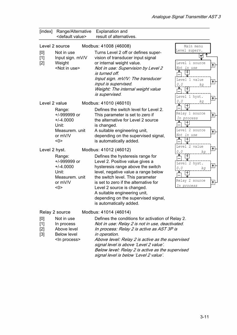
Level 2 source Modbus: 41008 (46008)
[0] [1] [2]
Not in use Input sign. mV/V Weight <Not in use>
Turns Level 2 off or defines super-vision of transducer input signal or internal weight value. Not in use: Supervision by Level 2 is turned off. Input sign. mV/V: The transducer input is supervised. Weight: The internal weight value is supervised.
Level 2 value Modbus: 41010 (46010)
Range: +/-999999 or +/-4.0000 Unit: Measurem. unit or mV/V <0>
Defines the switch level for Level 2. This parameter is set to zero if the alternative for Level 2 source is changed. A suitable engineering unit, depending on the supervised signal, is automatically added.
Level 2 hyst. Modbus: 41012 (46012)
Range: +/-999999 or +/-4.0000 Unit: Measurem. unit or mV/V <0>
Defines the hysteresis range for Level 2. Positive value gives a hysteresis range above the switch level, negative value a range below the switch level. This parameter is set to zero if the alternative for Level 2 source is changed. A suitable engineering unit, depending on the supervised signal, is automatically added.
Relay 2 source Modbus: 41014 (46014)
[0] [1] [2] [3]
Not in use In process Above level Below level <In process>
Defines the conditions for activation of Relay 2. Not in use: Relay 2 is not in use, deactivated. In process: Relay 2 is active as AST 3P is in operation. Above level: Relay 2 is active as the supervised signal level is above ‘Level 2 value’. Below level: Relay 2 is active as the supervised signal level is below ‘Level 2 value’.
Level superv.
Level 1 source
Level 2 source
Level 1 hyst.
Level 2 hyst.
Level 1 value
Level 2 value
Relay 1 source
Relay 2 source
Main menu
Not in use
0.0 kg
Not in use
0.0 kg
In process
In process
0.0 kg
0.0 kg

Technical Manual
3-12
Analogue Signal Transmitter AST 3
3-13
[index] Range/Alternative Explanation and <default value> result of alternatives.
‘Main menu General’
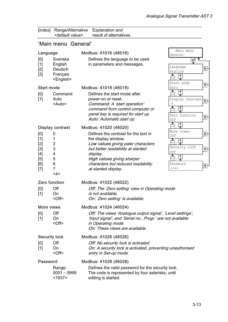
Language Modbus: 41016 (46016)
[0] [1] [2] [3]
Svenska English Deutsch Français <English>
Defines the language to be used in parameters and messages.
Start mode Modbus: 41018 (46018)
[0] [1]
Command Auto <Auto>
Defines the start mode after power-on or reset. Command: A ‘start operation’ command from control computer or panel key is required for start up. Auto: Automatic start up.
Display contrast Modbus: 41020 (46020)
[0] [1] [2] [3] [4] [5] [6] [7]
0 1 2 3 4 5 6 7 <4>
Defines the contrast for the text in the display window. Low values giving paler characters but better readability at slanted display. High values giving sharper characters but reduced readability at slanted display.
Zero function Modbus: 41022 (46022)
[0] [1]
Off On <Off>
Off: The ‘Zero setting’ view in Operating mode is not available. On: ‘Zero setting’ is available.
More views Modbus: 41024 (46024)
[0] [1]
Off On <Off>
Off: The views ‘Analogue output signal’, ‘Level settings’, ‘Input signal’, and ‘Serial no., Progr.’ are not available in Operating mode. On: These views are available.
Security lock Modbus: 41026 (46026)
[0] [1]
Off On <Off>
Off: No security lock is activated. On: A security lock is activated, preventing unauthorised entry in Set-up mode.
Password Modbus: 41028 (46028)
Range: 0001 – 9999 <1937>
Defines the valid password for the security lock. The code is represented by four asterisks, until editing is started.
General
Language
Password
Display contrast
More views
Start mode
Main menu
English
Auto
4
Off
****
Zero function
Off
Security lockOff

Technical Manual
3-14
[index] Range/Alternative Explanation and <default value> result of alternatives.
‘Main menu Analogue output’ Ana. output type Modbus: 41030 (46030)
[0] [1] [2] [3] [4] [5] [6] [7]
+/-20mA -12–20mA 0–20mA 4–20mA +/-10V 0–10V Fixed+/-20mA Fixed+/-10V <4–20mA>
Defines the type of signal, used to represent the weight value at the analogue output. +/-20mA, -12–20mA: bipolar current output, 0–20mA, 4–20mA: monopolar current output, +/-10V: bipolar voltage output, 0–10V: monopolar voltage output. An output signal, independent of the weight value can also be selected. Fixed+/-20mA: fixed current output, Fixed+/-10V: fixed voltage output.
Ana. range low Modbus: 41032 (46032)
Range: +/-999999 Unit: Measurem. unit <0>
Defines the weight value that should give the lowest value (0 mA, 4 mA or 0 V) at the analogue output. The value automatically changes to 0 if parameter ‘Capacity’ in ‘Quick set-up’ is edited. This parameter is not shown if a Fixed output type is selected in ‘Ana. output type’.
Ana. range high Modbus: 41034 (46034)
Range: +/-999999 Unit: Measurem. unit <500>
Defines the weight value that should give the highest analogue output. The value changes to the capacity value if parameter ‘Capacity’ in ‘Quick set-up’ is edited. This parameter is not shown if a Fixed output type is selected in ‘Ana. output type’.
Analogue Signal Transmitter AST 3
3-15
[index] Range/Alternative Explanation and <default value> result of alternatives.
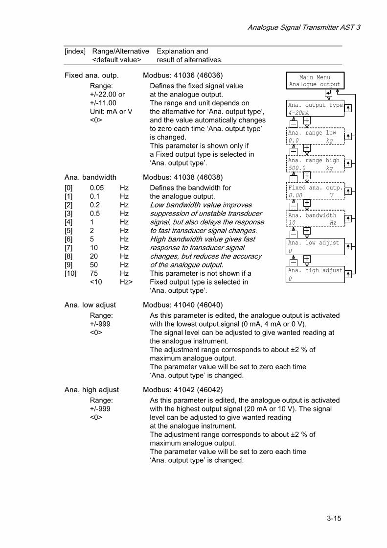
Fixed ana. outp. Modbus: 41036 (46036)
Range: +/-22.00 or +/-11.00 Unit: mA or V <0>
Defines the fixed signal value at the analogue output. The range and unit depends on the alternative for ‘Ana. output type’, and the value automatically changes to zero each time ‘Ana. output type’ is changed. This parameter is shown only if a Fixed output type is selected in ‘Ana. output type’.
Ana. bandwidth Modbus: 41038 (46038)
[0] [1] [2] [3] [4] [5] [6] [7] [8] [9] [10]
0.05 Hz 0.1 Hz 0.2 Hz 0.5 Hz 1 Hz 2 Hz 5 Hz 10 Hz 20 Hz 50 Hz 75 Hz <10 Hz>
Defines the bandwidth for the analogue output. Low bandwidth value improves suppression of unstable transducer signal, but also delays the response to fast transducer signal changes. High bandwidth value gives fast response to transducer signal changes, but reduces the accuracy of the analogue output. This parameter is not shown if a Fixed output type is selected in ‘Ana. output type’.
Ana. low adjust Modbus: 41040 (46040)
Range: +/-999 <0>
As this parameter is edited, the analogue output is activated with the lowest output signal (0 mA, 4 mA or 0 V). The signal level can be adjusted to give wanted reading at the analogue instrument. The adjustment range corresponds to about ±2 % of maximum analogue output. The parameter value will be set to zero each time ‘Ana. output type’ is changed.
Ana. high adjust Modbus: 41042 (46042)
Range: +/-999 <0>
As this parameter is edited, the analogue output is activated with the highest output signal (20 mA or 10 V). The signal level can be adjusted to give wanted reading at the analogue instrument. The adjustment range corresponds to about ±2 % of maximum analogue output. The parameter value will be set to zero each time ‘Ana. output type’ is changed.
Analogue output
Ana. output type
Ana. range low
Main Menu
4-20mA
0.0 kg
Ana. range high500.0 kg
Ana. low adjust0
Ana. high adjust0
Fixed ana. outp.0.00 V
Ana. bandwidth10 Hz

Technical Manual
3-16
[index] Range/Alternative Explanation and <default value> result of alternatives.
‘Main menu Communication’ Serialport mode Modbus: 41044 (46044)
[0] [1] [2] [3]
Not in use Modbus Modbus auto External display <Modbus auto>
Defines the serial port use. Not in use: The serial port is not used. Modbus: Communication with a control unit. Modbus auto: The control unit baudrate (from 9600) and bit configuration (8-none-1, 8-even-1 or 8-odd-1) is autodetected and used by AST 3. External display: The serial port is used for transmission of the measurement value to an external display unit.
Baudrate Modbus: 41046 (46046)
[0] [1] [2] [3] [4] [5] [6] [7] [8] [9]
300 600 1200 2400 4800 9600 19200 38400 57600 115200 <9600>
Defines the baudrate for the serial communication. The parameter must be set to the baudrate of the control computer, or to a baudrate suitable for the external display unit. This menu is not shown if ‘Modbus auto’ is selected in Serialport mode.
Data format Modbus: 41048 (46048)
[0] [1] [2] [3] [4] [5] [6] [7] [8]
7-none-2 7-even-1 7-even-2 7-odd-1 7-odd-2 8-none-1 8-none-2 8-even-1 8-odd-1 <8-none-1>
Defines the bit configuration for the serial communication. This parameter must be set to the same configuration as for the control computer, or to a configuration suitable for the external display unit. This menu is not shown if ‘Modbus auto’ is selected in Serialport mode.
Instrum. address Modbus: 41050 (46050)
Range: 1 to 247 <1>
Defines the address for the AST 3-unit. Shown only if ‘Modbus’ or ‘Modbus auto’ is selected in Serialport mode.
Ext. disp.format Modbus: 41052 (46052)
[0] [1] [2] [3] [4]
4 5 6 7 32 <6 >
Defines the number of digits on the external display unit. See section 6, Communication, for further information. Shown only if ‘External display’ is selected in Serialport mode.
Communication
Serialport mode
Baudrate
Modbus auto
9600
Instrum. address1
Ext. disp.format6
Main menu
Data format8-none-1
Analogue Signal Transmitter AST 3
3-17
[index] Range/Alternative Explanation and <default value> result of alternatives.
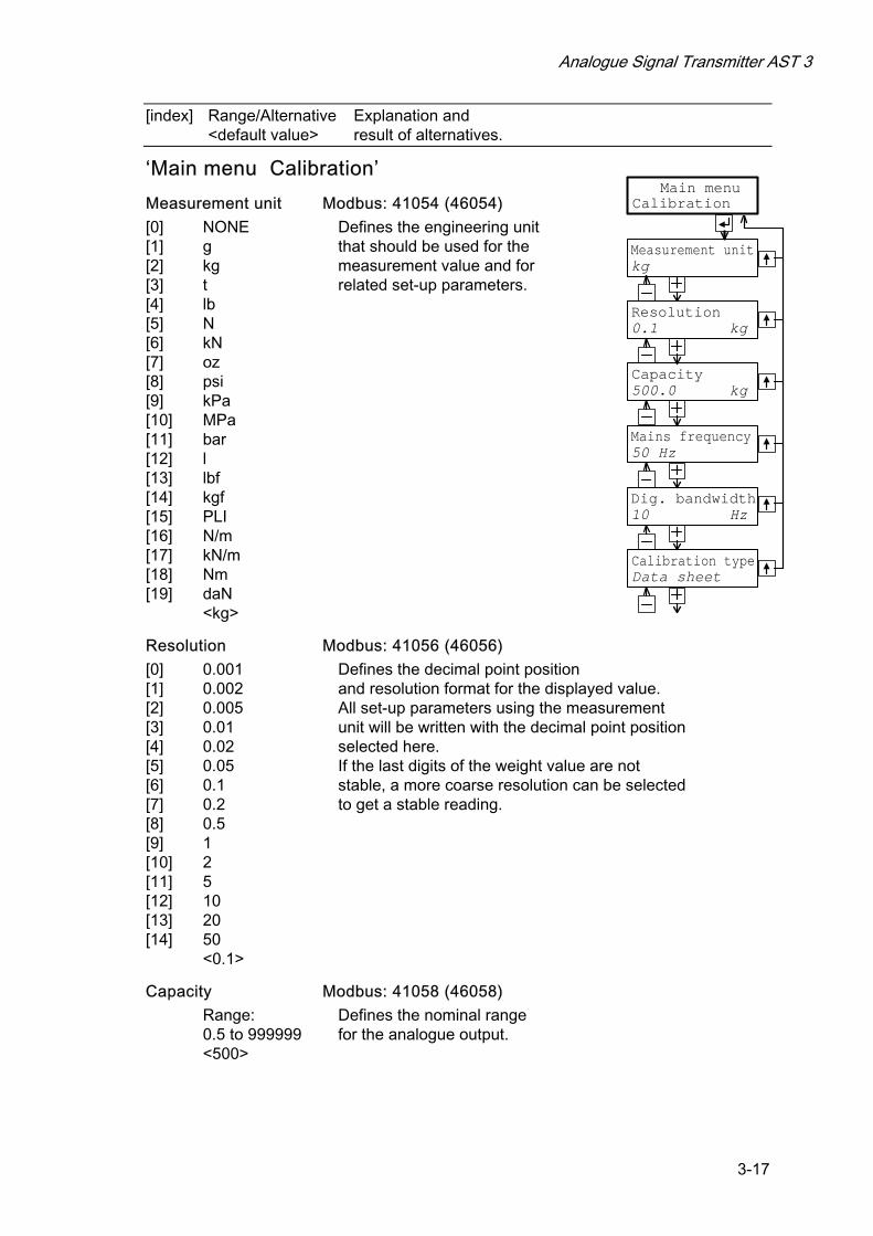
‘Main menu Calibration’
Measurement unit Modbus: 41054 (46054)
[0] [1] [2] [3] [4] [5] [6] [7] [8] [9] [10] [11] [12] [13] [14] [15] [16] [17] [18] [19]
NONE g kg t lb N kN oz psi kPa MPa bar l lbf kgf PLI N/m kN/m Nm daN <kg>
Defines the engineering unit that should be used for the measurement value and for related set-up parameters.
Resolution Modbus: 41056 (46056)
[0] [1] [2] [3] [4] [5] [6] [7] [8] [9] [10] [11] [12] [13] [14]
0.001 0.002 0.005 0.01 0.02 0.05 0.1 0.2 0.5 1 2 5 10 20 50 <0.1>
Defines the decimal point position and resolution format for the displayed value. All set-up parameters using the measurement unit will be written with the decimal point position selected here. If the last digits of the weight value are not stable, a more coarse resolution can be selected to get a stable reading.
Capacity Modbus: 41058 (46058)
Range: 0.5 to 999999 <500>
Defines the nominal range for the analogue output.
Calibration
Measurement unit
Dig. bandwidth
Capacity
Mains frequency
Resolution
Main menu
kg
0.1 kg
10 Hz
Calibration typeData sheet
50 Hz
500.0 kg

Technical Manual
3-18
[index] Range/Alternative Explanation and <default value> result of alternatives.
Mains frequency Modbus: 41060 (46060)
[0] [1]
50 Hz 60 Hz <50 Hz>
Defines a filter for suppression of mains frequency noise. 50 Hz: 50 Hz filter activated. 60 Hz: 60 Hz filter activated.
Dig. bandwidth Modbus: 41062 (46062)
[0] [1] [2] [3] [4] [5] [6] [7] [8] [9] [10]
0.05 Hz 0.1 Hz 0.2 Hz 0.5 Hz 1 Hz 2 Hz 5 Hz 10 Hz 20 Hz 50 Hz 75 Hz <10 Hz>
Defines the bandwidth of a filter for the internal weight value that is displayed at the front panel and can be sent to a connected control unit. Low value: Improves suppression of unstable transducer signal, but delays the response to fast changes in the transducer signal. High value: Gives fast response to changes in the transducer signal, but a less accurate value.
Calibration type Modbus: 41064 (46064)
[0] [1] [2]
Data sheet Deadweight Table <Data sheet>
Defines the type of calibration to be performed. Data sheet: Data sheet calibration is easy to use and doesn’t demand any reference equipment, except data from the transducer data sheet. Deadweight: Dead weight calibration is normally the most accurate calibration type. It requires known weights to at least 2/3 of the wanted measuring range. Table: Table calibration is used to enter recorded values from a previous calibration of the measuring equipment to a replacement instrument.

Analogue Signal Transmitter AST 3
3-19
[index] Range/Alternative Explanation and <default value> result of alternatives.
‘Data sheet’ Conv. factor Modbus: 41066 (46066)
Range: 0.01 to 99 <9.80665>
Defines the relationship between a measurement value expressed in data sheet unit and expressed in the selected measurement unit.
Number of transd Modbus: 41068 (46068)
Range: 1 to 4 <3>
Defines the total number of transducers and fixed support points in the scale installation. All transducers must have equal rated load. If the total number is over 4: enter 1 here.
Rated load Modbus: 41070 (46070)
Range: 1 to 999999 Unit: Data sheet unit <2000.0>
Defines the rated load for one transducer, expressed in the unit of the transducer data sheet. NOTE! If, for example, the data sheet value is 5 kN, the parameter should be set to 5 000 (N). If the total number of transducers and fixed supports is over 4: multiply that number with the rated load for one transducer and enter the result here.
Rated output 1 Modbus: 41072 (46072)
Range: 0 – +9.99999 Unit: mV/V <2.03900>
Defines rated output for transducer 1, specified in the data sheet. If the total number of transducers and fixed supports is over 4: add up all rated output values, divide by the number of transducers, and enter the result here.
Rated output 2 Modbus: 41074 (46074)
Range: 0 – +9.99999 Unit: mV/V <2.03900>
Defines the rated output signal for transducer 2. The value is specified in the transducer data sheet.
Rated output 3 Modbus: 41076 (46076)
Range: 0 – +9.99999 Unit: mV/V <2.03900>
Defines the rated output signal for transducer 3. The value is specified in the transducer data sheet.
Rated output 4 Modbus: 41078 (46078)
Range: 0 – +9.99999 Unit: mV/V <2.03900>
Defines the rated output signal for transducer 4. The value is specified in the transducer data sheet.
Set zero Modbus: 41088 (46088) and Zero offset Modbus: 41090 (46090)
See under ‘Deadweight’ on page 3-20.
Conv. factor
Number of transd
Rated load
Rated output 1
Set zero
9.80665
3
2000.00
2.03900 mV/V
Rated output 2
Rated output 3
Rated output 4
00054.50 kg
Zero offset
2.03900 mV/V
2.03900 mV/V
2.03900 mV/V
0.00 kg
To 'Main menu Calibration'

Technical Manual
3-20
[index] Range/Alternative Explanation and <default value> result of alternatives.
‘Deadweight’
Value cal. p.1 Modbus: 41080 (46080)
Range: +/-999999 Unit: Measurem. unit <0>
The scale is calibrated at two points, normally unloaded and loaded to at least 2/3 of the wanted range. This parameter defines the load on the scale at the lower calibration point, normally 0.
Value cal. p.2 Modbus: 41082 (46082)
Range: +/-999999 Unit: Measurem. unit <500>
This parameter defines the load on the scale at the higher calibration point, at least 2/3 of the wanted range.
Transd.sign. p.1 Modbus: 41084 (46084)
Range: +/-9.99999 Unit: mV/V <0.00000>
This parameter indicates the transducer signal at the lower calibration point. The value can not be edited.
Transd.sign. p.2 Modbus: 41086 (46086)
Range: +/-9.99999 Unit: mV/V <1.66631>
This parameter indicates the transducer signal at the higher calibration point. The value can not be edited.
Set zero Modbus: 41088 (46088)
Range: +/-999999 Unit: Measurem. unit <‘Live’>
The actual weight value is displayed. Enter the wanted value for the actual load, usually '0', i.e. unloaded scale. NOTE ! This parameter should be used for zeroing of the instrument.
Zero offset Modbus: 41090 (46090)
Range: +/-999999 Unit: Measurem. unit <0>
This parameter indicates the offset value acquired by zeroing in ‘Set zero’. If this parameter is edited, the zeroing will be influenced.
Value cal. p.10.0 kg
Value cal. p.2500.0 kg
Transd.sign. p.10.00000 mV/V
Transd.sign. p.21.66631 mV/V
Zero offset0.00 kg
To 'Main menu Calibration'
Set zero 00054.50 kg
Analogue Signal Transmitter AST 3
3-21
[index] Range/Alternative Explanation and <default value> result of alternatives.
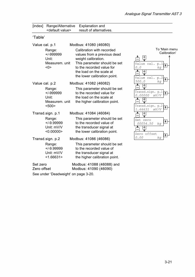
‘Table’
Value cal. p.1 Modbus: 41080 (46080)
Range: +/-999999 Unit: Measurem. unit <0>
Calibration with recorded values from a previous dead weight calibration. This parameter should be set to the recorded value for the load on the scale at the lower calibration point.
Value cal. p.2 Modbus: 41082 (46082)
Range: +/-999999 Unit: Measurem. unit <500>
This parameter should be set to the recorded value for the load on the scale at the higher calibration point.
Transd.sign. p.1 Modbus: 41084 (46084)
Range: +/-9.99999 Unit: mV/V <0.00000>
This parameter should be set to the recorded value of the transducer signal at the lower calibration point.
Transd.sign. p.2 Modbus: 41086 (46086)
Range: +/-9.99999 Unit: mV/V <1.66631>
This parameter should be set to the recorded value of the transducer signal at the higher calibration point.
Set zero Modbus: 41088 (46088) and Zero offset Modbus: 41090 (46090)
See under ‘Deadweight’ on page 3-20.
Value cal. p.10.0 kg
Value cal. p.2500.0 kg
Transd.sign. p.10.00000 mV/V
Transd.sign. p.21.66631 mV/V
Zero offset0.00 kg
To 'Main menu Calibration'
Set zero 00054.50 kg
Technical Manual
3-22
[index] Range/Alternative Explanation and <default value> result of alternatives.
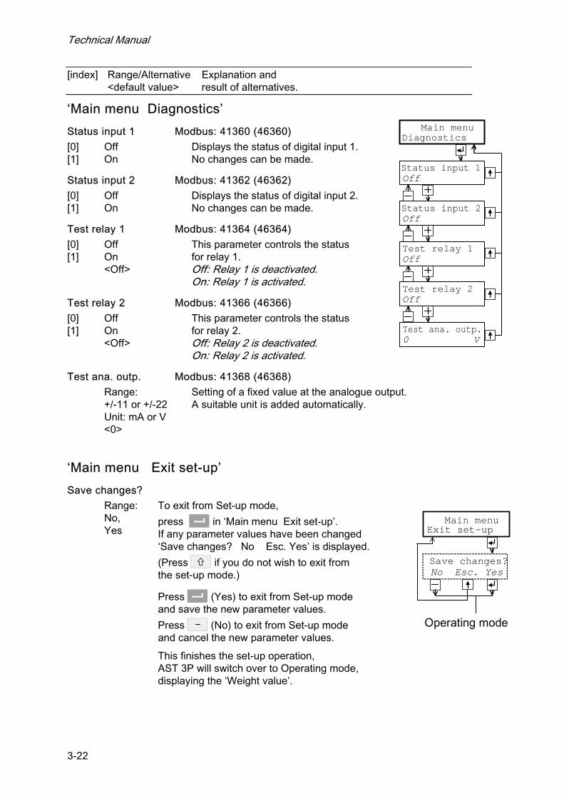
‘Main menu Diagnostics’
Status input 1 Modbus: 41360 (46360)
[0] [1]
Off On
Displays the status of digital input 1. No changes can be made.
Status input 2 Modbus: 41362 (46362)
[0] [1]
Off On
Displays the status of digital input 2. No changes can be made.
Test relay 1 Modbus: 41364 (46364)
[0] [1]
Off On <Off>
This parameter controls the status for relay 1. Off: Relay 1 is deactivated. On: Relay 1 is activated.
Test relay 2 Modbus: 41366 (46366)
[0] [1]
Off On <Off>
This parameter controls the status for relay 2. Off: Relay 2 is deactivated. On: Relay 2 is activated.
Test ana. outp. Modbus: 41368 (46368)
Range: +/-11 or +/-22 Unit: mA or V <0>
Setting of a fixed value at the analogue output. A suitable unit is added automatically.
‘Main menu Exit set-up’
Save changes?
Range: No, Yes
To exit from Set-up mode,
press in ‘Main menu Exit set-up’. If any parameter values have been changed ‘Save changes? No Esc. Yes’ is displayed.
(Press if you do not wish to exit from the set-up mode.)
Press (Yes) to exit from Set-up mode and save the new parameter values.
Press (No) to exit from Set-up mode and cancel the new parameter values.
This finishes the set-up operation, AST 3P will switch over to Operating mode, displaying the ‘Weight value’.
Diagnostics
Test relay 2
Status input 2
Test relay 1
Status input 1
Main menu
Off
Off
Off
Off
Test ana. outp.0 V
Main menu
Save changes?No Esc. Yes
Operating mode
Exit set-up
Analogue Signal Transmitter AST 3
4-1
4. Calibration
General When measuring with AST 3, the transducer output signal, corresponding to the transducer load, is converted to a weight value and presented at the analogue output, and at the AST 3P panel or at a connected control unit. The conversion is controlled by several parameter values, defined in the calibration.
Three calibration types are supported in AST 3:
• Data sheet calibration - entry of values from the transducer data sheet.
• Dead weight calibration - entry of values for certain known loads.
• Table calibration - entry of recorded values from a previous calibration.
It is recommended to start with a data sheet calibration, which is easy to accomplish and will give a fairly good accuracy. To get the best accuracy a dead weight calibration, with known loads to at least 2/3 of the measuring capacity, must be performed. After calibration the parameter values should be recorded. See appendix 1. If the transmitter module must be replaced, the recorded values can be used to make a table calibration for the new module.
All calibration parameters are collected under ‘Main menu Calibration’. See section 3 Set-up, Parameters and figure 8.
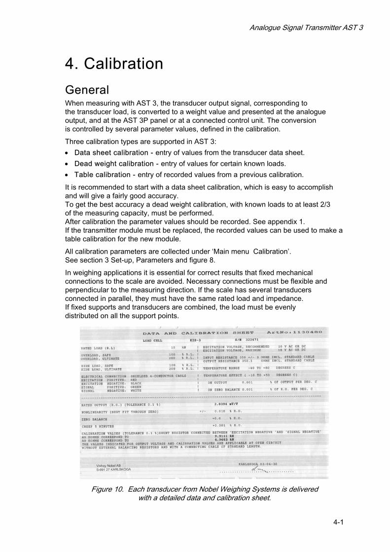
In weighing applications it is essential for correct results that fixed mechanical connections to the scale are avoided. Necessary connections must be flexible and perpendicular to the measuring direction. If the scale has several transducers connected in parallel, they must have the same rated load and impedance. If fixed supports and transducers are combined, the load must be evenly distributed on all the support points.
Figure 10. Each transducer from Nobel Weighing Systems is delivered with a detailed data and calibration sheet.
Technical Manual
4-2
Common calibration parameters For all the calibration types, measurement unit and resolution for the weight value and some other characteristics must be specified. The sequence of these parameters, common for all calibration types is given on pages 3-17 and 3-18.
The parameter ‘Measurement unit’ defines the engineering unit used for the weight value. This engineering unit will also be used for the Resolution and Capacity, for the Level values and for set-up of the analogue output.
The ‘Resolution’ parameter defines the number of decimals and the resolution for the weight value, displayed at AST 3P or transmitted to external equipment. If the weight value is oscillating, reduced resolution will give a more stable reading with reduced accuracy.
‘Capacity’ is a parameter, defining which weight value that will give full range signal at the analogue output. (The weight values corresponding to the highest and the lowest analogue output signals are also set by parameters under ‘Main menu Analogue output’.)
The parameter ‘Mains frequency’ controls filters for suppression of induced low frequency noise. It should be set to the surrounding mains frequency.
The parameter ‘Dig. bandwidth’ controls the filtering of the internal measurement signal. Low digital bandwidth gives a suppression of oscillations in the signal, making the reading more stable. High digital bandwidth makes it possible to detect fast changes in the measurement value.
In the following parameters under ‘Calibration’, calibration type and parameter values for the latest performed calibration are displayed.
If ‘Calibration type’ is not edited, the parameter values from previous calibration, including the zero offset value, will be displayed. If ‘Calibration type’ is edited, even if it is not changed, the zero offset value will be set to zero, so at least a new zeroing is required.
Editing of parameter values, including the type of calibration, should be performed according to instructions on page 3-9.
Example: Select a different type of calibration in ‘Calibration type’
1. As menu ‘Calibration type’ is displayed, press and a cursor will be flashing at the first character on the lower line.
2. Find the wanted calibration type, using the key or until the correct alternative is displayed.
3. Accept the displayed calibration type by pressing for 2 seconds. The cursor disappears and the selected calibration type will be displayed.
Analogue Signal Transmitter AST 3
4-3
Data sheet calibration Data sheet calibration is the default value for ‘Calibration type’ because it is recommended as first-time calibration for AST 3. An accuracy of 0.1 % can be obtained without use of known loads etc. By data sheet calibration in weighing applications it is essential that no external forces influence the scale installation. By data sheet calibration, values from the transducer data sheets should be entered as parameter values.
Conv. factor The transducer is often calibrated in an engineering unit which differs from the wanted unit of the displayed measurement value. This parameter defines a constant by which a weight value, expressed in the instrument measurement unit, should be multiplied to be expressed in the data sheet unit. When using a transducer, calibrated in Newton, in a scale displaying weight values in kg, the ‘Conv. factor’ should be the local gravitation constant in m/s2. The default value, 9.80665, is an international mean value for the gravitation constant (world-wide range 9.78 – 9.83). If the data sheet unit is the same as the measurement unit, the conversion factor parameter value should be set to 1.0000.
Number of transd In weighing applications the load on the scale may be supported by several transducers and fixed supports. This parameter value defines the total number, up to four, of transducers and fixed support points. If the scale has more than four support points this parameter should be set to ‘1’ and the parameter value for ‘Rated load’ and ‘Rated output 1’ should be calculated.
Rated load Rated load for the used transducer type, expressed in the data sheet unit used to calculate the conversion factor, should be entered as parameter value. NOTE! If the data sheet value is 5 kN, this parameter should be set to 5 000 (N). If several transducers are used in a scale, they must all have the same rated load. If the scale has more than four support points, ‘Number of transd’ should be set to ‘1’ and the value of this parameter should be calculated as: rated load for one transducer, multiplied by the total number of support points.
Rated output 1 Rated output is given in the data sheet for every transducer and should be entered here. Similar parameters follow for the number of support points indicated in ‘Number of transd’. For fixed supports, the rated output value is 0.00000 (mV/V).
If the scale has more than four support points, ‘Number of transd’ should be set to ‘1’ and the parameter value for ‘Rated output 1’ should be calculated as: the mean value of rated output for all active transducers.
Set zero After the data sheet values have been entered as parameter values, the instrument will perform necessary calculations, and a weight value corresponding to the actual load on the transducer will be displayed here.
The parameter value is set to zero as (enter) is pressed.
This zero value can be accepted, if is pressed for 2 seconds, or
edited (numerical value) and then accepted, if is pressed for 2 seconds.
Zero offset This parameter indicates the zero offset value that is used to get the ‘zero’ value selected for the parameter ‘Set zero’.

Technical Manual
4-4
Dead weight calibration This is normally the most accurate calibration type. The transducer signal is measured and stored together with the entered value of the known load (expressed in the selected measurement unit) for two calibration points. It is essential for good accuracy to utilise calibration points at both ends of the measuring range, for example at zero load and at least 2/3 of rated load. Make a manual record of all values, see appendix 1!
Value cal. p.1, Apply a well defined low load on the scale, normally 0 (zero), and enter the value of the load as parameter value. The entered load value and corresponding transducer signal value are saved in the instrument.
Value cal. p.2 Apply a well defined high load on the scale, at least 2/3 of the rated load, and enter the value of the load as parameter value. The entered load value and corresponding transducer signal value are saved in the instrument.
Transd.sign. p.1, This parameter indicates the stored transducer signal value for the low calibration point. The parameter value can not be edited.
Transd.sign. p.2 This parameter indicates the stored transducer signal value for the high calibration point. The parameter value can not be edited.
Set zero See Data sheet calibration on page 4-3.
Zero offset See Data sheet calibration on page 4-3.
Table calibration The table calibration can be used to copy values from a dead weight calibration for AST 3 to a replacement instrument. It is necessary to have access to recorded values from a dead weight calibration in two points. As Table calibration is selected, the ‘zero offset’ value is not set to zero.
Value cal. p.1, Value cal. p.2 These parameter values should be set to the recorded weight values from a previous calibration for the low calibration point (p.1) and the high calibration point (p.2).
Transd.sign. p.1, Transd.sign. p.2 These parameter values should be set to the recorded transducer signal values from a previous calibration for the corresponding calibration points.
Set zero See Data sheet calibration on page 4-3.
Zero offset See Data sheet calibration on page 4-3.
Analogue Signal Transmitter AST 3
5-1
5. Operation
General There are two versions of AST 3 with identical measuring and set-up functions. For both versions, the function control and parameter set-up can be performed by serial communication from a control unit. This section mainly describes operation and function control for the instrument version AST 3P.
Power supply The signal transmitter is powered by 24 VDC and should not be turned off during week-ends and over-night. Continuous power supply to electronics and transducer prevents moisture condensation in the units.
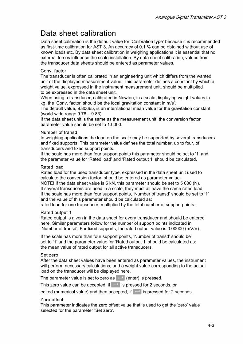
Power-up sequence When AST 3P is powered up it displays ‘AST 3’, the programme name, and the serial number of the module for about five seconds while a number of internal tests are performed.
If errors are detected the power-up sequence stops and an error code is displayed. See section Troubleshooting for further information.
If no errors are detected the module enters Operating mode (by automatic start-up), displaying the weight value and relay status, or the module enters the ‘Wait for start’ state (by operator start-up), displaying the text ‘Press ENTER to start operation!’. Automatic or operator start-up is selected with the set-up parameter ‘Start mode’ under ‘Main menu General’.
Figure 11. The display of AST 3P during the power-up sequence.

Technical Manual
5-2
Display views in Operating mode Figure 12. For AST 3P in Operating mode, at least one of the display views, Weight value, is always available. More views can be set On or Off in parameters under ‘Main menu General’.
The panel keys and are used to select among the available views.
In ‘Weight value’, and in some other views, information about serial communication is given at the end of the upper line: The module address means communication with a control unit. ‘EXT’ means communication to an external display unit. No indication in this area means that the serial communication is not in use.
Weight value This is the first view displayed after power-up, reset or set-up operations. The upper line displays the actual measurement value, here called weight value, followed by the area with information about the serial communication. The lower line displays the status for the used relays, R1:/R2: On or Off.
Zero setting This view can be set On or Off by parameter ‘Zero function’. Actual weight value, and information about the serial communication, is displayed. ‘Zero’ on the lower line
indicates that the weight value can be set to zero by ENTER (the key ).
NOTE! If AST 3P is unpowered or switched over to Set-up mode, the zero setting by this view will be lost and replaced by the zero setting from latest calibration.
Analogue output signal This view can be set On or Off by parameter ‘More views’. The upper line displays the actual weight value, followed by the area with information about the serial communication. The lower line displays the signal at the analogue output, a value in V or mA depending on the choice for parameter ‘Ana. output type’.
Weight valueR1:On R2:On
0.18200mV/V AdrInput signal
5.430 VAnalogue output signal
Progr. XXXXXXXXS/N: XX-XXXXS/N:, Progr.
L2 0 kgL1 999999 kgLevel settings
Enter password(Correct) (Wrong)
Set-up mode, 'Quick set-up'
Start up/Reset
Zero 54.5 kg AdrZero setting
54.5 kg Adr2 sec.
*/
*/ If and are activatedsimultaneously for 2 seconds,switch-over to Set-up mode,'Normal set-up' will take place
Always On
Set On/Off in Zero function
Set On/Off in Security lock
Set On/Off in More views
Set On/Off in More views
Set On/Off in More views (possibly after a correct password).
Set On/Off in More views
R1:On R2:On
54.5 kg Adr
2 sec.*/
2 sec.*/
2 sec.*/
2 sec.*/
2 sec.*/
Figure 12. The number of views available in Operating mode depends on several parameter settings.

Analogue Signal Transmitter AST 3
5-3
Level settings This display can be set On or Off by parameter ‘More views’. At the upper line the switching level for ‘Level 1’ is displayed. At the lower line the switching level for ‘Level 2’ is displayed.
Input signal This display can be set On or Off by parameter ‘More views’. The upper line displays the transducer input signal for the actual load, a value in mV/V, followed by the area with information about the serial communication. The lower line displays the states of the used relays, R1:/R2: On or Off.
S/N:, Progr. This display can be set On or Off by parameter ‘More views’. The upper line displays the serial number for the AST 3P module and the lower line displays the name of the installed programme.
From any of the above display views AST 3P can be switched over to Set-up mode.
‘Quick set-up’ is started if the key is pressed for 2 seconds. See figure 7.
‘Normal set-up’ is started if and are pressed for 2 seconds. See figure 8.
Zero setting Zero setting of the weight value is normally performed as the AST 3 unit is calibrated. By calibration the value of the zero offset parameter is permanently saved in the AST 3 memory and can only be changed in Set-up mode.
Temporary zero setting can be performed from the zero setting view in Operating mode, enabled by parameter ‘Zero function’ under ‘Main menu General’. NOTE! The zero offset value captured by this later method is lost if the AST 3 is unpowered or if Set-up mode is entered.
A third way of zero setting is via a serial communication command. NOTE! The zero offset value captured by this method is lost if the AST 3 is unpowered or if Set-up mode is entered.
Analogue output AST 3 has an analogue output with several voltage and current output ranges. The range limits are very precise, but minor adjustment can be done to adapt the output to the external equipment. A separate analogue output filter with a wide span of variable bandwidth can be set to reduce oscillation in the output signal, or to enable registration of fast changes by the analogue output. If an error occurs, the analogue output signal will be set to 0 V / 0 mA.
One way to select the range of measurement value, presented at the analogue output, is by parameter ‘Capacity’ in ‘Quick set-up’. Another way is to select any measurement value for the lowest and for the highest output signal respectively under ‘Main menu Analogue output’.
The analogue output can also be set to precise, fixed voltage or current output, independent of the internal weight value.
Technical Manual
5-4
Level supervision, relays Level supervision is used to indicate whether a selected signal is above or below a certain level. In AST 3 two level supervision channels are included. For each channel, supervised signal, switch level, and hysteresis region are set individually by parameters under ‘Main menu Level superv.’. To get fast response, the analogue or digital bandwidth, whichever is highest, is used for the supervision channels. The status of the level supervision channels (above or below Level) are available on the serial communication.
In AST 3P two output relays with switching contacts can be set to indicate either the status of the supervision channels, or if AST 3P is ‘In process’. If an instrument error occurs, both relays will be deactivated.
See page 3-10 and 3-11 for set-up sequence and parameters for the level supervision.
Level 1 source, Level 2 source Two signals can be selected for supervision in the two channels: Input sign. mV/V: Supervision of the input signal from the transducer. Weight : Supervision of the measurement value, named weight value, can be used to keep the load on a scale within given limits, to maintain a working pressure etc.
Level 1 value, Level 2 value The switching levels are set individually for the two level supervision channels within a wide range of positive and negative values. A suitable engineering unit is automatically added, depending on the selected level source.
Level 1 hyst., Level 2 hyst. Hysteresis is the difference between the switching level by increasing signal and by decreasing signal. The hysteresis can be set separately for the channels within a wide range of positive and negative values. A suitable engineering unit is automatically added, depending on the selected level source. The positive hysteresis region is from the Level value and upwards. The negative hysteresis region is from the Level value and downwards.
Relay 1 source, Relay 2 source Two relays in AST 3P can be controlled either by the level supervision channels or by the ‘In process’ signal. In process The relay is active as AST 3P is in Operating mode. Above level The relay is active as the value of the selected signal source is above the set switch level, hysteresis included. Below level The relay is active as the value of the selected signal source is below the set switch level, hysteresis included.
Level 1 value Level 2 value
Above Level 1
Level 2 hyst. negative
Level 1 hyst. positive
Increasing signal
Below Level 1
Above Level 2
Below Level 2
Figure 13. Influence of hysteresis on the indication from level supervision.
Level 1 having positive hysteresis and Level 2 having negative hysteresis.

Analogue Signal Transmitter AST 3
6-1
6. Communication The analogue signal transmitter AST 3 has one serial communications port, primarily used for communication with a control unit. Alternatively it can be used for data transmission to an external instrument.
Communication interface The serial communication utilises RS-485 for 2-wire or 4-wire. RS-485 is an interface working with differential voltages, giving a noise resistant transmission in a network with several units and long distances. The host computer (master) must have an asynchronous communication port for RS-485, or use a converter, e.g. Westermo MA-45 for RS-232 to RS-485 conversion. If 2-wire transmission is used, the control unit must be capable of data flow direction control or utilise a converter for automatic data flow direction control e.g. Westermo MA-45. When 4-wire transmission is used, no data flow direction control is needed.
Line termination To ensure good communication, the RS-485 transmission line requires correct termination at both ends. In the AST 3 unit, fail-safe resistors are always included, but at the last unit on the transmission line, terminating resistor(s) must be connected, see section Installation.
If the control unit is connected at one end of the transmission line, refer to the computer manual for line termination.
Transmission principles All the AST 3 units connected to the network can listen to what is transmitted in the network, but only one unit at a time can transmit. A time-sharing principle is needed to allow communication in both directions (half duplex).
All communication in the network must be initiated by the control unit (master). When AST 3 units are working together with a master, the AST 3 units are all slaves, only allowed to reply to master commands. As the master has sent a command message, addressed to a specific slave unit, it listens for the reply during a specified time, before sending next command message. If the reply from a slave unit fails it may be due to: - Mismatch in communication parameters. (baud rate, address, . . ) - More than one slave unit has been transmitting at the same time. This can distort the reply message and make it impossible to decode.
Technical Manual
6-2
Modbus General For communication between AST 3 and a master computer (PLC) the Modbus protocol is used. The Modbus protocol is a standard protocol, used for master/slave communication in the industry. With AST 3 the Modbus RTU protocol is used.
Information is transmitted in blocks of data to minimise polling and response time delays. For example both the error register, status register and weight register could be read with one command to the AST 3.
When a command that can not be performed is sent, the AST 3 responds with an exception code. For a better explanation of some errors, a special error register could be read.
Depending on the type of the communicating equipment (the master) in use, the commands in the application programme (PLC programme, or PC programme) may be different from type to type. However, if the master is not a Modicon PLC system, then the Modbus implementation in the master must have some cross-reference function to transfer the Modbus register and I/O bit numbering to the masters own register and I/O bit numbering. All register coils described in this manual uses the standard Modbus (Modicon) register and I/O numbering. See the masters own Modbus driver documentation for how the commands should be activated in the masters application programme.
For detailed information about the Modbus protocol see:
Modicon Modbus Protocol Reference Guide PI-MBUS-300 Rev.D.
Setup of Modbus communication
• Set parameter ‘Serialport mode’ (in ‘Main menu Communication’) to ‘Modbus auto’. The baudrate and bit settings will be autodetected.
• By default the AST 3 will be given the address 1. If more than one AST 3 is used in a network, each AST 3 must be given a unique address in parameter ‘Instrum. address’. (The address is shown to the right in the AST 3P display and when a correct message is received, it flashes.)
Note: By delivery an AST 3B (the instrument without display) is set to ‘Serialport mode’ = Modbus auto, and ‘Instrum. address’ = 1.
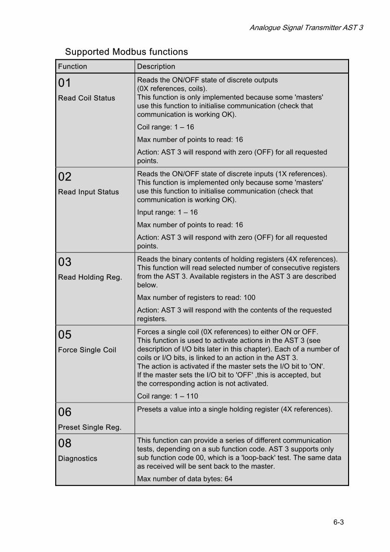
Analogue Signal Transmitter AST 3
6-3
Supported Modbus functions
Function Description
01 Read Coil Status
Reads the ON/OFF state of discrete outputs (0X references, coils). This function is only implemented because some 'masters' use this function to initialise communication (check that communication is working OK).
Coil range: 1 – 16
Max number of points to read: 16
Action: AST 3 will respond with zero (OFF) for all requested points.
02 Read Input Status
Reads the ON/OFF state of discrete inputs (1X references). This function is implemented only because some 'masters' use this function to initialise communication (check that communication is working OK).
Input range: 1 – 16
Max number of points to read: 16
Action: AST 3 will respond with zero (OFF) for all requested points.
03 Read Holding Reg.
Reads the binary contents of holding registers (4X references). This function will read selected number of consecutive registers from the AST 3. Available registers in the AST 3 are described below.
Max number of registers to read: 100
Action: AST 3 will respond with the contents of the requested registers.
05 Force Single Coil
Forces a single coil (0X references) to either ON or OFF. This function is used to activate actions in the AST 3 (see description of I/O bits later in this chapter). Each of a number of coils or I/O bits, is linked to an action in the AST 3. The action is activated if the master sets the I/O bit to 'ON'. If the master sets the I/O bit to 'OFF' ,this is accepted, but the corresponding action is not activated.
Coil range: 1 – 110
06 Preset Single Reg.
Presets a value into a single holding register (4X references).
08 Diagnostics
This function can provide a series of different communication tests, depending on a sub function code. AST 3 supports only sub function code 00, which is a 'loop-back' test. The same data as received will be sent back to the master.
Max number of data bytes: 64

Technical Manual
6-4
Function Description
15 Force Multiple Coils
Forces each coil (0X references) in a sequence of coils to either ON or OFF. This function is used to activate an action in the AST 3 (see description of I/O bits below). Each coil or I/O bit is linked to an action in the AST 3. The action is activated if the master sets the I/O bit to 'ON'. If the master sets the I/O bit to 'OFF' , this is accepted, but the corresponding action is not activated. NOTE! Even though it is possible to set multiple I/O bits (coils) with this function, AST 3 will act on the lowest addressed I/O bit (coil) only. Example: To set coil 8, the first coil to set must be number 8.
I/O bit (coil) number range: 0 – 110 Max. number of points: 16 (only the first is used)
16 Preset Multiple Reg.
Presets values into a sequence of holding registers (4X references). This function will preset values into the selected number of consecutive registers in the AST 3.
Max number of registers to preset: 100
Note: No broadcast messages are allowed.
NOTE! It is possible to send or fetch any number of registers (max 100) or I/O bits (max. 16). If the master tries to read more registers than there are available, the AST 3 module will send dummy values for those registers not available.
Data representation Data values (weight values and setpoint values) sent to and from the AST 3 uses 16 bit holding registers (40XXX).
All operative parameters: weight, status, etc. are stored in three different register areas in the AST 3. Which area that should be used depends on the master (PLC).
• Integer area: Two different types - 16 bit unsigned integer - 32 bit scaled integer
• Float area
• Modicon float area
Operative parameters Integer area Unsigned integer (1 modbus register)
Error codes, status etc. are saved in one modbus register as an unsigned integer (16 bit number without decimals).
Scaled integer (2 modbus registers + 1 modbus register = 3 modbus registers)
Values bigger than 32767 and values containing decimals (Weight, levels) are always saved in a special 3 register format. The first two registers are used as a 32 bit long integer value (with sign) and the third register is holding the number of decimals in the value.
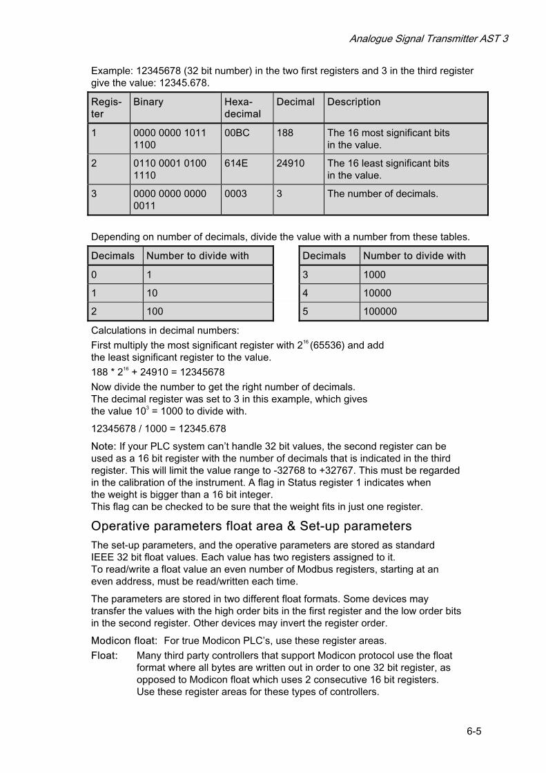
Analogue Signal Transmitter AST 3
6-5
Example: 12345678 (32 bit number) in the two first registers and 3 in the third register give the value: 12345.678.
Regis- ter
Binary Hexa-decimal
Decimal Description
1 0000 0000 1011 1100
00BC 188 The 16 most significant bits in the value.
2 0110 0001 0100 1110
614E 24910 The 16 least significant bits in the value.
3 0000 0000 0000 0011
0003 3 The number of decimals.
Depending on number of decimals, divide the value with a number from these tables.
Decimals Number to divide with Decimals Number to divide with
0 1 3 1000
1 10 4 10000
2 100 5 100000
Calculations in decimal numbers:
First multiply the most significant register with 216 (65536) and add the least significant register to the value.
188 * 216 + 24910 = 12345678
Now divide the number to get the right number of decimals. The decimal register was set to 3 in this example, which gives the value 103 = 1000 to divide with.
12345678 / 1000 = 12345.678
Note: If your PLC system can’t handle 32 bit values, the second register can be used as a 16 bit register with the number of decimals that is indicated in the third register. This will limit the value range to -32768 to +32767. This must be regarded in the calibration of the instrument. A flag in Status register 1 indicates when the weight is bigger than a 16 bit integer. This flag can be checked to be sure that the weight fits in just one register.
Operative parameters float area & Set-up parameters The set-up parameters, and the operative parameters are stored as standard IEEE 32 bit float values. Each value has two registers assigned to it. To read/write a float value an even number of Modbus registers, starting at an even address, must be read/written each time.
The parameters are stored in two different float formats. Some devices may transfer the values with the high order bits in the first register and the low order bits in the second register. Other devices may invert the register order.
Modicon float: For true Modicon PLC’s, use these register areas.
Float: Many third party controllers that support Modicon protocol use the float format where all bytes are written out in order to one 32 bit register, as opposed to Modicon float which uses 2 consecutive 16 bit registers. Use these register areas for these types of controllers.

Technical Manual
6-6
Register description - Process parameters AST 3 simulates a number of Modicon 'Holding Registers' (registers 4XXXX ... ). These are 16 bits binary registers and holds the data that can be transferred between the master and the AST 3. Some of these registers can only be read from the master, while others can both be read from and written to. The Modbus function 03 'Read Holding Registers' should be used to read these register and the Modbus function 05 'Preset Single Register' or 16 'Preset Multiple Registers' should be used to write to the registers. This table is a summary of all process parameters in the AST 3. The leftmost column holds the registers that should be used when float numbers can’t be read, and the next two columns hold the register numbers for parameters in float format.
A good way to find out which of the float formats that should be used is to read the ‘Instrument type’ register (40200/45200) which should equal 2001 for AST 3.
Register area Integer
Register area Float (2 reg./value)
Register area Modicon float (2 reg./value)
Explanation R/W
40001 (1 reg) 40200 45200 Instrument type R
40002 (1 reg) 40202 45202 Program number R
40003 (1 reg) 40204 45204 Program version R
40004 (3 reg) 40208 45208 Serial number R
40007 (1 reg) 40210 45210 Command error R
40008 (1 reg) 40212 45212 Instrument state R
40009 (1 reg) 40214 45214 Instrument error R
40010 (1 reg) 40216 45216 Status 1 R
40011 (1 reg) 40218 45218 Status 2 R
40012 (3 reg) 40220 45220 Weight R
40024 (3 reg) 40228 45228 Analogue output value R
40027 (3 reg) 40230 45230 Input signal (mV/V) R
40030 (1 reg) 40232 45232 Command register R/W *
40031 (3 reg) 40234 45234 Level 1 value R/W
40034 (3 reg) 40236 45236 Level 2 value R/W
40037 (3 reg) 40238 45238 Analogue fixed value R/W
Important: The weight register should never be read alone because the status of the value is indicated in some other registers. A good choice is to read at least the registers 40009 – 40014 (integer) or the registers 40214 – 40221 (45214 – 45221) (float).
*/ The read value is always ‘zero’.

Analogue Signal Transmitter AST 3
6-7
Instrument type register This is a READ ONLY register.
This register holds the type of the instrument. For AST 3 this value is 2001.
Program number This is a READ ONLY register.
This register holds the program number of the AST 3. Normal programs have a value below 100 and special programs a value above 100.
Program version This is a READ ONLY register.
This register holds the program version of the AST 3. The value 100 means 1.00.
Serial number This is a READ ONLY register.
This register holds the serial number of the instrument. The value 971000 means 97-1000. This can be used by the master to be sure that a instrument with a specific serial number is used for a special process.
Command error This is a READ ONLY register.
This register holds the error code when a command has been sent to the AST 3. A command that gives a 03 or 07 as exception will have an error code with a better description of the problem in this register. For an explanation of the error codes see chapter 7 Troubleshooting. Normally this register should contain ‘00’ which means no error. Error codes 100 to 65535 are valid in this register.
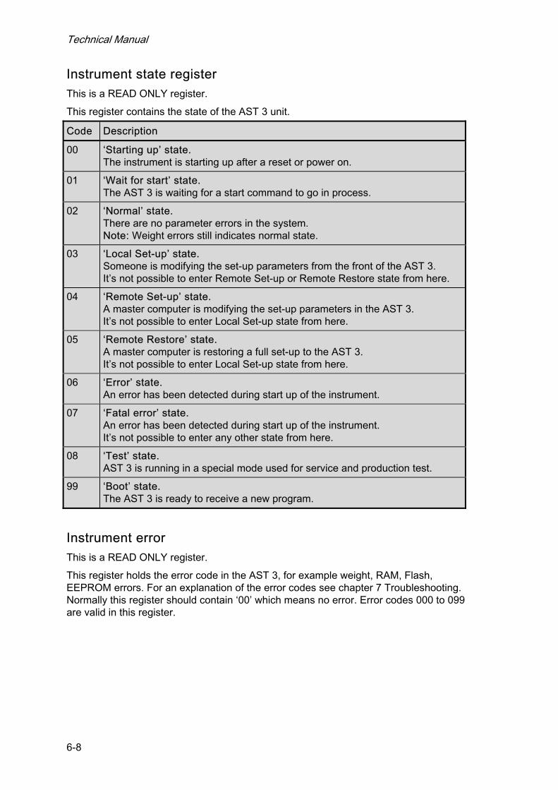
Technical Manual
6-8
Instrument state register This is a READ ONLY register.
This register contains the state of the AST 3 unit.
Code Description
00 ‘Starting up’ state. The instrument is starting up after a reset or power on.
01 ‘Wait for start’ state. The AST 3 is waiting for a start command to go in process.
02 ‘Normal’ state. There are no parameter errors in the system. Note: Weight errors still indicates normal state.
03 ‘Local Set-up’ state. Someone is modifying the set-up parameters from the front of the AST 3. It’s not possible to enter Remote Set-up or Remote Restore state from here.
04 ‘Remote Set-up’ state. A master computer is modifying the set-up parameters in the AST 3. It’s not possible to enter Local Set-up state from here.
05 ‘Remote Restore’ state. A master computer is restoring a full set-up to the AST 3. It’s not possible to enter Local Set-up state from here.
06 ‘Error’ state. An error has been detected during start up of the instrument.
07 ‘Fatal error’ state. An error has been detected during start up of the instrument. It’s not possible to enter any other state from here.
08 ‘Test’ state. AST 3 is running in a special mode used for service and production test.
99 ‘Boot’ state. The AST 3 is ready to receive a new program.
Instrument error This is a READ ONLY register.
This register holds the error code in the AST 3, for example weight, RAM, Flash, EEPROM errors. For an explanation of the error codes see chapter 7 Troubleshooting. Normally this register should contain ‘00’ which means no error. Error codes 000 to 099 are valid in this register.
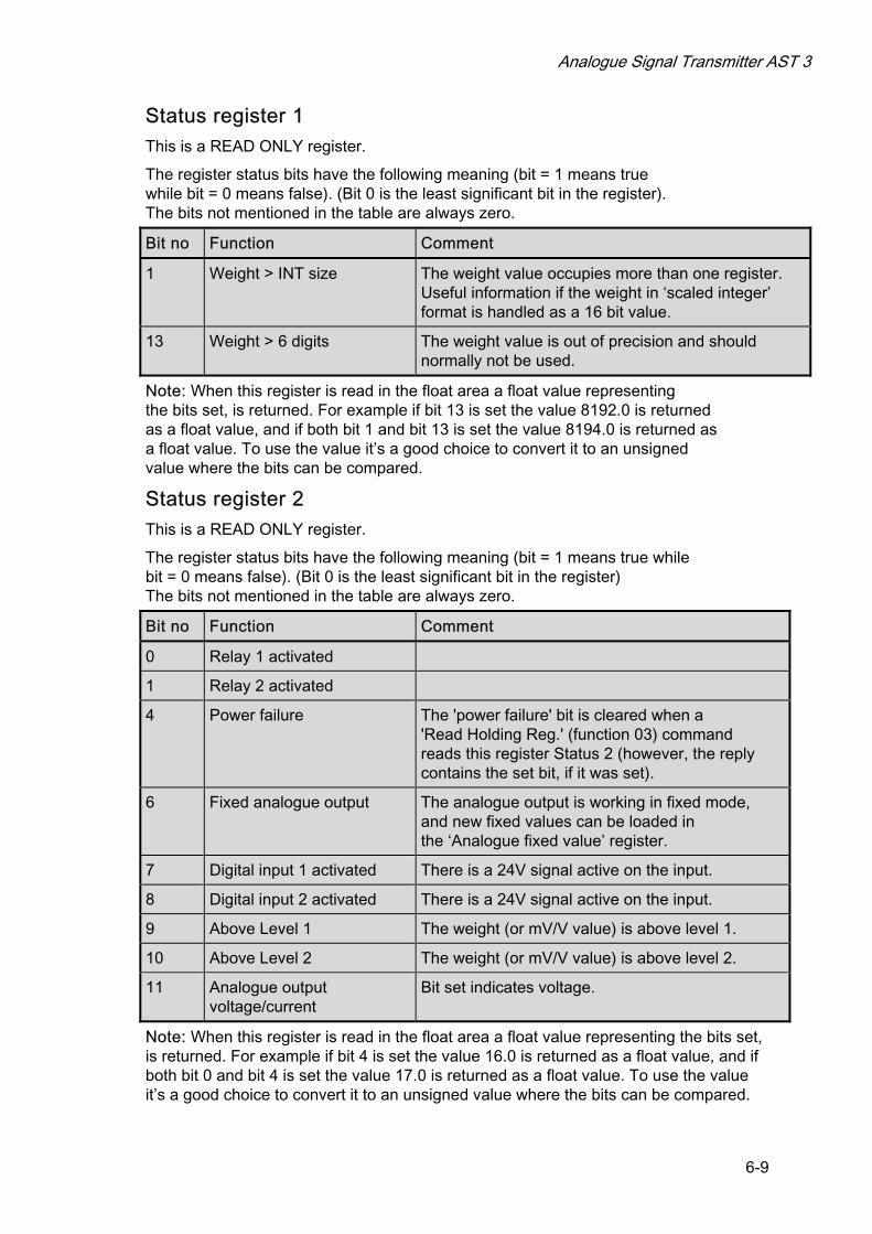
Analogue Signal Transmitter AST 3
6-9
Status register 1 This is a READ ONLY register.
The register status bits have the following meaning (bit = 1 means true while bit = 0 means false). (Bit 0 is the least significant bit in the register). The bits not mentioned in the table are always zero.
Bit no Function Comment
1 Weight > INT size The weight value occupies more than one register. Useful information if the weight in ‘scaled integer’ format is handled as a 16 bit value.
13 Weight > 6 digits The weight value is out of precision and should normally not be used.
Note: When this register is read in the float area a float value representing the bits set, is returned. For example if bit 13 is set the value 8192.0 is returned as a float value, and if both bit 1 and bit 13 is set the value 8194.0 is returned as a float value. To use the value it’s a good choice to convert it to an unsigned value where the bits can be compared.
Status register 2 This is a READ ONLY register.
The register status bits have the following meaning (bit = 1 means true while bit = 0 means false). (Bit 0 is the least significant bit in the register) The bits not mentioned in the table are always zero.
Bit no Function Comment
0 Relay 1 activated
1 Relay 2 activated
4 Power failure The 'power failure' bit is cleared when a 'Read Holding Reg.' (function 03) command reads this register Status 2 (however, the reply contains the set bit, if it was set).
6 Fixed analogue output The analogue output is working in fixed mode, and new fixed values can be loaded in the ‘Analogue fixed value’ register.
7 Digital input 1 activated There is a 24V signal active on the input.
8 Digital input 2 activated There is a 24V signal active on the input.
9 Above Level 1 The weight (or mV/V value) is above level 1.
10 Above Level 2 The weight (or mV/V value) is above level 2.
11 Analogue output voltage/current
Bit set indicates voltage.
Note: When this register is read in the float area a float value representing the bits set, is returned. For example if bit 4 is set the value 16.0 is returned as a float value, and if both bit 0 and bit 4 is set the value 17.0 is returned as a float value. To use the value it’s a good choice to convert it to an unsigned value where the bits can be compared.
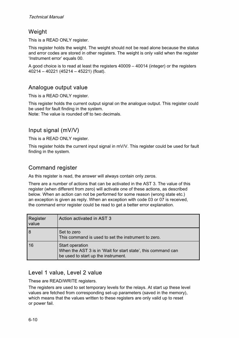
Technical Manual
6-10
Weight This is a READ ONLY register.
This register holds the weight. The weight should not be read alone because the status and error codes are stored in other registers. The weight is only valid when the register ‘Instrument error’ equals 00.
A good choice is to read at least the registers 40009 – 40014 (integer) or the registers 40214 – 40221 (45214 – 45221) (float).
Analogue output value This is a READ ONLY register.
This register holds the current output signal on the analogue output. This register could be used for fault finding in the system. Note: The value is rounded off to two decimals.
Input signal (mV/V) This is a READ ONLY register.
This register holds the current input signal in mV/V. This register could be used for fault finding in the system.
Command register As this register is read, the answer will always contain only zeros.
There are a number of actions that can be activated in the AST 3. The value of this register (when different from zero) will activate one of these actions, as described below. When an action can not be performed for some reason (wrong state etc.) an exception is given as reply. When an exception with code 03 or 07 is received, the command error register could be read to get a better error explanation.
Register value
Action activated in AST 3
8 Set to zero This command is used to set the instrument to zero.
16 Start operation When the AST 3 is in ‘Wait for start state’, this command can be used to start up the instrument.
Level 1 value, Level 2 value These are READ/WRITE registers.
The registers are used to set temporary levels for the relays. At start up these level values are fetched from corresponding set-up parameters (saved in the memory), which means that the values written to these registers are only valid up to reset or power fail.
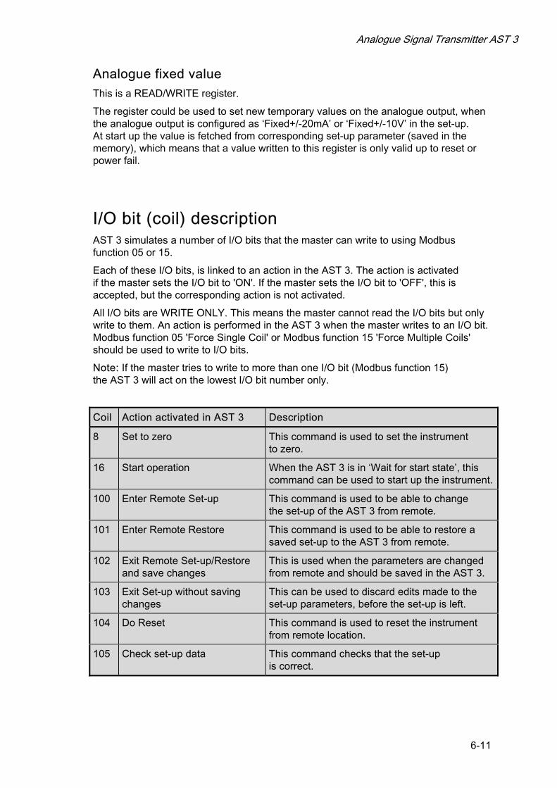
Analogue Signal Transmitter AST 3
6-11
Analogue fixed value This is a READ/WRITE register.
The register could be used to set new temporary values on the analogue output, when the analogue output is configured as ‘Fixed+/-20mA’ or ‘Fixed+/-10V’ in the set-up. At start up the value is fetched from corresponding set-up parameter (saved in the memory), which means that a value written to this register is only valid up to reset or power fail.
I/O bit (coil) description AST 3 simulates a number of I/O bits that the master can write to using Modbus function 05 or 15.
Each of these I/O bits, is linked to an action in the AST 3. The action is activated if the master sets the I/O bit to 'ON'. If the master sets the I/O bit to 'OFF', this is accepted, but the corresponding action is not activated.
All I/O bits are WRITE ONLY. This means the master cannot read the I/O bits but only write to them. An action is performed in the AST 3 when the master writes to an I/O bit. Modbus function 05 'Force Single Coil' or Modbus function 15 'Force Multiple Coils' should be used to write to I/O bits.
Note: If the master tries to write to more than one I/O bit (Modbus function 15) the AST 3 will act on the lowest I/O bit number only.
Coil Action activated in AST 3 Description
8 Set to zero This command is used to set the instrument to zero.
16 Start operation When the AST 3 is in ‘Wait for start state’, this command can be used to start up the instrument.
100 Enter Remote Set-up This command is used to be able to change the set-up of the AST 3 from remote.
101 Enter Remote Restore This command is used to be able to restore a saved set-up to the AST 3 from remote.
102 Exit Remote Set-up/Restore and save changes
This is used when the parameters are changed from remote and should be saved in the AST 3.
103 Exit Set-up without saving changes
This can be used to discard edits made to the set-up parameters, before the set-up is left.
104 Do Reset This command is used to reset the instrument from remote location.
105 Check set-up data This command checks that the set-up is correct.

Technical Manual
6-12
Exception responses When the master sends a query to a slave it expects a normal response (as described earlier). One of the following three events occur after a query from the master.
1. Normal response. The slave has received the query without communication error and can handle the query normally. The slave returns a normal response.
2. Communication error. If the slave does not receive the query due to a communication error, or detects some communication error (parity error or checksum error), no response is returned. The master should process a time-out for the query.
3. Command error. If the slave receives the query without any communication error, but cannot handle the query, e.g. if the command was not valid, the requested register number not valid or AST 3 in a mode where the command was not allowed, then the slave will return an exception response informing the master of the nature of the error.
The following exception codes are possible.
Code Name Description
01 Illegal function Not a valid function code. Valid function codes are 01, 02, 03, 05, 06, 08, 15, 16.
02 Illegal data address Not a valid data address. See ‘Register description - Process parameters’ for a list of allowed registers.
03 Illegal data value Value in data query field not valid. To get a better explanation of the error, the ‘command error’ register could be read.
07 Negative acknowledge
AST 3 has received the query but cannot perform it. To get a better explanation of the error, the ‘command error’ register could be read.

Analogue Signal Transmitter AST 3
6-13
Set-up registers Set-up registers data area All set-up parameters are saved in float format and can be read and manipulated by a remote master. Two different types of float formats are supported, which one you should use depends on your Modbus master. To be able to edit the parameters a Coil must first be set to enter set-up remote state. Note: Normally the Windows programme deltaCOM, supplied by Nobel Weighing Systems, is used to edit parameters from a remote computer, and therefore this information is only useful if you are writing your own set-up program on your master computer. Consult chapter 3 for explanation and location of each set-up parameter.
Register area Float
Register area Modicon float
Description R/W
40380 45380 First normal set-up register (normally 41000). If ‘Modicon float’ is used, add 5000 to this value.
R
40382 45382 Number of normal set-up registers. R
40384 45384 First application programme specific set-up register. If ‘Modicon float’ is used, add 5000 to this value.
R
40386 45386 Number of application specific set-up registers (normally 0).
R
40388 45388 Start of special set-up registers (used for diagnostic purposes).
R
40390 45390 Number of special set-up registers (used for diagnostic purposes).
R
40394 45394 Set-up version. R
40396 45396 Set-up data version. R
41000 – 41700 46000 – 46700 Set-up registers. Register area containing the set-up registers. See chapter 3 for an explanation of the different parameters.
R/W
How to edit set-up registers Example: Change resolution to 0.2.
• Start by setting coil 100 ‘Enter Remote Set-up’.
• Locate the resolution parameter in chapter 3. This gives modbus register 41056.
• Set resolution ‘0.2’ by sending ‘7’ to modbus register ‘41056’.
• Proceed with changes of all the parameters that are to be changed.
• Finish by setting coil 102 ‘Exit Remote Set-up/Restore and save changes’.
• The AST 3 makes a reset and the changes go into action.

Technical Manual
6-14
External display If the choice ‘External display’ is selected for parameter ‘Serialport mode’, the serial port on the AST 3 can be used for presentation of the weight on an external display unit. The transmitted weight is adapted for Newport/London large digit indicators with 4, 5, 6 or 7 digits and the Intrinsic safety indicator BA488C with 32 characters, connected through the serial communication isolator MTL5051. To get a working remote display the parameters ‘Baudrate’, ‘Data format’ and 'Ext. disp.format’ must be set to those defined by the remote display.
In the set-up parameter 'Ext disp.format’ the following formats for the transmitted weight value can be selected:
Type Description
4 (digits) Four digit indicator. Display: -999 – 9999 (plus possible decimal point).
5 (digits) Five digit indicator. Display: -9999 – 99999 (plus possible decimal point).
6 (digits) Six digit indicator. Display: -99999 – 999999 (plus possible decimal point). Possible gross/net indicators will be activated. (GROSS ONLY ON AST).
7 (digits) Seven digit indicator. Display: -999999 – 9999999 (plus possible decimal point).
32 (characters) BA488C Intrinsic safety indicator. Display: -999999 – 9999999 (plus possible dec. point).
Remote display with 4 to 7 digits The remote display normally shows the current weight, but under the following conditions only ‘dashes’ (-----) are displayed:
• the number of digits in the transmitted weight value is outside the indicators range.
• the instrument is not in normal state or there is a weight error.
Definition of weight value to large digit indicator 4, 5, 7 digits:
Character No.
Value alphanumeric.
Value Hex
Function
1 02 Start character (STX).
2 to 5 – 9 0 – 9, . , - 30 – 39, 2E, 2D
*/ Weight value: 4, 5 or 7 digits and a possible decimal point. (The first digit may be a minus sign).
Last 0D End character (CR).

Analogue Signal Transmitter AST 3
6-15
Definition of weight value to large digit indicator 6 digits:
Character No.
Value alphanumeric.
Value Hex
Function
1 02 Start character (STX).
2 H, blank 48, 20 This character is present only if 6 digits is selected in 'Ext. disp,format’. H = Left led ON, blank = led’s OFF.
3 to 8 or 9 0 – 9, . , - 30 – 39, 2E, 2D
*/ Weight value: 6 digits and a possible decimal point. (The first digit may be a minus sign).
Last 0D End character (CR).
Note: */ The number of digits in the weight value (including a minus sign, if present) will equal the number of digits selected in 'Ext. disp.format’. Leading zeros will be added to fill up to the selected number of digits. The decimal point does not occupy any digit position.
Remote display BA488C This remote must be connected through the isolator for serial communication MTL5051. It can handle digits and letters and consequently it has some extra functions. The weight value is always displayed with the selected measurement unit.

Technical Manual
6-16

Analogue Signal Transmitter AST 3
7-1
7. Troubleshooting
General AST 3 has an automatic error checking facility. This serves to facilitate trouble-shooting and to ensure that the instrument will function in the best possible manner. The error checking provides guidance on how to deal with the fault or error.
When an error occurs the signal ‘In process’ will be off, the relays will be deactivated, the analogue output will be set to 0V / 0mA and an error code will be displayed. This error code can be fetched by Modbus communication to a connected control unit. At the control unit the program may present an error description corresponding to the error code.
For an AST 3P instrument, some error codes will cause messages to be displayed, containing the kind of error, the error code and hints on how to correct the error.
The signal transmitter version AST 3B must have communication with a control unit for set-up and troubleshooting. For this reason a temporary communication setting can be arranged for AST 3B.
Error codes The error codes are divided in four groups, depending on their origin:
• Weight errors, occur when transducer signals or output values go out of given ranges.
• Start-up errors, occur only during start-up.
• General errors, usually occur due to faulty entries from the front panel, alternatively invalid data or unallowed commands from the control unit.
• Set-up errors, can only occur during instrument set-up (from the front panel or by serial communication).
On the following pages a summary of all error codes is given (note that code 000 always means 'no error').

Technical Manual
7-2
Weight errors
The indication is either temporary or stays on until the cause is cured. At AST 3P the text within ” ” is scrolled while the error code is displayed.
Error code
Explanation
000 No error. The instrument is in Operating mode and no error is detected.
001 Instrument in Remote set-up state. Weight is not valid.
003 Instrument not in normal state. Weight is not valid.
005 Overrange error. ” Reduce the load on the transducer(s) ” Overrange means that the input signal from the transducer exceeds the operating range.
007 Underrange error. ” Transducer signal below allowed range ” Underrange means that the input signal from the transducer is below the operation range.
010 Excitation short-circuit. ” Check connections ” Either a short-circuit in the excitation circuit or too many transducers connected. (A fault in a transducer or inside the signal transmitter is also possible.)
Check transducer connections. See section, 2 Installation.
011 Sense voltage error. ” Check connections ” The sense voltage is too low, unbalanced or has a reversed polarity. (A fault in a transducer or inside the signal transmitter also possible.)
Check transducer connections. See section, 2 Installation.
012 Transducer sign. error. ” Check connections ” The input signal is too high, for example due to a faulty or missing transducer connection. (A fault in a transducer or inside the signal transmitter is also possible.) Check transducer connections. See section, 2 Installation.
013 TransducerSignal out of range. The input signal is too high. (A fault in accordance with Error 012 above is also possible.)
015 TransducerSignal out of range. The input signal is too low. (A fault in accordance with Error 012 above is also possible.)

Analogue Signal Transmitter AST 3
7-3
Start-up errors
These error codes can only appear during start-up.
Error code
Explanation
080 Invalid set-up version. This error usually occurs at first start-up after a program upgrade. The actual settings have been replaced by default values. Enter set-up mode, perform the necessary editing and save the new parameter settings.
081 Invalid set-up data. Indicates faulty parameter checksum. The actual settings have been replaced by default values. Enter set-up mode, perform the necessary editing and save the new parameter settings.
083-085 Invalid factory calibration. Invalid factory calibration is a fatal error. It indicates that the range constant stored in the EEPROM during manufacture has been corrupted. Specially trained service personnel is required. The distributor must be contacted.
097 RAM error. RAM memory error is a fatal error. It indicates equipment failure which requires trained service personnel. The distributor must be contacted.
098 FLASH error. Flash memory error is a fatal error. It indicates equipment failure which requires trained service personnel. The distributor must be contacted.
099 Watchdog error. If a watchdog error appears the system will be reinitialised. The operator must then send a reset command from the control computer, or power the instrument off and on, to achieve normal operation.
The program regularly sends impulses to a special watchdog circuit to ensure that the circuits and the program operate correctly. However, if these impulses for any reason are omitted the watchdog error indication will result.

Technical Manual
7-4
General errors
These errors generally occur due to faulty entries from the front panel, alternatively invalid data or unallowed commands from the control unit.
Error code
Explanation
100 Instrument in wrong state. The transmitted command is not applicable to the present AST 3 mode.
101 Overrange entry. Value over allowed range. Compare with restrictions for the parameter.
102 Underrange entry. Value under allowed range. Compare with restrictions for the parameter.
103 Illegal start address. When writing float values or set-up values the start address of the written data must be even.
104 Illegal number of registers. When writing float values the number of registers of the written data must be even. This error can also occur when writing scaled integer values.
105 Illegal value error. When using scaled integer format the number of decimals must be less than 8.
130 Enter set-up/restore not allowed. The transmitted command is not applicable to the present AST 3 mode.
131 Exit set-up/restore not allowed. The exit set-up command is only allowed when the instrument state is ”Remote set-up state” or ”Remote restore state”.
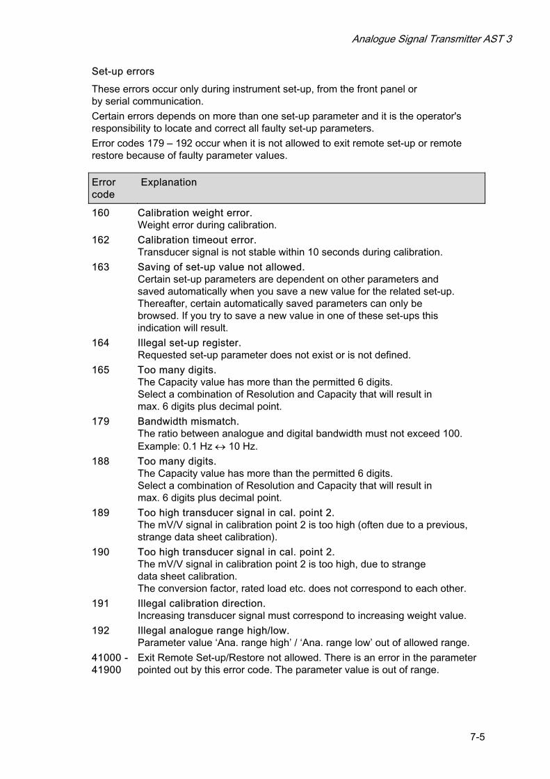
Analogue Signal Transmitter AST 3
7-5
Set-up errors
These errors occur only during instrument set-up, from the front panel or by serial communication.
Certain errors depends on more than one set-up parameter and it is the operator's responsibility to locate and correct all faulty set-up parameters.
Error codes 179 – 192 occur when it is not allowed to exit remote set-up or remote restore because of faulty parameter values.
Error code
Explanation
160 Calibration weight error. Weight error during calibration.
162 Calibration timeout error. Transducer signal is not stable within 10 seconds during calibration.
163 Saving of set-up value not allowed. Certain set-up parameters are dependent on other parameters and saved automatically when you save a new value for the related set-up. Thereafter, certain automatically saved parameters can only be browsed. If you try to save a new value in one of these set-ups this indication will result.
164 Illegal set-up register. Requested set-up parameter does not exist or is not defined.
165 Too many digits. The Capacity value has more than the permitted 6 digits. Select a combination of Resolution and Capacity that will result in max. 6 digits plus decimal point.
179 Bandwidth mismatch. The ratio between analogue and digital bandwidth must not exceed 100. Example: 0.1 Hz ↔ 10 Hz.
188 Too many digits. The Capacity value has more than the permitted 6 digits. Select a combination of Resolution and Capacity that will result in max. 6 digits plus decimal point.
189 Too high transducer signal in cal. point 2. The mV/V signal in calibration point 2 is too high (often due to a previous, strange data sheet calibration).
190 Too high transducer signal in cal. point 2. The mV/V signal in calibration point 2 is too high, due to strange data sheet calibration. The conversion factor, rated load etc. does not correspond to each other.
191 Illegal calibration direction. Increasing transducer signal must correspond to increasing weight value.
192 Illegal analogue range high/low. Parameter value ‘Ana. range high’ / ‘Ana. range low’ out of allowed range.
41000 - Exit Remote Set-up/Restore not allowed. There is an error in the parameter 41900 pointed out by this error code. The parameter value is out of range.
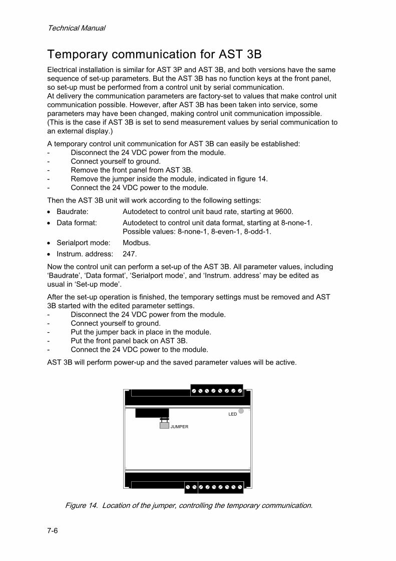
Technical Manual
7-6
Temporary communication for AST 3B Electrical installation is similar for AST 3P and AST 3B, and both versions have the same sequence of set-up parameters. But the AST 3B has no function keys at the front panel, so set-up must be performed from a control unit by serial communication. At delivery the communication parameters are factory-set to values that make control unit communication possible. However, after AST 3B has been taken into service, some parameters may have been changed, making control unit communication impossible. (This is the case if AST 3B is set to send measurement values by serial communication to an external display.)
A temporary control unit communication for AST 3B can easily be established: - Disconnect the 24 VDC power from the module. - Connect yourself to ground. - Remove the front panel from AST 3B. - Remove the jumper inside the module, indicated in figure 14. - Connect the 24 VDC power to the module.
Then the AST 3B unit will work according to the following settings:
• Baudrate: Autodetect to control unit baud rate, starting at 9600.
• Data format: Autodetect to control unit data format, starting at 8-none-1. Possible values: 8-none-1, 8-even-1, 8-odd-1.
• Serialport mode: Modbus.
• Instrum. address: 247.
Now the control unit can perform a set-up of the AST 3B. All parameter values, including ‘Baudrate’, ‘Data format’, ‘Serialport mode’, and ‘Instrum. address’ may be edited as usual in ‘Set-up mode’.
After the set-up operation is finished, the temporary settings must be removed and AST 3B started with the edited parameter settings. - Disconnect the 24 VDC power from the module. - Connect yourself to ground. - Put the jumper back in place in the module. - Put the front panel back on AST 3B. - Connect the 24 VDC power to the module.
AST 3B will perform power-up and the saved parameter values will be active.
JUMPER
LED
Figure 14. Location of the jumper, controlling the temporary communication.
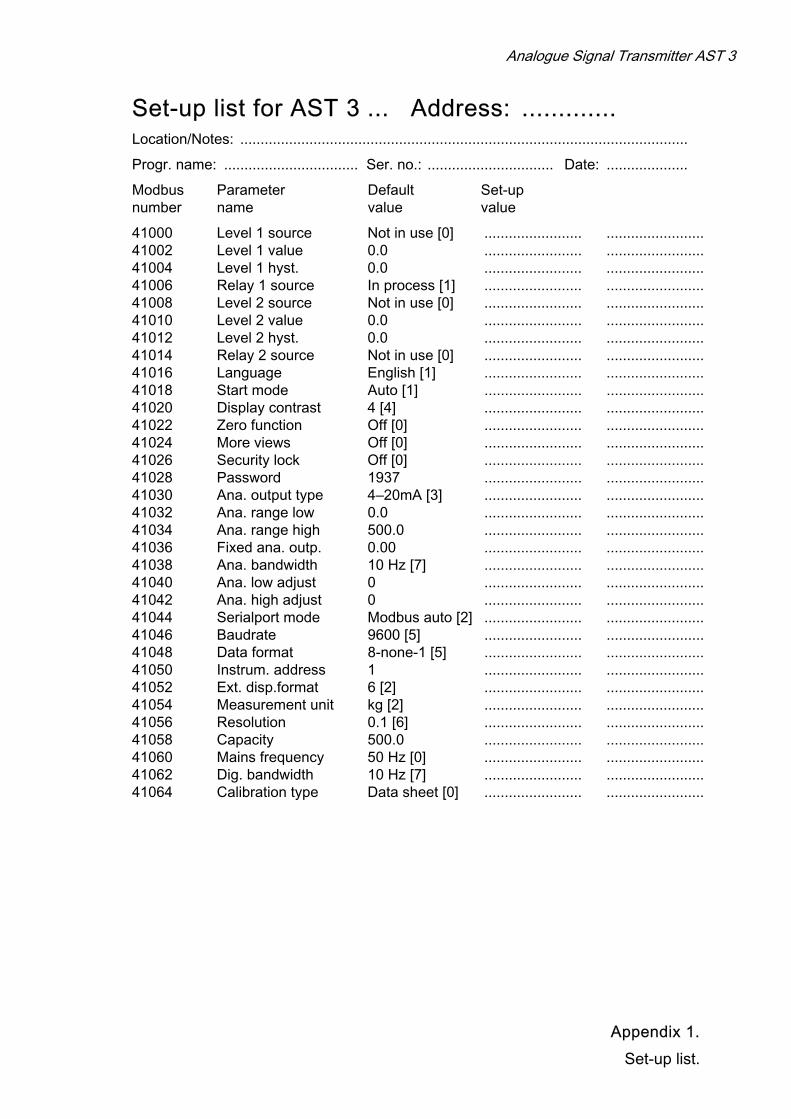
Analogue Signal Transmitter AST 3
Set-up list for AST 3 ... Address: ............. Location/Notes: ..............................................................................................................
Progr. name: ................................. Ser. no.: ............................... Date: ....................
Modbus Parameter Default Set-up number name value value
41000 Level 1 source Not in use [0] ........................ ........................ 41002 Level 1 value 0.0 ........................ ........................ 41004 Level 1 hyst. 0.0 ........................ ........................ 41006 Relay 1 source In process [1] ........................ ........................ 41008 Level 2 source Not in use [0] ........................ ........................ 41010 Level 2 value 0.0 ........................ ........................ 41012 Level 2 hyst. 0.0 ........................ ........................ 41014 Relay 2 source Not in use [0] ........................ ........................ 41016 Language English [1] ........................ ........................ 41018 Start mode Auto [1] ........................ ........................ 41020 Display contrast 4 [4] ........................ ........................ 41022 Zero function Off [0] ........................ ........................ 41024 More views Off [0] ........................ ........................ 41026 Security lock Off [0] ........................ ........................ 41028 Password 1937 ........................ ........................ 41030 Ana. output type 4–20mA [3] ........................ ........................ 41032 Ana. range low 0.0 ........................ ........................ 41034 Ana. range high 500.0 ........................ ........................ 41036 Fixed ana. outp. 0.00 ........................ ........................ 41038 Ana. bandwidth 10 Hz [7] ........................ ........................ 41040 Ana. low adjust 0 ........................ ........................ 41042 Ana. high adjust 0 ........................ ........................ 41044 Serialport mode Modbus auto [2] ........................ ........................ 41046 Baudrate 9600 [5] ........................ ........................ 41048 Data format 8-none-1 [5] ........................ ........................ 41050 Instrum. address 1 ........................ ........................ 41052 Ext. disp.format 6 [2] ........................ ........................ 41054 Measurement unit kg [2] ........................ ........................ 41056 Resolution 0.1 [6] ........................ ........................ 41058 Capacity 500.0 ........................ ........................ 41060 Mains frequency 50 Hz [0] ........................ ........................ 41062 Dig. bandwidth 10 Hz [7] ........................ ........................ 41064 Calibration type Data sheet [0] ........................ ........................
Appendix 1.
Set-up list.

Technical Manual
Set-up list for AST 3 .... Address: ............. Location/Notes: .............................................................................................................
Progr. name: ................................. Ser. no.: ............................... Date: ....................
Modbus Parameter Default Set-up number name value value
41066 Conv. factor 9.80665 ......................... ......................... 41068 Number of transd 3 ......................... ......................... 41070 Rated load 2000.0 ......................... ......................... 41072 Rated output 1 2.03900 ......................... ......................... 41074 Rated output 2 2.03900 ......................... ......................... 41076 Rated output 3 2.03900 ......................... ......................... 41078 Rated output 4 2.03900 ......................... ......................... 41080 Value cal. p.1 0.0 ......................... ......................... 41082 Value cal. p.2 500.0 ......................... ......................... 41084 Transd.sign. p.1 0.00000 ......................... ......................... 41086 Transd.sign. p.2 1.66631 ......................... ......................... 41090 Zero offset 0.00 ......................... .........................
Appendix 1.
Set-up list.

Analogue Signal Transmitter AST 3
Appendix 2.
Declaration of Conformity

Technical Manual


Vishay Nobel AB Box 423, SE-691 27 Karlskoga, Sweden Phone +46 586 63000 · Fax +46 586 63099 [email protected] www.weighingsolutions.com
Document no. 35156 Article no. 600 232 R11 © Vishay Nobel AB, 2011-05-11 Subject to changes without notice.