Embed Size (px)
Citation preview

156
Analogue Signal Processing

157
Ana
log
ue S
igna
l P
roce
ssin
g
The problem
The real world can be measured in manyways, for example, via temperature,humidity, air pressure and so forth.The parameters of these different physicalqualities change continuously. Elementsthat monitor statuses and changes in sta-tuses of a given environment, must reflectthese continual changes.Within the framework of industrial moni-toring tasks, the statuses of an environ-ment are monitored by using sensors.These sensors should provide signals thatenable connected evaluating and monitor-ing installations to draw detailed conclu-sions concerning the status of, for exam-ple, a production process. The sensor sig-nals trace the continuous changes in themonitored range. The signals can be inanalogue or digital form; which means innormal cases, an electrical voltage or cur-rent value is produced that correspondsproportionally to the monitored physicalquantities. Increasing automation with theintention of achieving or maintaining cer-tain predetermined statuses makes theprocessing of analogue values increasinglyimportant. This is also true of fieldsbeyond those where this has been neces-sary and standard for a long time, forexample, processing technology in thechemical industry. Standard electrical signal values are the norm within theframework of this processing technology.Current values from 0...20mA, 4...20 mA or voltagevalues from 0...10 V havebeen introduced as sensor output values fordiffering physical quantities. Weidmüller hastaken account the needfor increasing automationwith the processing ofthese analogue signals,and offers a wide range of products that aredesigned for handlingsensor signals.This means, units aremade available for standard signals (0...20mA, 4...20 mA, 0...10 V)that generate output signal values proportionalto the variable input signals, and at the sametime enable the safe separation of, for example, sensor circuitsof an evaluation circuit.This safe separation is
particularly important to avoid mutualinterference of multiple sensor circuits, for example, ground loops in interlinkedmeasurement circuits. The wide range ofproducts includes all functions for converting separation and monitoring signals. The different designs in connection with the respective functionscover practically all applications in industrial measurement technology.With these new products, Weidmülleroffers the possibility of taking into accountthe demands of modern automation technology with the inclusion of analoguesignals. These products guarantee an elementary function between signals fromthe field and the further processing systems. The mechanical characteristicsof these products correspond to those ofthe well-known Weidmüller products andare part of a continuous, ongoing concept. The signal conditioners can becombined together with other Weidmüllerproducts.They have been electrically and mechanically designed to ensure that onlya minimum of wiring and maintenancecosts are necessary.
The product programcontains the following functions:
Current transformerVoltage transformerThermocouple conditioners for resistance thermometersFrequency signal conditionerPotentiometer conditionerAC signal conditionerBridge measurement conditionerLimit value monitoring modulesAD/DA converter
These products are categorised accordingto functionality as pure signal conversion,2-way-isolation, 3-way-isolation and aspassive separation.
Analogue Signal Processing

158
2-way-isolation separates the signals galvanically and decouples the measurementcircuits. In so doing it eliminates potential differences caused by long cable lengths andcommon reference points. Furthermore, the galvanic isolation offers protection againstdestruction by overvoltage, and against inductive and capacitive interferences.
3-way-isolation also decouples the supply voltage from the input and output circuits,and enables the function with only one operating voltage.
The passive isolator offers a further elementary advantage; it needs no additional volt-age supply. The supply to the modules ensues via the input circuit and is the trans-ferred to the output. This current loop supply is distinguished by very low power con-sumption.
There are a large number of products available for measuring temperatures. RTDPT100 signals, in 2-, 3- and 4-wire technology, are converted to standardised 0 – 20mA, 4 – 20 mA and 0 – 10 V signals.
The modules which can be connected to commercially available thermocouples havecold junction compensation as standard. Furthermore, the modules amplify and linea-rize the voltage signals from the thermocouple. This guarantees an exact conditioningof analogue signals by eliminating sources of interference and errors.
Frequency converters convert frequencies to standard analogue signals. Thisenables controllers connected in series to directly process impulse trains when makingspeed or rotational speed measurements.
It is inconceivable to think about automation without analogue-digital-analogueconverters. To bring together the aforementioned analogue form of describing the envi-ronment and the customary digital processing, within the framework of process moni-toring, it is necessary to convert analogue signals into digital signals. Weidmüller offersmodules for the following standard input and output signals: 0...20 mA, 4...20 mA and0...10 V. 8-bit and 12-bit digital modules are available. All modules have an added inputfor making instantaneous measurements.
Current monitoring modules enable the monitoring of current values up to 60 A inalternating or direct voltages. Over range or under range values trip the switching out-put. Modules with analogue outputs enable the continuous monitoring of currents viaconnected controls.
Voltage monitoring modules can be used to monitor direct and alternating voltages.Voltage fluctuations, resulting from switching operations or network overloads, can bereliably recognised and reported via the adjustable threshold function.
Modules for monitoring of revolutions and torque enable the control of cyclic move-ments on conveyor belts, ventilators and pumps. The output responds after a setamount of time, should the expected impulse not be received. The reliable potential-free relay contact, signalises the interference to the responsible component group.
Analogue Signal Processing

159
Ana
log
ue S
igna
l P
roce
ssin
g
Design Overview
Mini Coupler / Mini Conditioner
WAVESERIES
DK Mini Coupler / MCZ Mini Conditioner
Extensive range of electronic functions in terminal formatPluggable cross-connections with mini conditionersMini couplers with screw-in cross-connection combs Mini couplers with screw connectionsMini conditioners with tension clamp connections
WAVEANALOG / WAVEANALOG PRO / WAVECONTROL
Pluggable PCB for fast service when the configuration is changedPluggable cross-connection in base socket housing to distribute the power supply, marking (CC) in the block diagram on the head platePluggable connections with optional screw or tension clamp connection
RS profiles
Analog-/Digital-Converters
Mounts onto TS 32 and TS 35 mounting railsOpen, cost-saving designVariable housing width

Function Areas of application Description Versions Page
DC signal conditioners
PT100 signal conditioners
Thermocouple conditioners
Frequency signal conditioners
AD/DA converters
Current monitoring
Voltage monitoring
Motion and rotationalspeed monitoring
Namur switching amplifier
Setpoint device
160
Signal conditioning, signal isolation, DC input/fixed functions MCZ 164suppression of mass loops and configurable inputs and WAVEANALOG 174-184
outputs WAVEANALOG PRO 185
Motor current limitation, pressure DC input/limit value DK 172alarm, direct disconnection of monitoring MCZ 173connected modules, safety function
Temperature monitoring, noise rejec- RTD input/fixed functions MCZ 165tion, electrical decoupling of visualiza- and configurable inputs and WAVEANALOG 186-188 tion devices, suppression of mass outputs WAVEANALOG PRO 189loops, heating and cooling monitoring,overheating protection of motors
Temperature monitoring, noise rejec- Thermo input/fixed functions WAVEANALOG 190tion, electrical decoupling of visualiza- and configurable inputs and WAVEANALOG PRO 191tion devices, suppression of mass outputsloops, heating and cooling monitoring, overheating protection of motors
Flow rate measurements, frequency Input/fixed functions and DK 167-168converter monitoring, speed measure- configurable inputs and MCZ 166ments, pulse processing outputs
Conditioning of voltage and current 8-bit AD/DA converter RS 210-213signals in 8-bit/12-bit digital form 12-bit AD/DA converter
Motor current monitoring, AC input/measuring of DKI 172emergency lighting monitoring sinusoidal and non sinusoidal WAVECONTROL 196-199
signals up to 60A SMSI 200-203
Under and overvoltage monitoring, One and three-phase SMSU 204-205operating status indication overvoltage
Downtime monitoring, conveyor-drive PNP/NPN or NAMUR DKLW 169monitoring, monitoring of fans, pumps input/switching output SMS 206or pistons
Switching amplifier Namur input/switching output EGV 207
Testing measuring distances, defined 1 control input/+/-set value/ EMA/SW24 208input of analogue values analogue output
Selection Table of Functions

DC/DC0…20mA 0…20mA yes Without auxiliary pwr. Fixed 6 Tens. clamp 8411190000 164
current loop supplyfrom input
0…20mA 0…20mA yes Without auxiliary pwr. Fixed 17.5 Screw/ 8444950000/ 174current loop supply tens. clamp 8444960000
from input (1-channel)0…20mA 0…20mA yes Without auxiliary pwr. Fixed 17.5 Screw/ 8463580000/ 174
current loop supply tens. clamp 8463590000
from input (2-channel)0…20mA 0…20mA 2-way 19.2…28.8Vdc/ Fixed 12.5 Screw/ 8445070000/ 176
Voltage supply of tens. clamp 8445080000
both sides0…20mA 0…20mA yes 18…30Vdc Fixed/10 Hz 17.5 Screw/ 8540180000/ 178
tens. clamp 8540190000
0…20mA 0…20mA 3-way 18…30Vdc Fixed/20 kHz 17.5 Screw/ 8447160000/ 181tens. clamp 8447170000
0…20mA 4…20mA 2-way 19.2…28.8Vdc/ Fixed 12.5 Screw/ 8446970000/ 176Voltage supply of tens. clamp 8446990000
both sides0…20mA 4…20mA yes 18…30Vdc Fixed/10 Hz 17.5 Screw/ 8540250000/ 181
tens. clamp 8540260000
0…20mA 4…20mA 3-way 18…30Vdc Fixed/20 kHz 17.5 Screw/ 8447190000/ 181tens. clamp 8447200000
0…20mA 0…10V 2-way 19.2…28.8Vdc/ Fixed 12.5 Screw/ 8447020000/ 176Voltage supply of tens. clamp 8447030000
both sides0…20mA 0…10V yes 18…30Vdc Fixed/10 Hz 17.5 Screw/ 8540270000/ 178
tens. clamp 8540280000
0…20mA 0…10V 3-way 18…30Vdc Fixed/20 kHz 17.5 Screw/ 8447220000/ 181tens. clamp 8447230000
4…20mA 0…20mA 2-way 19.2…28.8Vdc/ Fixed 12.5 Screw/ 8444980000/ 175Voltage supply of tens. clamp 8444990000
output side4…20mA 0…20mA yes 18…30Vdc Fixed/10 kHz 17.5 Screw/ 8540200000/ 179
tens. clamp 8540210000
4…20mA 0…20mA 3-way 18…30Vdc Fixed/20 kHz 17.5 Screw/ 8447250000/ 182tens. clamp 8447260000
4…20mA 4…20mA 2-way 19.2…28.8Vdc/ Fixed 12.5 Screw/ 8445010000/ 175Voltage supply of tens. clamp 8445020000
output side4…20mA 4…20mA yes 18…30Vdc Fixed/10 Hz 17.5 Screw/ 8540180000/ 178
tens. clamp 8540190000
4…20mA 4…20mA 3-way 18…30Vdc Fixed/20 kHz 17.5 Screw/ 8447160000/ 182tens. clamp 8447170000
4…20mA 0…10V 2-way 19.2…28.8Vdc/ Fixed 12.5 Screw/ 8445040000/ 175Voltage supply of tens. clamp 8445050000
output side4…20mA 0…10V yes 18…30Vdc Fixed/10 Hz 17.5 Screw/ 8540230000/ 179
tens. clamp 8540240000
4…20mA 0…10V 3-way 18…30Vdc Fixed/20 kHz 17.5 Screw/ 8447280000/ 182tens. clamp 8447290000
0…10V 0…20mA 2-way 19.2…28.8Vdc/ Fixed 12.5 Screw/ 8447050000/ 177Voltage supply of tens. clamp 8447080000
both sides0…10V 0…20mA yes 18…30Vdc Fixed/10 Hz 17.5 Screw/ 8540310000/ 180
tens. clamp 8540320000
0…10V 0…20mA 3-way 18…30Vdc Fixed/20 kHz 17.5 Screw/ 8447310000/ 183tens. clamp 8447320000
0…10V 4…20mA 2-way 19.2…28.8V/ Fixed 12.5 Screw/ 8447100000/ 177Voltage supply of tens. clamp 8447110000
both sides0…10V 4…20mA yes 18…30Vdc Fixed/10 Hz 17.5 Screw/ 8540290000/ 180
tens. clamp 8540300000
0…10V 4…20mA 3-way 18…30Vdc Fixed/20 kHz 17.5 Screw/ 8447340000/ 183tens. clamp 8447350000
0…10V 0…10V 2-way 19.2…28.8Vdc/ Fixed 12.5 Screw/ 8447130000/ 177Voltage supply of tens. clamp 8447140000
both sides
Function Input Output Galvanic Voltage supply Setting Module Connection Cat. No. Pageisolation width/mm type
Selection Table
Ana
log
ue S
igna
l P
roce
ssin
g
161
Ana
log
ue S
igna
l P
roce
ssin
g

0…10V 0…10V yes 18…30Vdc Fixed/10 Hz 17.5 Screw/ 8540330000/ 180tens. clamp 8540340000
0…10V 0…10V 3-way 18…30Vdc Fixed/20 kHz 17.5 Screw/ 8447370000/ 184tens. clamp 8447380000
Variable voltage Variable voltage yes 20…253Vdc DIP switch 12.5 Screw/ 8560740000/ 185and current and current Potentiometer tens. clamp 8560750000
(+/-20mV…+/-200V, (-10V…+10V,+/-0.1mA…+/-100mA) -20mA…+20mA)PT100/ (4)…20mA no 19.2…28.8Vdc DIP switch 12.5 Screw/ 8432210000/ 186
tens. clamp 8432220000
RTD/DCPT100/ 0…10V no 19.2…28.8Vdc DIP switch 12.5 Screw/ 8432180000/ 1862-wire Potentiometer tens. clamp 8432190000
PT100/ 4…20mA no current loop supply Fixed 6 Tens. clamp 8425720000 1652-wire in outputPT100/ 0(4)…20mA no 19.2…28.8Vdc DIP switch 12.5 Screw/ 8432150000/ 1873-wire Potentiometer tens. clamp 8432160000
PT100/ 0…10V no 19.2…28.8Vdc DIP switch 12.5 Screw/ 8432090000/ 1873-wire Potentiometer tens. clamp 8432130000
PT100/0 (4)…20mA no 19.2…28.8Vdc DIP switch 12.5 Screw/ 8432270000/ 1884-wire Potentiometer tens. clamp 8432280000
PT100/ 0…10V no 19.2…28.8Vdc DIP switch 12.5 Screw/ 8432240000/ 1884-wire Potentiometer tens. clamp 8432250000
PT100/ 0…10V yes 18…30Vdc DIP switch 17.5 Screw/ 8560700000/ 1892-/3-/4-conduct. 0…20mA Potentiometer tens. clamp 8560710000
Ni100 4…20mAPotentiometer:min. 0…100Ωmax. 0…100kΩR: 0…450Ω
Thermo/DCK, J, T, E, N,R, S, BThermo 0…10V no 19.2…28.8Vdc DIP switch 12.5 Screw/ 8432300000/ 190K, J, T, E, N, 0…20mA tens. clamp 8432310000
R, S, B 4…20mAThermocouples 0…10V yes 18…30Vdc DIP switch 17.5 Screw/ 8560720000/ 191K, J, T, E, N, 0…20mA Potentiometer tens. clamp 8560730000
R, S, B 4…20mA
Frequency/DC0...50/100/500Hz 0(4)…20mA no 21.6…26.4Vdc DIP switch 6 Screw 8311870001 1680…1/5/10/16kHz0...50/100/500Hz 0(4)…20mA no 21.6…26.4Vdc DIP switch 6 Screw 8311870001 1680…1/5/10/16kHz0...50/100/500Hz 0…10V no 21.6…26.4Vdc DIP switch 6 Screw 8283810000 1680...1/5/10/16kHz0…20mA 0...1/5/10/16kHz no 21.6…26.4Vdc DIP switch 6 Screw 8258870000 1670…20mA 0...1/5/10/16kHz no 21.6…26.4Vdc DIP switch 6 Tens. clamp 8461480000 1664…20mA 0...1/5/10/16kHz no current loop supply DIP switch 6 Screw 8081330000 167
in input4…20mA 0...1/5/10/16kHz no current loop supply DIP switch 6 Tens. clamp 8461490000 166
in input0…10V 0...1/5/10/16kHz no 21.6…26.4Vdc DIP switch 6 Screw 8242040000 1670…10V 0...1/5/10/16kHz no 21.6…26.4Vdc DIP switch 6 Tens. clamp 8461470000 166Variable, Switching output no 19.2…28.8Vdc Fixed 12 Screw 8248340000 170-programmable PNP 171
Limit value 0…20mA Switching output no 19.2…28.8Vdc Potentiometer 6 Screw 8031320000 172monitoring PNP 2-channel
0…20mA Switching output no 19.2…28.8Vdc Potentiometer 6 Tens. clamp 8227350000 173PNP 2-channel
0…10V Switching output no 19.2…28.8Vdc DIP switch 6 Screw 8019640000 172PNP 2-channel Potentiometer
0…10V Switching output no 19.2…28.8Vdc DIP switch 6 Tens. clamp 8260280000 173PNP 2-channel Potentiometer
AD convert.0…20mA 8-bit no 19.2…28.8Vdc Fixed 70 Screw 1160561001 2104…20mA 8-bit no 19.2…28.8Vdc Fixed 70 Screw 1168561001 2100…10V 8-bit no 19.2…28.8Vdc Fixed 70 Screw 1160361001 210
8-bit no 19.2…28.8Vdc Fixed 70 Screw 1122361001 2100…20mA 12-bit no 19.2…28.8Vdc Fixed 70 Screw 1168461001 2124…20mA 12-bit no 19.2…28.8Vdc Fixed 70 Screw 1169161001 2120…10V 12-bit no 19.2…28.8Vdc Fixed 70 Screw 1168361001 212
12-bit no 19.2…28.8Vdc Fixed 70 Screw 1168261001 212
Function Input Output Galvanic Voltage supply Setting Module Connection Cat. No. Pageisolation width/mm type
162
Selection Table
Function Input Output Galvanic Voltage supply Setting Module Connection Cat. No. Pageisolation width/mm type
Ana
log
ue S
igna
l P
roce
ssin
g
163
Ana
log
ue S
igna
l P
roce
ssin
g
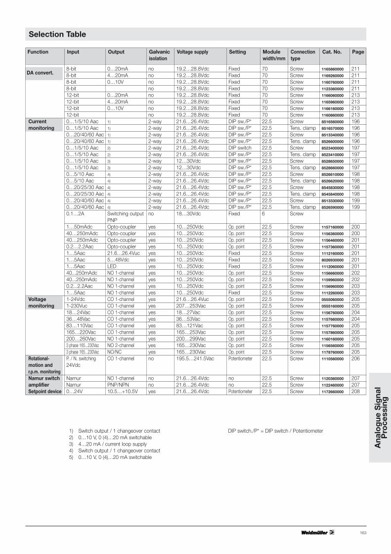
1) Switch output / 1 changeover contact2) 0…10 V, 0 (4)…20 mA switchable3) 4…20 mA / current loop supply4) Switch output / 1 changeover contact5) 0…10 V, 0 (4)…20 mA switchable
DIP switch./P* = DIP switch / Potentiometer
Selection Table
DA convert.8-bit 0…20mA no 19.2…28.8Vdc Fixed 70 Screw 1165860000 2118-bit 4…20mA no 19.2…28.8Vdc Fixed 70 Screw 1169260000 2118-bit 0…10V no 19.2…28.8Vdc Fixed 70 Screw 1160760000 2118-bit no 19.2…28.8Vdc Fixed 70 Screw 1123360000 21112-bit 0…20mA no 19.2…28.8Vdc Fixed 70 Screw 1166060000 21312-bit 4…20mA no 19.2…28.8Vdc Fixed 70 Screw 1165960000 21312-bit 0…10V no 19.2…28.8Vdc Fixed 70 Screw 1166160000 21312-bit no 19.2…28.8Vdc Fixed 70 Screw 1160860000 213
Current 0…1/5/10 Aac 1) 2-way 21.6…26.4Vdc DIP sw./P* 22.5 Screw 8516560000 196monitoring 0…1/5/10 Aac 1) 2-way 21.6…26.4Vdc DIP sw./P* 22.5 Tens. clamp 8516570000 196
0…20/40/60 Aac 1) 2-way 21.6…26.4Vdc DIP sw./P* 22.5 Screw 8513340000 1960…20/40/60 Aac 1) 2-way 21.6…26.4Vdc DIP sw./P* 22.5 Tens. clamp 8526600000 1960…1/5/10 Aac 2) 2-way 21.6…26.4Vdc DIP switch 22.5 Screw 8523400000 1970…1/5/10 Aac 2) 2-way 21.6…26.4Vdc DIP sw./P* 22.5 Tens. clamp 8523410000 1970…1/5/10 Aac 3) 2-way 12…30Vdc DIP sw./P* 22.5 Screw 8528650000 1970…1/5/10 Aac 3) 2-way 12…30Vdc DIP sw./P* 22.5 Tens. clamp 8528660000 1970…5/10 Aac 4) 2-way 21.6…26.4Vdc DIP sw./P* 22.5 Screw 8526610000 1980…5/10 Aac 4) 2-way 21.6…26.4Vdc DIP sw./P* 22.5 Tens. clamp 8526620000 1980…20/25/30 Aac 4) 2-way 21.6…26.4Vdc DIP sw./P* 22.5 Screw 8545830000 1980…20/25/30 Aac 4) 2-way 21.6…26.4Vdc DIP sw./P* 22.5 Tens. clamp 8545840000 1980…20/40/60 Aac 4) 2-way 21.6…26.4Vdc DIP sw./P* 22.5 Screw 8513330000 1990…20/40/60 Aac 4) 2-way 21.6…26.4Vdc DIP sw./P* 22.5 Tens. clamp 8526590000 1990.1…2A Switching output no 18…30Vdc Fixed 6 Screw
PNP1…50mAdc Opto-coupler yes 10…250Vdc Op. point 22.5 Screw 1157160000 20040…250mAdc Opto-coupler yes 10…250Vdc Op. point 22.5 Screw 1156360000 20040…250mAdc Opto-coupler yes 10…250Vdc Op. point 22.5 Screw 1156460000 2010.2…2.2Aac Opto-coupler yes 10…250Vdc Op. point 22.5 Screw 1157360000 2011…5Aac 21.6…26.4Vuc yes 10…250Vdc Fixed 22.5 Screw 1112160000 2011…5Aac 5…48Vdc yes 10…250Vdc Fixed 22.5 Screw 8026930000 2011…5Aac LED yes 10…250Vdc Fixed 22.5 Screw 1112060000 20140...250mAdc NO 1-channel yes 10…250Vdc Op. point 22.5 Screw 1156660000 20240...250mAdc NO 1-channel yes 10…250Vdc Op. point 22.5 Screw 1159960000 2020.2...2.2Aac NO 1-channel yes 10…250Vdc Op. point 22.5 Screw 1156960000 2031…5Aac NO 1-channel yes 10…250Vdc Fixed 22.5 Screw 1112260000 203
Voltage 1-24Vdc CO 1-channel yes 21.6…26.4Vuc Op. point 22.5 Screw 0555060000 205monitoring 1-230Vuc CO 1-channel yes 207…253Vac Op. point 22.5 Screw 0555160000 205
18…24Vac CO 1-channel yes 18…27Vac Op. point 22.5 Screw 1156760000 20436…48Vac CO 1-channel yes 36…53Vac Op. point 22.5 Screw 1157660000 20483…110Vac CO 1-channel yes 83…121Vac Op. point 22.5 Screw 1157760000 205165…220Vac CO 1-channel yes 165…253Vac Op. point 22.5 Screw 1157860000 205200…260Vac NO 1-channel yes 200…299Vac Op. point 22.5 Screw 1160160000 2053 phase 165...230Vac NO 2-channel yes 165…230Vac Op. point 22.5 Screw 1156560000 2053 phase 165...230Vac NO/NC yes 165…230Vac Op. point 22.5 Screw 1178760000 205
Rotational- P. / N. switching CO 1-channel no 195.5…241.5Vac Potentiometer 22.5 Screw 1110560000 206motion and 24Vdcr.p.m. monitoringNamur switch Namur NO 1-channel no 21.6…26.4Vdc no 22.5 Screw 1120360000 207amplifier Namur PNP/NPN no 21.6…26.4Vdc no 22.5 Screw 1122460000 207Setpoint device 0…24V 10.5…+10.5V yes 21.6…26.4Vdc Potentiometer 22.5 Screw 1172660000 208

164
Passive Isolator
Block diagram
MCZ CCC 0…20 mA/0…20 mA
Type Cat. No.
MCZ CCC 0…20 mA/0…20 mA 8411190000
without power supply
0…20 mA (max. 15 V)
< 100 µA
2.5…3 V (at 20 mA)
50 mA, 15 V
0…20 mA (max. 10 V)
approx. 5 ms at 500 Ω working resistance impedance
< 10 mVeff
approx. 200 kHz
< 0.1 % from end value, + 0.05 % from mean/100 Ω working resistance
< 50 ppm/K from measurement value for working resistance 0 Ω
510 Veff
EMVG
EN 50081-1
EN 50082-2
CE, UL, CSA
-25 °C…+40 °C
-25 °C…+50 °C
-40 °C …+85 °C
AWG 22…12
1.5 mm2
6 mm
Page 305
Ordering data
for TS 35
Technical data
Input
Response current
Voltage drop
Max. overload capacity at input
Output
Set time (T99)
Residual ripple
Chopper frequency
Transmission error
Temperature effect
Voltage strength
Input/output
EMC
Approvals
Ambient temperature
- assembled without spacing
- assembled with 20 mm spacing
Storage temperature
Conductor
Conductor cross-section
Overall width
Dimensions and accessories see
Working resistance diagram
100 500 RB (Ω)
IE = IA = 20 mA
UE (V)
This module is a reasonably priced passive separator for galvanically separating standard0.4...20 mA signals.It draws its power from the measurement signaland requires no further auxiliary power.The measurement signal is transmitted 1:1. Themodule is distinguished by its low power con-sumption as well as a response current <100 µA.
15
3

165
RTD Thermocouple Conditioners
Ana
log
ue S
igna
l P
roce
ssin
g
Block diagram
MCZ PT100/3 CLP
0…100 °C / 0…120 °C / 0…150 °C / 0…200 °C / 0…300 °C
-50…+150 °C / -40…100 °C
Type Cat. No.
MCZ PT100/3 CLP 0…100 °C 8425720000
MCZ PT100/3 CLP 0…120 °C 8483680000
MCZ PT100/3 CLP 0…150 °C 8604420000
MCZ PT100/3 CLP 0…200 °C 8473010000
MCZ PT100/3 CLP 0…300 °C 8473020000
MCZ PT100/3 CLP -50…+150 °C 8473000000
MCZ PT100/3 CLP -40…100 °C 8604430000
PT 100 (according to IEC 751)
3-wire / 2-wire*
each 50 Ω
max. 0.006 °C/Ω
0.8 mA
4…20 mA**
750 Ω at 24 V
max:30V/min:9V+20mA x RL
max: 1.5 V at 100 Hz
10 ms
Type. 0.2 % max. 0.5 % v. FSR
<0.1 % v. FSR
max. ±250 ppm/°C
yes
EMVG
EN 50081-1
EN 50082-2
CE, UL, CSA
0 °C…+50 °C
-20 °C…+85 °C
AWG 22…12
1.5 mm2
6 mm
** current loop supplied
Page 305
Ordering data
for TS 35
Technical data
Input
Connection
Max. wire resistance
Leadwire resistance effect
Supply current
Output
Load
Supply voltage
Residual ripple of supply voltage
Set time
Accuracy
Linearity
Temperature coefficient
Open circuit recognition
EMC
Approvals
Ambient temperature
Storage temperature
Conductor
Conductor cross-section
Overall width
* Putting a bridge between Pins 4 and 5
Dimensions and accessories see
The temperature module converts measurementvalues from a PT 100 into analogue measure-ment signals. The module supplies the sensorwith power. The module is distinguished by itsaccuracy and linearity.
• for 2 and 3 wire sensors
* without DC/DC converterinput supply vie current loop
166
Frequency Signal Conditioners
Ordering data
for TS 35 W
Technical data
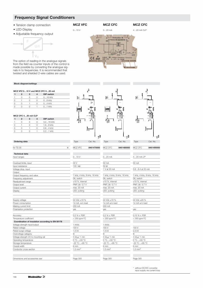
Input ranges
Overload limits, input
Input resistance
Voltage drop, input
Output
Output frequency, end value
Frequency adjustment
Readjustment range
Output level
Output current
Display
Supply voltage
Power consumption
Making current limit
Polarisation protection
Accuracy
Temperature coefficient
Coordination of insulation according to EN 50178
Voltage strength input/output
Rated voltage
Rated surge voltage
Overvoltage category
Voltage strength I/O to mounting rail
Operating temperature
Storage temperature
Overall width
Conductor cross-section
Dimensions and accessories see
Type Cat. No.
MCZ VFC 8461470000
0…10 V
30 V
100 kΩ
1 kHz, 4 kHz, 8 kHz, 16 kHz
DIL switch
±10 %, internal
PNP, Ub- 0.7 V
max. 20 mA
LED, pulsing
24 Vdc ±10 %
14 mA, w/o load
200 mA
yes
0.2 % v. FSR
< 250 ppm/°C
1 kVdc
100 V
1.5 kV
III
4 kVeff/ 1 min
0 °C…+50 °C
-25 °C…+85 °C
6 mm
1.5 mm2
Page 305
Type Cat. No.
MCZ CFC 8461480000
0…20 mA
50 mA
50 Ω
1 V at 20 mA
1 kHz, 4 kHz, 8 kHz, 16 kHz
DIL switch
±10 %, internal
PNP, Ub- 0.7 V
max. 20 mA
LED, pulsing
24 Vdc ±10 %
14 mA w/o load
200 mA
yes
0.2 % v. FSR
< 250 ppm/°C
1 kVdc
100 V
1.5 kV
III
4 kVeff/ 1 min
0 °C…+50 °C
-25 °C…+85 °C
6 mm
1.5 mm2
Page 305
Type Cat. No.
MCZ CFC 8461490000
4…20 mA LP*
50 mA
5.8…6.4 at 20 mA
1 kHz, 4 kHz, 8 kHz, 16 kHz
DIL switch
±10 %, internal
PNP, Ub- 0.7 V
max. 20 mA
LED, pulsing
24 Vdc ±20 %
14 mA w/o load
yes
0.15 % v. FSR
< 250 ppm/°C
150 V
2.5 kV
III
4 kVeff/ 1 min
0 °C…+50 °C
-25 °C…+85 °C
6 mm
1.5 mm2
Page 305
The option of reading-in the analogue signalsfrom the field via counter inputs of the control ismade possible by converting the analogue sig-nals in to frequencies. It is recommended thattwisted and shielded 2-wire cables are used.
• Tension clamp connection• LED-Display• Adjustable frequency output
MCZ CFC
0…20 mA
MCZ CFC
4…20 mA CLP
MCZ VFC
0…10 V
MCZ VFZ 0…10 V and MCZ CFC 0…20 mA
1 2 3 4 DIP switch
1 0 0 0 0…16 kHz
0 1 0 0 0…8 kHz
0 0 1 0 0…4 kHz
0 0 0 1 0…1 kHz
MCZ CFC 4…20 mA CLP
1 2 3 4 DIP switch
1 0 0 0 3.2…16 kHz
0 1 0 0 1.6…8 kHz
0 0 1 0 0.8…4 kHz
0 0 0 1 0.2…1 kHz
Block diagram/settings

• Screw connection
• LED-Display
• Adjustable frequency output
167
Frequency Signal Conditioners
Ana
log
ue S
igna
l P
roce
ssin
g
DKA U/f and DKA I/f
1 2 3 4 DIP switch
1 0 0 0 0…16 kHz
0 1 0 0 0…8 kHz
0 0 1 0 0…4 kHz
0 0 0 1 0…1 kHz
Block diagram/settings
Ordering data
for TS 32 Y
for TS 35 W
with combi foot TS 32/TS 35
Technical data
Input ranges
Overload limits, input
Input resistance
Voltage drop, input
Output
Output frequency, end value
Frequency adjustment
Readjustment range
Output level
Output current
Display
Decoupling diode
Supply voltage
Power consumption
Making current limit
Polarisation protection
Accuracy
Coordination of insulation to DIN VDE 0160, Draft 11/94
Voltage strength input/output
Rated voltage
Rated surge voltage
Overvoltage category
Voltage strength to mounting rail
Operating temperature
Storage temperature
Overall width
Conductor cross-section
Accessories
End plate
Dimensions and accessories see
Type Cat. No.
DKA U/f 8242040000
0…10 V
100 V
100 kΩ
1 kHz, 4 kHz, 8 kHz, 16 kHz
DIL switch
±10 %, internal
PNP, Ub- 0.7 V
max. 20 mA
LED, pulsing
present
24 Vdc ±10 %
14 mA, w/o load
200 mA
yes
0.2 % v. FSR
<250 ppm/°C
1 kVdc
4 kVeff
0 °C…+50 °C
-25 °C…+60 °C
6 mm
0.5…4 mm2
Type Cat. No.
AP DK5 8268870000
Page 305
Type Cat. No.
DKA I/f 8258870000
0…20 mA
50 mA
50 Ω
1 V at 20 mA
1 kHz, 4 kHz, 8 kHz, 16 kHz
DIL switch
±10 %, internal
PNP, Ub- 0.8 V
max. 20 mA
LED, pulsing
present
24 Vdc ±10 %
14 mA w/o load
200 mA
yes
0.2 % v. FSR
<250 ppm/°C
1 kVdc
4 kVeff
0 °C…+50 °C
-25 °C…+60 °C
6 mm
0.5…4 mm2
Type Cat. No.
AP DK5 8268870000
Page 305
Type Cat. No.
DKA I/f * 8081330000
4…20 mA
50 mA
max. 320 Ω at 20 mA
max. 6.4 V at 20 mA
5 kHz (1…5 kHz)
Ub- 3 V
max. 20 mA
present
19.2…28.8 Vdc
<13 mA w/o load
yes
0.15 % v. FSR
<250 ppm/°C 2
4 kVeff
150 V
2.5 kV
III
4 kVeff
0 °C…+50 °C
-25 °C…+60 °C
6 mm
0.5…4 mm2
Type Cat. No.
AP DK5 8268870000
Page 305
DKA I/f DKA I/f*DKA U/f
For EMC reasons, frequency processing mod-ules must be used in conjunction with shieldedcables. This measure prevents interference ofanalogue and frequency signals by other signalcables and vice versa.
* without DC/DC converterInput current loop supplied

168
Frequency Signal Conditioners
Ordering data
for TS 32 Y
for TS 35 W
with combi foot TS 32/TS 35
Technical data
Input ranges
Overload limits, input
Input resistance
Voltage drop, input
Output
Output frequency, end value
Frequency adjustment
Readjustment range
Output level
Output current
Display
Decoupling diode
Supply voltage
Power consumption
Making current limit
Polarisation protection
Accuracy
Coordination of insulation to DIN VDE 0160, Draft 11/94
Voltage strength input/output
Rated voltage
Rated surge voltage
Overvoltage category
Voltage strength to mounting rail
Operating temperature
Storage temperature
Overall width
Conductor cross-section
Dimensions and accessories see
DKA f/U
Type Cat. No.
DKA f/U 8283810001
0…50/100/500 Hz
0…1/5/10/16 kHz
10 kΩ
0/2…10 V
DIL switch
24 Vdc ±10 %
32 mA + ILoad
yes
0.5 % (8-bit resolution)
2.5 kV
4 kVeff
0 °C…+50 °C
-25 °C…+60 °C
6 mm
0.5…4 mm2
Page 305
DKA f/I
Type Cat. No.
DKA f/I 8311870001
0…50/100/500 Hz
0…1/5/10/16 kHz
10 kΩ
0/4…20 mA
DIL switch
24 Vdc ±10 %
32 mA + ILoad
yes
0.5 % (8-bit resolution)
2.5 kV
4 kVeff
0 °C…+50 °C
-25 °C…+60 °C
6 mm
0.5…4 mm2
Page 305
1 2 3 4 DIP switch0 0 0 X 0…50 Hz1 0 0 X 0…100 Hz0 1 0 X 0…500 Hz1 1 0 X 0…1 kHz0 1 1 X 0…5 kHz1 0 1 X 0…10 kHz1 1 1 X 0…16 kHz0 0 1 X Customer specificX X X 0 0…20 mA / 0…10 VX X X 1 4…20 mA / 2…10 V
For EMC reasons, frequency processing mod-ules must be used in conjunction with shieldedcables. This measure prevents interference ofanalogue and frequency signals by other signalcables and vice versa.
Block diagram/settings
• Screw connection • LED-Display• Adjustable frequency output • multiplex capable

169
Ana
log
ue S
igna
l P
roce
ssin
g
Ordering data
for TS 32 Y
for TS 35 W
Technical data
Input
Number of inputs
Input frequency
Range selection
Fine adjustment
Input nominal level
Overload limits
Switching threshold
Pulse duration
Input current
Reverse polarity protection
Output
Function
Output level
Output current
Decoupling diode
Status LED
Short-circuit proof
Operating voltage
Power consumption
Reverse polarity protection
Galvanic isolation
Voltage strength to mounting rail
Operating temperature
Storage temperature
Overall width
Conductor cross-section
Insulation stripping length
Others
Accessories
End plate
Dimensions and accessories see
Type Cat. No.
DK LW 8258680000
Initiators, NPN or PNP
1
10 - 6250 U/min.
3 switchable revolutions ranges: 10-130, 100-1300, 1000-7800 r.p.m.
2 potentiometers for upper/lower revs limit
24 Vdc = High, O V = Low
30 Vdc
High >18 V, Low <7 V
>0.5 ms
approx. 3.5 mA (24 V)
yes
Optional PNP or NPN
Output active, if f within set revs limit
Ub- 1.8 V
20 mA max.
yes
green LED
no
24 V –10 % + 20 %
<10 mA, w/o load, without initiator
yes
no
4 kVeff
0…+50 °C
-40…+60 °C
12 mm
0.5…4 mm2
7 mm
Initiator power supply via module possible
Type Cat. No.
AP DKT4 0687560000
Page 278
Monitoring Revolutions
DK LW
If only one revolution limit is to be evaluated, thepotentiometer for fmax must be set to end stopor the potentiometer for fmin to left stop. Thenonly the other is in each case active for settingthe limit value.
Block diagram/settings

170
Preprocessing Logic
Ordering data
for TS 32 Y
for TS 35 W
Technical data
Logical function
Number of inputs
Input nominal level
Overload limits
Switching threshold
Pulse duration
Input current
Output
Output level
Output current
Decoupling diode
Status LED
Short-circuit proof
Operating voltage
Power consumption
Reverse polarity protection
Galvanic isolation
Voltage strength to mounting rail
Operating temperature
Storage temperature
Overall width
Conductor cross-section
Insulation stripping length
Accessories
End plate
Ordering example: RS FLIP-FLOP
Dimensions see
Type Cat. No.
on request
DK PL 8248340000*
Programmable, see note
5
24 Vdc = High, 0 V = Low
30 Vdc
High >18 V, Low <7 V
>1 ms
approx. 1.5 mA per input (24 V)
PNP
Ub- 1 V
20 mA max.
no
green LED
no
24 V ±20 %
<10 mA
yes
no
4 kVeff
0 °C…+50 °C
-40 °C…+60 °C
12 mm
0.5…4 mm2
7 mm
Type Cat. No.
AD DKT4 0687560000
8248340002
Page 278
DK PL•Screw connection
• logic function and time functioncombined
• individually programmable(further functions on request)
Block diagram
* (not programmed - function next page)
171
Ana
log
ue S
igna
l P
roce
ssin
g
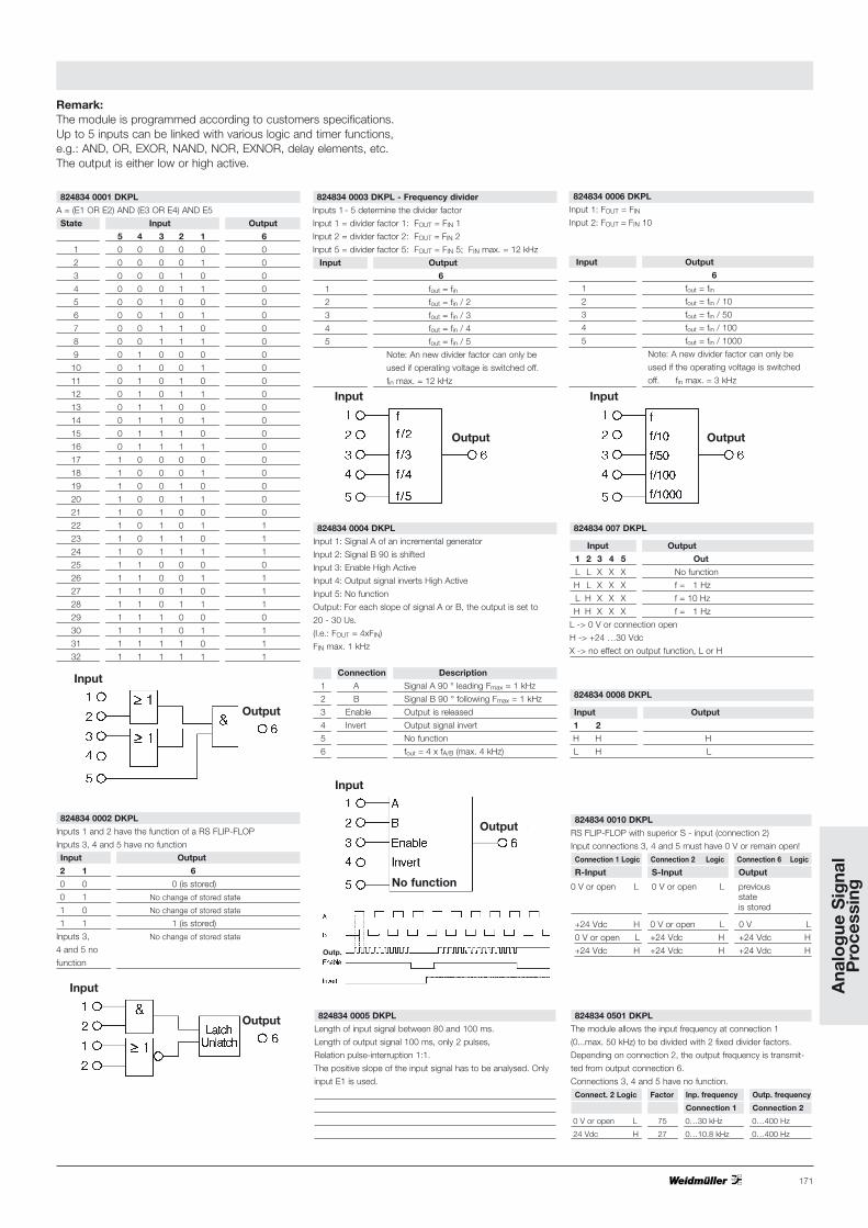
Remark:The module is programmed according to customers specifications. Up to 5 inputs can be linked with various logic and timer functions,e.g.: AND, OR, EXOR, NAND, NOR, EXNOR, delay elements, etc.The output is either low or high active.
824834 0002 DKPL
Inputs 1 and 2 have the function of a RS FLIP-FLOP
Inputs 3, 4 and 5 have no function
Input Output
2 1 6
0 0 0 (is stored)
0 1 No change of stored state
1 0 No change of stored state
1 1 1 (is stored)
Inputs 3, No change of stored state
4 and 5 no
function
824834 0001 DKPL
A = (E1 OR E2) AND (E3 OR E4) AND E5
State Input Output
5 4 3 2 1 6
1 0 0 0 0 0 0
2 0 0 0 0 1 0
3 0 0 0 1 0 0
4 0 0 0 1 1 0
5 0 0 1 0 0 0
6 0 0 1 0 1 0
7 0 0 1 1 0 0
8 0 0 1 1 1 0
9 0 1 0 0 0 0
10 0 1 0 0 1 0
11 0 1 0 1 0 0
12 0 1 0 1 1 0
13 0 1 1 0 0 0
14 0 1 1 0 1 0
15 0 1 1 1 0 0
16 0 1 1 1 1 0
17 1 0 0 0 0 0
18 1 0 0 0 1 0
19 1 0 0 1 0 0
20 1 0 0 1 1 0
21 1 0 1 0 0 0
22 1 0 1 0 1 1
23 1 0 1 1 0 1
24 1 0 1 1 1 1
25 1 1 0 0 0 0
26 1 1 0 0 1 1
27 1 1 0 1 0 1
28 1 1 0 1 1 1
29 1 1 1 0 0 0
30 1 1 1 0 1 1
31 1 1 1 1 0 1
32 1 1 1 1 1 1
824834 0003 DKPL - Frequency divider
Inputs 1 - 5 determine the divider factor
Input 1 = divider factor 1: FOUT = FIN 1
Input 2 = divider factor 2: FOUT = FIN 2
Input 5 = divider factor 5: FOUT = FIN 5; FIN max. = 12 kHz
Input Output
6
1 fout = fin2 fout = fin / 2
3 fout = fin / 3
4 fout = fin / 4
5 fout = fin / 5
Note: An new divider factor can only be
used if operating voltage is switched off.
fin max. = 12 kHz
824834 0004 DKPL
Input 1: Signal A of an incremental generator
Input 2: Signal B 90 is shifted
Input 3: Enable High Active
Input 4: Output signal inverts High Active
Input 5: No function
Output: For each slope of signal A or B, the output is set to
20 - 30 Us.
(I.e.: FOUT = 4xFIN)
FIN max. 1 kHz
Connection Description
1 A Signal A 90 ° leading Fmax = 1 kHz
2 B Signal B 90 ° following Fmax = 1 kHz
3 Enable Output is released
4 Invert Output signal invert
5 No function
6 fout = 4 x fA/B (max. 4 kHz)
824834 0006 DKPL
Input 1: FOUT = FIN
Input 2: FOUT = FIN 10
Input Output
6
1 fout = fin2 fout = fin / 10
3 fout = fin / 50
4 fout = fin / 100
5 fout = fin / 1000
Note: A new divider factor can only be
used if the operating voltage is switched
off. fin max. = 3 kHz
824834 007 DKPL
Input Output
1 2 3 4 5 Out
L L X X X No function
H L X X X f = 1 Hz
L H X X X f = 10 Hz
H H X X X f = 1 Hz
L -> 0 V or connection open
H -> +24 …30 Vdc
X -> no effect on output function, L or H
824834 0005 DKPL
Length of input signal between 80 and 100 ms.
Length of output signal 100 ms, only 2 pulses,
Relation pulse-interruption 1:1.
The positive slope of the input signal has to be analysed. Only
input E1 is used.
824834 0501 DKPL
The module allows the input frequency at connection 1
(0...max. 50 kHz) to be divided with 2 fixed divider factors.
Depending on connection 2, the output frequency is transmit-
ted from output connection 6.
Connections 3, 4 and 5 have no function.
Connect. 2 Logic Factor Inp. frequency Outp. frequency
Connection 1 Connection 2
0 V or open L 75 0…30 kHz 0…400 Hz
24 Vdc H 27 0…10.8 kHz 0…400 Hz
824834 0010 DKPL
RS FLIP-FLOP with superior S - input (connection 2)
Input connections 3, 4 and 5 must have 0 V or remain open!
Connection 1 Logic Connection 2 Logic Connection 6 Logic
R-Input S-Input Output
0 V or open L 0 V or open L previous state is stored
+24 Vdc H 0 V or open L 0 V L
0 V or open L +24 Vdc H +24 Vdc H
+24 Vdc H +24 Vdc H +24 Vdc H
824834 0008 DKPL
Input Output
1 2
H H H
L H L
InputInput
InputOutput
InputInput
InputOutput
InputInput
InputOutput
InputInput
InputOutput
InputInput
InputOutput
InputNo function
Outp.

172
Ordering data
for TS 32 Y
for TS 35 W
with combi foot TS 32/TS 35
Technical data
Input signal
Input resistance
Voltage drop, input
Cut-off frequeny
Switchable input range
Switching point settings
Hysteresis
Output
Output level
Output current
Function
Status LED
Operating voltage
Power consumption
Galvanic isolation
Voltage strength to mounting rail
Operating temperature
Storage temperature
Overall width
Conductor cross-section
EMC resistance
Burst acc. to EN 61000-4-4 Input/outputs
Power supply
ESD acc. to EN 61000-4-2 Contact discharge
Air discharge
Accessories
End plate
Dimensions see
Type Cat. No.
DKSC 0-10 V 8019640000
0…10 V
60 kΩ
100 Hz
DIL switch for 3 ranges
2 threshold Uth 1 and Uth 2
with 2 front potentiometers
each 1 %
double switch output
per PNP, Ub- 1.2 V
50 mA
Uin <Uth1: output 1 active
Uin >Uth2: output 2 active
no
24 Vdc ±20 %
approx. 15 mA
no
4 kVeff
0 °C…+50 °C
-25 °C…+60 °C
6 mm
0.5…4 mm2
Test severity 4, self restoring
Test severity 4, self restoring
Test severity 4
Test severity 3
Type Cat. No.
AP DK5 8268870000
Page 278
Type Cat. No.
DKSC 0-20 mA 8031320000
0(4)…20 mA
50 Ω
1 V
100 Hz
2 threshold Uth 1 and Uth 2
with 2 front potentiometers
each 1 %
double switch output
per PNP, Ub- 1.2 V
50 mA
Iin <Ith1: output 1 active
Iin >Ith2: output 2 active
no
24 Vdc ±20 %
approx. 15 mA
no
4 kVeff
0 °C…+50 °C
-25 °C…+60 °C
6 mm
0.5…4 mm2
Type Cat. No.
AP DK5 8268870000
Page 278
Type Cat. No.
DKI 2A 8017400000
DKI 2A 8017410000
0.1…2 A
125 mV at 2 A
no
Fixed:ON >90 mA
OFF <50 mA
single switch output
PNP, Ub-0.1 V
20 mA
green LED
18…30 Vdc
approx. 10 mA
no
4 kVeff
-25 °C…+50 °C
-40 °C…+85 ° C
6 mm
0.5…4 mm2
Type Cat. No.
AP DKT4 0687560000
Page 278
Threshold Monitoring
DKSC 0-20 mA DKI 2A
• Screw connection
• Mounts onto on mounting rail
• Wide spectrum of functions
• In part, individually adjustable
DKSC 0-10 V
S1 S2 DIP switch
on on 10…100 mV
on off 30 mV…1 V
off X 300 mV…10 V
Block diagram/settings
Current sensor

173
Threshold Monitoring
Ana
log
ue S
igna
l P
roce
ssin
g
Block diagram
MCZ SC 0…10 Vdc
Type Cat. No.
MCZ SC 24 V/0…10V 8260280000
24 Vdc ± 20 %
15 mA
0…10 V
60 kΩ
100 Hz
S1 S2 Temperature coefficient Tk
10…100 mV on on 500 ppm max.
0.03…1 V on off 250 ppm max.
0.3…10 V off x 250 ppm max.
via 2 potentiometers (12 turns)
1 % of the end value
active High for UInput < Uth1 (set via P1)
active High for UInput > Uth2 (set via P2)
< 250 µs (switch threshold at 90% of the max. input signal;
RL ≤ 1 kΩ)
2 channel switching PNP
max. 50 mA
< 1.2 V at 50 mA
none
4 kVeff / 1 min
0 °C…+50 °C
-25 °C…+60 °C
AWG 22…12
1.5 mm2
CE, UL, CSA
6 mm
Page 305
Type Cat. No.
MCZ SC 24 V/0…20 mA 8227350000
24 Vdc ± 20 %
15 mA
0.5…20 mA
50 Ω
1 V
40 mA
100 Hz
Temperature coefficient Tk 250 ppm max.
via 2 potentiometers (12 turns)
1 % of the end value
active High for IInput < I th1 (set via P1)
active High for IInput > I th2 (set via P2)
< 250 µs (switch threshold at 90% of the max. input signal;
RL ≤ 1 kΩ)
2 channel switching PNP
max. 50 mA
< 1.2 V at 50 mA
none
4 kVeff / 1 min
0 °C…+50 °C
-25 °C…+60 °C
AWG 22…12
1.5 mm2
CE, UL, CSA
6 mm
Page 305
Ordering data
for TS 35
Technical data
Voltage supply
Supply voltage
Supply current
Input
Input voltage
Input resistance
Voltage drop at full scale
Max. input current
Cut-off frequeny
Transmission behaviour
Threshold voltage ranges of Uth
Setting of switching threshold
Hysteresis of switching threshold
Function of output 1
Function of output 2
Response time
Output
Output current per output
Voltage drop at output transistor
Insulation coordination/safe separation to EN 50178
Separation input / output
Dielectric strength I/O to mounting rail
Ambient temperature
Storage temperature
Conductor
Conductor cross-section
Approvals
Overall width
Dimensions and accessories see
MCZ SC 0…20 mA
The Setpoint Controller allows cost effective unitsto be built for monitoring analogue signals. Anupper and lower limit value, which covers the en-tire signal range, can be set by the user via2 potentiometers. The respective statuses of theupper and lower limit value are indicated at the 2digital outputs (upper limit value under/over flow;lower limit value under/over flow).

174
Passive Isolator DC/DC
Block diagram
Type Cat. No.
WAS5 CCC LP 8463580000
WAZ5 CCC LP 8463590000
0(4) ... 20 mA / 0(4) ... 20 mA
0 ... 20 mA (4 ... 20 mA)
18 V
50 mA
< 100 µA
approx. 3 V at RL= 0 Ω
Iin = 20 mA
approx. 13 V at RL= 500 Ω
at Iin = 20 mA
0 ... 20 mA (4 ... 20 mA)
≤ 500 Ω
< 0.1% of FS
< 0.1% from measurement value
per 100 Ω load resistance
50 ppm / K of FS
4.5 ms at 500 Ω working resistance
< 20 mVeff
approx. 170 kHz
-25 °C ... +70 °C
-40 °C ... +80 °C
92.4 / 112.5 / 17.5
CE, UL, CSA, GL
300 V
6 kV
III
2
≥ 5.5 mm
4 kVeff / 1 s
4 kVeff / 1 min
EN 50178 (safe separation)
EN 50081, EN 50082,
EN 55011
Page 298 + 308
Type Cat. No.
WAS5 CCC LP 8444950000
WAZ5 CCC LP 8444960000
0(4) ... 20 mA / 0(4) ... 20 mA
0 ... 20 mA (4 ... 20 mA)
18 V
50 mA
< 100 µA
approx. 3 V at RL= 0 Ω
Iin = 20 mA
approx. 13 V at RL= 500 Ω
at Iin = 20 mA
0 ... 20 mA (4 ... 20 mA)
≤ 500 Ω
< 0.1% of FS
< 0.1% from measurement value
per 100 Ω load resistance
50 ppm / K of FS
4.5 ms at 500 Ω working resistance
< 20 mVeff
approx. 170 kHz
-25 °C ... +70 °C
-40 °C ... +80 °C
92.4 / 112.5 / 17.5
CE, UL, CSA, GL
300 V
6 kV
III
2
≥ 5.5 mm
4 kVeff / 1 s
4 kVeff / 1 min
EN 50178 (safe separation)
EN 50081, EN 50082,
EN 55011
Page 298 + 308
CCC LP (1 channel)0(4) ... 20 mA / 0(4) ... 20 mA
CCC LP (2 channel)0(4) ... 20 mA / 0(4) ... 20 mA
WAVEANALOG DC/DC
input loop poweredgalvanic isolation1-, 2-channel versionslow power consumptionsafe separation
Ordering data
Screw connection 1 channel
Tension clamp connection 1 channel
Screw connection 2 channel
Tension clamp connection 2 channel
Input/output
Technical data* (per channel)
Input signal
Input voltage max.
Input current max
Operating current
Voltage drop
Output signal
Load resistance
Accuracy at Tu=23 °C
Influence of load resistance
Temperature coefficient
Set time
Residual ripple
Chopper frequency
General
Operating temperature
Storage temperature
Dimensions L / H / W mm
Approvals
Rated voltage
Rated surge voltage
Overvoltage category
Contamination class
Clearance and creepage distance
Isolation voltage, voltage strength
Input/output, channel / channel
Input/output to mounting rail
Standards/specifications
EMC standards
Dimensions and accessories see
*TU = 23 °C single module
Coordination of insulation according to EN 50178, 04/98 (safe separation)
Approvals:

Ana
log
ue S
igna
l P
roce
ssin
g
175
Block diagram
CCC DC4 ... 20 mA / 4 ... 20 mA
CCC DC4 ... 20 mA / 0 ... 20 mA
CVC DC4 ... 20 mA / 0 ... 10 V
WAVEANALOG DC/DC
voltage supply on output side2-way-isolationanalogue signal conditioning galvanic isolation betweeninput/output signalInput loop poweredcross-connectable voltage supply via cross-connectors
Ordering data
Screw connection
Tension clamp connection
Input/output
Technical data*
Input signal
Input voltage max.
Input current max
Output signal
Load resistance
Accuracy at Tu=23 °C
Temperature coefficient
Response time
Cut-off frequeny (-3 dB)
General
Voltage supply
Power consumption
Current carrying capacity of cross-connection
Operating temperature
Storage temperature
Dimensions L / H / W mm
Approvals
Coordination of insulation according to EN 50178, 04/98
Rated voltage
Rated surge voltage
Overvoltage category
Contamination class
Clearance and creepage distance
Isolation voltage, voltage strength
Input/output to mounting rail
Standards/specifications
EMC standards
Dimensions and accessories see
*TU = 23 °C single module
Type Cat. No.
WAS4 CVC DC 8445040000
WAZ4 CVC DC 8445050000
4 ... 20 mA / 0 ... 10V
4 ... 20 mA
7 V
25 mA
0 ... 10 V
≥ 1 kΩ
± 0.2% of FS
≤ 250 ppm / K of FS
≤ 30 ms (typ. 20 ms)
≥ 15 Hz (typ. 20 Hz)
24 Vdc ±20%
(19.2 ... 28.8 Vdc)
< 20 mA at Iout = 10 mA
≤ 2 A
0 °C ... +55 °C (mounted)
-20 °C ... +85 °C
92.4 / 112.5 / 12.5
CE, UL, CSA
300 V
4 kV
III
2
≥ 3 mm
4 kVeff / 1 min
EN 50178
EN 50081, EN 50082,
EN 55011
Page 298 + 308
Type Cat. No.
WAS4 CCC DC 8445010000
WAZ4 CCC DC 8445020000
4 ... 20 mA / 0 ... 20 mA
4 ... 20 mA
7 V
25 mA
0 ... 20 mA
≤ 500 Ω
± 0.2% of FS
≤ 250 ppm / K of FS
≤ 30 ms (typ. 20 ms)
≥ 15 Hz (typ. 20 Hz)
24 Vdc ±20%
(19.2 ... 28.8 Vdc)
< 32 mA at Iout = 20 mA
≤ 2 A
0 °C ... +55 °C (mounted)
-20 °C ... +85 °C
92.4 / 112.5 / 12.5
CE, UL, CSA
300 V
4 kV
III
2
≥ 3 mm
4 kVeff / 1 min
EN 50178
EN 50081, EN 50082,
EN 55011
Page 298 + 308
Type Cat. No.
WAS4 CCC DC 8444980000
WAZ4 CCC DC 8444990000
4 ... 20 mA / 4...20 mA
4 ... 20 mA
7 V
25 mA
4 ... 20 mA
≤ 500 Ω
± 0.2% of FS
≤ 250 ppm / K of FS
≤ 30 ms (typ. 20 ms)
≥ 15 Hz (typ. 20 Hz)
24 Vdc ±20%
(19.2 ... 28.8 Vdc)
< 32 mA at Iout = 20 mA
≤ 2 A
0 °C ... +55 °C (mounted)
-20 °C ... +85 °C
92.4 / 112.5 / 12.5
CE, UL, CSA
300 V
4 kV
III
2
≥ 3 mm
4 kVeff / 1 min
EN 50178
EN 50081, EN 50082,
EN 55011
Page 298 + 308
DC/DC-Signal Conditioners
Approvals:

176
Block diagram
Ordering data
Screw connection
Tension clamp connection
Input/output
Technical data*
Input signal
Input current max
Input resistance
Output signal
Load resistance
Accuracy at Tu=23 °C
Temperature coefficient
Response time
Cut-off frequeny (-3 dB)
General
Voltage supply
Power consumption input
Power consumption output
Current carrying capacity of cross-connection
Operating temperature
Storage temperature
Dimensions L / H / W mm
Approvals
Coordination of insulation according to EN 50178, 04/98
Rated voltage
Rated surge voltage
Overvoltage category
Contamination class
Clearance and creepage distance
Isolation voltage, voltage strength
Input/output to mounting rail
Standards/specifications
EMC standards
Dimensions and accessories see
*TU = 23 °C single module
CCC DC CCC DC CVC DC0 ... 20 mA / 0 ... 20 mA 0 ... 20 mA / 4 ... 20 mA 0 ... 20 mA / 0 ... 10 V
WAVEANALOG DC/DC
voltage supply on both sides 2-way-isolationanalogue signal conditioninggalvanic isolation betweeninput/output signalcross-connectable voltage supply via cross-connectorss
Type Cat. No.
WAS4 CVC DC 8447020000
WAZ4 CVC DC 8447030000
0 ... 20 mA / 0 ... 10 V
0 ... 20 mA
25 mA
50 Ω
0 ... 10 V
≥ 1 kΩ
± 0.2% of FS
≤ 250 ppm / K of FS
≤ 30 ms (typ. 16 ms)
≥ 15 Hz (typ. 25 Hz)
24 Vdc ±20%
(19.2 ... 28.8 Vdc)
< 11 mA at Iin = 20 mA
< 20 mA at Iout = 10 V
≤ 2 A
0 °C ... +55 °C (mounted)
-20 °C ... +85 °C
92.4 / 112.5 / 12.5
CE, UL, CSA
300 V
4 kV
III
2
≥ 3 mm
4 kVeff / 1 min
EN 50178
EN 50081, EN 50082,
EN 55011
Page 298 + 308
Type Cat. No.
WAS4 CCC DC 8446970000
WAZ4 CCC DC 8446990000
0 ... 20 mA / 4 ... 20 mA
0 ... 20 mA
25 mA
50 Ω
4 ... 20 mA
≤ 500 Ω
± 0.2% of FS
≤ 250 ppm / K of FS
≤ 30 ms (typ. 16 ms)
≥ 15 Hz (typ. 25 Hz)
24 Vdc ±20%
(19.2 ... 28.8 Vdc)
< 11 mA at Iin = 20 mA
< 32 mA at Iout = 20 mA
≤ 2 A
0 °C ... +55 °C (mounted)
-20 °C ... +85 °C
92.4 / 112.5 / 12.5
CE, UL, CSA
300 V
4 kV
III
2
≥ 3 mm
4 kVeff / 1 min
EN 50178
EN 50081, EN 50082,
EN 55011
Page 298 + 308
Type Cat. No.
WAS4 CCC DC 8445070000
WAZ4 CCC DC 8445080000
0 ... 20 mA / 0 ... 20 mA
0 ... 20 mA
25 mA
50 Ω
0 ... 20 mA
≤ 500 Ω
± 0.2% of FS
≤ 250 ppm / K of FS
≤ 30 ms (typ. 16 ms)
≥ 15 Hz (typ. 25 Hz)
24 Vdc ±20%
(19.2 ... 28.8 Vdc)
< 11 mA at Iin = 20 mA
< 32 mA at Iout = 20 mA
≤ 2 A
0 °C ... +55 °C (mounted)
-20 °C ... +85 °C
92.4 / 112.5 / 12.5
CE, UL, CSA
300 V
4 kV
III
2
≥ 3 mm
4 kVeff / 1 min
EN 50178
EN 50081, EN 50082,
EN 55011
Page 298 + 308
DC/DC-Signal Conditioners
Approvals:

Ana
log
ue S
igna
l P
roce
ssin
g
177
Ordering data
Screw connection
Tension clamp connection
Input/output
Technical data*
Input signal
Input voltage max.
Input resistance
Output signal
Load resistance
Accuracy at Tu=23°C
Temperature coefficient
Response time
Cut-off frequeny (-3 dB)
General
Voltage supply
Power consumption input
Power consumption output
Current carrying capacity of cross-connection
Operating temperature
Storage temperature
Dimensions L / H / W mm
Approvals
Coordination of insulation according to EN 50178, 04/98
Rated voltage
Rated surge voltage
Overvoltage category
Contamination class
Clearance and creepage distance
Isolation voltage, voltage strength
Input/output to mounting rail
Standards/specifications
EMC standards
Dimensions and accessories see
*TU = 23 °C single module
Block diagram
WAVEANALOG DC/DC
voltage supply on both sides2-way-isolationanalogue signal conditioninggalvanic isolation betweeninput/output signalcross-connectable voltage supply via cross-connectors
VCC DC0 ... 10 V / 0 ... 20 mA
VCC DC0 ... 10 V / 4 ... 20 mA
VVC DC0 ... 10 V / 0 ... 10 V
Type Cat. No.
WAS4 VVC DC 8447130000
WAZ4 VVC DC 8447140000
0 ... 10 V / 0 ... 10 V
0 ... 10 V
15 V
500 kΩ
0 ... 10 V
≥ 1 kΩ
± 0.2% of FS
≤ 250 ppm / K of FS
≤ 30 ms (typ. 25 ms)
≥ 13 Hz (typ. 17 Hz)
24 Vdc ±20%
(19.2 ... 28.8 Vdc)
< 11 mA at Uin = 10 V
< 20 mA at Iout = 10 mA
≤ 2 A
0 °C ... +55 °C (mounted)
-20 °C ... +85 °C
92.4 / 112.5 / 12.5
CE, UL, CSA
300 V
4 kV
III
2
≥ 3 mm
4 kVeff / 1 min
EN 50178
EN 50081, EN 50082,
EN 55011
Page 298 + 308
Type Cat. No.
WAS4 VCC DC 8447100000
WAZ4 VCC DC 8447110000
0 ... 10 V / 4 ... 20 mA
0 ... 10 V
15 V
500 kΩ
4 ... 20 mA
≤ 500 Ω
± 0.2% of FS
≤ 250 ppm / K of FS
≤ 30 ms (typ. 25 ms)
≥ 13 Hz (typ. 17 Hz)
24 Vdc ±20%
(19.2 ... 28.8 Vdc)
< 11 mA at Uin = 10 V
< 32 mA at Iout = 20 mA
≤ 2 A
0 °C ... +55 °C (mounted)
-20 °C ... +85 °C
92.4 / 112.5 / 12.5
CE, UL, CSA
300 V
4 kV
III
2
≥ 3 mm
4 kVeff / 1 min
EN 50178
EN 50081, EN 50082,
EN 55011
Page 298 + 308
Type Cat. No.
WAS4 VCC DC 8447050000
WAZ4 VCC DC 8447080000
0 ... 10 V / 0 ... 20 mA
0 ... 10 V
15 V
500 kΩ
0 ... 20 mA
≤ 500 Ω
± 0.2% of FS
≤ 250 ppm / K of FS
≤ 30 ms (typ. 25 ms)
≥ 13 Hz (typ. 17 Hz)
24 Vdc ±20%
(19.2 ... 28.8 Vdc)
< 11 mA at Uin = 10 V
< 32 mA at Iout = 20 mA
≤ 2 A
0 °C ... +55 °C (mounted)
-20 °C ... +85 °C
92.4 / 112.5 / 12.5
CE, UL, CSA
300 V
4 kV
III
2
≥ 3 mm
4 kVeff / 1 min
EN 50178
EN 50081, EN 50082,
EN 55011
Page 298 + 308
DC/DC Signal Conditioners
Approvals:

178
Ordering data
Screw connection
Tension clamp connection
Input/output
Technical data**
Input signal
Input current max
Input resistance
Output signal
Load resistance
Accuracy at Tu=23 °C
Temperature coefficient
Response time
Cut-off frequeny (-3 dB)
General
Voltage supply
Power consumption
Current carrying capacity of cross-connection
Operating temperature
Storage temperature
Dimensions L / H / W mm
Approvals
Coordination of insulation according to EN 50178, 04/98
Rated voltage
Rated surge voltage
Overvoltage category
Contamination class
Clearance and creepage distance
Coupling capacity
Input / output to supply
Isolation voltage, voltage strength
Input/output to mounting rail
Standards/specifications
EMC standards
Dimensions and accessories see
** TU = 23 °C single module
* Input/output 4 ... 20 mA/4 ... 20 mA possible
Block diagram
WAVEANALOG DC/DC
3-way-isolationanalogue signal conditioningindication LEDcross-connectable voltage supply via cross-connectors
CCC 0 ... 20 mA / 0 ... 20 mA
CCC 0 ... 20 mA / 4 ... 20 mA
CVC 0 ... 20 mA / 0 ... 10 V
Type Cat. No.
WAS5 CVC 8540270000
WAZ5 CVC 8540280000
0 ... 20 mA / 0 ... 10 V
0 ... 20 mA
25 mA
≤ 110 Ω
0 ... 10 V
≥ 1 kΩ
0.2%
± 250 ppm / K
≤ 45 ms
10 Hz
24 Vdc ±25%
(18 Vdc ... 24 Vdc ... 30 Vdc)
< 1.3 W at Iout = 5 mA
≤ 2 A
0 °C ... +55 °C
when mounted horizontally
-20 °C ... +85 °C
92.4 / 112.5 / 17.5
CE, cUL
300 V
4 kV
III
2
≥ 3 mm
1 nF
4 kVeff / 1 min
EN 50178
EN 50081, EN 50082,
EN 55011
Page 298 + 308
Type Cat. No.
WAS5 CCC 8540250000
WAZ5 CCC 8540260000
0 ... 20 mA / 4 ... 20 mA
0 ... 20 mA
25 mA
≤ 110 Ω
4 ... 20 mA
≤ 600 Ω
0.2%
± 250 ppm / K
≤ 45 ms
10 Hz
24 Vdc ±25%
(18 Vdc ... 24 Vdc ... 30 Vdc)
< 1.5 W at Iout = 20 mA
≤ 2 A
0 °C ... +55 °C
when mounted horizontally
-20 °C ... +85 °C
92.4 / 112.5 / 17.5
CE, cUL
300 V
4 kV
III
2
≥ 3 mm
1 nF
4 kVeff / 1 min
EN 50178
EN 50081, EN 50082,
EN 55011
Page 298 + 308
Type Cat. No.
WAS5 CCC 8540180000*
WAZ5 CCC 8540190000*
0 ... 20 mA / 0 ... 20 mA
0 ... 20 mA
25 mA
≤ 110 Ω
0 ... 20 mA
≤ 600 Ω
0.2%
± 250 ppm / K
≤ 45 ms
10 Hz
24 Vdc ±25%
(18 Vdc ... 24 Vdc ... 30 Vdc)
< 1.5 W at Iout = 20 mA
≤ 2 A
0 °C ... +55 °C
when mounted horizontally
-20 °C ... +85 °C
92.4 / 112.5 / 17.5
CE, cUL
300 V
4 kV
III
2
≥ 3 mm
1 nF
4 kVeff / 1 min
EN 50178
EN 50081, EN 50082,
EN 55011
Page 298 + 308
DC/DC Signal ConditionersNEW
Approvals:

Ana
log
ue S
igna
l P
roce
ssin
g
179
Block diagram
Ordering data
Screw connection
Tension clamp connection
Input/output
Technical data
Input signal
Input current max
Input resistance
Output signal
Load resistance
Accuracy at Tu=23 °C
Temperature coefficient
Response time
Cut-off frequeny (-3 dB)
General*
Voltage supply
Power consumption
Current carrying capacity of cross-connection
Operating temperature
Storage temperature
Dimensions L / H / W mm
Approvals
Coordination of insulation according to EN 50178, 04/98
Rated voltage
Rated surge voltage
Overvoltage category
Contamination class
Clearance and creepage distance
Coupling capacity
Input / output to supply
Isolation voltage, voltage strength
Input/output to mounting rail
Standards/specifications
EMC standards
Dimensions and accessories see
*TU = 23 °C single module
CCC4 ... 20 mA / 0 ... 20 mA
CVC4 ... 20 mA / 0 ... 10 V
WAVEANALOG DC/DC
3-way-isolationanalogue signal conditioningindication LEDcross-connectable voltage supply via cross-connectors
Type Cat. No.
WAS5 CVC 8540230000
WAZ5 CVC 8540240000
4 ... 20 mA / 0 ... 10 V
4 ... 20 mA
25 mA
≤ 110 Ω
0 ... 10 V
≥ 1 kΩ
0.2%
± 250 ppm / K
≤ 45 ms
10 Hz
24 Vdc ±25%
(18 Vdc ... 24 Vdc ... 30 Vdc)
< 1.3 W at Iout = 5 mA
≤ 2 A
0 °C ... +55 °C
when mounted horizontally
-20 °C ... +85 °C
92.4 / 112.5 / 17.5
CE, cUL
300 V
4 kV
III
2
≥ 3 mm
1 nF
4 kVeff / 1 min
EN 50178
EN 50081, EN 50082,
EN 55011
Page 298 + 308
Type Cat. No.
WAS5 CCC 8540200000
WAZ5 CCC 8540210000
4 ... 20 mA / 0 ... 20 mA
4 ... 20 mA
25 mA
≤ 110 Ω
0 ... 20 mA
≤ 600 Ω
0.2%
± 250 ppm / K
≤ 45 ms
10 Hz
24 Vdc ±25%
(18 Vdc ... 24 Vdc ... 30 Vdc)
< 1.5 W at Iout = 20 mA
≤ 2 A
0 °C ... +55 °C
when mounted horizontally
-20 °C ... +85 °C
92.4 / 112.5 / 17.5
CE, cUL
300 V
4 kV
III
2
≥ 3 mm
1 nF
4 kVeff / 1 min
EN 50178
EN 50081, EN 50082,
EN 55011
Page 298 + 308
DC/DC Signal ConditionersNEW
Approvals:

180
Ordering data
Screw connection
Tension clamp connection
Input/output
Technical data*
Input signal
Input voltage max.
Input resistance
Output signal
Load resistance
Accuracy at Tu=23 °C
Temperature coefficient
Response time
Cut-off frequeny (-3 dB)
General
Voltage supply
Power consumption
Current carrying capacity of cross-connection
Operating temperature
Storage temperature
Dimensions L / H / W mm
Approvals
Coordination of insulation according to EN 50178, 04/98
Rated voltage
Rated surge voltage
Overvoltage category
Contamination class
Clearance and creepage distance
Coupling capacity
Input / output to supply
Isolation voltage, voltage strength
Input/output to mounting rail
Standards/specifications
EMC standards
Dimensions and accessories see
*TU = 23 °C single module
Block diagram
WAVEANALOG DC/DC
3-way-isolationanalogue signal conditioningindication LEDcross-connectable voltage supply via cross-connectors
VCC 0 ... 10 V / 0 ... 20 mA
VCC 0 ... 10 V / 4 ... 20 mA
VVC 0 ... 10 V / 0 ... 10 V
Type Cat. No.
WAS5 VVC 8540330000
WAZ5 VVC 8540340000
0 ... 10 V / 0 ... 10 V
0 ... 10 V
15 V
typ. 100 kΩ
0 ... 10 V
≥ 1 kΩ
0.2%
± 250 ppm / K
≤ 45 ms
10 Hz
24 Vdc ±25%)
(18 Vdc ... 24 Vdc ... 30 Vdc)
< 1.3 W at Iout = 5 mA
≤ 2 A
0 °C ... +55 °C
when mounted horizontally
-20 °C ... +85 °C
92.4 / 112.5 / 17.5
CE, cUL
300 V
4 kV
III
2
≥ 3 mm
1 nF
4 kVeff / 1 min
EN 50178
EN 50081, EN 50082,
EN 55011
Page 298 + 308
Type Cat. No.
WAS5 VCC 8540290000
WAZ5 VCC 8540300000
0 ... 10 V / 4 ... 20 mA
0 ... 10 V
15 V
typ. 100 kΩ
4 ... 20 mA
≤ 600 Ω
0.2%
± 250 ppm / K
≤ 45 ms
10 Hz
24 Vdc ±25%
(18 Vdc ... 24 Vdc ... 30 Vdc)
< 1.5 W at Iout = 20 mA
≤ 2 A
0 °C ... +55 °C
when mounted horizontally
-20 °C ... +85 °C
92.4 / 112.5 / 17.5
CE, cUL
300 V
4 kV
III
2
≥ 3 mm
1 nF
4 kVeff / 1 min
EN 50178
EN 50081, EN 50082,
EN 55011
Page 298 + 308
Type Cat. No.
WAS5 VCC 8540310000
WAZ5 VCC 8540320000
0 ... 10 V / 0 ... 20 mA
0 ... 10 V
15 V
typ. 100 kΩ
0 ... 20 mA
≤ 600 Ω
0.2%
± 250 ppm / K
≤ 45 ms
10 Hz
24 Vdc ±25%
(18 Vdc ... 24 Vdc ... 30 Vdc)
< 1.5 W at Iout = 20 mA
≤ 2 A
0 °C ... +55 °C
when mounted horizontally
-20 °C ... +85 °C
92.4 / 112.5 / 17.5
CE, cUL
300 V
4 kV
III
2
≥ 3 mm
1 nF
4 kVeff / 1 min
EN 50178
EN 50081, EN 50082,
EN 55011
Page 298 + 308
DC/DC Signal ConditionersNEW
Approvals:

Ana
log
ue S
igna
l P
roce
ssin
g
181
Ordering data
Screw connection
Tension clamp connection
Input/output
Technical data**
Input signal
Input current max
Input resistance
Output signal
Load resistance
Accuracy at Tu=23 °C
Temperature coefficient
Response time
Cut-off frequeny (-3 dB)
General
Voltage supply
Power consumption
Current carrying capacity of cross-connection
Operating temperature
Storage temperature
Dimensions L / H / W mm
Approvals
Coordination of insulation according to EN 50178, 04/98
Rated voltage
Rated surge voltage
Overvoltage category
Contamination class
Clearance and creepage distance
Coupling capacity
Input / output to supply
Isolation voltage, voltage strength
Input/output to mounting rail
Standards/specifications
EMC standards
Dimensions and accessories see
**TU = 23 °C single module
* Input/output 4 ... 20 mA/4 ... 20 mA possible
CCC HF CCC HF CVC HF0 ... 20 mA / 0 ... 20 mA 0 ... 20 mA / 4 ... 20 mA 0 ... 20 mA / 0 ... 10 V
WAVEANALOG DC/DC 20 kHz
3-way-isolationtransmission frequency 20 kHzanalogue signal conditioningcross-connectable voltage supply via cross-connectors
Block diagram
Type Cat. No.
WAS5 CVC HF 8447220000
WAZ5 CVC HF 8447230000
0 ... 20 mA / 0 ... 10 V
0 ... 20 mA
50 mA
50 Ω
0 ... 10 V
≥ 2 kΩ
< 0.2% of FS
≤ 250 ppm / K of FS
≤ 40 µs (typ. 30 µs)
≥ 15 kHz (typ. 20 kHz)
24 Vdc ±25% (18 ... 30 Vdc)
< 1.3 W at Iout = 5 mA
≤ 2 A
0 °C ... +55 °C
-20 °C ... +85 °C
92.4 / 112.5 / 17.5
CE, UL, CSA
300 V
4 kV
III
2
≥ 3 mm
1 nF
4 kVeff / 1 min
EN 50178
EN 50081, EN 50082,
EN 55011
Page 298 + 308
Type Cat. No.
WAS5 CCC HF 8447190000
WAZ5 CCC HF 8447200000
0 ... 20 mA / 4 ... 20 mA
0 ... 20 mA
50 mA
50 Ω
4 ... 20 mA
≤ 500 Ω
< 0.2% of FS
≤ 250 ppm / K of FS
≤ 40 µs (typ. 30 µs)
≥ 15 kHz (typ. 20 kHz)
24 Vdc ±25% (18 ... 30 Vdc)
< 1.5 W at Iout = 20 mA
≤ 2 A
0 °C ... +55 °C
-20 °C ... +85 °C
92.4 / 112.5 / 17.5
CE, UL, CSA
300 V
4 kV
III
2
≥ 3 mm
1 nF
4 kVeff / 1 min
EN 50178
EN 50081, EN 50082,
EN 55011
Page 298 + 308
Type Cat. No.
WAS5 CCC HF 8447160000*
WAZ5 CCC HF 8447170000*
0 ... 20 mA / 0 ... 20 mA
0 ... 20 mA
50 mA
50 Ω
0 ... 20 mA
≤ 500 Ω
< 0.2% of FS
≤ 250 ppm / K of FS
≤ 40 µs (typ. 30 µs)
≥ 15 kHz (typ. 20 kHz)
24 Vdc ±25% (18 ... 30 Vdc)
< 1.5 W at Iout = 20 mA
≤ 2 A
0 °C ... +55 °C
-20 °C ... +85 °C
92.4 / 112.5 / 17.5
CE, UL, CSA
300 V
4 kV
III
2
≥ 3 mm
1 nF
4 kVeff / 1 min
EN 50178
EN 50081, EN 50082,
EN 55011
Page 298 + 308
DC/DC Signal Conditioners
Approvals:

182
WAVEANALOG DC/DC 20 kHz
3-way-isolationtransmission frequency 20 kHzanalogue signal conditioningcross-connectable voltage supply via cross-connectors
Ordering data
Screw connection
Tension clamp connection
Input/output
Technical data*
Input signal
Input current max
Input resistance
Output signal
Load resistance
Accuracy at Tu=23 °C
Temperature coefficient
Response time
Cut-off frequeny (-3 dB)
General
Voltage supply
Power consumption
Current carrying capacity of cross-connection
Operating temperature
Storage temperature
Dimensions L / H / W mm
Approvals
Coordination of insulation according to EN 50178, 04/98
Rated voltage
Rated surge voltage
Overvoltage category
Contamination class
Clearance and creepage distance
Coupling capacity
Input / output to supply
Isolation voltage, voltage strength
Input/output to mounting rail
Standards/specifications
EMC standards
Dimensions and accessories see
*TU = 23 °C single module
CCC HF4 ... 20 mA / 0 ... 20 mA
CVC HF4 ... 20 mA / 0 ... 10 V
Block diagram
Type Cat. No.
WAS5 CVC HF 8447280000
WAZ5 CVC HF 8447290000
4 ... 20 mA / 0 ... 10 V
4 ... 20 mA
50 mA
50 Ω
0 ... 10 V
≥ 2 kΩ
< 0.2% of FS
≤ 250 ppm / K of FS
≤ 40 µs (typ. 30 µs)
≥ 15 kHz (typ. 20 kHz)
24 Vdc ±25% (18 ... 30 Vdc)
< 1.3 W at Iout = 5 mA
≤ 2 A
0 °C ... +55 °C
-20 °C ... +85 °C
92.4 / 112.5 / 17.5
CE, UL, CSA
300 V
4 kV
III
2
≥ 3 mm
1 nF
4 kVeff / 1 min
EN 50178
EN 50081, EN 50082
EN 55011
Page 298 + 308
Type Cat. No.
WAS5 CCC HF 8447250000
WAZ5 CCC HF 8447260000
4 ... 20 mA / 0 ... 20 mA
4 ... 20 mA
50 mA
50 Ω
0 ... 20 mA
≤ 500 Ω
< 0.2% of FS
≤ 250 ppm / K of FS
≤ 40 µs (typ. 30 µs)
≥ 15 kHz (typ. 20 kHz)
24 Vdc ±25% (18 ... 30 Vdc)
< 1.5 W at Iout = 20 mA
≤ 2 A
0 °C ... +55 °C
-20 °C ... +85 °C
92.4 / 112.5 / 17.5
CE, UL, CSA
300 V
4 kV
III
2
≥ 3 mm
1 nF
4 kVeff / 1 min
EN 50178
EN 50081, EN 50082,
EN 55011
Page 298 + 308
DC/DC Signal Conditioners
Approvals:

Ana
log
ue S
igna
l P
roce
ssin
g
183
Ordering data
Screw connection
Tension clamp connection
Input/output
Technical data*
Input signal
Input voltage max.
Input resistance
Output signal
Load resistance
Accuracy at Tu=23 °C
Temperature coefficient
Response time
Cut-off frequeny (-3 dB)
General
Voltage supply
Power consumption
Current carrying capacity of cross-connection
Operating temperature
Storage temperature
Dimensions L / H / W mm
Approvals
Coordination of insulation according to EN 50178, 04/98
Rated voltage
Rated surge voltage
Overvoltage category
Contamination class
Clearance and creepage distance
Coupling capacity
Input / output to supply
Isolation voltage, voltage strength
Input/output to mounting rail
Standards/specifications
EMC standards
Dimensions and accessories see
*TU = 23 °C single module
VCC HF0 ... 10 V / 0 ... 20 mA
VCC HF0 ... 10 V / 4 ... 20 mA
WAVEANALOG DC/DC 20 kHz
3-way-isolationtransmission frequency 20 kHzanalogue signal conditioningcross-connectable voltage supply via cross-connectors
Type Cat. No.
WAS5 VCC HF 8447340000
WAZ5 VCC HF 8447350000
0 ... 10 V / 4 ... 20 mA
0 ... 10 V
15 V
500 kΩ
4 ... 20 mA
≤ 500 Ω
± 0.2% of FS
≤ 250 ppm / K of FS
≤ 40 µs (typ. 30 µs)
≥ 15 kHz (typ. 20 kHz)
24 Vdc ±25% (18 ... 30 Vdc)
< 1.5 W at Iout = 20 mA
≤ 2 A
0 °C ... +55 °C
-20 °C ... +85 °C
92.4 / 112.5 / 17.5
CE, UL, CSA
300 V
4 kV
III
2
≥ 3 mm
1 nF
4 kVeff / 1 min
EN 50178
EN 50081, EN 50082
EN 55011
Page 298 + 308
Type Cat. No.
WAS5 VCC HF 8447310000
WAZ5 VCC HF 8447320000
0 ... 10 V / 0 ... 20 mA
0 ... 10 V
15 V
500 kΩ
0 ... 20 mA
≤ 500 Ω
± 0.2% of FS
≤ 250 ppm / K of FS
≤ 40 µs (typ. 30 µs)
≥ 15 kHz (typ. 20 kHz)
24 Vdc ±25% (18 ... 30 Vdc)
< 1.5 W at Iout = 20 mA
≤ 2 A
0 °C ... +55 °C
-20 °C ... +85 °C
92.4 / 112.5 / 17.5
CE, UL, CSA
300 V
4 kV
III
2
≥ 3 mm
1 nF
4 kVeff / 1 min
EN 50178
EN 50081, EN 50082,
EN 55011
Page 298 + 308
Block diagram
DC/DC Signal Conditioners
Approvals:

DC/DC Signal Conditioners
184
Ordering data
Screw connection
Tension clamp connection
Input/output
Technical data*
Input signal
Input voltage max.
Input resistance
Output signal
Load resistance
Accuracy at Tu=23 °C
Temperature coefficient
Response time
Cut-off frequeny (-3 dB)
General
Voltage supply
Power consumption
Current carrying capacity of cross-connection
Operating temperature
Storage temperature
Dimensions L / H / W mm
Approvals
Coordination of insulation according to EN 50178, 04/98
Rated voltage
Rated surge voltage
Overvoltage category
Contamination class
Clearance and creepage distance
Coupling capacity
Input / output to supply
Isolation voltage, voltage strength
Input/output to mounting rail
Standards/specifications
EMC standards
Dimensions and accessories see
*TU = 23 °C single module
Block diagram
VVC HF0 ... 10 V / 0 ... 10 V
VVC HF-10 ... +10 V / -10 ... +10 V
WAVEANALOG DC/DC 20 kHz
3-way-isolationtransmission frequency 20 kHzanalogue signal conditioningcross-connectable voltage supply via cross-connectors
NEW
Type Cat. No.
WAS5 VVC HF 8561610000
WAZ5 VVC HF 8587000000
±10 V / ±10V
-10 … + 10 V
± 15 V
500 kΩ
-10 … + 10 V
≥ 2 kΩ
± 0.2% of measurement range
≤ 250 ppm / K of measurement range
≤ 40 µs (typ. 30 µs)
≥ 15 kHz (typ. 20 kHz)
24 Vdc ±25% (18 ... 30 Vdc)
< 1.3 W at Iout = 5 mA
≤ 2 A
0 °C ... +55 °C
-20 °C ... +85 °C
92.4 / 112.5 / 17.5
CE, cUL
300 V
4 kV
III
2
≥ 3 mm
1 nF
4 kVeff / 1 min
EN 50178
EN 50081, EN 50082,
EN 55011
Page 298 + 308
Type Cat. No.
WAS5 VVC HF 8447370000
WAZ5 VVC HF 8447380000
0 ... 10 V / 0 ... 10 V
0 ... 10 V
15 V
500 kΩ
0 ... 10 V
≥ 2 kΩ
± 0.2% of FS
≤ 250 ppm / K of FS
≤ 40 µs (typ. 30 µs)
≥ 15 kHz (typ. 20 kHz)
24 Vdc ±25% (18 ... 30 Vdc)
< 1.3 W at Iout = 5 mA
≤ 2 A
0 °C ... +55 °C
-20 °C ... +85 °C
92.4 / 112.5 / 17.5
CE, UL, CSA
300 V
4 kV
III
2
≥ 3 mm
1 nF
4 kVeff / 1 min
EN 50178
EN 50081, EN 50082,
EN 55011
Page 298 + 308
Approvals: Approvals:

Ana
log
ue S
igna
l P
roce
ssin
g
185
Ordering data Type Cat. No.
Screw connection WAS4 PRO DC/DC 8560740000
Tension clamp connection WAZ4 PRO DC/DC 8560750000
Input/output configurable
Technical data*
Input (adjustable)
Voltage uni-/bipolar adjustable 20 mV ... 200 V
Voltage calibrated ranges 0 … ±60 mV, 0 … ±100 mV, 0 … ±150 mV, 0 … ±300 mV, 0 … ±500 mV, 0 … ±1V, 0 … ±5V, 0 … ±10 V, 0 … ±100 V
Current uni-/bipolar adjustable 0.1 mA ... 100 mA
Current calibrated ranges 0 … ±0.3 mA, 0 … ±1 mA, 0 … ±5 mA, 0 … ±16 mA, 0 … 20 mA, 0 … 50 mA
Input resistance
at current input range < 5 mA / > 5 mA approx. 100 Ω / approx. 5 Ω
at voltage input approx. 1 MΩ
Input capacity
at current input approx. 1 nF
Voltage input range < 500 mV / > 500 mV approx. 1 nF / approx. 500 pF
Overload capacity
at current input range < 5 mA / > 5 mA < 75 mA / < 300 mA
Voltage input range < 500 mV / > 500 mV max. < 20 mA / < 3 mA continuous current
Output (adjustable)
Voltage uni-/bipolar adjustable 0 … 10 V
Voltage calibrated ranges 0 … ±10 V, 2 … 10 V, 0 … ±5 V, 1 … 5 V
Current uni-/bipolar adjustable 0 … 20 mV
Current calibrated ranges 0 … ±20 mA, 4 … 20 mA
Offset -100%, -50%, 0%, 50%, 100% of measuring span of thechosen output range
Load
at output current < 12 V (600 Ω at 20 mA)
at output voltage < 10 mA (1 KΩ at 10 V)
Offset 20 µA and. 10 mV
Residual ripple < 10 mVeff
Adjustment zero pot. +25% measuring span of the chosen output range
Adjustment span pot. 0.33 ... 3.30 x end value of chosen input range
Gain error < 0.1% of FS
Temperature coefficient < 60 ppm/K of FS
Cut-off frequeny > 10 kHz, < 10 Hz switch
General
Voltage supply 20 ... 230 V ac/dc +10%
Power consumption approx. 1 W
Frequency range 48 ... 62 Hz
Operating temperature -10 °C ... +70 °C
Storage temperature -40 °C ... +85 °C
Factory setting 0 ... 10 V / 0 ... 10 V 10 Hz
Dimensions L/H/B mm 92.4 / 112.5 / 12.5
Weight approx. 100 g
Approvals CE, cUL, GL
Coordination of insulation according to EN 50178, 04/98
Rated voltage 600 V
Rated surge voltage 5 kV, 1.2/50 us, acc. to IEC 255-4
Overvoltage category III
Contamination class 2
Test voltage 4 KVeff input against output against auxiliary power
Standards/specifications EN 50178
EMC standards DIN EN 61326, EN 61326/A1, EN 50081-2, EN 61000-6-2
Block diagram
PRO DC/DCWAVEANALOG PRO DC/DC
universally adjustable via DIP switchadjustment help via Internet3-way-isolationvoltage supply from 20 - 230 V ac/dclow power lossadjustable transmission frequencyindication LED
Adjustment help WAVETOOL
The service tool enables quick and uncompli-cated configuration of WAVEANALOG PRO.Download from Internet:http://www.weidmueller.de→ Products → Downloads (see page 192)
Switch position/setting optionsSwitch
Input S1 S2
Input range 1 2 3 4 1 2 3 4
0 … ±60 mV
0 … ±100 mV
0 … ±150 mV
0 … ±300 mV
0 … ±500 mV
0 … ±1 V
0 … ±5 V
0 … ±10 V
0 … ±100 V
0 … ± ~0.3 mA
0 … ±1 mA
0 … ±5 mA
0 … ±10 mA
0 … ±20 mA
0 … ±50 mA
0 … ±20 mA*
*Offset conversion not calibrated
Switch
Output S1 S3
Output range 5 6 7 1 2
0 … ±10 V
2 … 10 V
0 … ±5 V
1 … 5 V
0 … ±20 mA
4 … 20 mA
Offset S1 S2
(in % of output voltage) 8 9 10 5
0 %
-100 %
-50 %
+50 %
+100 %
Zero pot. activated: additional ±25 %
Switch S3 3
Bandwidth 10 kHz
Bandwidth 10 Hz
Set range can be documented on side of housing.
= on= off
Switch S2 4
calibrated ranges
Span pot. activated: input range x 0.33 ... x 3.30
DC/DC Signal Conditioners (Configurable)
Dimensions and accessories see page 298 + 308
*TU = 23 °C single module
NEW
Approvals:

186
Preconfigured modulesOutput
Input 0 … 20 mA 4 … 20 mA 0 … 10 VScrew connection 0 … 100 °C 8432210001 8432210011 8432180001
special balancing 8432219999** 8432219999** 8432189999**Tension clamp connection 0 … 100 °C 8432220001 8432220011 8432190001
special balancing 8432229999** 8432229999** 8432199999****You must indicate the temperature range when ordering
Please indicate additional output signal of current output
Ordering data Type Cat. No. Type Cat. No.
Screw connection WTS4 PT100/2 C 8432210000* WTS4 PT100/2 V 8432180000*
Tension clamp connection WTZ4 PT100/2 C 8432220000* WTZ4 PT100/2 V 8432190000*
Input/output PT100/2 / 0(4) ... 20 mA PT100/2 / 0 ... 10 V
Technical data***
Input signal PT100/2-wire PT100/2-wire
Temperature range -200 ... +800 °C -200 ... +800 °C
Supply current 1.45 mA 1.45 mA
Conductor resistance
Output signal 0(4) ... 20 mA 0 ... 10 V
Load resistance ≤ 500 Ω ≥ 1 kΩ
Accuracy at Tu=23 °C ± 0.5% of measurement range ± 0.5% of measurement range
Temperature coefficient
Measurement range ≥ 200 K ≤ 200 ppm / °C ≤ 200 ppm / °C
(typ. 80 ppm / °C) (typ. 80 ppm / °C)
100 K ≤ measurement range < 200 K ≤ 250 ppm / °C ≤ 250 ppm / °C
(typ. 100 ppm / °C) (typ. 100 ppm / °C)
40 K ≤ measurement range < 100 K ≤ 500 ppm / °C ≤ 500 ppm / °C
General
Voltage supply 24 Vdc ±20% 24 Vdc ±20%
(19.2 ... 28.8 Vdc) (19.2 ... 28.8 Vdc)
Power consumption < 48 mA at Iout = 20 mA < 38 mA at Iout = 10 mA
Current carrying capacity of cross-connection ≤ 2 A ≤ 2 A
Operating temperature 0 °C ... +55 °C 0 °C ... +55 °C
Storage temperature -20 °C ... +85 °C -20 °C ... +85 °C
Standards/specifications EN 50178, IEC 751 EN 50178, IEC 751
EMC standards EN 50081, EN 50082, EN 50081, EN 50082,
EN 55011 EN 55011
Dimensions L / H / W mm 92.4 / 112.5 / 12.5 92.4 / 112.5 / 12.5
Approvals CE, UL, CSA CE, UL, CSA
Dimensions and accessories see Page 298 + 308 Page 298 + 308
* without balancing
*** TU = 23 °C single module
Block diagram
PT100/2 PT100/20(4) ... 20 mA 0 ... 10 V
Aids
Voltage supply 24 Vdc, 50 mA
Simulator for PT 100 or precision-resistance-decade
Ampere-/voltmeter which can be calibrated to anaccuracy of >0.1 % of the end value.
WAVEANALOG RTD
2-wire technologyconfigurable temperature range-200 °C ... +800 °CConfigurable output current range 0 ... 20 mA / 4 ... 20 mAcross-connectable voltage supply via cross-connectors
Switch position/setting optionsSpan 4 5 6
40 … 50 °C50 … 75 °C
75 … 110 °C110 … 165 °C165 … 245 °C245 … 360 °C360 … 540 °C540 … 800 °C
1) only modules with current output
Tmin 1 2 30 C°
-10 C°-20 C°-40 C°-60 C°-80 C°
-100 C°-200 C°
Output1)
Range 70 … 20 mA4 … 20 mA = on
= off
RTD Signal Conditioners
Approvals:

Ana
log
ue S
igna
l P
roce
ssin
g
187
Ordering data Type Cat. No. Type Cat. No.
Screw connection WTS4 PT100/3 C 8432150000* WTS4 PT100/3 V 8432090000*
Tension clamp connection WTZ4 PT100/3 C 8432160000* WTZ4 PT100/3 V 8432130000*
Input/output PT100/3 / 0(4) ... 20 mA PT100/3 / 0 ... 10 V
Technical data***
Input signal PT100/3-wire PT100/3-wire
Temperature range -200 ... +800 °C -200 ... +800 °C
Supply current 1.45 mA 1.45 mA
Conductor resistance ≤ 50 Ω ≤ 50 Ω
Output signal 0(4) ... 20 mA 0 ... 10 V
Load resistance ≤ 500 Ω ≥ 1 kΩ
Accuracy at Tu=23 °C ± 0.5% of measurement range ± 0.5% of measurement range
Temperature coefficient
Measurement range ≥ 200 K ≤ 200 ppm / °C ≤ 200 ppm / °C
(typ. 80 ppm / °C) (typ. 80 ppm / °C)
100 K ≤ measurement range < 200 K ≤ 250 ppm / °C ≤ 250 ppm / °C
(typ. 100 ppm / °C) (typ. 100 ppm / °C)
40 K ≤ measurement range < 100 K ≤ 500 ppm / °C ≤ 500 ppm / °C
(typ. 200 ppm / °C) (typ. 200 ppm / °C)
General
Voltage supply 24 Vdc ±20% 24 Vdc ±20%
(19.2 ... 28.8 Vdc) (19.2 ... 28.8 Vdc)
Power consumption < 48 mA at Iout = 20 mA < 38 mA at Iout = 10 mA
Current carrying capacity of cross-connection ≤ 2 A ≤ 2 A
Operating temperature 0 °C ... +55 °C 0 °C ... +55 °C
Storage temperature -20 °C ... +85 °C -20 °C ... +85 °C
Standards/specifications EN 50178, IEC 751 EN 50178, IEC 751
EMC standards EN 50081, EN 50082, EN 50081, EN 50082,
EN 55011 EN 55011
Dimensions L / H / W mm 92.4 / 112.5 / 12.5 92.4 / 112.5 / 12.5
Approvals CE, UL, CSA CE, UL, CSA
Dimensions and accessories see Page 298 + 308 Page 298 + 308
* without balancing
*** TU = 23 °C single module
Block diagram
PT100/3 PT100/30(4) ... 20 mA 0 ... 10 V
Aids
Voltage supply 24 Vdc, 50 mA
Simulator for PT 100 or precision-resistance-decade
Ampere-/voltmeter which can be calibrated to anaccuracy of >0.1 % of the end value.
Preconfigured modulesOutput
Input 0 … 20 mA 4 … 20 mA 0 … 10 VScrew connection 0 … 100 °C 8432150001 8432150011 8432090001
special balancing 8432159999** 8432159999** 8432099999**Tension clamp connection 0 … 100 °C 8432160001 8432160011 8432130001
special balancing 8432169999** 8432169999** 8432139999**** You must indicate the temperature range when ordering
Please indicate additional output signal of current output
WAVEANALOG RTD
3-wire technologyconfigurable temperature range-200 °C ... +800 °Cconfigurable output current range0 ... 20 mA / 4 ... 20 mAcross-connectable voltage supply via cross-connectors
Switch position/setting optionsSpan 4 5 6
40 … 50 °C50 … 75 °C
75 … 110 °C110 … 165 °C165 … 245 °C245 … 360 °C360 … 540 °C540 … 800 °C
1) only modules with current output
Tmin 1 2 30 C°
-10 C°-20 C°-40 C°-60 C°-80 C°
-100 C°-200 C°
Output1)
Range 70 … 20 mA4 … 20 mA = on
= off
RTD Signal Conditioners
Approvals:

188
Block diagram
Ordering data Type Cat. No. Type Cat. No.
Screw connection WTS4 PT100/4 C 8432270000* WTS4 PT100/4 V 432240000*
Tension clamp connection WTZ4 PT100/4 C 8432280000* WTZ4 PT100/4 V 432250000*
Input/output PT100/4 / 0(4) ... 20 mA PT100/4 / 0 ... 10 V
Technical data***
Input signal PT100/4-wire PT100/4-wire
Temperature range -200 ... +800 °C -200 ... +800 °C
Supply current 1.45 mA 1.45 mA
Conductor resistance ≤ 50 Ω (3- & 4-wire) ≤ 50 Ω (3- & 4-wire)
Output signal 0(4) ... 20 mA 0 ... 10 V
Load resistance ≤ 500 Ω ≥ 1 kΩ
Accuracy at Tu=23 °C
100 K ≤ measurement range < 600 K ± 0.1% of measurement range ± 0.1% of measurement range
Measurement range ≤ 100 K ± 0.1 K ± 0.1 K
Measurement range ≥ 600 K ± 0.2% of measurement range ± 0.2% of measurement range
Temperature coefficient
Measurement range ≥ 200 K ≤ 200 ppm / °C ≤ 200 ppm / °C
(typ. 80 ppm / °C) (typ. 80 ppm / °C)
100 K ≤ measurement range < 200 K ≤ 225 ppm / °C ≤ 225 ppm / °C
(typ. 90 ppm / °C) (typ. 90 ppm / °C)
40 K ≤ measurement range < 100 K ≤ 450 ppm / °C ≤ 450 ppm / °C
(typ. 180 ppm / °C) (typ. 180 ppm / °C)
General
Voltage supply 24 Vdc ±20% 24 Vdc ±20%
(19.2 ... 28.8 Vdc) (19.2 ... 28.8 Vdc)
Power consumption < 48 mA at Iout = 20 mA < 38 mA at Iout = 10 mA
Current carrying capacity of cross-connection ≤ 2 A ≤ 2 A
Operating temperature 0 °C ... +55 °C 0 °C ... +55 °C
Storage temperature -20 °C ... +85 °C -20 °C ... +85 °C
Standards/specifications EN 50178, IEC 751 EN 50178, IEC 751
EMC standards EN 50081, EN 50082, EN 50081, EN 50082,
EN 55011 EN 55011
Dimensions L / H / W mm 92.4 / 112.5 / 12.5 92.4 / 112.5 / 12.5
Approvals CE, UL, CSA CE, UL, CSA
Dimensions and accessories see Page 298 + 308 Page 298 + 308
* without balancing
*** TU = 23 °C single module
PT100/4 PT100/40(4) ... 20 mA 0 ... 10 V
Aids
Voltage supply 24 Vdc, 50 mA
Simulator for PT 100 or precision-resistance-decade
Ampere-/voltmeter which can be calibrated to anaccuracy of >0.1 % of the end value.
Preconfigured modulesOutput
Input 0 … 20 mA 4 … 20 mA 0 … 10 VScrew connection 0 … 100 °C 8432270001 8432270011 8432240001
special balancing 8432279999** 8432249999**Tension clamp connection 0 … 100 °C 8432280001 8432280011 8432250001
special balancing 8432289999** 8432259999**** Please indicate the temperature range and the sensor type (2-, 3- or 4-wire).
Please indicate additional output signal of current output
WAVEANALOG RTD
2-, 3- and 4-wire technologyconfigurable temperature range-200 °C ... +800 °Cconfigurable output current range 0 ... 20 mA / 4 ... 20 mAcross-connectable voltage supply via cross-connectors
Switch position/setting optionsSpan 4 5 6
40 … 50 °C50 … 75 °C
75 … 110 °C110 … 165 °C165 … 245 °C245 … 360 °C360 … 540 °C540 … 800 °C
1) only modules with current output
Tmin 1 2 30 C°
-10 C°-20 C°-40 C°-60 C°-80 C°
-100 C°-200 C°
Output 1)
Range 70 … 20 mA4 … 20 mA
PT 100
8 9 102 - wire3 - wire4 - wire
= on= off
RTD Signal Conditioners
Approvals:

Ana
log
ue S
igna
l P
roce
ssin
g
189
Block diagram
Ordering data Type Cat. No.Screw connection WAS5 PRO RTD 8560700000Tension clamp connection WAZ5 PRO RTD 8560710000Input/output configurable
Technical data*
Input (adjustable) PT100/2-/3-/4-wire: -200°C to 850°C
Ni100 : -60°C to +250°C
Potentiometer: min: 0…100Ω / max:0…100kΩ
Resistance: 0 ... 450Ω /
Output (adjustable)
Output voltage 0...10 V
Offset voltage max. 0.05 V
Load resistance ≥ 1 kΩ
Output current 0/4 ... 20 mA
Offset current max. 100 µA
Load resistance ≤ 600 Ω
Accuracy, slow/fast step response PT 100,Ni 100: 0.3% of measurement range 0.8%,
Measurement range < 100 K / 0.3 K / 0.8 K
Potentiometer: 0.2% of FS / 0.3%
Resistance: 0.2% of FS / 0.3%
Step response (switchable via DIP switch) typ. fast slow
RTD, R < 1.2 s < 2.2 s
Potentiometer < 500 ms < 1.1 s
Temperature coefficient measurement range ≥ 200 K ≤ 200 ppm / °C
100 K ≤ measurement range < 200 K ≤ 250 ppm / °C
40 K ≤ measurement range < 100 K ≤ 400 ppm / °C
Max. wire resistance: 50 Ω for 3- and 4-wire
Influence of wire resistances: max. + 0.25°C at 50 Ω wire resistance
Open circuit recognition: Output signal > 10 V or > 20 mA, LED blinks
Range of man. fine adjustment ≥ ± 5%, from ver. 1: ≥12.5%, potentiometer ≥ 12.5 %…25 %
Status LED: Module active: LED lit / open circuit: LED blinks
Error: LED off
General
Supply voltage 18 Vdc ... 24 Vdc ... 30 Vdc
Power consumption 830 mW ... 880 mW ... 980mW @ Iout = 20 mA
Current carrying capacity of cross-connection ≤ 2 A
Operating temperature 0...55°C
Storage temperature -20...85°C
Factory setting PT 100/3 0 ... 100 °C / 4 ... 20 mA
No manual fine adjustment; slow step response
Dimensions L/H/B mm 92.4 / 112.5 / 17.5
Weight approx. 100 g
Approvals CE, cUL, GL
Coordination of insulation according to DIN EN 50178, 04/98
Rated voltage 300 V
Surge voltage 4 kV
Overvoltage category III
Contamination class 2
Clearance and creepage distance 3 mm
Test voltage 2 kVeff
Standards/specifications EN 50178, IEC751
EMC standards EN 50081, EN50082, EN55011
Dimensions and accessories see Page 298 + 308
* TU = 23 °C single module
PRO RTDWAVEANALOG PRO RTD
measurement from PT 100, Ni 100, R, potentiometeruniverally adjustable via DIP switch3-way-isolationstatus LEDlinearizationcross-connectable voltage supply via cross-connectors
Selection of input
Switch 1Input
1 2 3
PT100 2-wire
PT100 3-wire
PT100 4-wire.
R 2-wire
NI100 2-wire
NI100 3-wire
NI100 4-wire
Potentiometer
Selection of minimum input values
Switch 1min Rmin Pot.min
4 5 6 7
0°C 0 Ω 0%
-10°C 10 Ω 10%
-20°C 20 Ω 20%
-25°C 20 Ω 25%
-30°C 30 Ω 30%
-40°C 40 Ω 40%
-50°C 50 Ω 50%
-60°C 60 Ω 60%
-70°C 70 Ω 70%
-80°C 80 Ω 80%
-90°C 90 Ω
-100°C 100 Ω
-150°C 150 Ω
-200°C 200 Ω
Special range
= on = off
Selection of the measurement range
Switch 2T R pot.
1 2 3 4 5
40K 20Ω 20%
50K 25Ω 25%
60K 30Ω 30%
70K 35Ω 35%
80K 40Ω 40%
90K 45Ω 45%
100K 50Ω 50%
110K 55Ω 55%
120K 60Ω 60%
125K 62.5Ω 62.5%
130K 65Ω 65%
140K 70Ω 70%
150K 75Ω 75%
160K 80Ω 80%
170K 85Ω 85%
180K 90Ω 90%
190K 95Ω 95%
200K 100Ω 100%
250K 125Ω ---
300K 150Ω ---
350K 175Ω ---
400K 200Ω ---
450K 225Ω ---
500K 250Ω ---
550K 275Ω ---
600K 300Ω ---
650K 325Ω ---
700K 350Ω ---
750K 375Ω ---
800K 400Ω ---
850K 425Ω ---
900K 450Ω ---
Selection of output
Switch 2
Output 6 7
0...10V
0...20mA
4...20mA
Switching on the
manual fine adjustment
S.1
man. adj.. 8
off
on
Selection of
step set time
Time of S.2
step response 8
slow
fast
RTD-Signal Isolating Transformer (Configurable)NEW
Adjustment helpWAVETOOL
This service toolenables quick anduncomplicated config-uration ofWAVEANALOG PRO.Download fromInternet:http://www.weidmueller.de→ Products →Downloads (see page 192)Approvals:

190
Ordering data Type Cat. No.
Screw connection WTS4 Thermo Select 8432300000
Tension clamp connection WTZ4 Thermo Select 8432310000
Input/output °C / 0 ... 20 mA
°C / 4 ... 20 mA
°C / 0 ... 10 V
Technical data*
Input signal Thermocoupler acc. to IEC584 (fully insulated)
Types K -200 ... +1372 °C
J -200 ... +1200 °C
T -200 ... +400 °C
E -200 ... +1000 °C
N -200 ... +1300 °C
R -50 ... +1760 °C
S -50 ... +1760 °C
B +50 ... +1820 °C
Output signal 0 ... 20 mA
Load resistance ≤ 500 Ω
Output signal 4 ... 20 mA
Load resistance ≤ 500 Ω
Output signal 0 ... 10 V
Load resistance ≥ 1 kΩ
Accuracy at Tu = 23 °C Type K -200°C ...-150°C ± (5K + 0.1% of set range)
-150°C ...1200°C ± (3K + 0.1% of set range)
1200°C ...1372°C ± (4K + 0.1% of set range)
Type J -200°C ...-150°C ± (4K + 0.1% of set range)
-150°C ...1200°C ± (3K + 0.1% of set range)
Type T -200°C ...-150°C ± (5K + 0.1% of set range)
-150°C ...400°C ± (3K + 0.1% of set range)
Type E -200°C ...-150°C ± (4K + 0.1% of set range)
-150°C ...1000°C ± (3K + 0.1% of set range)
Type N -200°C ...-150°C ± (6K + 0.1% of set range)
-150°C ...1300°C ± (3K + 0.1% of set range)
Type R -50°C ...200°C ± (10K + 0.1% of set range)
200°C ...1760°C ± (6K + 0.1% of set range)
Type S -50°C ...200°C ± (10K + 0.1% of set range)
200°C ...1760°C ± (6K + 0.1% of set range)
Type B 50°C ...250°C ± (25K + 0.1% of set range)
250°C ...500°C ± (10K + 0.1% of set range)
500°C ...1820°C ± (6K + 0.1% of set range)
Temperature coefficient ± (200 ppm v. Span
+ 0.075 K) /K
Response time without filter 1.1 s
Response time with filter 6 s
General
Voltage supply 24 Vdc ±20% (19.2 ... 28.8 Vdc)
Power consumption < 38 mA at Iout = 20 mA
Current carrying capacity of cross-connection ≤ 2 A
Open circuit recognition LED blinks (output value: > 20 mA and. > 10 V)
Operating temperature 0 °C ... +55 °C
Storage temperature -20 °C ... +85 °C
Standards/specifications EN 50178, IEC584
EMC standards EN 50081, EN 50082, EN 55011
Dimensions L / H / W mm 92.4 / 112.5 / 12.5
Approvals CE, UL, CSA
Dimensions and accessories see Page 298 + 308
* TU = 23 °C single module
Thermo Select°C / 0 ... 20 mA,
4 ... 20 mA, 0 ... 10 V
Block diagram
WAVEANALOG Thermo
thermocouples K, J, T, E, N, R, S, B configurabletemperature range -200 °C ... +1820 °C no adjustment necessarycold junction compensationconfigurable output signal cross-connectable voltage supply via cross-connectors
Switch position/setting optionsSW 2SW 1
Type 1 2 3KJTENRSB
Span 1 2 3 4 5100 C°150 C°200 C°250 C°300 C°350 C°400 C°450 C°500 C°550 C°600 C°650 C°700 C°750 C°800 C°850 C°900 C°950 C°
1000 C°1050 C°1100 C°1150 C°1200 C°1250 C°1300 C°1350 C°1400 C°1450 C°1500 C°1600 C°1700 C°1800 C°
= on= off
Output 6 70 - 10 V
0 - 20 mA4 - 20 mA
Filter 8offon
SW 1Tmin 4 5 6 70 C°
-10 C°-20 C°-30 C°-40 C°-50 C°
-100 C°-150 C°-200 C°+50 C°
+100 C°+150 C°+200 C°+250 C°+500 C°
SW 2
Thermo-Signal Conditioners
Approvals:

Ana
log
ue S
igna
l P
roce
ssin
g
191
Ordering data Type Cat. No.
Screw connection WAS5 PRO Thermo 8560720000
Tension clamp connection WAZ5 PRO Thermo 8560730000
Input/output configurable
Technical data*
Input (adjustable) Thermocouples acc. to EN 60584-1
Type K, J, E, N, R, S, B via DIP switch selectable
Accuracy at Tu = 23 °C Type K -200°C ...-150°C ± (5K + 0.1% of set range)
-150°C ...1200°C ± (3K + 0.1% of set range)
1200°C ...1372°C ± (4K + 0.1% of set range)
Type J -200°C ...-150°C ± (4K + 0.1% of set range)
-150°C ...1200°C ± (3K + 0.1% of set range)
Type T -200°C ...-150°C ± (5K + 0.1% of set range)
-150°C ...400°C ± (3K + 0.1% of set range)
Type E -200°C ...-150°C ± (4K + 0.1% of set range)
-150°C ...1000°C ± (3K + 0.1% of set range)
Type N -200°C ...-150°C ± (6K + 0.1% of set range)
-150°C ...1300°C ± (3K + 0.1% of set range)
Type R -50°C ...200°C ± (10K + 0.1% of set range)
200°C ...1760°C ± (6K + 0.1% of set range)
Type S -50°C ...200°C ± (10K + 0.1% of set range)
200°C ...1760°C ± (6K + 0.1% of set range)
Type B 50°C ...250°C ± (25K + 0.1% of set range)
250°C ...500°C ± (10K + 0.1% of set range)
500°C ...1820°C ± (6K + 0.1% of set range)
Output (adjustable)
Output voltage 0...10 V
Offset voltage Max. 0.05 V
Load resistance ≥ 1 KΩ
Output current 0/4 ... 20 mA
Offset current max. 100 µA
Load resistance ≤ 600 Ω
Step response max. 1.4 s
at connected filter function max. 7.5 s
Max. wire resistance 50 Ω for 3- and 4-wire
Open circuit recognition Output signal > 10 V or > 20 mA, LED blinks
Range of man. fine adjustment ≥ ±5%
Status LED: Module active: LED lights up / open circuit: LED blinks
Error: LED off
General
Supply voltage: 18 Vdc ... 24 Vdc ... 30 Vdc
Power consumption: 800 mV ... 850 mW ... 950 mW @ I output = 20 mA
Current carrying capacity of cross-connection ≤ 2 A
Operating temperature 0 °C ... +55 °C
Storage temperature -20 ... +85 °C
Standards/specifications EN 50178, IEC751
EMC standards EN 50081, EN50082, EN55011
Factory setting Type K 0 ... 1000 °C / 4 ... 20 mA; no filter;
No manual fine adjustment
Dimensions L/H/W mm 92.4 / 112.5 / 17.5
Weight 100 g
Approvals CE, cUL, GL
Dimensions and accessories see Page 298 + 308* TU = 23 °C single module
PRO Thermo
Block diagram
WAVEANALOG PRO Thermo3-way-isolationthermocouples K, J, T, E, N, R, S, B configurabletemperature range -200 °C ... +1820 °C no adjustment necessarycold junction compensationconfigurable output signalcross-connectable voltage supply via cross-connectors
Selection the
thermocoupler
SW1
Type 1 2 3
K
J
T
E
N
R
S
B
Selection of minimum
temperature
SW1
min 4 5 6 7
0°C
-10°C
-20°C
-30°C
-40°C
-50°C
-100°C
-150°C
-200°C
+50°C
+100°C
+150°C
+200°C
+250°C
500°C
Special range
Selection of
temperature span
SW2
Span 1 2 3 4 5
100°C
150°C
200°C
250°C
300°C
350°C
400°C
450°C
500°C
550°C
600°C
650°C
700°C
750°C
800°C
850°C
900°C
950°C
1000°C
1050°C
1100°C
1150°C
1200°C
1250°C
1300°C
1350°C
1400°C
1450°C
1500°C
1600°C
1700°C
1800°C
Selection of
output
SW2
Output 6 7
0...10V
0...20mA
4...20mA
Switching on the
manual fine adjustment
SW1
man. adjust. 8
off
on
Switching on the
filter function
SW2
Filter 8
off
on
= on= off
Coordination of insulation acc. to DIN EN 50178, 04/98
Rated voltage 300 V
Surge voltage 4 kV
Overvoltage category III
Contamination class 2
Clearance & creep. distance 3 mm
Test voltage 2 kVeff
Adjustment helpWAVETOOL
This service toolenables quick anduncomplicated config-uration ofWAVEANALOG PRO.Download from theInternet:http://www.weidmueller.de→ Products →Downloads (see page 192)
Thermo Signal Isolating Transformers (Configurable)NEW
Approvals:

192
Adjustment Help WAVETOOLNEW
Once the required input and output parameters have beenentered, the program determines the correct switch setting andgives instructions for the electrical connection of the module.Where necessary, it also determines and displays the requiredcalibration values. The entire process can be printed out orsaved as a PDF file for installation documentation purposes.
Download from the Internet:http://www.weidmueller.de Products Download
WAVETOOL
Menu for selecting the functions
For configuring the current/voltage isolating transformer Printout of protocol for the documentation
For configuring the temperature signal isolating transformer
For configuring the thermo signal isolating transformer
The adjustment help – WAVETOOL –
enables quick and uncomplicated configuration ofWAVEANALOG PRO DC, WAVEANALOG PRT RTD, WAVEANALOG PRO THERMO.

Ana
log
ue S
igna
l P
roce
ssin
g
193

194
WAVECONTROL
Current monitoring
Monitoring flows of currents enables aconstant control of individual devicesand installation components.Discrepancies or disruptions arising inthe electrical circuit can easily be eval-uated as breakdowns. Targeted recti-fying procedures can be taken.The WAVECONTROL range of prod-ucts convert sinusoidal/non-sinusoidalAC/DC currents up to 60 A to stan-dard analogue signals. The measure-ment processes are based on 2 basicprinciples. One principle is alternating currents upto 10 A ac and 50/60 Hz are mea-sured using the transformerprocess. The module is loopeddirectly into the measurement circuit.A Hall-effect element comes in tooperation at 10 A ac/dc.
The potential-free wire is insertedthrough the module, allowing currentsup to 60 A ac/dc to be measured.Quite often, there are high-frequencyparts of signals on the wire to bemeasured. In order to be able to takethese parts of the signals into consid-eration, so-called TRMS converters(TRUE Root Mean Square) are con-nected to the Hall sensors. Thisenables measurements up to 2 kHz,independent of the shape of thecurve.Standard signals (0...20, 4...20 mA,4...20 A current loop supply, 0...10 V)or a switch output are on offer.
Fig.: Monitoring motor currents
Monitoring a motor in a cooling system
Monitoring a pump in a sewage treatment plant

Ana
log
ue S
igna
l P
roce
ssin
g
195
WAVECONTROL
Less wiring costs thanks to cross-connections
Very good marking options
Fast commissioning – pluggable replacement PCBs
Connection technology – screw ortension clamp via socket block
Tool-free mounting
Coding elements in the connections –false plugging not possible
Galvanically isolated measurement circuit
Measurements of direct and alternat-ing currents possible
TRMS versions for measuring nonsinusoidal signals
Measurement range switch withoutcalibration
Relay version with selectable hysteresis
Selectable working and closed-circuitcurrent process for defined statuses(optional as normally open or normallyclosed contact)
Error indication via LED indication

WAVECONTROL
current ranges adjustable via DIP switchcross-connectable voltage supply via cross-connectorsselectable hysteresisselectable working and closed-circuit current principle
Approvals:
196
Current Monitoring
WAS2 CMRWAZ2 CMR
WAS2 CMRWAZ2 CMR
1/5/10 A acselectable withrelay output
20/40/60A acselectable withrelay output
Ordering data
Screw connection
Tension clamp connection
Technical data*
Input
Input current
Input frequency
Pass through diameter
Measuring principle
Connection type
Measurement circuit voltage
Max. measuring circuit
Output
Contact set
Min. switching voltage
Max. switching voltage
Continuous current AC
Continuous current DC
Max. switching current
Min. switching current
Status LED
Threshold
Hysteresis
Temperature coefficient
Response time (10 ... 90%)
Working/closed-circuit current principle
Coordination of insulation acc. to DIN EN 50178, 04/98
Rated voltage
Surge voltage
Overvoltage category
Contamination class
Clearance and creepage distance
Test voltage
General
Supply
Supply voltage
Power consumption at rated voltage
Reverse polarity protection
Current carrying capacity of the cross-connection
Operating temperature range
Storage/transport
Factory setting
Dimensions L/H/B (mm)
Weight
Approvals
Dimensions and accessories see
* TU = 23 °C single module
Type Cat. No. Qty.
WAS2 CMR 1/5/10A ac 8516560000 1
WAZ2 CMR 1/5/10A ac 8516570000 1
1A ac/5A ac/10A ac selectable (without additional adjustment)
50Hz/60Hz
transformer coupled
screw or tension clamp connection
250Vac
100A for 1s
1 changeover contact
6Vdc/6Vac
60Vdc/250Vac
3A
0.7A
7A
100mA
green LED
10% ... 100% adjustable via front potentiometer
approx. 5% or approx. 10% selectable from set threshold
≤ 800 ppm/K
typ. 700 ms
selectable
300V
4KV
lll
2
≥ 3 mm
4kV eff
21.6Vdc...24Vdc...26.4Vdc
8.3 mA (relay not switched)
24 mA (relay switched)
yes
≤ 2 A
0 ... 50ºC
-20 ... +70ºC
Input range: 5A ac; hysteresis 10%, working current principle
92.4/112.4/22.5
150g
CE, cUL
Page 298 + 308
Type Cat. No. Qty.
WAS2 CMR 20/40/60A ac 8513340000 1
WAZ2 CMR 20/40/60A ac 8526600000 1
20A ac/40A ac/60A ac selectable (without additional adjustment)
50Hz/60Hz
8mm
Contact-free current monitoring using Hall sensor
Push-through connection
400Vac, higher voltages dependent on wire insulation
dependent on wire cross-section
1 changeover contact
6Vdc/6Vac
60Vdc/250Vac
3A
0.7A
7A
100mA
green LED
10% ... 100% adjustable via front potentiometer
approx. 5% or approx. 10% selectable from set threshold
≤ 250 ppm/K
typ. 700 ms
selectable
300V
4KV
lll
2
≥ 3 mm
4kV eff
21.6Vdc...24Vdc...26.4Vdc
23 mA (relay not switched)
47 mA (relay switched)
yes
≤ 2 A
0 ... 50ºC
-20 ... +70ºC
Input range :40A ac; hysteresis 10% working current principle
92.4/112.4/22.5
150g
CE, cUL
Page 298 + 308
Block diagram

WAVECONTROL
input and output range adjustable via DIP switch no calibration requiredcross-connectable voltage supply via cross-connectors
Approvals:
Ana
log
ue S
igna
l P
roce
ssin
g
197
Current Monitoring
Ordering data
Screw connection
Tension clamp connection
Technical data*
Input
Input current
Input frequency
Accuracy
Measuring principle
Connection type
Measurement circuit voltage
Max. measuring circuit
Output
Current/voltage selectable
Output voltage
Offset voltage
Load resistance
Output signal limit
Output current
Offset current
Load resistance
Status LED
Temperature coefficient
Response time (10 ... 90%)
Coordination of insulation acc. to DIN EN 50178, 04/98
(safe separation)
Rated voltage
Surge voltage
Overvoltage category
Contamination class
Clearance and creepage distance
Test voltage
General
Supply
Supply voltage
Power consumption at rated voltage
Reverse polarity protection
Operating temperature range
Storage/transport
Factory setting
Dimensions L/H/W (mm)
Weight
Approvals
Dimensions and accessories see
* TU = 23 °C single module
Type Cat. No. Qty.
WAS1 CMA 1/5/10A ac 8523400000 1
WAZ1 CMA 1/5/10A ac 8523410000 1
1 A ac/5 A ac/10 A ac selectable (without additional adjustment)
50 Hz/60 Hz
0.5% FSR
transformer coupled
Screw or tension clamp connection
250 Vac
100 A for 1s
0 ... 10 V
0 ... 20 mA
4 ... 20 mA
0 ... 10 V
max. 0.05 V
≥1 K Ω
approx. 13 V and 24 mA
0/4 ... 20 mA
max.100 µA
≤ 600 Ω
green LED
ON–> OK; blinks –> signal out of range; OFF –> Error
≤ 200 ppm/K
typ. 700 ms
300V
6KV
lll
2
≥ 5.5 mm
4kV eff
21.6 Vdc...24 Vdc...26.4 Vdc
40 mA at Iout = 20 mA
yes
0 ... 50ºC
- 20 ... + 70ºC
0 ... 5A ac; 4 ... 20mA
72/92.4/22.5
150g
CE, cUL
Page 298 + 308
Type Cat. No. Qty.
WAS1 LP CMA 1/5/10A ac 8528650000 1
WAZ1 LP CMA 1/5/10A ac 8528660000 1
1A ac/5A ac/10A ac selectable (without additional adjustment)
50 Hz/60 Hz
0.5% FSR
transformer coupled
Screw or tension clamp connection
250 Vac
100 A for 1s
4 ... 20mA current loop supply
approx. 24 mA
4 ... 20 mA
max. 100 µA
≤ 550 Ω (at 24 V) RL = (Vcc - 13V) / 20 mA
Dependent on voltage Vcc
green LED
ON–> OK; blinks –> signal out of range; OFF –> Error
≤ 200 ppm/K
typ. 700 ms
300V
6KV
lll
2
≥ 5.5 mm
4kV eff
13 Vdc ... 30 Vdc
yes
0 ... 50ºC
-20 ... +70ºC
0 ... 5A ac; 4 ... 20mA
72/92.4/22.5
150g
CE, cUL
Page 298 + 308
Block diagram
WAS1 CMAWAZ1 CMA
WAS1 LP CMAWAZ1 LP CMA
1/5/10A ac selec-table with analogue output0…20 mA / 4…20 mA0…10 V
1/5/10 A ac selectable with analogue output4…20 mA loop powered

WAVECONTROL
input and output range adjustable via DIP switchno calibration requiredtrue TRMS value measurementshall sensor measurement method
198
Current Monitoring
Ordering data
Screw connection
Tension clamp connection
Technical data*
Input
Input current
Input frequency
Accuracy
Measuring principle
Connection type
Pass through diameter
Measurement circuit voltage
Max. measuring circuit
Output
Current/voltage selectable
Output voltage
Offset voltage
Load resistance
Output signal limit
Output current
Offset current
Load resistance
Status LED
Temperature coefficient
Response time (10 ... 90%)
Coordination of insulation acc. to DIN EN 50178, 04/98
(safe separation)
Rated voltage
Surge voltage
Overvoltage category
Contamination class
Clearance and creepage distance
Test voltage
General
Supply
Supply voltage
Power consumption at rated voltage
Reverse polarity protection
Operating temperature range
Storage/transport
Factory setting
Dimensions L/H/B (mm)
Weight
Approvals
Dimensions and accessories see
* TU = 23 °C single module
Type Cat. No. Qty.
WAS2 CMA 5/10A uc 8526610000 1
WAZ2 CMA 5/10A uc 8526620000 1
5 A uc/10 A uc selectable (without additional adjustment)
0 Hz - 2 kHz (True RMS to DC Converter)
1% (0 Hz - 1 kHz) Crest factor 3 FSR
2% (0 Hz - 2 kHz) Crest factor 5 FSR
Contact-free current monitoring using Hall sensor
Push-through connection
8 mm
400 Vac, higher voltages dependent on wire insulation
dependent on wire cross-section
0 ... 10 V
0 ... 20 mA
4 ... 20 mA
0 ... 10 V
max. 0.08 V
≥1 KΩ
approx. 13 V and. 24 mA
0/4 ... 20 mA
max.150 µA
≤ 600 Ω
green LED
ON–> OK; blinks –> signal out of range; OFF –> Error
≤ 650 ppm/K
typ. 700 ms
300 V
6 KV
lll
2
≥ 5.5 mm
4 kV eff
21.6 Vdc...24 Vdc...26.4 Vdc
50 mA at Iout = 20 mA
yes
0 ... 50 ºC
-20 ... +70 ºC
0 ... 5A uc; 4 ... 20 mA
92.4/112.4/22.5
150 g
CE, cUL
Page 298 + 308
Block diagram
Type Cat. No. Qty.
WAS2 CMA 20/25/30A uc 8545830000 1
WAZ2 CMA 20/25/30A uc 8545840000 1
20/25/30 A uc selectable (without additional adjustment)
0 Hz - 2 kHz (True RMS to DC Converter)
1% (0Hz - 1KHz) Crest factor 3 FSR
2% (0Hz - 2KHz) Crest factor 5 FSR
Contact-free current monitoring using Hall sensor
Push-through connection
8 mm
400 Vac, higher voltages dependent on wire insulation
dependent on wire cross-section
0 ... 10 V
0 ... 20 mA
4 ... 20 mA
0 ... 10 V
max. 0.08 V
≥1 KΩ
approx. 13 V and. 24 mA
0/4 ... 20 mA
max.150 µA
≤ 600 Ω
green LED
ON–> OK; blinks –> signal out of range; OFF –> Error
≤ 650 ppm/K
typ.700 ms
300 V
6 KV
lll
2
≥ 5.5 mm
4 kV eff
21.6 Vdc...24 Vdc...26.4 Vdc
50 mA at Iout = 20 mA
yes
0 ... 50 ºC
-20 ... +70 ºC
0 ... 25 A uc; 4 ... 20mA
92.4/112.4/22.5
150g
CE, cUL
Page 298 + 308
WAS2 CMAWAZ2 CMA
WAS2 CMAWAZ2 CMA
5/10A ac/dcselectable with analogue output0 ... 20 mA/4 ... 20 mA/0 ... 10 V
20/25/30A ac/dcselectable with analogue output 0 ... 20 mA/4 ... 20 mA/0 ... 10 V
Approvals:
Input / Output configurable

Ana
log
ue S
igna
l P
roce
ssin
g
199
Current Monitoring
Ordering data
Screw connection
Tension clamp connection
Technical data*
Input
Input current
Input frequency
Accuracy
Measuring principle
Connection type
Pass through diameter
Measurement circuit voltage
Max. measuring circuit
Output
Current/voltage selectable
Output voltage
Offset voltage
Load resistance
Output signal limit
Output current
Offset current
Load resistance
Status LED
Temperature coefficient
Response time (10 ... 90%)
Coordination of insulation acc. to DIN EN 50178, 04/98
(safe separation)
Rated voltage
Surge voltage
Overvoltage category
Contamination class
Clearance and creepage distance
Test voltage
General
Supply
Supply voltage
Power consumption at rated voltage
Reverse polarity protection
Operating temperature range
Storage/transport
Factory setting
Dimensions L/H/W (mm)
Weight
Approvals
Dimensions and accessories see
* TU = 23 °C single module
Type Cat. No. Qty.
WAS2 CMA 40/50/60A uc 8513330000 1
WAZ2 CMA 40/50/60A uc 8526590000 1
40/50/60A uc selectable (without additional adjustment)
0 Hz - 2 kHz (True RMS to DC Converter)
1% (0Hz - 1KHz) Crest factor 3 FSR
2% (0Hz - 2KHz) Crest factor 5 FSR
Contact-free current monitoring using Hall sensor
Push-through connection
8 mm
400 Vac, higher voltages dependent on wire insulation
dependent on wire cross-section
0 ... 10 V
0 ... 20 mA
4 ... 20 mA
0 ... 10V
max. 0.08 V
≥ 1 kΩ
approx. 13 V and. 24 mA
0/4 ... 20 mA
max.150 µA
≤ 600 Ω
green LED
ON–> OK; blinks –> signal out of range; OFF –> Error
≤ 650 ppm/K
type 700 ms
300 V
6 KV
lll
2
≥ 5.5 mm
4 kV eff
21.6 Vdc...24 Vdc...26.4 Vdc
50 mA at I out = 20 mA
yes
0 ... 50ºC
-20 ... +70ºC
0 ... 50 A uc; 4 ... 20 mA
92.4/112.4/22.5
150 g
CE, cUL
Page 298 + 308
Block diagram
WAS2 CMAWAZ2 CMA
40/50/60A ac/dcselectable with analogue output0 ... 20 mA/4 ... 20 mA/0 ... 10 V
WAVECONTROL
input and output range adjustable via DIP switchno calibration requiredcross-connectable voltage supply via cross-connectorstrue TRMS value measurementshall sensor measurement method
Approvals:

200
Ordering data
Technical data
Measurement circuit voltage
Max. permissible current in measurement circuit
Rated consumption – (W)
Rated consumption ~ (VA)
Adjustable switching threshold
Hysteresis between turn-on and turn-off point
Activation time tAReaction time tRVoltage drop at input
Output voltage
Max. continuous output current
Saturation voltage
Auxiliary voltage
Auxiliary voltage rated consumption
Auxiliary voltage rated data
Storage temperature
Ambient temperature
–, assembled without spacing on TS
–, assembled with ≥ 20 mm spacing on TS
Coordination of insulation according to VDE, Draft 11/94
Overvoltage category, input
Overvoltage category, output
Overvoltage category, input 1-input 2,
Output 1-output 2, input-output
Contamination class
Dimensions and connection data
see page 306 + 307
Type Cat. No.
SMSI 0.05 DC O 1157160000
10 V… 250 Vdc
70 mA
200 mW
–
1 mA…50 mA
0.5 % (50 mA)…5 % (1 mA)
< 10 ms
< 10 ms
< 4 V
5 V…50 Vdc
100 mA
≤ 1.3 V
–25 °C…+60 °C
–25 °C…+40 °C
–25 °C…+50 °C
II
I
III
2
Fig. V
Type Cat. No.
SMSI 0.25 DC O 1156360000
10 V… 250 Vdc
350 mA
750 mW
–
40 mA…250 mA
2% (250 mA)…10% (40 mA)
< 3 ms
< 3 ms
< 3 V
5 V…50 V–
100 mA
≤ 1.3 V
–25 °C…+60 °C
–25 °C…+40 °C
–25 °C…+50 °C
II
I
III
2
Fig. V
SMSI DC OWith adjustable switching threshold
Up to 50 mA Up to 250 mA
Block diagram/ timing diagram
Current Monitoring
This series is particularly suitable formonitoring small currents from 50 mA to 5 A.
The adjustable switching threshold activates optionally one relay-or opto-cou-pler output each.
Adjustablethresholdswitchingon
switchingoff
Hysteresis
Relay
• For AC/DC• With and without adjustable switching threshold• Opto-coupler output

Ana
log
ue S
igna
l P
roce
ssin
g
201
Type Cat. No.
SMSI 0.25 AC O 1156460000
10 V…250 Vac
300 mA
–
1075 mVA
40 mA…250 mA
≤ 5%
≤ 40 ms
≤ 15 ms
< 4.3 V~eff (I = 250 mA)
5 V…50 V–
100 mA
≤ 1.3 V
–25 °C…+60 °C
–25 °C…+40 °C
–25 °C…+50 °C
II
I
III
2
Fig. V
Type Cat. No.
SMSI 2.5 AC O 1157360000
10 V…250 Vac
2.8 A
–
250 mVA
0.2 A…2.2 A
≤ approx. 35%
≤ 55 ms
≤ 20 ms
< 100 mV~eff (I = 10 A)
5 V…50 V–
100 mA
≤ 1.3 V
24 Vuc ±10%
550 mW–/1150 mVA~
23 mA–/47 mA~
–25 °C…+60 °C
–25 °C…+40 °C
–25 °C…+50 °C
II
I
III
2
Fig. V
SMSI AC OWith adjustable switching threshold
up to 250 mA Up to 2.5 A
Type Cat. No.
SMSI 5 AC O 1112160000
5…250 Vav
1 A…5 A
-
-
-
-
≤ 10 ms
≤ 20 ms
< 200 mV
24 Vuc ± 10%
100 mA
< 3.2 V
–40 °C…+60 °C
–25 °C…+40 °C
–25 °C…+50 °C
II
I
III
2
Fig. II
Type Cat. No.
SMSI 5 AC O 8026930000
5…250 Vac
1 A…5 A
-
-
-
-
≤ 10 ms
≤ 20 ms
< 200 mV
5…48 Vdc
100 mA
< 1.6 V
–40 °C…+60 °C
–25 °C…+40 °C
–25 °C…+50 °C
II
I
III
2
Fig. II
SMSI ACCurrent monitoring with indicator up to 5 A
without switching threshold
SMSI AC OCurrent monitoring units with transistor output up to 5 A
without switching threshold
Type Cat. No.
SMSI 5 AC 1112060000
5…250 Vac
1 A…5 A
-
-
-
-
-
-
< 200 mV
–40 °C…+60 °C
–25 °C…+40 °C
–25 °C…+50 °C
II
I
III
2
Fig. II

202
Current Monitoring
Ordering data
Technical data
Measurement circuit voltage
Max. permissible current in measurement circuit
Rated consumption ~ (VA)
Voltage drop at input
Adjustable switching threshold
Hysteresis between turn-on and turn-off point
Activation time tA
Reaction time tR
Recovery
Output voltage
Max. continuous output current
Auxiliary voltage
Rated consumption auxiliary voltage
Max. switching current
Contact
Contact material
Storage temperature
Ambient temperature
–, assembled without spacing on TS
–, assembled with ≥ 20 mm spacing on TS
Coordination of insulation to DIN VDE 0160,Draft 11/94
Overvoltage category, input, output
Overvoltage category, input1-input2,
Output1-output 2, input-output
Contamination class
Dimensions and connection data
see page 307
Type Cat. No.
SMSI 0.25 DC R 1156660000
10 V…250 Vdc
350 mA
750 mVA (l = 250 mA)
≤ 3 V (I = 250 mA)
40 mA…250 mA–
2% (250 mA)<lHY<10% (40 mA)
-
≤ 12 ms
-
250 V
3 A
24 V~ ±10%
250 mW/450 mVA
8 A
1 NO1)
AgNi, gold-flashed
–25 °C…+60 °C
–25 °C…+40 °C
–25 °C…+50 °C
II
III
2
Fig. V1) NC on request
Type Cat. No.
SMSI 0.25 AC R 1159960000
10 V…250 Vac
300 mA
1075 mVA (l = 250 mA)
≤ 3 V (I = 250 mA)
40 mA…250 mA~
≤ 5%
≤ 25 ms
≤ 15 ms
-
250 V
3 A
24 V~ ±10%
250 mW/450 mVA
8 A
1 NO1)
AgNi, gold-flashed
–25 °C…+60 °C
–25 °C…+40 °C
–25 °C…+50 °C
II
III
2
Fig. V
SMSI DC RWith adjustable switching threshold
up to 250 mA
SMSI AC RWith adjustable switching threshold
up to 250 mA
• For AC/DC• Adjustable switching threshold• Relay output

Ana
log
ue S
igna
l P
roce
ssin
g
203
Current Monitoring
Ordering data
Technical data
Measurement circuit voltage
Max. permissible current in measurement circuit
Rated consumption ~ (VA)
Voltage drop at input
Adjustable switching threshold
Hysteresis between turn-on and turn-off point
Activation time tA
Reaction time tR
Recovery
Output voltage
Max. continuous output current
Auxiliary voltage
Rated consumption auxiliary voltage
Max. switching current
Contact
Contact material
Storage temperature
Ambient temperature
–, assembled without spacing on TS
–, assembled with ≥ 20 mm spacing on TS
Coordination of insulation to DIN VDE 0160,Draft 11/94
Overvoltage category, input, output
Overvoltage category, input1-input2,
Output1-output 2, input-output
Contamination class
Dimensions and connection data
see page 307
Type Cat. No.
SMSI 5 AC R 1112260000
10 V…250 Vac
1 A…5 A
1 VA (I = 5 A)
< 1 VA (I = 5 A)
-
-
-
-
-
250 V
3 A
24 Vdc ±10%
-
8 A
1 NO1)
AgNi, gold-plated 3 µm
–40 °C…+60 °C
–25 °C…+40 °C
–25 °C…+50 °C
II
III
2
Fig. V
SMSI AC RCurrent monitoring with relay output up to 5 A
without switching threshold
Type Cat. No.
SMSI 2.5 AC R 1156960000
10 V…250 Vac
3 A
250 mVA (I = 2.5 A)
< 0.1 V (I = 2.5 A)
0.2…2.2 A
≤ approx. 5%
≤ 45 ms
≤ 30 ms
< 75 ms
250 V
3 A
24 Vuc ±10%
1000 mW
5 A
1 NO1)
AgNi, gold-plated 3 µm
–40 °C…+60 °C
–25 °C…+40 °C
–25 °C…+50 °C
II
III
2
Fig. V
SMSI AC RWith adjustable switching threshold
up to 2.5 A

204
Voltage Monitoring
Ordering data
Technical data
Voltage monitoring range
(also Supply voltage)
Rated consumption – (W)
Rated consumption ~ (VA)
Adjustable switch-off threshold
Hysteresis/factory setting
Switching points
Activation time tAReaction time tRDerating curve
a = assembled without spacing on mounting rail
b = assembled with ≥ 20 mm spacing on mounting rail
Max. output voltage
Max. switching current
Max. continuous output current
Contact
Contact material
Switching capacity (resistive load)
Fuse
Storage temperature
Ambient temperature
–, assembled without spacing on TS
–, assembled with ≥ 20 mm spacing on TS
Coordination of insulation to DIN VDE 0160,Draft 11/94
Overvoltage category, input, input 1-input 2, output
Overvoltage category, input-output, output 1-output 2
Contamination class
Dimensions and connection data see page 306
Type Cat. No.
SMSU 24 R 1156760000
18 Vdc…27 Vdc or
18 Vac…27 Vac/50 Hz
< 0.8 W
< 0.9 VA
18 Vuc…24 Vuc
1%…10%/5%
–
< 4 s
< 300 ms
250 V~
8 A
3 A
1 changeover contact
AgNi 0.15 gold-flashed
2000 VA
–40 °C…+60 °C
–25 °C…+50 °C
–25 °C…+60 °C
Type Cat. No.
SMSU 48 R 1157660000
36 Vdc…53 Vdc or
36 Vac…53 Vac/50 Hz
< 1 W
< 1.5 VA
36 Vuc…48 Vuc
1%…10%/5%
–
< 2.5 s
< 300 ms
250 V~
8 A
3 A
1 changeover contact
AgNi 0.15 gold-flashed
2000 VA
–40 °C…+60 °C
–25 °C…+50 °C
–25 °C…+60 °C
SMSU 24 R SMSU 48 R
Block diagram/ timing diagram
Continuous
current
Ambient temperature
Adjustablethresholdswitchingon
switching off Hysteresis
Relay
• Voltage monitoring from 18 to 299 V• One and three phase version• Adjustable switching threshold

Ana
log
ue S
igna
l P
roce
ssin
g
205
Type Cat. No.
SMSU 110 R 1157760000
83 Vdc…121 Vdc or
83 Vac…121 Vac/50 Hz
< 1.6 W
< 1.5 W
83 Vuc…110 Vuc
1%…10%/5%
–
< 4 s
< 300 ms
250 V~
8 A
3 A
1 changeover contact
AgNi 0.15 gold-flashed
2000 VA
–40 °C…+60 °C
–25 °C…+30 °C
–25 °C…+55 °C
Type Cat. No.
SMSU 220 R 1157860000
165 Vac…253 Vac/50 Hz
–
< 10 VA
165 Vac…220 Vac
1%…15%/5%
–
< 3 s
< 2 s
250 V~
8 A
3 A
1 changeover contact
AgNi 0.15 gold-flashed
2000 VA
–40 °C…+60 °C
–25 °C…+45 °C
–25 °C…+60 °C
Type Cat. No.
SMSU 260 R 1160160000
200 V…299 Vac/50 Hz
–
< 10 VA
200 V…260 V
1%…15%/5%
–
< 3 s
< 2 s
250 V~
8 A
3 A
1 changeover contact
AgNi 0.15 gold-flashed
2000 VA
–40 °C…+60 °C
–25 °C…+45 °C
–25 °C…+60 °C
Type Cat. No.
SMSU
3x220 R, 2 NO 1156560000
3x220 R,1 NC./1 NO 1178760000
165 V~…230 Vac 50 Hz
9 VA (L3); 60 mVA (L 1/L 2)
150 V~…205 V~
–/7%
–
< 4 s
< 80 ms
250 V~
8 A
3 A
2 NO (115656)
1 NO/1 NC (117876)
AgCdO, gold-flashed
5x10⁷ switching operations
2x10⁵ switching operations
105 switching operations
–40 °C…+60 °C
–5 °C…+40 °C
–5 °C…+55 °C
II
III
2
Type Cat. No.
SMSU 24 DC 0555060000
24 Vdc ± 10%
0.5 W
–
–
–
–
On: 18.5 V, off: 5 V
15 ms
10 ms
24 V– ± 10%
1 A
1 changeover contact
AgNi, gold-flashed
106 switching operations
100 mA
–40 °C…+60 °C
–25 °C…+40 °C
–25 °C…+50 °C
Type Cat. No.
SMSU 230 AC/DC 0555160000
230 Vdc ±10%
0.9 W
1.1 W
–
–
–
On: 140 V–/130 V~, off: 70 V–/80 V~
–
–
24 V– ± 10%
1 A
1 changeover contact
AgNi, gold-flashed
106 switching operations
100 mA
–40 °C…+60 °C
–25 °C…+40 °C
–25 °C…+50 °C
SMSU 110 R SMSU 220 R SMSU 260 R SMSU 1–230AC/DCSingle-phase without
adjustable switching threshold
SMSU 3x220 RThree-phase with
adjustable switching threshold
SMSU 1–24 DCSingle-phase without
switching threshold

206
Movement and Rotational Speed Monitoring
SMSSIZARotational speed monitoring
Ordering data
Description
Technical data
Operating voltage
Initiator type/initiator voltage
Output voltage
Continuous current
Max. switching capacity (resistive load)
Contact
Contact material
Mechanical service life
Time range
Coordination of insulation to VDE DIN 0160, draft11/94
Rated voltage
Rated surge voltage
Overvoltage category
Contamination class
Clearance and creepage distance
EMC
Accessories and dimensions see page 307
Type Cat. No.
SMS/SIZA 1110560000
230 Vdc +5 –15%
P or N switched/24 Vdc
250 V
4 A
2000 VA
1 changeover contact
AgNi 0.15 gold-flashed
> 107 switching operations
0.5…5 s
300 V
4 kV
III
2
≥ 3 mm
EN 50 081-1/50 082-2
Fig. VI
Block diagram
Power supply with delayed turn-off relay output for three-condu-cutor DC initiators (NPN or PNP).The transformer supplies the initiator with 24 V DC. The initiatorsignal activates the relay, at which time the adjustable turn-offdelay becomes effective. This module is particularly suitable formonitoring cyclic movements, e.g, down-times monitoring ofconveyor drives, ventilators and pumps or stroke monitoring ofvalves, die cutters and drilling heads.A contact element actuates the initiator at regular intervals. Ifthese pulses cease, i.e. the proximity switch is continuouslyactuated (t4-t6) or deactivated (t1-t3), the relay transmits a signalafter the set time has elapsed. During normal operation, thetime function bridges the gaps between regular pulses (t0-t2)

Ana
log
ue S
igna
l P
roce
ssin
g
207
Namur Switch Amplifiers
EGV-Namur EGV-Inverter
Type Cat. No.
EGV Namur 1120360000
24 Vdc ±10%
approx. 8 Vdc
250 Vac/dc
3 A
2000 VA
1 NO
AgNi 0.15 gold-flashed
> 107 switching operations
40 °C mounted
300 V
4 kV
III
2
≥ 3 mm
EN 50 081, EN 50 082, EN50 011
Fig. VI
Type Cat. No.
EGV Inverter 1122460000
24 Vdc ± 10% (closed circuit current < 10 mA)
24 Vdc ± 10% (switching threshold approx. 15 V)
200 mA
EN 50 081, EN 50 082, EN50 011
Fig. V
Switching amplifier for 2-wire Namur initiators with relay output.
Enables the use of economic Namur initiators with short designlengths. This is particularly valid for areas where initiators aresubjected to heavy mechanical stresses, and often need to bereplaced. A potential-free NO contact is available on the outputside for switching larger ratings (2000 VA). The Namur initiatorcan be directly connected to the module.LED function indicators indicate switching statuses.
This module inverts the switching function of electronic outputs.
A PNP output is changed into an NPN output with the load con-nected unilaterally against the positive potential (the negativepotential is switched through). An NPN output is changed into aPNP output with the load connected unilaterally to the framepotential (the positive potential is switched through).The module reduces the inventory of sensors and electronicswitches with PNP/NPN outputs to a single type.
Ordering data
Description
Technical data
Input voltage
Initiator type/initiator voltage
Output voltage, -current
Continuous current
Max. switching capacity (resistive load)
Contact
Contact material
Mechanical service life
Ambient temperature
Coordination of insulation to VDE DIN 0160, draft11/94
Rated voltage
Rated surge voltage
Overvoltage category
Contamination class
Clearance and creepage distance
EMC
Accessories and dimensions see page 307
Block diagram

208
Set Point Generator
Set point 1 or set point 2 can be switched to
the module’s output as required.
The changeover is performed safely separated
via the control input E1. The output voltage val-
ues (0…10.5 V) can be set using the spindle
operated potentiometers SW1 and SW2. The
control input E“ determines the polarity safely
separated
(–10.5 V … 0 V … +10 V).
Control input E1: 0 V = set point 1,
24 V = set point 2,
Control input E2: 0 V = positive set point,
24 V = negative set point
Ordering data
Technical data
Input signal/measurement range
Control voltage
Max. input current
Display
Setting
Output signal
Output
Output current
Load resistance
Slew-Rate
Supply voltage UB
Residual ripple
Reaction time
Isolation voltage, voltage strength
Input/output/supply
Input-Output/TS
Storage temperature
Operating temperature
Insulation coordination according to EN 50 178
Overvoltage category
Contamination class
Accessories, dimensions and connection data see page 307
electronic changeover switch
Type Cat. No.
EMA/SW 1172660000
0=0 V, 1=+24 V
24 V±20 %
≤ 7 mA at 24 V
each control input: red LED
via trimming potentiometer
25 rotations nom.
adjustable from –10.5 V…+10.5 V
Voltage output selection by E1/E2
max. ±25 mA at Urated=24 V–
min. 400 Ω at Urated=24 V
0.168 V/µs
24 V– ± 20 %, 30 mA (RL= ∞)
30 mV/106 kHz (at Umax)
rising 50 µs
decreasing 80 µs
1 kV-
4 kVeff
–20 °C…+70 °C
0 °C…+50 °C
III
2
Fig. V
EMA/SW 24• Set point generator• switchable –10.5 V/+10.5 V

Ana
log
ue S
igna
l P
roce
ssin
g
209

210
Type Cat. No.
RS/I-D 8 1160561001
0…20 mA
3.5 V
25 mA
≥ 51 Ω
5 kHz at Full-Scale (Sinus)1)
78 µA c 1 LSB
8 Bit
≤ 25 mA (as source)
approx. 17 V c H, 0 V c L
±1 LSB
≤ 4 µs
24 V–, ±20 %, 35 mA
(plus output current)
Terminal 1 LSB
Terminal 8 MSB
Terminal 9 Enable2)
Terminal 10 Hold
Hold function:
High c +24 V c storage of last
converted value
Low c 0 V c free conversion
–40 °C…+85 °C
0 °C…+50 °C
Type Cat. No.
RS/I-D 8 1168561001
4…20 mA
3.5 V
25 mA
≥ 51 Ω
5 kHz at Full-Scale (Sinus)1)
62.5 µA c 1 LSB
8 Bit
≤ 25 mA (as source)
approx. 17 V c H, 0 V c L
±1 LSB
≤ 4 µs
24 V–, ±20 %, 35 mA
(plus output current)
Terminal 1 LSB
Terminal 8 MSB
Terminal 9 Enable2)
Terminal 10 Hold
Hold function:
High c +24 V c storage of last
converted value
Low c 0 V c free conversion
–40 °C…+85 °C
0 °C…+50 °C
… … … …
RS/I-D 8
8-Bit Analogue/Digital Converters
Block diagram Block diagramFunctions table (example)
Ordering data
Technical data
Input signal
Max. input voltage
Max. input current
Input resistance
Max. limit frequency
Resolution
Output signal
Output current
Output level
Prefix
Transmission error
Conversion time
Supply
Connection arrangement
Storage temperature
Operating temperature
EMC EN 50 081-1/50 082-2
Type Cat. No.
RS/U-D 8 1122361001
–10 V…+10 V
≤ 55 µA
≥ 200 kΩ
5 kHz at Full-Scale (Sinus)1)
78 mV c 1 LSB
8 Bit (1 Bit prefix)
≤ 25 mA (as source)
approx. 17 V c H, 0 V c L
MSB: H c positive, L c negative
±1 LSB
≤ 4 µs
24 V–, ±20 %, 35 mA
(plus output current)
Terminal 1 LSB
Terminal 8 MSB
Terminal 9 Enable2)
Terminal 10 Hold
Hold function:
High c +24 V c storage of last
converted value
Low c 0 V c free conversion
–40 °C…+85 °C
0 °C…+50 °C
Type Cat. No.
RS/U-D 8 1160361001
0…10 V
≤ 25 µA
≥ 400 kΩ
5 kHz at Full-Scale (Sinus)1)
39 mV c 1 LSB
8 Bit
≤ 25 mA (as source)
approx. 17 V c H, 0 V c L
±1 LSB
≤ 4 µs
24 V–, ±20 %, 35 mA
(plus output current)
Terminal 1 LSB
Terminal 8 MSB
Terminal 9 Enable2)
Terminal 10 Hold
Hold function:
High c +24 V c storage of last
converted value
Low c 0 V c free conversion
–40 °C…+85 °C
0 °C…+50 °C
1) 1 LSB-Accuracy 2) Enable: 24 V = tristate
0 V = free conversion
… … …
RS/U-D8
…
Hold function (H):
The converter can, forexample, by means of thehold function (H) bematched to the cycle timeof a PLC. Holding andrelease of the conversion.The Hold input (H) isinternally connected to0 V via a resistor.In order to store the lastsignal, the Hold input (H)must be supplied with24 V.
Enable function (E):
The Enable circuit (E)allows several converters,e.g. on an input card of aPLC, to be switched on.The Enable input (E) isconnected internally to 0V via a resistor. In order tomake the connection tothe PLC, one convertermust be disconnected.The other converters aresupplied with 24 V(at least 12 V).This causes the convert-ers at the output to behighly resistive.
Terminal
PIN
MSB LSB
E8 E7 E6 E5 E4 E3 E2 E1
0 0 0 0 0 0 0 0
0 0 0 0 0 0 0 1
0 0 0 0 0 0 1 0
0 0 0 0 0 0 1 1
- - - -
- - - -
1 1 1 1 1 1 0 1
1 1 1 1 1 1 1 0
1 1 1 1 1 1 1 1
Digital volue/digitalvalue
Analogvoltage
Analoguevoltage
0 V
+10 V

Ana
log
ue S
igna
l P
roce
ssin
g
211
Type Cat. No.
RS/D 8-I 1165861001
8 Bit
5…24 V (typ., max. 30 V) c H
50 kΩ per input
78 µA c 1 LSB
0…20 mA
0…20 mA (as source)
max. 0.08 mA
≤ 500 Ω
±1 LSB
≤ 30 µs
24 V–, ±20 %, 25 mA
(plus output current)
Terminal 1 LSB
Terminal 8 MSB
Terminal 9 Hold
Terminal 10 0 V
Hold function:
High c +24 V c storage of
last converted value
Low c 0 V c free conversion
–40 °C…+85 °C
0 °C…+50 °C
Type Cat. No.
RS/D 8-I 1169261001
8 Bit
5…24 V (type., max. 30 V) c H
50 kΩ per input
62.5 µA c 1 LSB
4…20 mA
4…20 mA (as source)
4 mA
≤ 500 Ω
±1 LSB
≤ 30 µs
24 V–, ±20 %, 25 mA
(plus output current)
Terminal 1 LSB
Terminal 8 MSB
Terminal 9 Hold
Terminal 10 0 V
Hold function:
High c +24 V c storage of
last converted value
Low c 0 V c free conversion
–40 °C…+85 °C
0 °C…+50 °C
RS/D 8-I
…………
8-Bit Digital/Analogue Converters
Block diagram
Pin assignment
Ordering data
Technical data
Input signal
Max. input voltage
Max. input current
Input resistance
Prefix
Resolution
Output signal
Output current
Offset
Load resistance
Transmission error
Conversion time
Supply
Connection arrangement
Storage temperature
Operating temperature
EMC EN 50 081-1/50 082-2
Type Cat. No.
RS/D 8-U 1123361001
8 Bit (1 Bit prefix)
5…24 V (typ. 24 V)
2.5 mA
50 kΩ per input
MSB: H c positive, L c negative
78 mV c 1 LSB
–10 V…+10 V
≤ 10 mA max. current
≤ 20 mV
≥ 1 kΩ
±1 LSB
≤ 30 µs
24 V–, ±20 %, 25 mA
(plus output current)
Terminal 1 LSB
Terminal 8 MSB
Terminal 9 Hold
Terminal 10 0 V
Hold function:
High c +24 V c storage of
last converted value
Low c 0 V c free conversion
–40 °C…+85 °C
0 °C…+50 °C
Type Cat. No.
RS/D 8-U 1160761001
8 Bit
5…24 V (typ. 24 V)
2.5 mA
50 kΩ per input
39 mV c 1 LSB
0…10 V
≤ 10 mA
≤ 20 mV
≥ 1 kΩ
±1 LSB
≤ 30 µs
24 V–, ±20 %, 25 mA
(plus output current)
Terminal 1 LSB
Terminal 8 MSB
Terminal 9 Hold
Terminal 10 0 V
Hold function:
High c +24 V c storage of
last converted value
Low c 0 V c free conversion
–40 °C…+85 °C
0 °C…+50 °C
RS/D 8-U
… … … …
Block diagram
Pin assignment

212
12-Bit Analogue/Digital Converters
Block diagram Block diagram
Ordering data
Technical data
Input signal/measurement range
Max. input voltage
Max. input current
Input resistance
Prefix
Resolution
Output signal
Output current
Output level
Load resistance
Transmission error
Conversion time
Temperature coefficient
Supply
Max. power loss
Connection arrangement
Storage temperature
Operating temperature
EMC EN 50 081-1/50 082-2
Type Cat. No.
RS/U-D 12 1168261001
–10…+10 V
±15 V
100 kΩ
MSB: H c positive, L c negative
4.88 mV c 1 LSB
12 Bit (1 Bit prefix)
≤ 25 mA (as source)
24 V c H, 0 V c L
±1 LSB
≤ 50 µs
1 LSB *
24 V–, ±20 %
4 W
Terminal 1 LSB
Terminal 12 MSB
Hold function:
High c +24 V c storage of
digital signal
Low c 0 V c enabling the
conversion cycle
–40 °C…+80 °C
0 °C…+50 °C
Type Cat. No.
RS/U-D 12 1168361001
0…10 V
15 V
100 kΩ
2.44 mV c 1 LSB
12 Bit
≤ 25 mA (as source)
24 V c H, 0 V c L
±1 LSB
≤ 50 µs
1 LSB *
24 V–, ±20 %
4 W
Terminal 1 LSB
Terminal 12 MSB
Hold function:
High c +24 V c storage of
digital signal
Low c 0 V c enabling the con-
version cycle
–40 °C…+80 °C
0 °C…+50 °C
Type Cat. No.
RS/I-D 12 1168461001
0…20 mA
30 mA
500 Ω
4.9 µA c 1 LSB
12 Bit
≤ 25 mA (as source)
24 V c H, 0 V c L
±1 LSB
≤ 50 µs
1 LSB *
24 V–, ±20 %
4 W
Terminal 1 LSB
Terminal 12 MSB
Hold function:
High c +24 V c storage of
digital signal
Low c 0 V c enabling the con-
version cycle
–40 °C…+80 °C
0 °C…+50 °C
Type Cat. No.
RS/I-D 12 1169161001
4…20 mA
30 mA
500 Ω
4 µA c 1 LSB
12 Bit
≤ 25 mA (as source)
24 V c H, 0 V c L
±1 LSB
≤ 50 µs
1 LSB *
24 V–, ±20 %
4 W
Terminal 1 LSB
Terminal 12 MSB
Hold function:
High c +24 V c storage of
digital signal
Low c 0 V c enabling the con-
version cycle
–40 °C…+80 °C
0 °C…+50 °C
………………… …
Hold function (H):
The converter can, forexample, by means of thehold function (H) bematched to the cycle timeof a PLC. Holding andrelease of the conversion.The Hold input (H) isinternally connected to0 V via a resistor.In order to store the lastsignal, the hold input (H)must be supplied with24 V.
Terminal
PIN
MSB LSB
12 11 10 9 8 7 6 5 4 3 2 1
0 0 0 0 0 0 0 0 0 0 0 0
0 0 0 0 0 0 0 0 0 0 0 1
0 0 0 0 0 0 0 0 0 0 1 0
0 0 0 0 0 0 0 0 0 0 1 1
- - - -
- - - -
1 1 1 1 1 1 1 1 1 1 0 1
1 1 1 1 1 1 1 1 1 1 1 0
1 1 1 1 1 1 1 1 1 1 1 1
Digital volue/digital
Analog valuecurrentAnalogcurrent
4 mA
20 mA
Functions table (example)

Ana
log
ue S
igna
l P
roce
ssin
g
213
12-Bit Digital/Analogue Converters
Type Cat. No.
RS/D 12-U 1160861001
12 Bit (1 Bit as prefix)
24 V–, ±20 %
4.2 mA
5.7 kΩ
MSB: H c positive, L c negative
4.88 mV c 1 LSB
–10 V…+10 V
≤ 10 mA
≥ 1 kΩ
±1 LSB
≤ 4 µs
±100 ppm from FSR/°C
24 V–, ±20 %, 40 mA
Terminal 1 LSB
Terminal 12 MSB
Hold function:
High c +24 V c storage of
analogue signal
Low c 0 V c enabling the
conversion cycle
–40 °C…+85 °C
0 °C…+50 °C
Type Cat. No.
RS/D 12-U 1166161001
12 Bit
24 V–, ±20 %
4.2 mA
5.7 kΩ
2.44 mV c 1 LSB
0 V…10 V
≤ 10 mA
≥ 1 kΩ
±1 LSB
≤ 4 µs
±100 ppm from FSR/°C
24 V–, ±20 %, 40 mA
Terminal 1 LSB
Terminal 12 MSB
Hold function:
High c +24 V c storage of
analogue signal
Low c 0 V c enabling the
conversion cycle
–40 °C…+85 °C
0 °C…+50 °C
Type Cat. No.
RS/D 12-I 1166061001
12 Bit
24 V–, ±20 %
4.2 mA
5.7 kΩ
4.9 µA c 1 LSB
0…20 mA
0…20 mA (as source)
≤ 500 Ω
±1 LSB
≤ 4 µs
±100 ppm from FSR/°C
24 V–, ±20 %, 60 mA
Terminal 1 LSB
Terminal 12 MSB
Hold function:
High c +24 V c storage of
analogue signal
Low c 0 V c enabling the
conversion cycle
–40 °C…+85 °C
0 °C…+50 °C
Type Cat. No.
RS/D 12-I 1165961001
12 Bit
24 V–, ±20 %
4.2 mA
5.7 kΩ
4 µA c 1 LSB
4…20 mA
4…20 mA (as source)
≤ 500 Ω
±1 LSB
≤ 4 µs
±100 ppm from FSR/°C
24 V–, ±20 %, 60 mA
Terminal 1 LSB
Terminal 12 MSB
Hold function:
High c +24 V c storage of
analogue signal
Low c 0 V c enabling the
conversion cycle
–40 °C…+85 °C
0 °C…+50 °C
…… …… …… ……Ordering data
Technical data
Input signal/measurement range
Max. input voltage
Input current, Inom
Input resistance
Prefix
Resolution
Output signal
Output current
Output level
Load resistance
Transmission error
Conversion time
Temperature coefficient
Supply
Max. power loss
Connection arrangement
Storage temperature
Operating temperature
EMC EN 50 081-1/50 082-2
Block diagram Block diagram