Embed Size (px)
Citation preview

IC 15030858
www.ziegler-instruments.com 1 | 10
©Z
iegl
erIn
stru
men
tsO
rder
No.
-E1
.R0
-92
10
22
-2-2
01
4-E
NR
I1
0U
ser
Man
ual
RI 10Analog - Digital Insulation Tester ( User Manual)
Analogue Meters With Moving - Iron Movement

RI 10
M�
50V
100V250V
500V1KV
V
7
0 100 200 300
TESTONOFF
ESCSTORE
V M��
fused
600V CAT II / 300V CAT III
6
5
4
3
2
1
DC
V
ON
600V
8
15
V�� �M
ON
9 10 11
12
1314
161718
19
0 100 200 300
DC ACMIN MAX
ZERO
www.ziegler-instruments.com 2 | 10
(1)Liquid Crystal Display (10) Symbols for displaying the(2)On/Off push button selected functions(3)Push button (11) Display for selected function(4)Push button (12) Display for the unit of(5)TEST Push button measured quantity(6)Function selector switch (13) Over range Indication(7)Terminal sockets (14) Pointer for Analog indication(8)Symbol for (15) Scale for Analog Indication
“CONTINUOUSLY ON” (16) Activated stop watch Indicator(9)Digital display with indication (17) Zero adjust indicator
of decimal point and polarity (18) Low battery indicator(19) Buzzer indication
295
0.999
www.ziegler-instruments.com 3 | 10
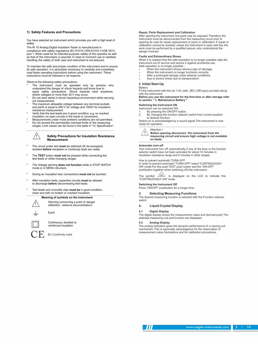
1) Safety Features and Precautions
You have selected an instrument which provides you with a high level ofsafety.
The RI 10 Analog-Digital Insulation Tester is manufactured in
compliance with safety regulations IEC 61010-1/EN 61010-1/VDE 0413part 1. When used for its intended purpose. safety of the operator, as wellas that of the instrument, is assured. In case of incorrect use or carelesshandling, the safety of both user and instrument is not assured.
To maintain the safe and proper condition of the instr ment and to ensureits safe operation, it is absolutely necessary to carefully and completelyread these operating instructions before using the instrument. Theseinstructions must be followed in all respects.
Observe the following safety precautions :
* The instrument must be operated only by persons whounderstand the danger of shock hazards and know how toapply safety precautions. Shock hazards exist anywhere,where voltages of more than 30 V may occur.
* Do not work alone in shock hazardous environment while carryingout measurement.
* The maximum allowable voltage between any terminal socketsand earth is equal to 600 V for voltage and 1000V for Insulationresistance measurement.
* Verify that the test leads are in good condition, e.g. no crackedinsulation, no open circuits in the leads or connectors.
* Measurements under moist ambient conditions are not permitted.* Do not exceed the permissible overload limits of the measuring
ranges. Limit values can be found in the table in “12. Specification”.
Safety Precautions for Insulation ResistanceMeasurement
* The circuit under test be switched off, de-energized,mustisolated Insulation or Continuity tests are made.before
* The button be pressed while connecting theTEST must nottest leads or while changing ranges.
* The Voltage warning while in STOP WATCHdoes not functionmode or in MENU structure.
* During an Insulation test, connections be touched.must not
* After insulation tests, capacitive circuits be allowedmustto discharge disconnecting test leads.before
* Test leads and crocodile clips in good condition,must beclean and with no broken or cracked insulation.
u
Earth
Continuous, doubled orreinforced insulation
Warning concerning a point of danger(Attention : observe documentation)
Meaning of symbols on the instrument
CE EU Confirmity mark
Repair, Parts Replacement and Calibration
After opening the instrument, live parts may be exposed.Therefore, theinstrument must be disconnected from the measuring circuit prior toopening its case for repair, replacement of parts or calibration. If repair orcalibration cannot be avoided, unless the instrument is open and live, thework must be performed by a qualified person, who understands thedanger involved.
Faults and Extraordinary Stress
When it is realized that the safe operation is no longer possible, take theinstrument out of service and secure it against accidental use.Safe operation is no longer possible -n When the instrument shows obvious sign of damage,n When the instrument no longer functions correctly,n After a prolonged storage under adverse conditions,n Due to severe stress due to transportation.
2 Initial Start-UpBatteryFit the instrument with the six 1.5V cells (IEC LR6 type) provided alongwith the instrument.Before you use the instrument for the first time or after storage referto section '' 3. Maintenance Battery ''
Switching the Instrument ON
Instrument can be switched ON :1. By pressing the ON/OFF button.2. By changing the function selector switch from current position
to desired function.Switch-on is acknowledged by a sound signal.The instrument is nowready for operation.
Attention !
Before opening disconnect the instrument from themeasuring circuit and ensure high voltage is not availableon leads.
Automatic turn-off
Your instrument turn off automatically, if any of the keys or the functionselector switch have not been activated for about 10 minutes ininsulation resistance range and 5 minutes in other ranges.
How to prevent automatic TURN-OFFIn order to prevent automatic “TURN-OFF” select “CONTINUOUSLYON” mode For this push TEST push button and the “ON-OFF”pushbutton together when switching ON the instrument.
The symbol is displayed on the LCD to indicate this“CONTINUOUSLY ON” mode.
Switching the Instrument Off
Press “ON/OFF” pushbutton for a longer time.
3. Selecting Measuring FunctionsThe desired measuring function is selected with the Function selectorswitch.
4. Liquid Crystal Display
4.1 Digital Display
The digital display shows the measurement value and decimal point.Theselected measuring unit and function are displayed.
4.2 Analog Display
The analog indication gives the dynamic performance of a moving coilmechanism.This is especially advantageous for the observation ofmeasurement value fluctuations and for calibration procedures.
ON

Insulation Resistance Measurement
NoteDuring Insulation resistance measurement the symbol
flashes as long as the high voltage is present at the terminals
ON
RI 10
R
50V
100V250V
500V1KV
V
M�
www.ziegler-instruments.com 4 | 10
5. Insulation Resistance Measurement (M )�
5.1. Preparation for measurement�Select the required "Test Voltage (50V/100V/250V/500V/1000V)"
by changing the "Function Selector Switch".�Connect the test probes firmly to the circuit under test.
Note !Insulation resistance can only be measured at voltage freeobject. Hence the circuit under test must be switched off,de-energized and isolated before carrying out any insulationresistance measurement.
When measuring high-ohmic insulation resistance do nottouch the measurement cables.
If an interference voltage > 25V is present within thesystem, insulation resistance measurement is disabled.The instrument defaults to the default voltmeter anddisplays the value of the interference voltage on the LCD.Also the instrument indicates this additionally by anacoustic signal.
HIGH-VOLTAGEDo not touch the conductive ends of the test probesafter insulation resistance measurement has beenactivated at the instrument.
A current with a value of 2 mA (limited by the instrument)may flow over your body, and although this is not lifeendangering, the electric shock is distinctly perceptible.If you are taking a measurement at a capacitive device under test, forexample a cable, it may be charged with as much as1000V, depending upon the selected nominal voltage.Touching thedevice under test after measurement may be life endangering in suchcases!
5.2 Insulation resistance measurementThe instrument provides flexibility for both manual andcontinuous (for a pre-selectable time) insulation - resistancemeasurement.
5.2.1 Manual Insulation resistance measurement :In manual Insulation resistance measurement, Press and hold "TEST"key until the display has stabilized. Insulation resistance measurement isended when the yellow TEST key is released. Instrument will continue toshow the last reading for few seconds even after releasing the "TESTkey".
Note !The instrument's batteries are depleted during insulationresistance measurement. Only press and hold the TEST keyas long as it is necessary to take the reading in the manualmeasurement mode. Continuous measurement as describedbelow should be performed, if absolutely necessary.
210

5.2.2 Continuous measurement for a pre-selectable time :
In normal course, the insulation test terminates when the test keyis released and the measured insulation resistance value remainson display for few seconds after the test key is released.With the Pre-selectable measurement time feature, theinsulation test continues for the pre-determined time.Pre-selectable time : 10 sec-5 minRefer to the “11. Menu structure” section for how to set the value for pre-selectable time. Once the time is set it is applicable to all the 5 ranges ofInsulation measurement.
n Select the required value of the time for which the test isto be carried out.
n Briefly Press the TEST key. The insulation resistancetest carries on for the time interval selected.
n The test terminates automatically after the selected timehas elapsed.
n The display then flashes the value of measurement atthe end until the Key is pressed.
5.3 Conclusion of measurement and discharging
After the measurement has been completed, any residual voltage isdisplayed which may be caused by capacitive circuits. Contact with thedevice under test must be maintained.The reduction in voltage can bedirectly observed at the LCD.
Do not disconnect the device under test until voltage has droppedbelow 25 volts !!
Note : Automatic discharge !The capacitive circuits are automatically discharged whenTEST button is released following an insulation resistance test.This auto discharge facility eliminates the need for the user todischarge the circuit under test manually.
Additional features available in Insulation measurement ranges.
1. Pre-selectable limit checks (Go/Nogo option)2. Storing the measured resistance value3. Minimum and Maximum value “MIN/MAX” storage
www.ziegler-instruments.com 5 | 10
6 Additional Features
6.1 Pre-selectable limit checks (Go/No-Go option)An acoustic signal can be generated when the measured value ofresistance falls below an adjustable noGo value.A separate noGo value can be set for each range of insulationresistance measurement as well as for Ohms, Continuity ranges.Refer to the “11. Menu structure” section for how to set the valuefor the noGo value.
6.2 Storing the measured resistance valuel To store the value of resistance press “STORE” key when the
resistance measurement is in progress. This will store theresistance measured at the instant the key is pressed.
l This way maximum 10 readings per range can be stored.th
l After 10 values are stored for the selected range the 11 valuewhen stored will over-write the first value i.e. at any given pointof time only ten readings per range can be stored.
l The readings are stored in a volatile memory.Therefore when theinstrument is switched off, the readings are lost.
Recalling the stored valuesThe stored values can be recalled and viewed in the menustructure.Refer to the “11.Menu Structure” section for how to view thestored value.
6.3 Minimum value and Maximum value “MIN/MAX” storagefacility (for all measuring ranges)
With the MIN/MAX function, you can hold the minimum and themaximum measured value which was applied to the input of theinstrument after activating MIN/MAX.The most important application isdetermination of minimum and the maximum value for long termmonitoring of measured quantities.The function MIN/MAX can be activated in all measuring ranges.MIN/MAX does not influence analog indication, you can still read theactual measured value.
Apply the measured quantity to instrument prior to activating MIN/MAXfunction.
The MIN/MAX function is switched off when.
1. Key is pressed for approximately for 1 Sec. OR
2. Then function selector switch is operated OR
3. When the instrument is turned OFF and ON again
FunctionMIN/MAX
Measured ValueMIN and MAX
Meter reaction
Display
Measured value DigitalMIN/MAX
Soundsignal
1. Activateand store
2. Storeand display
3. Returnto 1.
Reset
short
short
short
short
long
Stored
Stored continuedin backgroundnew MIN and MAXvalues are displayed
Same as 1.Stored values arenot cleared
Cleared
Actual measured value
Stored MIN value
Stored MAX value
Same as 1.
Cleared
MIN/MAXflash
MIN flash
MAX flash
Same as 1.
Cleared
1x
1x
1x
1x
2x

Continuity Test
-
0 0
RI 10
0
M�
50V
100V250V
500V1KV
V
+
-
RI 10
0L
M�
50V
100V250V
500V1KV
V
+
www.ziegler-instruments.com 6 | 10
7. Continuity Testing and Resistance Measurement
Attention !Be absolutely certain that the device under test isvoltage-free.
7.1 Continuity Testing* Verify that device under test is electrically dead.* Set the function selector switch to “ ” position.* If required null lead resistance by doing Zero adjustment below.* Connect the device under test as shown in diagram.* The measured resistance value will be displayed on the display.* The instrument generates a continuous sound signal if
the measured resistance value is less than the pre-setted“GoNoGO” value. Default value is 5�
Refer to the “11. Menu structure” section for how to set the valuefor the limit value.
7.2 Low Ohm Measurement ( )�* Verify that device under test is electrically dead.* Set the function selector switch to “ ” position.�
* If required null lead resistance by doing zero adjustment below.* Connect the device under test as shown in diagram* The measured resistance value will be displayed on the display.* The instrument generates a continuous sound signal if the
measured resistance value is less than the pre-setted“GoNoGO” value. Default value is 0�
Refer to the “11. Menu structure” section for how to set thevalue for the limit value.
7.3 Zero adjustmentWhen measuring very low resistance values, you can eliminateresistance of leads and contact resistance by zero adjustment.
* Connect the test leads to instrument and connect the free ends ofthe leads to one another.
* Wait for reading to stabilize.* Briefly press the “TEST” push button. The instrument
acknowledges zero adjustment by a sound signal andthe LCD shows “0.00” (+1digit) and the symbol “ZERO” (17) isdisplayed.The resistance measured at the instant the push buttonis pressed is used as reference value (0-9.99 ). It is automatically�
deducted from the values measured thereafter.* Zero adjustment can be cleared.
Ø By pressing the “TEST” button once again.Ø By switching the instrument off.Also zero adjustment is cleared when Auto shutOFF operates.
Additional features available in Ohm and Continuity ranges.
1. Pre-selectable limit checks (Go/Nogo option)2. Storing the measured resistance value.3. Minimum and Maximum value “MIN/MAX” storage.

8. Voltage Measurement (V AC/DC)
You can use this instrument for voltage measurement from 25V to 600VAC or DC.
* Keep the function selector switch to “V ” position andapply the input.
* The instrument automatically displays whether the inputis AC or DC along with the value of the external voltage.
* If the value of voltage is < 25V (AC or DC), the display“025V” flashes. If the value of the voltage is > 600V (ACor DC), a continuos acoustic signal is generated.
* When reverse DC is applied it displays “-dc”
Additional features available in Insulation measurement ranges.1. Minium and Maximum value “MIN/MAX” storage
Voltage Measurement
9. Default Live Circuit Warning
When more than 25V (AC or DC) is applied to the terminals theinstrument defaults to voltmeter on all switch positions. In addition thebeeper will sound on all switch position (except the V position).
When external voltage>25 V is present, Insulation Ohm and ContinuityTests are inhibited.
When external voltage <25 V is present, only the Insulation Tests areavailable !!
Note : The default live circuit warning does not operate(i) when in STOPWATCH mode.(ii) when in MENU structure.
+(-)/~
-(+)/~
RI 10
M�
50V
100V250V
500V1KV
V
www.ziegler-instruments.com 7 | 10
10 Stop Watch
This function allows you to measure elapsed time up to one hour.To use stop-watch
1. Set the function selector switch to Continuity " " position.
2. “TEST” 00:00Press key.This will show the stopwatch from
3. RESETPress key at any time to the stopwatch.
4. START STOPPress key at any time to or the stopwatch.
5.To quit stopwatch and go back to basic display, Press key.“TEST”
11 Menu StructureStructure of command menu for Insulation measurement :
Structure of command menu for Resistance & Continuity measurement
Menu structure Insu 10Confirmation of selectedmenu item via ENTER key
Select next menu itemin the flow direction
Go back to previouslevel of menu
= Time= Recall= Minutes= Seconds= Value for noGo= Strored value
mmss
nnnnxxxx
BasicDisplay
nnnn
mm:ss
xxxx
BasicDisplay
nnnn
xxxx
xxxx
Esc
229

11.1 Description of Menu Items :
11.1.1 Setting the GoNoGo values :(at all ranges except V )
Operating Order :
Basic noGo nnnnDisplaySetting : nnnn = noGo limit values in M (for Insulation ranges)�
nnnn = noGo limit values in (for Ohm and Continuity)�
1.Now scroll through different values using the key untilyou come across required value.
2.To save this value press key. After saving, this will takeyou to basic display.
3.To go back without saving press "ESC" key.This will take you tomain menu "noGo"
4.To go back to basic display from main menu "noGo" use "ESC" key.
11.1.2 Setting the Timer values(Only at Insulation Resistance measurement ranges)
Operating Order :Basic noGo ti mm:ssdisplay
Setting : mm= minutes, ss = seconds
1. Now scroll through different values using the key untilyou come across required value.
2. To save this value press key. after saving, this will takeyou to basic display.
3. To go back without saving press key.This will take you to"ESC"main menu "ti"
4. To go back to basic display from main menu "ti" use key."ESC"
11.1.3 To see the stored values(at all ranges except V )
Operating Order :Basic noGo ti reCL nnnndisplay
1. You can now see the first stored value.The scale pointer is usedto indicate the number (out of 10) of the displayed stored value.
2. Now you can view the successive stored value using thekey.The scale pointer also increments to indicate the number(out of 10) of the displayed stored value.
3. To go back press key.This will take you to"ESC"main menu "reCL"
4 To go back to basic display from main menu "reCL" use key."ESC"
Table for default values :
NoGo ti reCI
50V
100V
250V
500V
1000V
Ohm
Cont
V
1 M�
1 M�
5 M�
5 M�
500 M�
00 �
5 �
---
00:00 (Manual)
---
---
---
0.00
0.00
0.00
0.00
0.00
0.00
0.00
---
www.ziegler-instruments.com 8 | 10
12. Specifications
Meas. Range Resolu- Accuracy Overloadfunction tion (..% of rdg value and
+ .. digit) duration±
1) For insulation resistance range, 2) For low Ohms/continuity Ranges* Terminal voltage on open * Open circuit voltage
circuit (DC) 5V ± 1V d.c.- 0% to + 30% of rated voltage * Lead resistance
* Short circuit current < 2 mA compensation : 0 - 9.99 �* Test current on load 1 mA at
minimum pass values ofinsulation as specifiedin VDE 0413 Part 1.
Reference Conditions :0
Ambient Temp. +23C ± 2 KRelative Humidity 45%...55%Battery Voltage 8V ± 0.1VVoltage Measurement AC (Sine), 50/60 Hz
DisplayLCD display field (65 mm x 30 mm) with analog indication and Digitaldisplay and with display of unit of measured quantity and functions
AnalogDisplay LCD scale with bar graph pointerScale Length 47 mm
Scaling 0...30 with 30 graduationsOver range Indication By triangle (13)
DigitalDisplay/Char. Height 7 segment digits/12mmNumber of Digits 3 digit for M and� �
4 digit for Stop watchOver range Indication OL
InsulationResistance
1)M�U = 50 V,N
100 V
0.01 M to�0.99 M�
� �1.0 M to9.9 M�
� �10 M to99 M�
10 K�( )0.01 M�
100 K to�( )0.1M�
1 M�
± 3% ± 2
± 5% ± 2
± 30%
1200V rms,10 sec
InsulationResistance
1)M�U = 250 V,N
500 V,1000 V
0.01 M to�9.99 M�
� �10.0 M to99.9 M�
� �100 M to999 M�
10 K�( )0.01 M�
100 K to�( )0.1M�
1 M�
± 3% ± 2
± 5% ± 2
± 30%
1200V rms,10 sec
2)Low Ohms
�
0 9.99� �
� �� �10 99.9
0.01 at�210 mA
���� at21 mA
± 3% ± 2
± 5% ± 2
1200V rms,10 sec
2)Continuity 0 9.99� �
� �� �10 99.9
0.01 at�210 mA
���� at21 mA
± 3% ± 2
± 5% ± 2
1200V rms,10 sec
V AC/DC 1 V ± 2% ± 3 1200V rms,10 sec
� �25V 450V
� �450V 600V 1 V ± 3%

0.01M� 0.1M� 0.5M� 1.0M� 10M� 100M�
Insulation Resistance
Ou
tpu
t V
olt
ag
e (
V)
1300
1200
1100
1000
900
800
700
600
500
400300
200
100
1000 V Range
500 V Range
250 V Range
0.1M�0.05M� 1M� 10M�
Insulation Resistance
Ou
tpu
t V
olt
ag
e (
V)
130
120
110
100
90
80
70
60
50
40
30
20
10
100 V Range
50 V Range
10M�
Required min. Value of Insulation Resistance(Limiting Value)
Min
imu
m D
isp
lay V
alu
e
5M�
2M�
1M�
0.5M�
0.2M�
0.2M� 0.5M� 1M� 2M� 5M�
www.ziegler-instruments.com 9 | 10
Power Supply
Battery 6 x 1.5V cells IEC LR6(Nickel cadmium rechargeable cellsmay be used)
Service Life Typically 2500 x 5 second operations withalkaline manganese cells
Battery Test
Battery symbol “ ” appears on the LCD in either of below conditions :1. Battery voltage is <5.4V. Battery replacement is necessary.2. For a specific range depending on application
In either of the above condition, when the battery symbol is displayed, nomeasurement can be done, and the battery symbol flashes.
Note : Battery cells should not be left in the instrument which may remainunused for extended period of time.
Auto turn OFFInstrument turns off automatically, if any of the keys or the functionselector switch have not been activated for about 10 minutes ininsulation resistance range and 5 minutes in other ranges.
Cable Set2
Cu cross-sectional area 1 mmEnd metallic parts should pass terminal 4 D 11Technical data as per IEC 61010 / EN 61010-2-031 CATIII/1000V,Air/creepage 16 mm.�
High Voltage test 7.4KV AC for 1 min.Breaking force of the cable 36N, 1 min.�
Fuse 500 mA(F)/440V H.B.C. 10 kA min (32mmx6mm)
Electrical SafetyProtection Class II per IEC 61010-1/EN61010-1/VDE0411-1Over voltageCategory II IIINominal Voltage 600V 300VContamination degree 2 2Test Voltage 3.7KV~per IEC 61010-1/EN61010-1
EMC
IEC/EN 61326 Electromagnetic Compatibility (EMC)
Environmental Conditions0
Nominal Temp. Range 0.....35C0 0
Operating Temp. -20C... + 40C (full range)0 0
-20C... + 60C (up to 100 M )�0 0
Storage Temp -25C...+65C0
Relative Humidity 90% RH at 40C max.0
Temperature Coefficient <0.1%perC
Mechanical Design
Protection Instrument :IP 50For terminal socket : IP 20 according toDIN VDE 0470 Part 1 / EN60529
Dimensions W x H x D84mm x 195 mm x 35 mm
Weight 500 g including battery
13 Maintenance
Attention !Disconnect the instrument from the measuring circuit before openingthe instrument to replace the battery or the fuse !
13.1 Battery
Before initial Start-up, or after long storage of your instrument, makesure that no leakage has occurred at the instrument battery. Repeat thisinspection at regular intervals.
Battery symbol “ ” appears on the LCD in either of below conditions:1. Battery voltage is <5.4 V. Battery replacement is necessary.2. For a specific range depending on application
In either of above condition when the battery symbol is displayed, nomeasurement can be done, and the battery symbol flashes.
Replacing the Batteries
* Lay the instrument on to its face, loosen the two screws at the rarepanel and lift out the housing base, starting at the bottom (a).Thehousing base and the housing top are held together with snap hooksat the top of the front panel.
* Remove all the cells from the battery holder and replace them withnew ones.
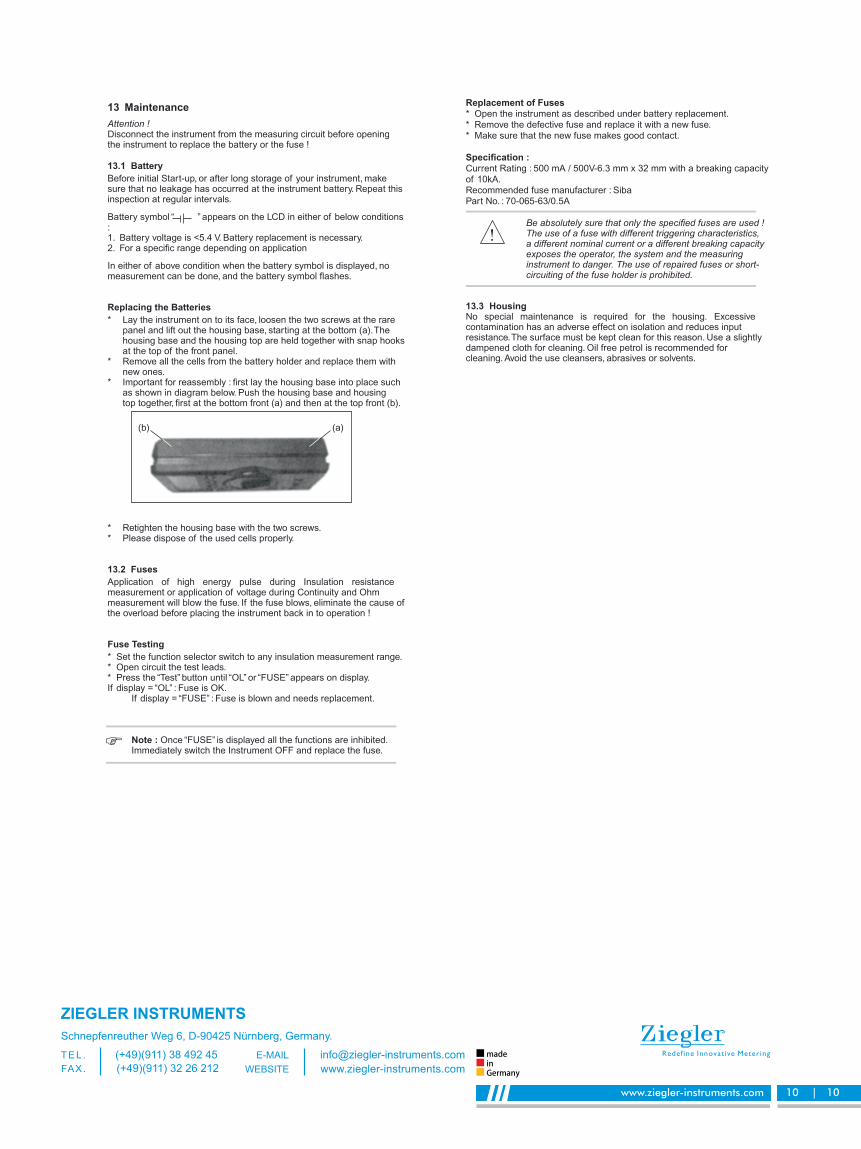
* Important for reassembly : first lay the housing base into place suchas shown in diagram below. Push the housing base and housingtop together, first at the bottom front (a) and then at the top front (b).
* Retighten the housing base with the two screws.* Please dispose of the used cells properly.
13.2 Fuses
Application of high energy pulse during Insulation resistancemeasurement or application of voltage during Continuity and Ohmmeasurement will blow the fuse. If the fuse blows, eliminate the cause ofthe overload before placing the instrument back in to operation !
Fuse Testing
* Set the function selector switch to any insulation measurement range.* Open circuit the test leads.* Press the “Test” button until “OL” or “FUSE” appears on display.If display = “OL” : Fuse is OK.
If display = “FUSE” : Fuse is blown and needs replacement.
Note : Once “FUSE” is displayed all the functions are inhibited.Immediately switch the Instrument OFF and replace the fuse.
(b) (a)
www.ziegler-instruments.com 10 | 10
Replacement of Fuses* Open the instrument as described under battery replacement.
* Remove the defective fuse and replace it with a new fuse.
* Make sure that the new fuse makes good contact.
Specification :Current Rating : 500 mA / 500V-6.3 mm x 32 mm with a breaking capacity
of 10kA.
Recommended fuse manufacturer : Siba
Part No. : 70-065-63/0.5A
Be absolutely sure that only the specified fuses are used !The use of a fuse with different triggering characteristics,a different nominal current or a different breaking capacityexposes the operator, the system and the measuringinstrument to danger. The use of repaired fuses or short-circuiting of the fuse holder is prohibited.
13.3 HousingNo special maintenance is required for the housing. Excessivecontamination has an adverse effect on isolation and reduces inputresistance.The surface must be kept clean for this reason. Use a slightlydampened cloth for cleaning. Oil free petrol is recommended forcleaning. Avoid the use cleansers, abrasives or solvents.
ZIEGLER INSTRUMENTS
Schnepfenreuther Weg 6, D-90425 Nürnberg, Germany.
(+49)(911) 38 492 45T E L .
(+49)(911) 32 26 212FAX.
www.ziegler-instruments.com
WEBSITEinGermany
made